EP2934251B1 - Vorrichtung zur erzeugung von milchschaum - Google Patents
Vorrichtung zur erzeugung von milchschaum Download PDFInfo
- Publication number
- EP2934251B1 EP2934251B1 EP13819026.9A EP13819026A EP2934251B1 EP 2934251 B1 EP2934251 B1 EP 2934251B1 EP 13819026 A EP13819026 A EP 13819026A EP 2934251 B1 EP2934251 B1 EP 2934251B1
- Authority
- EP
- European Patent Office
- Prior art keywords
- milk
- outer cylinder
- air
- rotatable element
- motor
- Prior art date
- Legal status (The legal status is an assumption and is not a legal conclusion. Google has not performed a legal analysis and makes no representation as to the accuracy of the status listed.)
- Active
Links
Images


Classifications
-
- A—HUMAN NECESSITIES
- A47—FURNITURE; DOMESTIC ARTICLES OR APPLIANCES; COFFEE MILLS; SPICE MILLS; SUCTION CLEANERS IN GENERAL
- A47J—KITCHEN EQUIPMENT; COFFEE MILLS; SPICE MILLS; APPARATUS FOR MAKING BEVERAGES
- A47J31/00—Apparatus for making beverages
- A47J31/44—Parts or details or accessories of beverage-making apparatus
- A47J31/4496—Means to produce beverage with a layer on top, e.g. of cream, foam or froth
-
- A—HUMAN NECESSITIES
- A47—FURNITURE; DOMESTIC ARTICLES OR APPLIANCES; COFFEE MILLS; SPICE MILLS; SUCTION CLEANERS IN GENERAL
- A47J—KITCHEN EQUIPMENT; COFFEE MILLS; SPICE MILLS; APPARATUS FOR MAKING BEVERAGES
- A47J31/00—Apparatus for making beverages
- A47J31/44—Parts or details or accessories of beverage-making apparatus
- A47J31/4485—Nozzles dispensing heated and foamed milk, i.e. milk is sucked from a milk container, heated and foamed inside the device, and subsequently dispensed from the nozzle
-
- A—HUMAN NECESSITIES
- A47—FURNITURE; DOMESTIC ARTICLES OR APPLIANCES; COFFEE MILLS; SPICE MILLS; SUCTION CLEANERS IN GENERAL
- A47J—KITCHEN EQUIPMENT; COFFEE MILLS; SPICE MILLS; APPARATUS FOR MAKING BEVERAGES
- A47J31/00—Apparatus for making beverages
- A47J31/44—Parts or details or accessories of beverage-making apparatus
- A47J31/46—Dispensing spouts, pumps, drain valves or like liquid transporting devices
-
- A—HUMAN NECESSITIES
- A23—FOODS OR FOODSTUFFS; TREATMENT THEREOF, NOT COVERED BY OTHER CLASSES
- A23C—DAIRY PRODUCTS, e.g. MILK, BUTTER OR CHEESE; MILK OR CHEESE SUBSTITUTES; PREPARATION THEREOF
- A23C7/00—Other dairy technology
-
- B—PERFORMING OPERATIONS; TRANSPORTING
- B01—PHYSICAL OR CHEMICAL PROCESSES OR APPARATUS IN GENERAL
- B01F—MIXING, e.g. DISSOLVING, EMULSIFYING OR DISPERSING
- B01F23/00—Mixing according to the phases to be mixed, e.g. dispersing or emulsifying
- B01F23/20—Mixing gases with liquids
- B01F23/23—Mixing gases with liquids by introducing gases into liquid media, e.g. for producing aerated liquids
- B01F23/235—Mixing gases with liquids by introducing gases into liquid media, e.g. for producing aerated liquids for making foam
- B01F23/2351—Mixing gases with liquids by introducing gases into liquid media, e.g. for producing aerated liquids for making foam using driven stirrers
-
- B—PERFORMING OPERATIONS; TRANSPORTING
- B01—PHYSICAL OR CHEMICAL PROCESSES OR APPARATUS IN GENERAL
- B01F—MIXING, e.g. DISSOLVING, EMULSIFYING OR DISPERSING
- B01F2101/00—Mixing characterised by the nature of the mixed materials or by the application field
- B01F2101/06—Mixing of food ingredients
- B01F2101/07—Mixing ingredients into milk or cream, e.g. aerating
Definitions
- the present invention is directed to a device for foaming a fluid, preferably for producing milk foam.
- the device is designed in a way that it can be positioned to produce foam in-line of a fluid flow path.
- the device of the present invention uses high shear energy experienced by the fluid in the device as foaming energy for producing the foam.
- a device for producing milk foam that has a reservoir, into which milk can be filled.
- a rotating part in the reservoir for example a whisk provided at the bottom surface of the reservoir, causes the foaming of the milk.
- Such a device for producing milk foam can produce only a predetermined amount of milk foam at the same time, i.e. in one batch process. Afterwards, the device needs to be emptied, preferably cleaned, and refilled with milk before the next batch process can be started. Furthermore, such a device cannot be implemented in-line of a fluid flow path, and thus e.g. in a device for producing or providing milk or other beverages.
- the state of the art includes devices that inject hot steam into milk that is filled into a reservoir, in order to cause foaming.
- such devices cannot be used in-line of a fluid flow path of e.g. a beverage producing device.
- the state of the art further includes a device for producing milk foam as disclosed in DE 197 19 784 C1 comprising a rotatable element arranged within a cylinder, a fluid inlet delivering fluid to the cylinder, said device for producing milk foam wherein a milk supply circuit supplies milk to the fluid inlet and an air supply circuit which supplies air to the same fluid inlet, both milk and air supply circuits being independent from each other.
- the factors that influence the foaming of the milk are, for example, the geometry of the rotating part, like the whisk, or the temperature and/or pressure of the steam that is injected into the milk. These factors are difficult to understand, and are not easy to control accurately without building more complicated devices. Therefore, the milk foam of many simple state of the art foaming devices is often produced unreliably, i.e. the properties of the foam like volume, foaming level, foam stability etc. differ from one batch process to another.
- the present invention has an object to provide a device for foaming a fluid, preferably for producing milk foam, which can be implemented in-line of a fluid flow path. Further, the present invention desires to provide a device, with which the foam can be produced more reliably and in a consistent manner. Therefore, the factors influencing the foaming effect should be better understandable and easier to control accurately. Another object of the present invention is to provide a simple and robust device that has a long life time.
- the invention is not limited to milk as a fluid, but can also be applied to other fluids, e.g. chocolate or coffee. Consequently, other foams than milk foam can be achieved by the present invention as well.
- both milk and air have to be provided in some manner as shown in fig. 1 .
- the milk and/or the air can be heated.
- some kind of foaming energy has to be provided to the milk and the air, in order to produce the milk foam.
- the present invention bases on the ideas that the supply of air and milk are controlled separately, and that the foaming energy is provided as a high shear energy.
- the high shear energy is achieved by designing the device such that a milk-air mixture is passed at least partly by Couette flow through the device.
- Couette flow refers to a laminar flow of a viscous fluid in a space between two parallel plates.
- the basic principle of Couette flow is shown in fig. 2 .
- a movable two-dimensional boundary plate moves with a certain velocity u in respect to a stationary two-dimensional boundary plate.
- the movement of the movable boundary plate causes the fluid to move.
- Two boundary conditions define the movement of the fluid.
- the fluid does not move at all, due to friction forces at the stationary boundary plate. Therefore, the velocity u is zero.
- friction causes the fluid to move with the velocity u of the movable boundary plate.
- the velocity u of the fluid increases linearly in a direction y measured from the stationary boundary plate.
- a shear stress ⁇ is caused in the fluid, which depends on the distance between the two boundary plates, the viscosity of the fluid, and the absolute velocity of the moving boundary plate.
- the shear stress in the fluid results in a shear energy, which can be used as foaming energy. Details will be described by the present invention.
- the present invention realizes the above-mentioned principle with a device according to the attached independent claims.
- the independent claims solve the above-mentioned problems of the state of the art. Further advantages of the present invention are developed in the attached dependent claims.
- a key feature of the present invention is that milk and air are provided via two separate supply circuits, i.e. a milk supply circuit and an air supply circuit.
- the amount of air and milk supplied can thus be separately controlled, which allows it to control the foam properties particularly well.
- the milk supply circuit comprises a feedback control loop with a flow meter and a regulator.
- the air supply circuit equally comprises a feedback control loop with a flow meter and a regulator, for example a PID regulator.
- a different ratio of milk and air used in the foaming process can be chosen, so that a wide range of different foam recipes can be produced by the device.
- the ratio of milk to air volume can range from 3: 1 to 1:7.
- Target values for different milk and air flow rates corresponding to different recipes can be stored in a control unit of the device and used to regulate the flow accordingly depending on the desired recipe.
- a device for producing milk foam comprises an outer cylinder, an inner cylinder arranged concentrically within the outer cylinder, a fluid inlet and a fluid outlet, wherein the outer cylinder and the inner cylinder are rotatable with respect to each other, wherein a gap is formed between the outer cylinder and the inner cylinder, and wherein the gap connects the fluid inlet with the fluid outlet.
- the outer cylinder has an inner wall and the inner cylinder has an outer wall, the inner wall and the outer wall realizing two parallel boundary plates, the relative movement of the inner cylinder against the outer cylinder causing a Couette flow of a fluid in a space between the two parallel plates.
- the device can comprise a rotatable whisk or any other rotating element instead of the inner cylinder.
- the two boundary plates shown in fig.2 are respectively realized by the outer wall of the inner cylinder and the inner wall of the outer cylinder.
- the movement of the movable boundary plate against the stationary boundary plate in fig. 2 is caused by the relative movement of the inner cylinder against the outer cylinder.
- the cylinders have a common rotation axis.
- the distance between the boundary plates in fig. 2 is defined by the width of the gap, through which a fluid, preferably milk and air, flows from the fluid inlet to the fluid outlet. That means milk and air are preferably provided to the fluid inlet of the device. Consequently, following the principle described in respect to fig. 2 , the milk-air mixture experiences a high shear stress in the gap.
- the high shear stress leads to an emulsion of the air and the milk. As soon as the emulsified milk-air mixture leaves the gap it expands. Due to the expansion a foaming effect is achieved, since the size of air bubbles within the milk increases abruptly. Therefore, generally speaking a high shear energy contained in the milk-air mixture is used to provide the foaming energy, which is necessary to produce the milk foam.
- the device is designed such that it can be positioned in-line with a flow path of the milk, since the milk can flow into the fluid inlet, through the gap, and out of the fluid outlet.
- the device is therefore suited to continuously receive milk from a reservoir and convert it into milk foam.
- Factors that influence the milk foam properties are e.g. the width of the gap, the tangential speed of the cylinders with respect to each other, the cylinder surface and the time during which the milk is exposed to the shear stress, i.e. the time spent in the device. Such parameters are easy to understand and can be controlled precisely. Moreover, the device can be designed rather simple, but can still produce very reliable results.
- a width of the gap for example in the radius direction of the inner cylinder and the outer cylinder is in a range of 0.2 to 1.0 mm, even more preferably in a range of 0.3 to 0.6 mm.
- the shear stress experienced by the milk-air mixture in the device depends largely on the width of the gap that is formed between the two cylinder walls.
- the gap diameter is chosen such that a shear stress is achieved, which yields an optimal foaming effect of the milk. That means, for instance, that the foaming effect leads to milk foam having optimal properties.
- the present invention understands e.g. a desired volume, good foam stability and/or a sufficient foaming level. Stability is defined by the amount of time the milk foam is stable, i.e. substantially keeps its volume.
- the foaming level is defined by a ratio of the volume of the milk fed into the fluid inlet to the volume of the milk foam dispensed out of the fluid outlet.
- the fluid outlet has a diameter that is larger than the width of the gap, preferably in a range of 2 to 10 mm.
- the broadening of the fluid outlet compared to the width of the gap leads to the expansion of the milk-air emulsion produced by the high shear stress resulting from the relative rotation of the two cylinders.
- the expansion increases the size of air bubbles within the milk-air mixture, and thus causes a foaming effect.
- the preferred diameter of the fluid outlet causes an expansion that achieves milk foam with optimal properties.
- the inner cylinder can comprise a first part having a larger diameter and a second part having a smaller diameter, the gap being formed between the first part of the inner cylinder and the outer cylinder, and a chamber being formed between the second part of the inner cylinder and the outer cylinder.
- the offset between the two cylinders creates a first zone (in this case the gap) between the two cylinders, where the milk-air mixture experiences higher shear stress, and a second zone (in this case the chamber) between the two cylinders, where the milk-air mixture experiences lower shear stress.
- the high shear zone is used for emulsification of the milk-air mixture
- the low shear zone is used for expansion of the emulsification.
- the chamber has a width in the radius direction of the inner cylinder and the outer cylinder in a range of 2 to 10 mm.
- the optimal foam properties can be achieved within the device.
- the device further comprises a motor for rotating the rotating element with respect to the outer cylinder.
- the motor is adapted to rotate the inner cylinder with a rotation speed in a range of 4000 to 8000 rpm with respect to the outer cylinder.
- the shear stress between the rotating element and surrounding walls depends on the movement velocity, i.e. the relative rotation speed.
- the preferred values for the rotation speed have been found to yield the best foaming effect. That means the generated milk foam has the optimal properties.
- the motor comprises a shaft provided with a head part that comprises at least one first magnet
- the rotating element comprises at least one second magnet
- the at least one first magnet and the at least one second magnet are adapted to contactlessly transfer a rotation of the motor shaft onto the rotating element, i.e. for example an inner cylinder or a whisk.
- the shaft does not need to be mechanically connected to or inserted into the inner cylinder. Therefore, less friction will occur in the device, since no friction between the shaft and a guiding to or into the rotating element exists for rotating of the device. Less friction results in less energy consumption and a longer life time of the device.
- the device further comprises a water-impermeable separation element arranged between the motor and the rotating element.
- the separation element is made of metal or plastic.
- the separation element can be part of a housing of the device.
- a diameter of the outer cylinder or housing is in a range of 25 to 35 mm, preferably about 30 mm.
- the total volume of the gap defined between the two cylinders which depends not only on the width of the gap but also on the absolute diameters of the two cylinders, yields the desired amount of milk foam per time, when the device is operated.
- the volume of the gap formed above, below and around the whisk is crucial.
- the device further comprises a heater for heating fluid flowing from the fluid inlet to the fluid outlet.
- Heating of the milk and/or air provided via the fluid inlet into the gap can enhance the foaming effect due to additional available energy and/or protein denaturation. Further, hot milk foam is typically desired for preparing beverages like cappuccino or the like.
- the heater is preferably integrated within the housing, i.e. the outer cylinder.
- the invention also relates to a method for producing milk foam in a device as described above.
- the method comprises supplying milk to the fluid inlet via the milk supply circuit and supplying air to the fluid inlet via an air supply circuit that is independent from the milk supply circuit.
- Another aspect of the invention relates to a use of milk as milk to be frothed by a device as described above.
- milk and air supply circuits are part of the device according to the invention, they are not shown in Figures 3 to 7 for reasons of simplicity.
- FIG. 3 shows schematically a device 1 for producing milk foam according to a first embodiment of the present invention.
- the device 1 comprises an outer cylinder 2, which is at least partly hollow, wherein the hollow defines an inner diameter o of the outer cylinder 2.
- the inner cylinder 3 has an outer diameter i.
- the outer cylinder 2 and the inner cylinder 3 are rotatable against each other around a common rotation axis.
- the inner cylinder 3 is rotatable around the rotation axis, which is indicated in Fig. 3 by the broken line, i.e. the inner cylinder 3 is a rotator.
- the outer cylinder 2 is preferably fixed, i.e. the outer cylinder 2 is preferably a stator.
- the outer cylinder can e.g. be held fixed in a beverage producing device, which includes the device for producing milk foam of the present invention.
- the outer cylinder 2 can be a housing of the device 1 of the present invention, which can be held fixed by its own weight or the weight of the device 1 when e.g. standing on a surface.
- other solutions are possible, for example, that the outer cylinder 2 is rotated against a fixed inner cylinder 3 or that both cylinders 2 and 3 are rotated against each other.
- the gap 6 connects a fluid inlet 4 of the device 1 with a fluid outlet 5 of the device 1 in a way that a fluid, e.g. milk provided together with air, can pass through the device 1. That means in use of the device 1, preferably milk and air are entered into the fluid inlet 4, the mixture then flows through the gap 6 along the extension direction of the two cylinders 2 and 3 (i.e. the height of the cylinders), and finally exits the device 1 through the fluid outlet 5.
- a fluid e.g. milk provided together with air
- the width w of the gap 6, as measured in the direction of the radius of the inner cylinder 3 and the outer cylinder 2, respectively, is in a range of 0.1 to 1 mm, more preferably 0.2 to 0.6 mm, most preferably 0.3 to 0.5 mm. With such a gap the best foam properties for milk foam are achieved.
- the inner cylinder 3 can be solid or hollow.
- the inner cylinder 3 can include a heater 15, which is adapted to heat the milk and the air flowing through the gap 6.
- the heater can be arranged in the outer cylinder and thus heat the milk and the air flowing through the gap 6 from the outside.
- the heater 15 can be provided with electricity or it can include parts that move due to the rotation of the rotating cylinder, and are designed to convert the movement into heat.
- Fig. 4 shows the device 1 of Fig. 3 in a cross-sectional view.
- the inner cylinder 3 is located within the outer cylinder 2, and the gap 6 is formed between the cylinders 2 and 3, through which the milk-air mixture can flow and exit at the fluid outlet 5.
- the fluid outlet 5 preferably has an inner diameter d that is substantially larger than the width w of the gap 6.
- the diameter d is in a range of 1 to 20 mm, more preferably 2 to 10 mm, most preferably 5 to 10 mm.
- a ratio of the width of the gap 6 to the diameter d of the fluid outlet is preferably between 1:1 and 1:200, more preferably between 1:3 and 1:50, most preferably between 1:5 and 1:30. Due to the expansion of the milk-air mixture flowing out from the gap 6 into the fluid outlet 5, air bubbles within the milk increase in size, whereby a foaming of the milk is caused.
- the device 1 can provide milk from at its fluid outlet 5.
- Fig. 4 also shows that the device 1 comprises a motor 8, which is adapted to cause the rotation of the inner cylinder 3 with respect to the outer cylinder 2.
- the motor 8 is preferably provided separately to the two cylinders 2 und 3 e.g. in a separate chamber of the device 1 or at least with a separation 13, e.g. a plate, between the motor 8 and the cylinders 2 and 3.
- the separation 13 is preferably water impermeable, so that milk cannot enter the part of the device 1, in which the motor 8 is located.
- the motor 8 has preferably a shaft 9, which is rotated.
- the shaft 9 is preferably provided with a head part 10, which is wider than the shaft 9 and includes at least one first magnet 11.
- the separation 13 between the motor 8 and the inner cylinder 3 preferably comprises a protruding portion 13a, in which a recess 13b for receiving the head part 10 of the motor 8 is formed.
- the protruding portion 13a of the separation 13 is preferably received by a recess on the top surface of the inner cylinder 3.
- the inner cylinder 3 is preferably provided with at least one second magnet 12 arranged near its top surface, which is configured and positioned such that it interacts magnetically with the at least one first magnet 11 arranged in the head part 10 of the motor 8.
- the at least one first magnet 11 is also rotated and transfers its rotation through the magnetic coupling onto the at least one second magnet 12 of the inner cylinder 3.
- the rotation of the inner cylinder 3 with respect to the outer cylinder 2 is caused.
- the relative rotation speed of the two cylinders 2, 3 against each other is in a range of 1000 to 15000 rpm, more preferably 2000 and 10000 rpm, most preferably 4000 and 8000 rpm.
- the preferred rotation speed the best emulsification of the air-milk mixture in the gap 6 is achieved, and the best foaming properties of the milk foam are realized after expansion.
- the parts of the motor 8 are not contaminated with milk, and thus need not necessarily be cleaned very often.
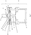
- Figure 5 shows the device 1 of Figures 3 and 4 in a perspective view.
- the device 1 comprises two parts, an upper part 1a that includes the motor 8 and a lower part 1b that includes the two cylinders 2 and 3.
- the two parts 1a and 1b of the device 1 are preferably coupled together by two flanges 14a and 14b, and are fixed with screws 15 as shown in figure 5 .
- An upper flange 14a can be designed to hold the motor 8 of the device 1, and a lower flange 14b can be designed to hold the cylinders 2 and 3 of the device 1.
- the upper flange 14a can also be produced integrally with a housing of the motor 8, and the lower flange 14b can be produced integrally with the outer cylinder 2.
- At least the lower flange 14b acts as the separation 13 of motor 8 and cylinders, as can be gathered from fig. 4 .
- the fluid inlet 4 is preferably arranged on an outer side surface of the outer cylinder 2, and can be produced integrally with the outer cylinder 2.
- Both the fluid inlet 4 and the fluid outlet 5 are preferably designed to attach two fluid lines coming from a milk supply circuit and an air supply circuit, such as tubes.
- the device 1 can then e.g. be integrated into a beverage producing device having e.g. pumps to provide milk and air to the fluid inlet 4.
- the device 1 itself can be provided with a mechanism so that a relative rotation of the cylinders 2 and 3 causes milk and air to be sucked into the fluid inlet 4, e.g. via a tube leading into an external milk reservoir.
- the milk foam can be provided directly, or can be provided via a tube to a dispenser.
- the device 1 of the present invention can thus provide milk foam in-line of a flow path of the milk, and can e.g. be part of a beverage producing device, e.g. a coffee machine.
- Figure 6 shows a cross section of an alternative embodiment of the device 1 of the present invention.
- the inner cylinder 3 comprises a first part 3a and a second part 3b.
- the first part 3a has diameter i that is larger than a diameter a of the second part 3b.
- a diameter i of the first part 3a is preferably chosen such that a gap 6 of a width w in a range of 0.1 to 1 mm, more preferably 0.2 to 0.6 mm, most preferably 0.3 to 0.5 mm is formed between a first part 3a and the outer cylinder 2.
- the diameter s of the second part 3b of the inner cylinder 3 is preferably designed such that a chamber 7 is formed between the second part 3b and the outer cylinder 2, wherein the chamber 7 has preferably a width measured in the radius direction of the inner cylinder 3 that is larger than the width w of the gap 6, preferably in a range of 1 to 20 mm, more preferably 2 to 10 mm.
- the diameter o of the outer cylinder 2 is preferably 20 to 40 mm, more preferably 30 mm as in the first embodiment of the present invention. Therefore, the diameter s of the second part 3b is most preferably in a range of 20 to 28 mm, and the diameter i of the first part 3a is most preferably in a range of 27.5 to 27.7 mm as in the first embodiment.
- Milk and air provided to the fluid inlet 4 for flowing through the gap 6 are emulsified due to the high shear forces experienced in the narrow gap 6 between the inner cylinder 3 and the outer cylinder 2, when the inner cylinder 3 is rotated with respect to the outer cylinder 2.
- the emulsified milk-air mixture flows out of the gap 6 into the chamber 7, it is expanded and consequently foamed. Due to the expansion, the foam is pressed out of the fluid outlet 5. If the fluid outlet 5 is even larger in diameter than the chamber 7, the milk is foamed even more.
- Figure 7 shows a cross-sectional view of yet another embodiment of a device 1' according to the present invention.
- the device 1' comprises an outer cylinder 2' forming a housing, which is at least partly hollow.
- a hollow compartment is formed, and a rotatable whisk 3' is arranged therein concentrically with the outer cylinder 2'.
- the whisk 3' has a disc-like shape with an outer diameter which is smaller than the inner diameter of the outer cylinder 2', so that a gap 6' is formed above, below and around the whisk 3'.
- the gap 6' connects a fluid inlet 4' of the device 1' with a fluid outlet 5' of the device 1' in a way that a fluid, e.g. milk provided together with air, can pass through the device 1'.
- the fluid inlet 4 is connected to an air and a milk supply circuit, both not shown in Fig. 7 .
- a fluid divider 40 sits insider the inlet 4' so that the milk and air entering the device 1' are evenly distributed around the whisk 3'.
- the inner whisk 3' Since the inner whisk 3' is rotated with respect to the outer cylinder 2' with only a narrow gap 6' around the whisk 3', while the milk-air mixture flows through the gap 6', the mixture experiences a high shear stress according to the principles of the Couette flow explained above.
- the high shear stress causes an emulsion of the milk and the air.
- the emulsion expands in the fluid outlet 5'.
- the fluid outlet 5' is arranged radially outwards of the whisk 3' and has an inner diameter which is bigger than the width of the gap 6', so that the air bubbles in the milk foam can expand therein.
- the width w of the gap 6' is in a range of 0.1 to 1 mm, more preferably 0.2 to 0.6 mm, most preferably 0.3 to 0.5 mm. With such a gap the best foam properties for milk foam are achieved.
- the device can include a heater which is not shown in Figure 7 .
- the device 1' comprises a motor 8', which is adapted to cause the rotation of the whick 3' with respect to the outer cylinder 2'.
- the whisk 3' turns around a guiding ball 42 which forms its axis of rotation.
- the motor 8' is provided in a separate chamber of the device 1' with a separation 13', e.g. a plate, between the motor 8' and the compartment containing the whisk 3' and the gap 6' through which the milk and air flow.
- the separation 13' is preferably water impermeable, so that milk cannot enter the part of the device 1', in which the motor 8' is located.
- the motor 8' has a shaft 9', which is rotated.
- the shaft 9' is 'provided with a head part 10', which is wider than the shaft 9' and includes at least one first magnet 11'.
- the whisk 3' is equally provided with at least one second magnet 12' arranged near its lower surface, which is configured and positioned such that it interacts magnetically with the at least one first magnet 11' arranged in the head part 10' of the motor 8'.
- the at least one first magnet 11' is also rotated and transfers its rotation through the magnetic coupling onto the at least one second magnet 12' of the whisk 3', thereby causing a rotation of the whisk 3'.
- all embodiments of the present invention are designed such that a shear stress value for the milk in the gap 6 that is in a range from 20 to 80 Pa, more preferably, 30 to 60 Pa, most preferably of 40 to 50 Pa is achieved, when assuming Newton's law of viscosity.
- the results in terms of milk foam quality depend not only on the instantaneous shear stress, but on the time during which this shear stress is applied. A typical value is 0.2s at a shear stress of 40 to 50 Pa, but good reulsts are also obtained with longer times.
- FIG 8 schematically shows the device 1 or 1' according to any of the previously described embodiments with a milk supply circuit 88 and air supply circuit 89. These circuits 88, 89 are part of the overall device, but have been omitted in Figures 3 to 7 for the sake of simplicity.
- the milk supply circuit 88 comprises a milk tank 80 from which milk is pumped towards the inlet 4, 4' of the device 1 using an air pump 83.
- the air pump 83 simply pushes air into the milk tank 80, so that milk is pushed out of the tank 80 towards the inlet 4 of the device 1.
- a flowmeter 81 and a regulator 82 form a feedback loop.
- the milk flow rate is compared to a target value, and the pump adjusted, typically by adjusting a voltage applied to the pump, if the measured value does not correspond to the target value.
- the air supply is controlled via another regulator 85 using values provided by a flowmeter 84 and regulating another air pump 86.
- a different ratio of milk and air can be chosen, so that a wider range of different foam recipes can be produced by the device.
- the ratio of milk to air volume can range from 3: 1 to 1:7.
- Target values for different milk and air flow rates corresponding to different recipes can be stored in a control unit of the device and used to regulate the flow accordingly depending on the desired recipe.
Landscapes
- Engineering & Computer Science (AREA)
- Food Science & Technology (AREA)
- Chemical & Material Sciences (AREA)
- Life Sciences & Earth Sciences (AREA)
- Polymers & Plastics (AREA)
- Chemical Kinetics & Catalysis (AREA)
- Apparatus For Making Beverages (AREA)
- Food-Manufacturing Devices (AREA)
- Dairy Products (AREA)
Claims (7)
- Vorrichtung (1) zum Erzeugen von Milchschaum, umfassend:einen äußeren Zylinder (2),ein innerhalb des äußeren Zylinders (2) angeordnetes drehbares Element (3, 3'),einen Flüssigkeitseinlass (4) und einen Flüssigkeitsauslass (5),wobei das drehbare Element (3, 3') in Bezug auf den äußeren Zylinder (2) drehbar ist,wobei zwischen dem äußeren Zylinder (2) und dem drehbaren Element (3, 3') ein Spalt (6) gebildet ist,wobei der Spalt (6) den Flüssigkeitseinlass (4) mit dem Flüssigkeitsauslass (5) verbindet undwobei die Vorrichtung ferner einen Milchzufuhrkreis (88) umfasst, der dem Flüssigkeitseinlass Milch zuführt, und einen Luftzufuhrkreis (89), der dem Flüssigkeitseinlass Luft zuführt, wobei sowohl der Milch- als auch der Luftzufuhrkreis (88, 89) voneinander unabhängig sind;wobei die Vorrichtung (1) ferner eine Luftpumpe (83) zum Pumpen von Milch in Richtung des Flüssigkeitseinlasses (4) umfasst;dadurch gekennzeichnet, dass der Milchzufuhrkreis (88) einen Regelkreis mit einem Durchflussmesser (81) und einem Regler (82) umfasst, ferner umfassendeinen Motor (8, 8') zum Drehen des drehbaren Elements (3, 3') in Bezug auf den äußeren Zylinder (2), wobei der Motor (8, 8') ausgelegt ist, das drehbare Element (3, 3') in Bezug auf den äußeren Zylinder (2) mit einer Drehzahl in einem Bereich von 4000 bis 8000 1/min zu drehen, wobei der Motor (8, 8') eine Welle (9) umfasst, die mit einem Kopfteil (10, 10') bereitgestellt ist, das mindestens einen ersten Magneten (11, 11') umfasst, wobei das drehbare Element (3, 3') mindestens einen zweiten Magneten (12, 12') umfasst, undferner dadurch gekennzeichnet, dass der mindestens eine erste Magnet (11, 11') und der mindestens eine zweite Magnet (12, 12') ausgelegt sind, eine Drehung der Motorwelle (9, 9') berührungslos auf das drehbare Element (3, 3') zu übertragen,und ferner dadurch gekennzeichnet, dass die Vorrichtung (1) ferner ein wasserundurchlässiges Trennelement (13, 13'), das zwischen dem Motor (8, 8') und dem drehbaren Element (3, 3') angeordnet ist, und eine Heizung (14) zum Erwärmen von Flüssigkeit umfasst, die vom Flüssigkeitseinlass (4) zum Flüssigkeitsauslass (5) strömt.
- Vorrichtung (1) zum Erzeugen von Milchschaum nach Anspruch 1, wobei der Luftzufuhrkreis (89) einen Regelkreis mit einem Durchflussmesser (84), einer Luftpumpe (86) und einem Regler (85) umfasst.
- Vorrichtung (1) zum Erzeugen von Milchschaum nach Anspruch 1 oder 2, wobei ein Luftdurchsatz und ein Milchdurchsatz so gesteuert werden, dass sie Sollwerten entsprechen, die in einem Speicher der Vorrichtung gespeichert und bestimmten Rezepturen zugeordnet sind.
- Vorrichtung (1) zum Herstellen von Milchschaum nach einem der vorstehenden Ansprüche, wobei
das drehbare Element ein innerer Zylinder (3) ist, der konzentrisch innerhalb des äußeren Zylinders (2) angeordnet ist. - Vorrichtung (1) zum Herstellen von Milchschaum nach einem der Ansprüche 1 bis 3, wobei
das drehbare Element ein innerhalb des äußeren Zylinders (2) angeordneter Schaumschläger (3') ist. - Vorrichtung (1) zum Herstellen von Milchschaum nach einem der vorstehenden Ansprüche, wobei
ein Abstand zwischen dem Drehelement (3') und dem äußeren Zylinder (3) in einem Bereich von 2 bis 10 mm liegt. - Vorrichtung (1) zum Herstellen von Milchschaum nach einem der vorstehenden Ansprüche, wobei
ein Durchmesser (o) des äußeren Zylinders in einem Bereich von 25 bis 35 mm, vorzugsweise ca. 30 mm liegt.
Priority Applications (1)
| Application Number | Priority Date | Filing Date | Title |
|---|---|---|---|
| EP13819026.9A EP2934251B1 (de) | 2012-12-21 | 2013-12-19 | Vorrichtung zur erzeugung von milchschaum |
Applications Claiming Priority (3)
| Application Number | Priority Date | Filing Date | Title |
|---|---|---|---|
| EP12199148 | 2012-12-21 | ||
| PCT/EP2013/077360 WO2014096181A1 (en) | 2012-12-21 | 2013-12-19 | Device for producing milk foam |
| EP13819026.9A EP2934251B1 (de) | 2012-12-21 | 2013-12-19 | Vorrichtung zur erzeugung von milchschaum |
Publications (2)
| Publication Number | Publication Date |
|---|---|
| EP2934251A1 EP2934251A1 (de) | 2015-10-28 |
| EP2934251B1 true EP2934251B1 (de) | 2021-03-17 |
Family
ID=47504723
Family Applications (1)
| Application Number | Title | Priority Date | Filing Date |
|---|---|---|---|
| EP13819026.9A Active EP2934251B1 (de) | 2012-12-21 | 2013-12-19 | Vorrichtung zur erzeugung von milchschaum |
Country Status (12)
| Country | Link |
|---|---|
| US (1) | US10028614B2 (de) |
| EP (1) | EP2934251B1 (de) |
| JP (1) | JP6388597B2 (de) |
| CN (1) | CN104869876B (de) |
| AU (1) | AU2013366723B2 (de) |
| BR (1) | BR112015014363A2 (de) |
| CA (1) | CA2894938A1 (de) |
| DK (1) | DK2934251T3 (de) |
| ES (1) | ES2869870T3 (de) |
| PT (1) | PT2934251T (de) |
| RU (1) | RU2653678C2 (de) |
| WO (1) | WO2014096181A1 (de) |
Cited By (1)
| Publication number | Priority date | Publication date | Assignee | Title |
|---|---|---|---|---|
| DE102023106901A1 (de) * | 2023-03-20 | 2024-09-26 | Eugster/Frismag Ag | Verfahren zum Betrieb einer Getränkezubereitungsvorrichtung, insbesondere eines Kaffeevollautomaten mit einem Membran-Schaummodul |
Families Citing this family (36)
| Publication number | Priority date | Publication date | Assignee | Title |
|---|---|---|---|---|
| AU2015279399B2 (en) * | 2014-06-25 | 2020-05-14 | Société des Produits Nestlé S.A. | Disposable foaming device |
| US20170215645A1 (en) * | 2014-07-31 | 2017-08-03 | Carimali S.P.A. | A device for frothing milk |
| EP3236820B1 (de) * | 2014-12-24 | 2023-11-15 | Société des Produits Nestlé S.A. | Wegwerfbare wärmeübertragungsvorrichtung und system mit solch einer vorrichtung |
| ES2920882T3 (es) * | 2014-12-24 | 2022-08-11 | Nestle Sa | Dispositivo y sistema de transferencia de calor que integra tal dispositivo |
| WO2017076997A1 (en) * | 2015-11-05 | 2017-05-11 | Nestec S.A. | Centrifugal pumping and foaming device |
| CN108348098B (zh) * | 2015-11-13 | 2020-10-27 | 雀巢产品有限公司 | 发泡设备 |
| CN108289569B (zh) * | 2015-12-10 | 2021-02-26 | 雀巢产品有限公司 | 混合和发泡设备 |
| CH711865B1 (de) * | 2015-12-15 | 2019-10-15 | Steiner Ag Weggis | Verfahren und Vorrichtung zum Erzeugung von Milchschaum. |
| DE102016104404B3 (de) * | 2016-03-10 | 2017-06-01 | Übermorgen Innovations GmbH | Milchaufschäumer mit Rückkopplungskreislauf |
| JP2017158826A (ja) * | 2016-03-10 | 2017-09-14 | パナソニックIpマネジメント株式会社 | 飲料製造装置 |
| US20190269148A1 (en) * | 2016-03-11 | 2019-09-05 | Nestec Sa | Device and method for preparing cooled or frozen products |
| US10568455B2 (en) * | 2016-06-22 | 2020-02-25 | Melitta Professional Coffee Solutions GmbH & Co. KG | Method and device for producing milk-air emulsions |
| JP6820544B2 (ja) * | 2016-09-09 | 2021-01-27 | パナソニックIpマネジメント株式会社 | 飲料製造装置 |
| JP6842990B2 (ja) | 2017-05-19 | 2021-03-17 | サンデン・リテールシステム株式会社 | 飲料供給装置 |
| EP4018887A1 (de) * | 2020-12-24 | 2022-06-29 | Koninklijke Philips N.V. | Mischvorrichtung |
| US11812892B1 (en) | 2022-04-25 | 2023-11-14 | Sharkninja Operating Llc | Fluid texturing device |
| CN119403454A (zh) | 2022-05-13 | 2025-02-07 | 尚科宁家运营有限公司 | 用于碳酸化系统的搅拌器 |
| US11751585B1 (en) | 2022-05-13 | 2023-09-12 | Sharkninja Operating Llc | Flavored beverage carbonation system |
| US12213617B2 (en) | 2022-05-13 | 2025-02-04 | Sharkninja Operating Llc | Flavored beverage carbonation process |
| US11647860B1 (en) | 2022-05-13 | 2023-05-16 | Sharkninja Operating Llc | Flavored beverage carbonation system |
| US12096880B2 (en) | 2022-05-13 | 2024-09-24 | Sharkninja Operating Llc | Flavorant for beverage carbonation system |
| US12005404B2 (en) | 2022-08-22 | 2024-06-11 | Sharkninja Operating Llc | Beverage carbonation system flow control |
| US12539500B2 (en) | 2022-08-31 | 2026-02-03 | Sharkninja Operating Llc | Additive containers |
| US12084334B2 (en) | 2022-11-17 | 2024-09-10 | Sharkninja Operating Llc | Ingredient container |
| US11634314B1 (en) | 2022-11-17 | 2023-04-25 | Sharkninja Operating Llc | Dosing accuracy |
| US11738988B1 (en) | 2022-11-17 | 2023-08-29 | Sharkninja Operating Llc | Ingredient container valve control |
| US12103840B2 (en) | 2022-11-17 | 2024-10-01 | Sharkninja Operating Llc | Ingredient container with sealing valve |
| US11745996B1 (en) | 2022-11-17 | 2023-09-05 | Sharkninja Operating Llc | Ingredient containers for use with beverage dispensers |
| WO2024121124A1 (en) | 2022-12-08 | 2024-06-13 | Xtraction Ag | Device for the production of milk froth |
| USD1091308S1 (en) | 2022-12-23 | 2025-09-02 | Sharkninja Operating Llc | Ingredient container |
| USD1092208S1 (en) | 2022-12-23 | 2025-09-09 | Sharkninja Operating Llc | Cap of ingredient container |
| US11871867B1 (en) | 2023-03-22 | 2024-01-16 | Sharkninja Operating Llc | Additive container with bottom cover |
| US11925287B1 (en) | 2023-03-22 | 2024-03-12 | Sharkninja Operating Llc | Additive container with inlet tube |
| US12116257B1 (en) | 2023-03-22 | 2024-10-15 | Sharkninja Operating Llc | Adapter for beverage dispenser |
| US12005408B1 (en) | 2023-04-14 | 2024-06-11 | Sharkninja Operating Llc | Mixing funnel |
| WO2024254837A1 (en) | 2023-06-16 | 2024-12-19 | Sharkninja Operating Llc | Carbonation mixing nozzles |
Citations (1)
| Publication number | Priority date | Publication date | Assignee | Title |
|---|---|---|---|---|
| DE19719784C1 (de) * | 1997-05-10 | 1998-07-16 | Battista Ianchello | Schäumvorrichtung |
Family Cites Families (15)
| Publication number | Priority date | Publication date | Assignee | Title |
|---|---|---|---|---|
| JP3140465B2 (ja) * | 1992-09-18 | 2001-03-05 | 山之内製薬株式会社 | ハイドロゲル徐放性製剤 |
| DE19632757A1 (de) * | 1996-08-14 | 1998-02-19 | Draiswerke Gmbh | Rührwerksmühle |
| WO2000003578A2 (en) * | 1998-07-16 | 2000-01-27 | Renner Herrmann S.A. | Fluid mixing device and fluid injection valve for use therewith |
| US6742774B2 (en) * | 1999-07-02 | 2004-06-01 | Holl Technologies Company | Process for high shear gas-liquid reactions |
| US7021206B2 (en) | 2002-06-18 | 2006-04-04 | Eckenhausen Roland B | Hot dairy-based beverage dispenser |
| AU2003247901A1 (en) | 2002-07-09 | 2004-01-23 | The Coca-Cola Company | System and method for producing foamed and steamed milk for hot beverages |
| DK1716796T3 (da) * | 2005-04-25 | 2008-09-01 | Nestec Sa | Dampopskumningsindretning med skumströmningsreguleringssystem |
| CN2930548Y (zh) * | 2006-07-13 | 2007-08-08 | 厦门灿坤实业股份有限公司 | 牛奶自动起泡装置 |
| MY149295A (en) * | 2006-07-17 | 2013-08-30 | Nestec Sa | Cylindrical membrane apparatus for forming foam |
| ES2376678T3 (es) * | 2008-04-01 | 2012-03-15 | Societe des Produits Nestlé S.A. | Aparato para la dispensación de bebidas que comprende una bomba de solenoide y método para el control de la bomba de solenoide. |
| FR2929824B1 (fr) * | 2008-04-15 | 2013-01-04 | Seb Sa | Procede de moussage du lait. |
| ES2402221T3 (es) * | 2008-09-01 | 2013-04-29 | Nestec S.A. | Dispositivo para el acondicionamiento de un líquido a base de leche |
| DE102009033506A1 (de) * | 2009-07-15 | 2011-01-27 | Niro-Plan Ag | Vorrichtung und Verfahren zum Aufschäumen eines flüssigen Lebensmittels, insbesondere von Milch |
| DE102010035638A1 (de) | 2010-08-27 | 2011-03-31 | SEVERIN ELEKTROGERÄTE GmbH | Vorrichtung zum Aufschäumen von Milch in einem Heißgetränkeautomat |
| EP2471423A1 (de) * | 2010-12-30 | 2012-07-04 | Jura Elektroapparate AG | Verfahren zum automatischen Erzeugen von Milchschaum sowie Milchschäumvorrichtung |
-
2013
- 2013-12-19 CA CA2894938A patent/CA2894938A1/en not_active Abandoned
- 2013-12-19 JP JP2015548572A patent/JP6388597B2/ja not_active Expired - Fee Related
- 2013-12-19 RU RU2015129845A patent/RU2653678C2/ru not_active IP Right Cessation
- 2013-12-19 DK DK13819026.9T patent/DK2934251T3/da active
- 2013-12-19 CN CN201380066021.7A patent/CN104869876B/zh not_active Expired - Fee Related
- 2013-12-19 EP EP13819026.9A patent/EP2934251B1/de active Active
- 2013-12-19 ES ES13819026T patent/ES2869870T3/es active Active
- 2013-12-19 WO PCT/EP2013/077360 patent/WO2014096181A1/en not_active Ceased
- 2013-12-19 PT PT138190269T patent/PT2934251T/pt unknown
- 2013-12-19 AU AU2013366723A patent/AU2013366723B2/en not_active Ceased
- 2013-12-19 BR BR112015014363A patent/BR112015014363A2/pt not_active Application Discontinuation
- 2013-12-19 US US14/654,620 patent/US10028614B2/en active Active
Patent Citations (1)
| Publication number | Priority date | Publication date | Assignee | Title |
|---|---|---|---|---|
| DE19719784C1 (de) * | 1997-05-10 | 1998-07-16 | Battista Ianchello | Schäumvorrichtung |
Cited By (2)
| Publication number | Priority date | Publication date | Assignee | Title |
|---|---|---|---|---|
| DE102023106901A1 (de) * | 2023-03-20 | 2024-09-26 | Eugster/Frismag Ag | Verfahren zum Betrieb einer Getränkezubereitungsvorrichtung, insbesondere eines Kaffeevollautomaten mit einem Membran-Schaummodul |
| DE102023106901B4 (de) * | 2023-03-20 | 2026-02-12 | Eugster/Frismag Ag | Verfahren zum Betrieb einer Getränkezubereitungsvorrichtung, insbesondere eines Kaffeevollautomaten mit einem Membran-Schaummodul |
Also Published As
| Publication number | Publication date |
|---|---|
| RU2015129845A (ru) | 2017-01-26 |
| RU2653678C2 (ru) | 2018-05-11 |
| WO2014096181A1 (en) | 2014-06-26 |
| ES2869870T3 (es) | 2021-10-26 |
| US20150305549A1 (en) | 2015-10-29 |
| JP2016505318A (ja) | 2016-02-25 |
| JP6388597B2 (ja) | 2018-09-12 |
| AU2013366723B2 (en) | 2019-02-28 |
| PT2934251T (pt) | 2021-05-28 |
| DK2934251T3 (da) | 2021-06-07 |
| AU2013366723A1 (en) | 2015-07-02 |
| CA2894938A1 (en) | 2014-06-26 |
| CN104869876A (zh) | 2015-08-26 |
| EP2934251A1 (de) | 2015-10-28 |
| BR112015014363A2 (pt) | 2017-07-11 |
| US10028614B2 (en) | 2018-07-24 |
| CN104869876B (zh) | 2019-04-30 |
Similar Documents
| Publication | Publication Date | Title |
|---|---|---|
| EP2934251B1 (de) | Vorrichtung zur erzeugung von milchschaum | |
| US10561270B2 (en) | Device for producing milk foam | |
| CN108135390B (zh) | 饮料制备机器 | |
| WO2015197509A1 (en) | Pumping and foaming device | |
| EP3160309B1 (de) | Aufschäumvorrichtung |
Legal Events
| Date | Code | Title | Description |
|---|---|---|---|
| PUAI | Public reference made under article 153(3) epc to a published international application that has entered the european phase |
Free format text: ORIGINAL CODE: 0009012 |
|
| 17P | Request for examination filed |
Effective date: 20150721 |
|
| AK | Designated contracting states |
Kind code of ref document: A1 Designated state(s): AL AT BE BG CH CY CZ DE DK EE ES FI FR GB GR HR HU IE IS IT LI LT LU LV MC MK MT NL NO PL PT RO RS SE SI SK SM TR |
|
| AX | Request for extension of the european patent |
Extension state: BA ME |
|
| DAX | Request for extension of the european patent (deleted) | ||
| STAA | Information on the status of an ep patent application or granted ep patent |
Free format text: STATUS: EXAMINATION IS IN PROGRESS |
|
| 17Q | First examination report despatched |
Effective date: 20190206 |
|
| RAP1 | Party data changed (applicant data changed or rights of an application transferred) |
Owner name: SOCIETE DES PRODUITS NESTLE S.A. |
|
| GRAP | Despatch of communication of intention to grant a patent |
Free format text: ORIGINAL CODE: EPIDOSNIGR1 |
|
| STAA | Information on the status of an ep patent application or granted ep patent |
Free format text: STATUS: GRANT OF PATENT IS INTENDED |
|
| INTG | Intention to grant announced |
Effective date: 20201023 |
|
| GRAS | Grant fee paid |
Free format text: ORIGINAL CODE: EPIDOSNIGR3 |
|
| GRAA | (expected) grant |
Free format text: ORIGINAL CODE: 0009210 |
|
| STAA | Information on the status of an ep patent application or granted ep patent |
Free format text: STATUS: THE PATENT HAS BEEN GRANTED |
|
| AK | Designated contracting states |
Kind code of ref document: B1 Designated state(s): AL AT BE BG CH CY CZ DE DK EE ES FI FR GB GR HR HU IE IS IT LI LT LU LV MC MK MT NL NO PL PT RO RS SE SI SK SM TR |
|
| REG | Reference to a national code |
Ref country code: GB Ref legal event code: FG4D |
|
| REG | Reference to a national code |
Ref country code: CH Ref legal event code: EP |
|
| REG | Reference to a national code |
Ref country code: DE Ref legal event code: R096 Ref document number: 602013076346 Country of ref document: DE |
|
| REG | Reference to a national code |
Ref country code: IE Ref legal event code: FG4D |
|
| REG | Reference to a national code |
Ref country code: AT Ref legal event code: REF Ref document number: 1371416 Country of ref document: AT Kind code of ref document: T Effective date: 20210415 |
|
| REG | Reference to a national code |
Ref country code: PT Ref legal event code: SC4A Ref document number: 2934251 Country of ref document: PT Date of ref document: 20210528 Kind code of ref document: T Free format text: AVAILABILITY OF NATIONAL TRANSLATION Effective date: 20210524 |
|
| REG | Reference to a national code |
Ref country code: DK Ref legal event code: T3 Effective date: 20210604 |
|
| REG | Reference to a national code |
Ref country code: NL Ref legal event code: FP |
|
| REG | Reference to a national code |
Ref country code: SE Ref legal event code: TRGR |
|
| REG | Reference to a national code |
Ref country code: LT Ref legal event code: MG9D |
|
| PG25 | Lapsed in a contracting state [announced via postgrant information from national office to epo] |
Ref country code: NO Free format text: LAPSE BECAUSE OF FAILURE TO SUBMIT A TRANSLATION OF THE DESCRIPTION OR TO PAY THE FEE WITHIN THE PRESCRIBED TIME-LIMIT Effective date: 20210617 Ref country code: BG Free format text: LAPSE BECAUSE OF FAILURE TO SUBMIT A TRANSLATION OF THE DESCRIPTION OR TO PAY THE FEE WITHIN THE PRESCRIBED TIME-LIMIT Effective date: 20210617 Ref country code: HR Free format text: LAPSE BECAUSE OF FAILURE TO SUBMIT A TRANSLATION OF THE DESCRIPTION OR TO PAY THE FEE WITHIN THE PRESCRIBED TIME-LIMIT Effective date: 20210317 Ref country code: GR Free format text: LAPSE BECAUSE OF FAILURE TO SUBMIT A TRANSLATION OF THE DESCRIPTION OR TO PAY THE FEE WITHIN THE PRESCRIBED TIME-LIMIT Effective date: 20210618 Ref country code: FI Free format text: LAPSE BECAUSE OF FAILURE TO SUBMIT A TRANSLATION OF THE DESCRIPTION OR TO PAY THE FEE WITHIN THE PRESCRIBED TIME-LIMIT Effective date: 20210317 |
|
| PG25 | Lapsed in a contracting state [announced via postgrant information from national office to epo] |
Ref country code: LV Free format text: LAPSE BECAUSE OF FAILURE TO SUBMIT A TRANSLATION OF THE DESCRIPTION OR TO PAY THE FEE WITHIN THE PRESCRIBED TIME-LIMIT Effective date: 20210317 Ref country code: RS Free format text: LAPSE BECAUSE OF FAILURE TO SUBMIT A TRANSLATION OF THE DESCRIPTION OR TO PAY THE FEE WITHIN THE PRESCRIBED TIME-LIMIT Effective date: 20210317 |
|
| REG | Reference to a national code |
Ref country code: ES Ref legal event code: FG2A Ref document number: 2869870 Country of ref document: ES Kind code of ref document: T3 Effective date: 20211026 |
|
| PG25 | Lapsed in a contracting state [announced via postgrant information from national office to epo] |
Ref country code: CZ Free format text: LAPSE BECAUSE OF FAILURE TO SUBMIT A TRANSLATION OF THE DESCRIPTION OR TO PAY THE FEE WITHIN THE PRESCRIBED TIME-LIMIT Effective date: 20210317 Ref country code: EE Free format text: LAPSE BECAUSE OF FAILURE TO SUBMIT A TRANSLATION OF THE DESCRIPTION OR TO PAY THE FEE WITHIN THE PRESCRIBED TIME-LIMIT Effective date: 20210317 Ref country code: LT Free format text: LAPSE BECAUSE OF FAILURE TO SUBMIT A TRANSLATION OF THE DESCRIPTION OR TO PAY THE FEE WITHIN THE PRESCRIBED TIME-LIMIT Effective date: 20210317 Ref country code: SM Free format text: LAPSE BECAUSE OF FAILURE TO SUBMIT A TRANSLATION OF THE DESCRIPTION OR TO PAY THE FEE WITHIN THE PRESCRIBED TIME-LIMIT Effective date: 20210317 |
|
| PG25 | Lapsed in a contracting state [announced via postgrant information from national office to epo] |
Ref country code: IS Free format text: LAPSE BECAUSE OF FAILURE TO SUBMIT A TRANSLATION OF THE DESCRIPTION OR TO PAY THE FEE WITHIN THE PRESCRIBED TIME-LIMIT Effective date: 20210717 Ref country code: SK Free format text: LAPSE BECAUSE OF FAILURE TO SUBMIT A TRANSLATION OF THE DESCRIPTION OR TO PAY THE FEE WITHIN THE PRESCRIBED TIME-LIMIT Effective date: 20210317 Ref country code: RO Free format text: LAPSE BECAUSE OF FAILURE TO SUBMIT A TRANSLATION OF THE DESCRIPTION OR TO PAY THE FEE WITHIN THE PRESCRIBED TIME-LIMIT Effective date: 20210317 Ref country code: PL Free format text: LAPSE BECAUSE OF FAILURE TO SUBMIT A TRANSLATION OF THE DESCRIPTION OR TO PAY THE FEE WITHIN THE PRESCRIBED TIME-LIMIT Effective date: 20210317 |
|
| REG | Reference to a national code |
Ref country code: DE Ref legal event code: R097 Ref document number: 602013076346 Country of ref document: DE |
|
| PLBE | No opposition filed within time limit |
Free format text: ORIGINAL CODE: 0009261 |
|
| STAA | Information on the status of an ep patent application or granted ep patent |
Free format text: STATUS: NO OPPOSITION FILED WITHIN TIME LIMIT |
|
| PG25 | Lapsed in a contracting state [announced via postgrant information from national office to epo] |
Ref country code: AL Free format text: LAPSE BECAUSE OF FAILURE TO SUBMIT A TRANSLATION OF THE DESCRIPTION OR TO PAY THE FEE WITHIN THE PRESCRIBED TIME-LIMIT Effective date: 20210317 |
|
| 26N | No opposition filed |
Effective date: 20211220 |
|
| PG25 | Lapsed in a contracting state [announced via postgrant information from national office to epo] |
Ref country code: SI Free format text: LAPSE BECAUSE OF FAILURE TO SUBMIT A TRANSLATION OF THE DESCRIPTION OR TO PAY THE FEE WITHIN THE PRESCRIBED TIME-LIMIT Effective date: 20210317 |
|
| PG25 | Lapsed in a contracting state [announced via postgrant information from national office to epo] |
Ref country code: IS Free format text: LAPSE BECAUSE OF FAILURE TO SUBMIT A TRANSLATION OF THE DESCRIPTION OR TO PAY THE FEE WITHIN THE PRESCRIBED TIME-LIMIT Effective date: 20210717 |
|
| PG25 | Lapsed in a contracting state [announced via postgrant information from national office to epo] |
Ref country code: MC Free format text: LAPSE BECAUSE OF FAILURE TO SUBMIT A TRANSLATION OF THE DESCRIPTION OR TO PAY THE FEE WITHIN THE PRESCRIBED TIME-LIMIT Effective date: 20210317 |
|
| PG25 | Lapsed in a contracting state [announced via postgrant information from national office to epo] |
Ref country code: LU Free format text: LAPSE BECAUSE OF NON-PAYMENT OF DUE FEES Effective date: 20211219 Ref country code: IE Free format text: LAPSE BECAUSE OF NON-PAYMENT OF DUE FEES Effective date: 20211219 |
|
| PGFP | Annual fee paid to national office [announced via postgrant information from national office to epo] |
Ref country code: FR Payment date: 20221010 Year of fee payment: 10 |
|
| PGFP | Annual fee paid to national office [announced via postgrant information from national office to epo] |
Ref country code: SE Payment date: 20221011 Year of fee payment: 10 Ref country code: NL Payment date: 20221114 Year of fee payment: 10 Ref country code: IT Payment date: 20221111 Year of fee payment: 10 Ref country code: GB Payment date: 20221027 Year of fee payment: 10 Ref country code: DK Payment date: 20221213 Year of fee payment: 10 Ref country code: DE Payment date: 20220622 Year of fee payment: 10 Ref country code: AT Payment date: 20221125 Year of fee payment: 10 |
|
| PGFP | Annual fee paid to national office [announced via postgrant information from national office to epo] |
Ref country code: PT Payment date: 20221219 Year of fee payment: 10 Ref country code: BE Payment date: 20221118 Year of fee payment: 10 |
|
| PGFP | Annual fee paid to national office [announced via postgrant information from national office to epo] |
Ref country code: ES Payment date: 20230113 Year of fee payment: 10 Ref country code: CH Payment date: 20230101 Year of fee payment: 10 |
|
| REG | Reference to a national code |
Ref country code: AT Ref legal event code: UEP Ref document number: 1371416 Country of ref document: AT Kind code of ref document: T Effective date: 20210317 |
|
| PG25 | Lapsed in a contracting state [announced via postgrant information from national office to epo] |
Ref country code: HU Free format text: LAPSE BECAUSE OF FAILURE TO SUBMIT A TRANSLATION OF THE DESCRIPTION OR TO PAY THE FEE WITHIN THE PRESCRIBED TIME-LIMIT; INVALID AB INITIO Effective date: 20131219 |
|
| PG25 | Lapsed in a contracting state [announced via postgrant information from national office to epo] |
Ref country code: CY Free format text: LAPSE BECAUSE OF FAILURE TO SUBMIT A TRANSLATION OF THE DESCRIPTION OR TO PAY THE FEE WITHIN THE PRESCRIBED TIME-LIMIT Effective date: 20210317 |
|
| P01 | Opt-out of the competence of the unified patent court (upc) registered |
Effective date: 20230527 |
|
| PG25 | Lapsed in a contracting state [announced via postgrant information from national office to epo] |
Ref country code: MK Free format text: LAPSE BECAUSE OF FAILURE TO SUBMIT A TRANSLATION OF THE DESCRIPTION OR TO PAY THE FEE WITHIN THE PRESCRIBED TIME-LIMIT Effective date: 20210317 |
|
| PG25 | Lapsed in a contracting state [announced via postgrant information from national office to epo] |
Ref country code: TR Free format text: LAPSE BECAUSE OF FAILURE TO SUBMIT A TRANSLATION OF THE DESCRIPTION OR TO PAY THE FEE WITHIN THE PRESCRIBED TIME-LIMIT Effective date: 20210317 |
|
| REG | Reference to a national code |
Ref country code: DE Ref legal event code: R119 Ref document number: 602013076346 Country of ref document: DE |
|
| REG | Reference to a national code |
Ref country code: DK Ref legal event code: EBP Effective date: 20231231 |
|
| REG | Reference to a national code |
Ref country code: SE Ref legal event code: EUG |
|
| REG | Reference to a national code |
Ref country code: CH Ref legal event code: PL |
|
| PG25 | Lapsed in a contracting state [announced via postgrant information from national office to epo] |
Ref country code: PT Free format text: LAPSE BECAUSE OF NON-PAYMENT OF DUE FEES Effective date: 20240619 |
|
| REG | Reference to a national code |
Ref country code: NL Ref legal event code: MM Effective date: 20240101 |
|
| REG | Reference to a national code |
Ref country code: AT Ref legal event code: MM01 Ref document number: 1371416 Country of ref document: AT Kind code of ref document: T Effective date: 20231219 |
|
| GBPC | Gb: european patent ceased through non-payment of renewal fee |
Effective date: 20231219 |
|
| REG | Reference to a national code |
Ref country code: BE Ref legal event code: MM Effective date: 20231231 |
|
| PG25 | Lapsed in a contracting state [announced via postgrant information from national office to epo] |
Ref country code: PT Free format text: LAPSE BECAUSE OF NON-PAYMENT OF DUE FEES Effective date: 20240619 |
|
| PG25 | Lapsed in a contracting state [announced via postgrant information from national office to epo] |
Ref country code: NL Free format text: LAPSE BECAUSE OF NON-PAYMENT OF DUE FEES Effective date: 20240101 |
|
| PG25 | Lapsed in a contracting state [announced via postgrant information from national office to epo] |
Ref country code: NL Free format text: LAPSE BECAUSE OF NON-PAYMENT OF DUE FEES Effective date: 20240101 Ref country code: MT Free format text: LAPSE BECAUSE OF FAILURE TO SUBMIT A TRANSLATION OF THE DESCRIPTION OR TO PAY THE FEE WITHIN THE PRESCRIBED TIME-LIMIT Effective date: 20210317 |
|
| PG25 | Lapsed in a contracting state [announced via postgrant information from national office to epo] |
Ref country code: DE Free format text: LAPSE BECAUSE OF NON-PAYMENT OF DUE FEES Effective date: 20240702 |
|
| PG25 | Lapsed in a contracting state [announced via postgrant information from national office to epo] |
Ref country code: GB Free format text: LAPSE BECAUSE OF NON-PAYMENT OF DUE FEES Effective date: 20231219 |
|
| PG25 | Lapsed in a contracting state [announced via postgrant information from national office to epo] |
Ref country code: BE Free format text: LAPSE BECAUSE OF NON-PAYMENT OF DUE FEES Effective date: 20231231 |
|
| PG25 | Lapsed in a contracting state [announced via postgrant information from national office to epo] |
Ref country code: FR Free format text: LAPSE BECAUSE OF NON-PAYMENT OF DUE FEES Effective date: 20231231 |
|
| PG25 | Lapsed in a contracting state [announced via postgrant information from national office to epo] |
Ref country code: CH Free format text: LAPSE BECAUSE OF NON-PAYMENT OF DUE FEES Effective date: 20231231 |
|
| PG25 | Lapsed in a contracting state [announced via postgrant information from national office to epo] |
Ref country code: AT Free format text: LAPSE BECAUSE OF NON-PAYMENT OF DUE FEES Effective date: 20231219 |
|
| PG25 | Lapsed in a contracting state [announced via postgrant information from national office to epo] |
Ref country code: GB Free format text: LAPSE BECAUSE OF NON-PAYMENT OF DUE FEES Effective date: 20231219 Ref country code: FR Free format text: LAPSE BECAUSE OF NON-PAYMENT OF DUE FEES Effective date: 20231231 Ref country code: DE Free format text: LAPSE BECAUSE OF NON-PAYMENT OF DUE FEES Effective date: 20240702 Ref country code: CH Free format text: LAPSE BECAUSE OF NON-PAYMENT OF DUE FEES Effective date: 20231231 Ref country code: BE Free format text: LAPSE BECAUSE OF NON-PAYMENT OF DUE FEES Effective date: 20231231 Ref country code: AT Free format text: LAPSE BECAUSE OF NON-PAYMENT OF DUE FEES Effective date: 20231219 |
|
| PG25 | Lapsed in a contracting state [announced via postgrant information from national office to epo] |
Ref country code: DK Free format text: LAPSE BECAUSE OF NON-PAYMENT OF DUE FEES Effective date: 20231231 |
|
| PG25 | Lapsed in a contracting state [announced via postgrant information from national office to epo] |
Ref country code: DK Free format text: LAPSE BECAUSE OF NON-PAYMENT OF DUE FEES Effective date: 20231231 |
|
| REG | Reference to a national code |
Ref country code: ES Ref legal event code: FD2A Effective date: 20250131 |
|
| PG25 | Lapsed in a contracting state [announced via postgrant information from national office to epo] |
Ref country code: ES Free format text: LAPSE BECAUSE OF NON-PAYMENT OF DUE FEES Effective date: 20231220 |
|
| PG25 | Lapsed in a contracting state [announced via postgrant information from national office to epo] |
Ref country code: IT Free format text: LAPSE BECAUSE OF NON-PAYMENT OF DUE FEES Effective date: 20231219 |
|
| PG25 | Lapsed in a contracting state [announced via postgrant information from national office to epo] |
Ref country code: SE Free format text: LAPSE BECAUSE OF NON-PAYMENT OF DUE FEES Effective date: 20231220 |