EP2934952B1 - Dispositif d'émission d'un signal de mesure indiquant une grandeur de mesure physique - Google Patents
Dispositif d'émission d'un signal de mesure indiquant une grandeur de mesure physique Download PDFInfo
- Publication number
- EP2934952B1 EP2934952B1 EP13817907.2A EP13817907A EP2934952B1 EP 2934952 B1 EP2934952 B1 EP 2934952B1 EP 13817907 A EP13817907 A EP 13817907A EP 2934952 B1 EP2934952 B1 EP 2934952B1
- Authority
- EP
- European Patent Office
- Prior art keywords
- processor
- signal
- comparison
- vehicle
- data
- Prior art date
- Legal status (The legal status is an assumption and is not a legal conclusion. Google has not performed a legal analysis and makes no representation as to the accuracy of the status listed.)
- Active
Links
Images
Classifications
-
- G—PHYSICS
- G01—MEASURING; TESTING
- G01C—MEASURING DISTANCES, LEVELS OR BEARINGS; SURVEYING; NAVIGATION; GYROSCOPIC INSTRUMENTS; PHOTOGRAMMETRY OR VIDEOGRAMMETRY
- G01C21/00—Navigation; Navigational instruments not provided for in groups G01C1/00 - G01C19/00
- G01C21/10—Navigation; Navigational instruments not provided for in groups G01C1/00 - G01C19/00 by using measurements of speed or acceleration
- G01C21/12—Navigation; Navigational instruments not provided for in groups G01C1/00 - G01C19/00 by using measurements of speed or acceleration executed aboard the object being navigated; Dead reckoning
- G01C21/16—Navigation; Navigational instruments not provided for in groups G01C1/00 - G01C19/00 by using measurements of speed or acceleration executed aboard the object being navigated; Dead reckoning by integrating acceleration or speed, i.e. inertial navigation
- G01C21/183—Compensation of inertial measurements, e.g. for temperature effects
- G01C21/188—Compensation of inertial measurements, e.g. for temperature effects for accumulated errors, e.g. by coupling inertial systems with absolute positioning systems
-
- G—PHYSICS
- G01—MEASURING; TESTING
- G01C—MEASURING DISTANCES, LEVELS OR BEARINGS; SURVEYING; NAVIGATION; GYROSCOPIC INSTRUMENTS; PHOTOGRAMMETRY OR VIDEOGRAMMETRY
- G01C21/00—Navigation; Navigational instruments not provided for in groups G01C1/00 - G01C19/00
- G01C21/10—Navigation; Navigational instruments not provided for in groups G01C1/00 - G01C19/00 by using measurements of speed or acceleration
- G01C21/12—Navigation; Navigational instruments not provided for in groups G01C1/00 - G01C19/00 by using measurements of speed or acceleration executed aboard the object being navigated; Dead reckoning
- G01C21/16—Navigation; Navigational instruments not provided for in groups G01C1/00 - G01C19/00 by using measurements of speed or acceleration executed aboard the object being navigated; Dead reckoning by integrating acceleration or speed, i.e. inertial navigation
- G01C21/165—Navigation; Navigational instruments not provided for in groups G01C1/00 - G01C19/00 by using measurements of speed or acceleration executed aboard the object being navigated; Dead reckoning by integrating acceleration or speed, i.e. inertial navigation combined with non-inertial navigation instruments
Definitions
- the invention relates in a vehicle to a device for outputting a measurement signal indicating a physical measured variable and a vehicle having the device.
- an apparatus for outputting a measurement signal indicative of a physical measurand in a vehicle comprises a first processor configured to determine a first physical signal comparison signal based on a first sensor signal, a second processor configured, determine a second physical signal comparison signal based on a second sensor signal; and filter means configured to determine and output an error between the two comparison signals to the first processor, wherein the first processor is configured to generate the measurement signal based on a Correction of the first comparison signal to be determined taking into account the error.
- the specified device is based on the consideration that the results from the aforementioned fusion of the sensor sizes and thus the desired measurement signal with a very high level of security, for example, ASIL B or even ASIL D out ISO standard ISO 26262 should be issued.
- a corresponding algorithm which satisfies such a high safety requirement for the measurement signal directly entails a correspondingly high computation effort, which requires correspondingly high processor power in order to display the output of the measurement signal with the desired safety level.
- one of the sensor signals is a global satellite navigation signal, hereafter GNSS signal
- the other one of the sensor signals is a vehicle dynamics signal and physical quantity a locating signal that locates the vehicle with regard to its absolute position and its position change.
- the driving dynamics signal for the sensor fusion determining processor fails, then the vehicle dynamics data could be derived from the GNSS signal at least rudimentary in order to derive the movement of the vehicle, for example, for a rudimentary vehicle dynamics control.
- the processor fails, it determines the GNSS signal as part of sensor fusion.
- the GNSS signal could, for example, by a relapse to a known Loosly-Coupled approach interpolated from the GNSS signal derivable location data of the vehicle based on the vehicle dynamics data.
- At least one processor is set up to monitor the correspondingly different processor.
- a malfunctioning processor could be detected and appropriate countermeasures initiated, with which the vehicle is transferred, for example, in a safety-critical driving state. For example, if the vehicle dynamics data disappears, the vehicle could be placed in an emergency mode in which the vehicle is allowed a certain maximum speed at which rudimentary vehicle dynamics control could be possible even with vehicle dynamics data derived from the GNSS signal.
- the next workshop for the vehicle could be searched on a navigation device and displayed to the driver.
- the monitoring processor is set up to calculate a residual between the comparison signal of the monitored processor and a model for the physical measured variable.
- a residuum is to be understood as meaning a deviation that results when the data from the comparison signal is used instead of ideal solution data in the model.
- the residual is thus an indicator of an error in the comparison signal from the monitored processor, which can be safely found by the independent calculation on the monitored processor.
- the monitoring processor is set up to monitor the operation of the monitored processor based on a comparison of the calculated residual and a desired value, so that a criterion is defined as to when an error should be decided.
- the monitoring processor is set up to output its specific comparison signal as a measurement signal if the operation of the monitored processor is recognized as being defective. In this way, the monitoring processor can bridge the failure of the measurement signal due to the non-functioning sensor fusion until the failure is remedied, for example in a workshop.
- the monitoring processor is set up in the event of a fault of the monitored processor to provide the measurement signal with information about the failure of the monitored processor.
- other actuators, control loops, or controllers can detect the failure and align their operation with the inferior data integrity of the comparison signal of the still error-free processor used as the measurement signal.
- a vehicle dynamics control system may, for example, switch off under certain conditions or completely in order not to convert the vehicle into traffic-critical situations by means of an unstable regulation.
- the monitoring processor is set up to link and output its comparison signal with the calculated residual.
- the output may be continuous and independent of the fault of the monitored processor.
- the receiver of the comparison signal can decide for itself whether it uses the comparison signal as a measurement signal or the measurement signal from the sensor fusion.
- the monitoring processor is a cryptoprocessor, which executes its processes in a manner that can not be understood externally, for example, by a system analysis. In this way, a manipulation of the monitoring processor is difficult.
- a particularly favorable manner should be selected as a crypto processor, the processor on which no filter performing the process running process, and thus the least amount of computation is subject.
- the crypto processor can thus be selected correspondingly less powerful, which may allow only use as a crypto processor.
- the cryptoprocessor could preferably plausibilize the comparison signal of the monitored processor and then send the plausibility result directly itself, since other vehicle components thus obtain a reliable and above all tamper-free status report about the monitored processor.
- a vehicle includes a specified device.
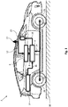
- FIG. 1 shows a schematic diagram of a vehicle 2 with a fusion sensor 4.
- the fusion sensor 4 receives in the present embodiment via a known GNSS receiver 6 position data 8 of the vehicle 2, which include an absolute position of the vehicle 2 on a roadway 10.
- position data 8 from the GNSS receiver 6 also includes a speed of the vehicle 2.
- the position data 8 from the GNSS receivers 6 in the present embodiment are derived in a manner known to those skilled in the art from a GNSS signal 12 in the GNSS receiver 6 which is received via a GNSS antenna 13 and hence referred to below as GNSS position data 8.
- GNSS position data 8 For details, refer to the relevant literature.
- the fusion sensor 4 is designed in a manner to be described to increase the information content of the GNSS position data 8 derived from the GNSS signal 12. This is necessary on the one hand because the GNSS signal 12 has a very low signal / noise band spacing and can thus be very inaccurate. On the other hand, the GNSS signal 12 is not always available.
- the vehicle 2 for this purpose has a movement determination device 14, which detects driving dynamics data 16 of the vehicle 2. These are known to include a longitudinal acceleration, a lateral acceleration and a vertical acceleration and a roll rate, a pitch rate and a yaw rate of the vehicle 2. These driving dynamics data 16 are used in the present embodiment to increase the information content of the GNSS position data 8 and, for example, the position and the Speed of the vehicle 2 on the lane 10 to specify. The refined position data 18 can then be used by a navigation device 20 even if the GNSS signal 12 is not available at all under a tunnel, for example.
- wheel speed sensors 22 which detect the wheel speeds 24 of the individual wheels 26 of the vehicle 2 may optionally also be used in the present embodiment.
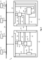
- FIG. 2 Reference is made to a schematic representation of fusion sensor 4 Fig. 1 shows.
- the fusion sensor 4 has a special structure in the present embodiment, to which reference will be made later will be received.
- the data bus 29 can be constructed, for example, as a controller area network bus, called a CAN bus.
- the fusion sensor 4 is to output the specified position data 18.
- the basic idea is to compare the information from the GNSS position data 8 to the vehicle dynamics data 16 from the motion determination device 14 in a filter 30 and thus to increase a signal / noise band spacing in the position data 8 of the GNSS receiver 6 or the vehicle dynamics data 16 from the motion determination device 14 ,
- the filter can be configured as desired, a Kalman filter solves this problem most effectively with a comparatively low computing resource requirement. Therefore, the filter 30 should preferably be a Kalman filter 30 below.
- the calmed-down filter 30 is preceded by the more precise position data 18 of the vehicle 2 and comparison position data 34 of the vehicle 2.
- the more precise position data 18 are in the present embodiment in an example of the DE 10 2006 029 148 A1 known strapdown algorithm 36 generated from the vehicle dynamics data 16. They contain more precise position information about the vehicle 2, but also other position data about the vehicle 2, such as its speed, its acceleration and its heading.
- the comparison position data 34 are obtained from a model 38 of the vehicle 2, which is initially fed from the GNSS receiver 6 with the GNSS position data 8. From this GNSS location data 8, the model 38 then determines the comparison location data 34 which contains the same information as the specified location data 18.
- the more precise Position data 18 and the comparison position data 34 differ only in their values.
- the Kalman filter 30 calculates, based on the refined location data 18 and the comparison location data 34, a fault budget 40 for the refined location data 18 and a fault budget 42 for the comparison location data 34.
- a fault budget is understood to mean a total error in a signal consisting of several Single errors in the acquisition and transmission of the signal composed.
- a corresponding error budget can be composed of errors of the satellite orbit, the satellite clock, the remaining refraction effects and errors in the GNSS receiver 6, for example by returning the fault budget 42 to the GPS Receiver 6 can be corrected by this.
- the error budget 40 of the refined position data 18 and the error budget 42 of the comparison position data 34 are then supplied according to the strapdown algorithm 36 and the model 38 for correcting the specified position data 18 and the comparison position data 34, respectively. That is, the refined location data 18 and the comparison location data 34 are iteratively adjusted for their errors.
- the strapdown algorithm 36 and the Kalman filter 30 are to be executed on a first processor 44 in the form of an algorithm which is a separate processor unit to a second processor 46 on which the model 38 is calculated. For example, if the second processor 46 fails, the refined location data 18 will continue to be output, although this type of refined location data 18 will be subject to greater location tolerance due to the lack of comparison location data 34.
- the second processor 46 in the event of a failure of the first processor 44, the comparison position data 34 as more precise Output situation data 18 in order to continue in such an error case at least the basic functionality of the fusion sensor 4 with the aforementioned larger positional tolerance in the specified position data 18.
- the two processors 44, 46 each have a bus interface 48 via which these measured data 8, 16, 18, 22 can be replaced.
- the two processors 44, 46 each have a direct interface 50 in the present embodiment. Alternatively, however, these data could also be transmitted over the bus 29 with a correspondingly higher transmission latency.
- the two processors 44, 46 are to monitor each other for their faultless operating condition.
- a plausibility algorithm 52 is executed in each processor 44, 46 in the present embodiment.
- Each plausibility algorithm 52 could, for example, plausibilize the refined position data 18 based on the comparison position data 34; in the event of an error, it would not be clear whether the refined position data 18 or the comparison position data 34 are faulty and, accordingly, the first processor 44 or the second processor 46 is subject to a malfunction.
- each plausibility algorithm 52 calculates residuals based on a comparison model (not further described) by inserting the specified position data 18 and / or the comparison position data 34 into the comparison model.
- the first processor 44 could calculate comparison residuals 54 based on the comparison data 34 while the second processor 46 calculates 18 main residuals 56 based on refined location data. Both processors 44, 46 could exchange these residuals 54, 56 for comparison.
- a processor 44, 46 alone or both processors 44, 46 may alternatively or additionally also continuously load the residuals 54, 56 correspondingly calculated based on the position data 18, 34 of the other processor 46, 44 together with their own position data 18, 34 into the bus 29 to allow the receivers of the specified location data 18, such as the navigation device 20, to independently decide based on the residuals 54, 56 which of the location data 18, 34 they use for their own operation.
- the plausibility algorithm 52 can be executed in at least one of the two processors 44, 46 within the framework of a known cryptoprocess, for example to prevent the concealment of performance-enhancing manipulations on the vehicle 2 via manipulations on the plausibility check algorithm 52.
Landscapes
- Engineering & Computer Science (AREA)
- Radar, Positioning & Navigation (AREA)
- Remote Sensing (AREA)
- Physics & Mathematics (AREA)
- General Physics & Mathematics (AREA)
- Automation & Control Theory (AREA)
- Navigation (AREA)
- Traffic Control Systems (AREA)
- Position Fixing By Use Of Radio Waves (AREA)
- Mechanical Engineering (AREA)
Claims (9)
- Dispositif (4) destiné à délivrer un signal de mesure (18) indiquant une grandeur physique de mesure dans un véhicule (2), comprenant :- un premier processeur (44) adapté pour déterminer, sur la base d'un premier signal de capteur (16), un premier signal de comparaison (18) pour la grandeur physique de mesure,- un second processeur (46) adapté pour déterminer, sur la base d'un second signal de capteur (8), un second signal de comparaison (34) pour la grandeur physique de mesure, et- un moyen de filtrage (30) adapté pour déterminer une erreur (40) entre les deux signaux de comparaison (18, 34) et la transmettre au premier processeur (44),- dans lequel le premier processeur (44) est adapté pour déterminer le signal de mesure (18) sur la base d'une correction du premier signal de comparaison (18) contenant l'erreur (40), dans lequel l'un des signaux de capteur (8) est un signal de navigation par satellite global, l'autre des signaux de capteur (16) est un signal de dynamique de conduite et la grandeur physique de mesure (18) est un signal de localisation qui localise le véhicule (2) en ce qui concerne sa position absolue et son changement de position,
caractérisé en ce que les signaux de comparaison sont déterminés sur des processeurs séparés. - Dispositif (4) selon la revendication 1, dans lequel au moins un processeur (44, 46) est adapté pour surveiller l'autre processeur correspondant (46, 44).
- Dispositif (4) selon la revendication 2, dans lequel le processeur de surveillance (44, 46) est adapté pour calculer un résidu (56, 54) entre le signal de comparaison (34, 18) du processeur surveillé (46, 44) et un modèle de la grandeur physique de mesure (18).
- Dispositif (4) selon la revendication 3, dans lequel le processeur de surveillance (44, 46) est adapté pour surveiller le fonctionnement du processeur surveillé (46, 44) sur la base d'une comparaison entre le résidu calculé (56, 54) et une valeur théorique.
- Dispositif (4) selon la revendication 4, dans lequel le processeur de surveillance (44, 46) est adapté pour délivrer son signal de comparaison spécifique (34, 18) en tant que signal de mesure (18) lorsqu'il est détecté que le fonctionnement du processeur surveillé (46, 44) est défectueux.
- Dispositif (4) selon la revendication 5, dans lequel le processeur de surveillance (44, 46) est adapté, en cas de défaillance du processeur surveillé (46, 44), pour fournir un signal de mesure (18) contenant une information (56, 54) concernant la défaillance du processeur surveillé (46, 44).
- Dispositif (4) selon l'une des revendications 3 à 6 précédentes, dans lequel le processeur de surveillance (44, 46) est adapté pour combiner son signal de comparaison (34, 18) avec le résidu calculé (56, 54) et pour le délivrer.
- Dispositif (4) selon l'une des revendications 2 à 7 précédentes, dans lequel le processeur de surveillance (44, 46) est un processeur de cryptage.
- Véhicule (2) comprenant un dispositif (44) selon l'une des revendications précédentes.
Applications Claiming Priority (2)
| Application Number | Priority Date | Filing Date | Title |
|---|---|---|---|
| DE102012224103.5A DE102012224103A1 (de) | 2012-12-20 | 2012-12-20 | Vorrichtung zum Ausgeben eines eine physikalische Messgröße anzeigenden Messsignals |
| PCT/EP2013/076500 WO2014095609A1 (fr) | 2012-12-20 | 2013-12-13 | Dispositif d'émission d'un signal de mesure indiquant une grandeur de mesure physique |
Publications (2)
| Publication Number | Publication Date |
|---|---|
| EP2934952A1 EP2934952A1 (fr) | 2015-10-28 |
| EP2934952B1 true EP2934952B1 (fr) | 2018-08-15 |
Family
ID=49918675
Family Applications (1)
| Application Number | Title | Priority Date | Filing Date |
|---|---|---|---|
| EP13817907.2A Active EP2934952B1 (fr) | 2012-12-20 | 2013-12-13 | Dispositif d'émission d'un signal de mesure indiquant une grandeur de mesure physique |
Country Status (7)
| Country | Link |
|---|---|
| US (1) | US20150330792A1 (fr) |
| EP (1) | EP2934952B1 (fr) |
| JP (1) | JP2016502954A (fr) |
| KR (1) | KR20150093846A (fr) |
| CN (1) | CN104870260B (fr) |
| DE (1) | DE102012224103A1 (fr) |
| WO (1) | WO2014095609A1 (fr) |
Families Citing this family (13)
| Publication number | Priority date | Publication date | Assignee | Title |
|---|---|---|---|---|
| FR3000219B1 (fr) * | 2012-12-26 | 2015-01-09 | Sagem Defense Securite | Procede de comparaison de deux centrales inertielles solidaires d'un meme porteur |
| EP3198304B1 (fr) * | 2014-09-24 | 2023-07-19 | Continental Automotive Technologies GmbH | Concept de key-inbetween pour déterminer les données de position d'un véhicule |
| DE102016201980A1 (de) | 2015-11-12 | 2017-05-18 | Continental Teves Ag & Co. Ohg | System zum Plausibilisieren von Satellitensignalen globaler Navigationssysteme |
| JP6697964B2 (ja) * | 2016-06-27 | 2020-05-27 | 株式会社クボタ | コンバイン |
| US10571913B2 (en) | 2016-08-05 | 2020-02-25 | Aptiv Technologies Limited | Operation-security system for an automated vehicle |
| JP6789159B2 (ja) * | 2017-03-21 | 2020-11-25 | 株式会社ケーヒン | 車両用制御装置 |
| DE102018202296A1 (de) * | 2018-02-15 | 2019-08-22 | Robert Bosch Gmbh | Radarsensor-System und Verfahren zum Betreiben eines Radarsensor-Systems |
| US10776195B2 (en) * | 2018-08-21 | 2020-09-15 | Continental Teves Ag & Co. Ohg | Apparatus for protecting signals |
| CN111025959B (zh) * | 2019-11-20 | 2021-10-01 | 华为技术有限公司 | 一种数据管理的方法、装置、设备及智能汽车 |
| KR102311297B1 (ko) * | 2019-12-10 | 2021-10-15 | 주식회사 이노스코리아 | 센싱 데이터의 유효 여부를 확인하는 전자 장치 및 그 동작 방법 |
| CN111332227B (zh) * | 2020-03-20 | 2021-10-08 | 大陆汽车电子(连云港)有限公司 | 用于机动车的集成传感器装置 |
| CN112765679B (zh) * | 2021-01-08 | 2024-09-10 | 珠海格力电器股份有限公司 | 一种传感器数据管理方法、装置、系统及存储介质 |
| DE102021112332A1 (de) | 2021-05-11 | 2022-11-17 | Bayerische Motoren Werke Aktiengesellschaft | Verfahren zum Erkennen einer unzulässigen Nachricht eines manipulierten Steuergeräts eines Fahrzeugs durch ein zweites Steuergerät des Fahrzeugs, computerlesbares Medium, System, und Fahrzeug |
Family Cites Families (28)
| Publication number | Priority date | Publication date | Assignee | Title |
|---|---|---|---|---|
| US6735506B2 (en) * | 1992-05-05 | 2004-05-11 | Automotive Technologies International, Inc. | Telematics system |
| DE3700986C2 (de) * | 1987-01-15 | 1995-04-20 | Bosch Gmbh Robert | Einrichtung zur Überwachung eines Rechnersystems mit zwei Prozessoren in einem Kraftfahrzeug |
| DE4220247A1 (de) * | 1992-06-20 | 1993-12-23 | Bosch Gmbh Robert | Steuereinrichtung für Fahrzeuge |
| US5654888A (en) * | 1992-06-20 | 1997-08-05 | Robert Bosch Gmbh | Control arrangement for vehicles |
| US5906655A (en) * | 1997-04-02 | 1999-05-25 | Caterpillar Inc. | Method for monitoring integrity of an integrated GPS and INU system |
| KR100366716B1 (ko) * | 1998-10-13 | 2003-01-06 | 가부시키가이샤 자나비 인포메틱스 | 방송형 정보제공 시스템 및 주행환경 정보수집 장치 |
| US6453238B1 (en) * | 1999-09-16 | 2002-09-17 | Sirf Technology, Inc. | Navigation system and method for tracking the position of an object |
| CN1441912A (zh) * | 2000-05-09 | 2003-09-10 | 先进导航及定位公司 | 运载工具监视系统 |
| JP4399987B2 (ja) * | 2001-01-25 | 2010-01-20 | 株式会社デンソー | 車両統合制御におけるフェイルセーフシステム |
| CA2484901A1 (fr) * | 2002-05-07 | 2003-12-18 | Argo-Tech Corporation | Systeme de suivi et procede associe |
| JP2005178627A (ja) * | 2003-12-19 | 2005-07-07 | Toyota Motor Corp | 車両の統合制御システム |
| DE102004052860A1 (de) * | 2004-10-26 | 2006-04-27 | Volkswagen Ag | Vorrichtung und Verfahren zur Übertragung von Sensorsignalen |
| WO2007143806A2 (fr) * | 2006-06-15 | 2007-12-21 | Uti Limited Partnership | Système de navigation et de positionnement véhiculaire |
| DE102006029148B4 (de) | 2006-06-24 | 2010-08-05 | Lfk-Lenkflugkörpersysteme Gmbh | Verfahren zur Überprüfung einer inertialen Messeinheit von Fahrzeugen, insbesondere von Luftfahrzeugen, im stationären Zustand |
| US20080071476A1 (en) * | 2006-09-19 | 2008-03-20 | Takayuki Hoshizaki | Vehicle dynamics conditioning method on MEMS based integrated INS/GPS vehicle navigation system |
| US20080077325A1 (en) * | 2006-09-25 | 2008-03-27 | Honeywell International Inc. | Systems and methods for a hybrid transition matrix |
| JP2008247053A (ja) * | 2007-03-29 | 2008-10-16 | Honda Motor Co Ltd | 車両の制御装置 |
| DE102008015232A1 (de) * | 2007-11-15 | 2009-05-20 | Continental Teves Ag & Co. Ohg | Übertragung von Fahrzeuginformation |
| FR2927419B1 (fr) * | 2008-02-08 | 2010-06-11 | Roulements Soc Nouvelle | Procede d'estimation des composantes du torseur d'efforts s'appliquant sur un palier |
| JP5270184B2 (ja) * | 2008-02-13 | 2013-08-21 | 古野電気株式会社 | 衛星航法/推測航法統合測位装置 |
| DE102010063984A1 (de) | 2010-02-11 | 2011-08-11 | Continental Teves AG & Co. OHG, 60488 | Fahrzeug-Sensor-Knoten |
| US8577607B2 (en) * | 2010-09-13 | 2013-11-05 | California Institute Of Technology | GPS/INS sensor fusion using GPS wind up model |
| US20130145401A1 (en) * | 2011-11-16 | 2013-06-06 | Flextronics Ap, Llc | Music streaming |
| JP5842363B2 (ja) * | 2011-04-01 | 2016-01-13 | セイコーエプソン株式会社 | 位置算出方法及び位置算出装置 |
| US8494585B2 (en) * | 2011-10-13 | 2013-07-23 | The Boeing Company | Portable communication devices with accessory functions and related methods |
| US8996310B1 (en) * | 2012-03-08 | 2015-03-31 | Moog, Inc. | Vehicle heading validation using inertial measurement unit |
| US20140022121A1 (en) * | 2012-07-17 | 2014-01-23 | Lockheed Martin Corporation | Navigating in areas of uncertain positioning data |
| US8972166B2 (en) * | 2012-07-17 | 2015-03-03 | Lockheed Martin Corporation | Proactive mitigation of navigational uncertainty |
-
2012
- 2012-12-20 DE DE102012224103.5A patent/DE102012224103A1/de not_active Withdrawn
-
2013
- 2013-12-13 KR KR1020157019325A patent/KR20150093846A/ko not_active Withdrawn
- 2013-12-13 WO PCT/EP2013/076500 patent/WO2014095609A1/fr not_active Ceased
- 2013-12-13 US US14/651,288 patent/US20150330792A1/en not_active Abandoned
- 2013-12-13 JP JP2015547043A patent/JP2016502954A/ja active Pending
- 2013-12-13 CN CN201380066601.6A patent/CN104870260B/zh active Active
- 2013-12-13 EP EP13817907.2A patent/EP2934952B1/fr active Active
Non-Patent Citations (1)
| Title |
|---|
| None * |
Also Published As
| Publication number | Publication date |
|---|---|
| KR20150093846A (ko) | 2015-08-18 |
| WO2014095609A1 (fr) | 2014-06-26 |
| EP2934952A1 (fr) | 2015-10-28 |
| DE102012224103A1 (de) | 2014-06-26 |
| CN104870260B (zh) | 2017-09-12 |
| JP2016502954A (ja) | 2016-02-01 |
| US20150330792A1 (en) | 2015-11-19 |
| CN104870260A (zh) | 2015-08-26 |
Similar Documents
| Publication | Publication Date | Title |
|---|---|---|
| EP2934952B1 (fr) | Dispositif d'émission d'un signal de mesure indiquant une grandeur de mesure physique | |
| EP2534011B1 (fr) | Capteur noeuds pour un véhicule | |
| DE102011008608B4 (de) | Verfahren zum überwachen der ausrichtung von rädern unter verwendung von gps | |
| EP2795345B1 (fr) | Procédé et dispositif pour la détermination de la position de montage d'un module capteur dans un véhicule et véhicule doté d'un tel dispositif | |
| EP3155374B1 (fr) | Procédé et système d'initialisation d'un système de fusion de capteurs | |
| EP2005120B1 (fr) | Procédé et dispositif de détermination de la valeur absolue d'une grandeur | |
| DE102014220781A1 (de) | Ausfallsichere E/E-Architektur für automatisiertes Fahren | |
| DE10162689A1 (de) | Vorrichtung zur Überwachung von in einem Fahrzeug angeordneten Sensormitteln | |
| WO2015075093A1 (fr) | Procédé, filtre de fusion et système de fusion de signaux de détection avec différents retards de sortie de signal pour former un jeu de données de fusion | |
| WO2005080164A1 (fr) | Procede et dispositif pour controler des unites de traitement de signaux pour des detecteurs | |
| DE102015108286A1 (de) | Redundanz für automatischen Fahrzeugbetrieb | |
| EP3155454B1 (fr) | Procédé et système d'adaptation d'un système de navigation | |
| DE102011110012A1 (de) | Diagnoseverfahren zur Verwendung mit einem dynamischen Fahrzeugsteuersystem (VDCS) | |
| DE102020110528B4 (de) | Kamerasignalüberwachungsvorrichtung und -verfahren | |
| DE112019007286B4 (de) | Fahrzeuginterne steuerungsvorrichtung und fahrzeuginternes steuerungssystem | |
| DE102016114366B4 (de) | Ausfallsicheres inertiales messeinheitssystem reduzierter ordnung | |
| DE102021206379A1 (de) | Steuereinrichtung sowie Assistenzsystem für ein Fahrzeug | |
| DE112018005815B4 (de) | Steuereinrichtung und elektronisches Steuersystem für Fahrzeuge | |
| DE102017220788A1 (de) | Verfahren zum Trainieren eines zentralen Künstlichen-Intelligenz-Moduls | |
| EP3155373A1 (fr) | Procédé et système d'adaptation d'un système de navigation | |
| DE102010006178B4 (de) | Verfahren zur Überwachung eines Reifendrucks und Reifendruckkontrolleinrichtung | |
| DE102014211178A1 (de) | Verfahren und System zur Korrektur von Messdaten eines ersten Sensorsystems | |
| EP2755831B1 (fr) | Procédé permettant de filtrer des données dans un système de contrôle de pression des pneus d'un véhicule | |
| WO2016041963A1 (fr) | Localisation redondante au moyen d'un signal gnss | |
| WO2011110382A1 (fr) | Procédé et dispositif de détection d'un écart d'un signal de vitesse de rotation d'un capteur de vitesse de rotation |
Legal Events
| Date | Code | Title | Description |
|---|---|---|---|
| PUAI | Public reference made under article 153(3) epc to a published international application that has entered the european phase |
Free format text: ORIGINAL CODE: 0009012 |
|
| 17P | Request for examination filed |
Effective date: 20150720 |
|
| AK | Designated contracting states |
Kind code of ref document: A1 Designated state(s): AL AT BE BG CH CY CZ DE DK EE ES FI FR GB GR HR HU IE IS IT LI LT LU LV MC MK MT NL NO PL PT RO RS SE SI SK SM TR |
|
| AX | Request for extension of the european patent |
Extension state: BA ME |
|
| DAX | Request for extension of the european patent (deleted) | ||
| GRAP | Despatch of communication of intention to grant a patent |
Free format text: ORIGINAL CODE: EPIDOSNIGR1 |
|
| INTG | Intention to grant announced |
Effective date: 20180502 |
|
| GRAS | Grant fee paid |
Free format text: ORIGINAL CODE: EPIDOSNIGR3 |
|
| GRAA | (expected) grant |
Free format text: ORIGINAL CODE: 0009210 |
|
| AK | Designated contracting states |
Kind code of ref document: B1 Designated state(s): AL AT BE BG CH CY CZ DE DK EE ES FI FR GB GR HR HU IE IS IT LI LT LU LV MC MK MT NL NO PL PT RO RS SE SI SK SM TR |
|
| REG | Reference to a national code |
Ref country code: CH Ref legal event code: EP Ref country code: GB Ref legal event code: FG4D Free format text: NOT ENGLISH Ref country code: AT Ref legal event code: REF Ref document number: 1029369 Country of ref document: AT Kind code of ref document: T Effective date: 20180815 |
|
| REG | Reference to a national code |
Ref country code: IE Ref legal event code: FG4D Free format text: LANGUAGE OF EP DOCUMENT: GERMAN |
|
| REG | Reference to a national code |
Ref country code: DE Ref legal event code: R096 Ref document number: 502013010892 Country of ref document: DE |
|
| RAP2 | Party data changed (patent owner data changed or rights of a patent transferred) |
Owner name: CONTINENTAL TEVES AG & CO. OHG |
|
| REG | Reference to a national code |
Ref country code: NL Ref legal event code: MP Effective date: 20180815 |
|
| REG | Reference to a national code |
Ref country code: LT Ref legal event code: MG4D |
|
| PG25 | Lapsed in a contracting state [announced via postgrant information from national office to epo] |
Ref country code: RS Free format text: LAPSE BECAUSE OF FAILURE TO SUBMIT A TRANSLATION OF THE DESCRIPTION OR TO PAY THE FEE WITHIN THE PRESCRIBED TIME-LIMIT Effective date: 20180815 Ref country code: FI Free format text: LAPSE BECAUSE OF FAILURE TO SUBMIT A TRANSLATION OF THE DESCRIPTION OR TO PAY THE FEE WITHIN THE PRESCRIBED TIME-LIMIT Effective date: 20180815 Ref country code: GR Free format text: LAPSE BECAUSE OF FAILURE TO SUBMIT A TRANSLATION OF THE DESCRIPTION OR TO PAY THE FEE WITHIN THE PRESCRIBED TIME-LIMIT Effective date: 20181116 Ref country code: NO Free format text: LAPSE BECAUSE OF FAILURE TO SUBMIT A TRANSLATION OF THE DESCRIPTION OR TO PAY THE FEE WITHIN THE PRESCRIBED TIME-LIMIT Effective date: 20181115 Ref country code: BG Free format text: LAPSE BECAUSE OF FAILURE TO SUBMIT A TRANSLATION OF THE DESCRIPTION OR TO PAY THE FEE WITHIN THE PRESCRIBED TIME-LIMIT Effective date: 20181115 Ref country code: SE Free format text: LAPSE BECAUSE OF FAILURE TO SUBMIT A TRANSLATION OF THE DESCRIPTION OR TO PAY THE FEE WITHIN THE PRESCRIBED TIME-LIMIT Effective date: 20180815 Ref country code: IS Free format text: LAPSE BECAUSE OF FAILURE TO SUBMIT A TRANSLATION OF THE DESCRIPTION OR TO PAY THE FEE WITHIN THE PRESCRIBED TIME-LIMIT Effective date: 20181215 Ref country code: LT Free format text: LAPSE BECAUSE OF FAILURE TO SUBMIT A TRANSLATION OF THE DESCRIPTION OR TO PAY THE FEE WITHIN THE PRESCRIBED TIME-LIMIT Effective date: 20180815 Ref country code: NL Free format text: LAPSE BECAUSE OF FAILURE TO SUBMIT A TRANSLATION OF THE DESCRIPTION OR TO PAY THE FEE WITHIN THE PRESCRIBED TIME-LIMIT Effective date: 20180815 |
|
| PG25 | Lapsed in a contracting state [announced via postgrant information from national office to epo] |
Ref country code: HR Free format text: LAPSE BECAUSE OF FAILURE TO SUBMIT A TRANSLATION OF THE DESCRIPTION OR TO PAY THE FEE WITHIN THE PRESCRIBED TIME-LIMIT Effective date: 20180815 Ref country code: AL Free format text: LAPSE BECAUSE OF FAILURE TO SUBMIT A TRANSLATION OF THE DESCRIPTION OR TO PAY THE FEE WITHIN THE PRESCRIBED TIME-LIMIT Effective date: 20180815 Ref country code: LV Free format text: LAPSE BECAUSE OF FAILURE TO SUBMIT A TRANSLATION OF THE DESCRIPTION OR TO PAY THE FEE WITHIN THE PRESCRIBED TIME-LIMIT Effective date: 20180815 |
|
| PG25 | Lapsed in a contracting state [announced via postgrant information from national office to epo] |
Ref country code: RO Free format text: LAPSE BECAUSE OF FAILURE TO SUBMIT A TRANSLATION OF THE DESCRIPTION OR TO PAY THE FEE WITHIN THE PRESCRIBED TIME-LIMIT Effective date: 20180815 Ref country code: CZ Free format text: LAPSE BECAUSE OF FAILURE TO SUBMIT A TRANSLATION OF THE DESCRIPTION OR TO PAY THE FEE WITHIN THE PRESCRIBED TIME-LIMIT Effective date: 20180815 Ref country code: PL Free format text: LAPSE BECAUSE OF FAILURE TO SUBMIT A TRANSLATION OF THE DESCRIPTION OR TO PAY THE FEE WITHIN THE PRESCRIBED TIME-LIMIT Effective date: 20180815 Ref country code: ES Free format text: LAPSE BECAUSE OF FAILURE TO SUBMIT A TRANSLATION OF THE DESCRIPTION OR TO PAY THE FEE WITHIN THE PRESCRIBED TIME-LIMIT Effective date: 20180815 Ref country code: EE Free format text: LAPSE BECAUSE OF FAILURE TO SUBMIT A TRANSLATION OF THE DESCRIPTION OR TO PAY THE FEE WITHIN THE PRESCRIBED TIME-LIMIT Effective date: 20180815 Ref country code: IT Free format text: LAPSE BECAUSE OF FAILURE TO SUBMIT A TRANSLATION OF THE DESCRIPTION OR TO PAY THE FEE WITHIN THE PRESCRIBED TIME-LIMIT Effective date: 20180815 |
|
| REG | Reference to a national code |
Ref country code: DE Ref legal event code: R097 Ref document number: 502013010892 Country of ref document: DE |
|
| PG25 | Lapsed in a contracting state [announced via postgrant information from national office to epo] |
Ref country code: DK Free format text: LAPSE BECAUSE OF FAILURE TO SUBMIT A TRANSLATION OF THE DESCRIPTION OR TO PAY THE FEE WITHIN THE PRESCRIBED TIME-LIMIT Effective date: 20180815 Ref country code: SM Free format text: LAPSE BECAUSE OF FAILURE TO SUBMIT A TRANSLATION OF THE DESCRIPTION OR TO PAY THE FEE WITHIN THE PRESCRIBED TIME-LIMIT Effective date: 20180815 Ref country code: SK Free format text: LAPSE BECAUSE OF FAILURE TO SUBMIT A TRANSLATION OF THE DESCRIPTION OR TO PAY THE FEE WITHIN THE PRESCRIBED TIME-LIMIT Effective date: 20180815 |
|
| PLBE | No opposition filed within time limit |
Free format text: ORIGINAL CODE: 0009261 |
|
| STAA | Information on the status of an ep patent application or granted ep patent |
Free format text: STATUS: NO OPPOSITION FILED WITHIN TIME LIMIT |
|
| 26N | No opposition filed |
Effective date: 20190516 |
|
| REG | Reference to a national code |
Ref country code: CH Ref legal event code: PL |
|
| GBPC | Gb: european patent ceased through non-payment of renewal fee |
Effective date: 20181213 |
|
| PG25 | Lapsed in a contracting state [announced via postgrant information from national office to epo] |
Ref country code: SI Free format text: LAPSE BECAUSE OF FAILURE TO SUBMIT A TRANSLATION OF THE DESCRIPTION OR TO PAY THE FEE WITHIN THE PRESCRIBED TIME-LIMIT Effective date: 20180815 Ref country code: LU Free format text: LAPSE BECAUSE OF NON-PAYMENT OF DUE FEES Effective date: 20181213 Ref country code: MC Free format text: LAPSE BECAUSE OF FAILURE TO SUBMIT A TRANSLATION OF THE DESCRIPTION OR TO PAY THE FEE WITHIN THE PRESCRIBED TIME-LIMIT Effective date: 20180815 |
|
| REG | Reference to a national code |
Ref country code: IE Ref legal event code: MM4A |
|
| REG | Reference to a national code |
Ref country code: BE Ref legal event code: MM Effective date: 20181231 |
|
| PG25 | Lapsed in a contracting state [announced via postgrant information from national office to epo] |
Ref country code: IE Free format text: LAPSE BECAUSE OF NON-PAYMENT OF DUE FEES Effective date: 20181213 |
|
| PG25 | Lapsed in a contracting state [announced via postgrant information from national office to epo] |
Ref country code: BE Free format text: LAPSE BECAUSE OF NON-PAYMENT OF DUE FEES Effective date: 20181231 |
|
| PG25 | Lapsed in a contracting state [announced via postgrant information from national office to epo] |
Ref country code: CH Free format text: LAPSE BECAUSE OF NON-PAYMENT OF DUE FEES Effective date: 20181231 Ref country code: LI Free format text: LAPSE BECAUSE OF NON-PAYMENT OF DUE FEES Effective date: 20181231 Ref country code: GB Free format text: LAPSE BECAUSE OF NON-PAYMENT OF DUE FEES Effective date: 20181213 |
|
| PG25 | Lapsed in a contracting state [announced via postgrant information from national office to epo] |
Ref country code: MT Free format text: LAPSE BECAUSE OF FAILURE TO SUBMIT A TRANSLATION OF THE DESCRIPTION OR TO PAY THE FEE WITHIN THE PRESCRIBED TIME-LIMIT Effective date: 20180815 |
|
| REG | Reference to a national code |
Ref country code: AT Ref legal event code: MM01 Ref document number: 1029369 Country of ref document: AT Kind code of ref document: T Effective date: 20181213 |
|
| PG25 | Lapsed in a contracting state [announced via postgrant information from national office to epo] |
Ref country code: TR Free format text: LAPSE BECAUSE OF FAILURE TO SUBMIT A TRANSLATION OF THE DESCRIPTION OR TO PAY THE FEE WITHIN THE PRESCRIBED TIME-LIMIT Effective date: 20180815 |
|
| PG25 | Lapsed in a contracting state [announced via postgrant information from national office to epo] |
Ref country code: AT Free format text: LAPSE BECAUSE OF NON-PAYMENT OF DUE FEES Effective date: 20181213 |
|
| PG25 | Lapsed in a contracting state [announced via postgrant information from national office to epo] |
Ref country code: PT Free format text: LAPSE BECAUSE OF FAILURE TO SUBMIT A TRANSLATION OF THE DESCRIPTION OR TO PAY THE FEE WITHIN THE PRESCRIBED TIME-LIMIT Effective date: 20180815 |
|
| PG25 | Lapsed in a contracting state [announced via postgrant information from national office to epo] |
Ref country code: MK Free format text: LAPSE BECAUSE OF NON-PAYMENT OF DUE FEES Effective date: 20180815 Ref country code: HU Free format text: LAPSE BECAUSE OF FAILURE TO SUBMIT A TRANSLATION OF THE DESCRIPTION OR TO PAY THE FEE WITHIN THE PRESCRIBED TIME-LIMIT; INVALID AB INITIO Effective date: 20131213 Ref country code: CY Free format text: LAPSE BECAUSE OF FAILURE TO SUBMIT A TRANSLATION OF THE DESCRIPTION OR TO PAY THE FEE WITHIN THE PRESCRIBED TIME-LIMIT Effective date: 20180815 |
|
| REG | Reference to a national code |
Ref country code: DE Ref legal event code: R081 Ref document number: 502013010892 Country of ref document: DE Owner name: CONTINENTAL AUTOMOTIVE TECHNOLOGIES GMBH, DE Free format text: FORMER OWNER: CONTINENTAL TEVES AG & CO. OHG, 60488 FRANKFURT, DE Ref country code: DE Ref legal event code: R081 Ref document number: 502013010892 Country of ref document: DE Owner name: AUMOVIO GERMANY GMBH, DE Free format text: FORMER OWNER: CONTINENTAL TEVES AG & CO. OHG, 60488 FRANKFURT, DE |
|
| REG | Reference to a national code |
Ref country code: DE Ref legal event code: R081 Ref document number: 502013010892 Country of ref document: DE Owner name: CONTINENTAL AUTOMOTIVE TECHNOLOGIES GMBH, DE Free format text: FORMER OWNER: CONTINENTAL AUTOMOTIVE TECHNOLOGIES GMBH, 30165 HANNOVER, DE Ref country code: DE Ref legal event code: R081 Ref document number: 502013010892 Country of ref document: DE Owner name: AUMOVIO GERMANY GMBH, DE Free format text: FORMER OWNER: CONTINENTAL AUTOMOTIVE TECHNOLOGIES GMBH, 30165 HANNOVER, DE |
|
| PGFP | Annual fee paid to national office [announced via postgrant information from national office to epo] |
Ref country code: FR Payment date: 20251223 Year of fee payment: 13 |
|
| REG | Reference to a national code |
Ref country code: DE Ref legal event code: R081 Ref document number: 502013010892 Country of ref document: DE Owner name: AUMOVIO GERMANY GMBH, DE Free format text: FORMER OWNER: CONTINENTAL AUTOMOTIVE TECHNOLOGIES GMBH, 30175 HANNOVER, DE |
|
| PGFP | Annual fee paid to national office [announced via postgrant information from national office to epo] |
Ref country code: DE Payment date: 20251231 Year of fee payment: 13 |