EP2935018B1 - Vorrichtung zur identifizierung und ansammlung von gegenständen - Google Patents
Vorrichtung zur identifizierung und ansammlung von gegenständen Download PDFInfo
- Publication number
- EP2935018B1 EP2935018B1 EP15707773.6A EP15707773A EP2935018B1 EP 2935018 B1 EP2935018 B1 EP 2935018B1 EP 15707773 A EP15707773 A EP 15707773A EP 2935018 B1 EP2935018 B1 EP 2935018B1
- Authority
- EP
- European Patent Office
- Prior art keywords
- pushing plate
- articles
- region
- accumulating
- detecting
- Prior art date
- Legal status (The legal status is an assumption and is not a legal conclusion. Google has not performed a legal analysis and makes no representation as to the accuracy of the status listed.)
- Not-in-force
Links
- 230000003287 optical effect Effects 0.000 claims description 53
- 230000037361 pathway Effects 0.000 claims description 28
- 238000012856 packing Methods 0.000 claims description 5
- 239000012780 transparent material Substances 0.000 description 9
- 238000001514 detection method Methods 0.000 description 5
- VVQNEPGJFQJSBK-UHFFFAOYSA-N Methyl methacrylate Chemical compound COC(=O)C(C)=C VVQNEPGJFQJSBK-UHFFFAOYSA-N 0.000 description 2
- 229920005372 Plexiglas® Polymers 0.000 description 2
- 238000006073 displacement reaction Methods 0.000 description 1
- 239000000463 material Substances 0.000 description 1
- 238000004806 packaging method and process Methods 0.000 description 1
- 238000006748 scratching Methods 0.000 description 1
- 230000002393 scratching effect Effects 0.000 description 1
- 230000000007 visual effect Effects 0.000 description 1
Images



Classifications
-
- B—PERFORMING OPERATIONS; TRANSPORTING
- B65—CONVEYING; PACKING; STORING; HANDLING THIN OR FILAMENTARY MATERIAL
- B65B—MACHINES, APPARATUS OR DEVICES FOR, OR METHODS OF, PACKAGING ARTICLES OR MATERIALS; UNPACKING
- B65B35/00—Supplying, feeding, arranging or orientating articles to be packaged
- B65B35/30—Arranging and feeding articles in groups
- B65B35/40—Arranging and feeding articles in groups by reciprocating or oscillatory pushers
-
- B—PERFORMING OPERATIONS; TRANSPORTING
- B65—CONVEYING; PACKING; STORING; HANDLING THIN OR FILAMENTARY MATERIAL
- B65B—MACHINES, APPARATUS OR DEVICES FOR, OR METHODS OF, PACKAGING ARTICLES OR MATERIALS; UNPACKING
- B65B5/00—Packaging individual articles in containers or receptacles, e.g. bags, sacks, boxes, cartons, cans, jars
- B65B5/10—Filling containers or receptacles progressively or in stages by introducing successive articles, or layers of articles
- B65B5/106—Filling containers or receptacles progressively or in stages by introducing successive articles, or layers of articles by pushers
-
- B—PERFORMING OPERATIONS; TRANSPORTING
- B65—CONVEYING; PACKING; STORING; HANDLING THIN OR FILAMENTARY MATERIAL
- B65B—MACHINES, APPARATUS OR DEVICES FOR, OR METHODS OF, PACKAGING ARTICLES OR MATERIALS; UNPACKING
- B65B65/00—Details peculiar to packaging machines and not otherwise provided for; Arrangements of such details
- B65B65/08—Devices for counting or registering the number of articles handled, or the number of packages produced by the machine
Definitions
- the present invention relates to the technical sector of packing articles; more in particular, the invention concerns an identifying and accumulating device of articles.
- a device of known type for identifying and accumulating articles is usually present in a machine for packing articles, for example a boxing machine.
- the known device (D) mentioned above, illustrated by way of example in figure 1 comprises:
- the detecting region (3) is interposed between the accumulating region (5) and the television camera (4) is aligned to the accumulating region (5) and to the television camera (4).
- the device (D) further comprises:
- the pushing plate (81), made of a transparent material, is drawn by the carriage (7) along a straight advancement pathway from a retracted position (the situation in figure 1 ), in which the pushing plate (81) is interposed between the detecting region (3) and the television camera (4), to an advanced position in which the pushing plate (81) is located in the accumulating region (5).
- the television camera (4) detects the identifying code of each article (A) which forms the stack.
- the pushing plate (81) is made of a transparent material (for example Plexiglass).
- the pushing plate (81) is moved along the straight advancement pathway, so as to push the stack of articles (A) from the detecting region (3) into the accumulating region (5).
- the pushing plate is made of a transparent material, correct detecting of the identifying codes of the articles by the television cameras is not guaranteed.
- the pushing plate made of transparent material for example Plexiglass
- damage such as scratching, splintering, etc.
- the presence of damage to the pushing plate and/or light reflections can even significantly obstruct the detection of the identifying codes of the articles by the television camera.
- EP 0 959 002 A1 discloses a packing machine having a pushing plate for pushing stacks of products.
- the aim of the present invention is to obviate the above-mentioned drawbacks.
- the device of the invention advantageously enables, in any situation, a correct detection of the identifying codes of the articles, differently to the prior art.
- excellent detection of the identifying codes of the articles is still guaranteed.
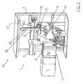
- numerals 1, 10 and 100 denote an identifying and accumulating device of articles (A) according to different embodiments of the present invention.
- the articles (A) are provided with an identifying code (for example a standardized GS1 code, such as Barcode, Datamatrix, etc.).
- the device (1) comprises: a frame (2); a detecting region (3), in which the articles (A) are positioned in a row in such a way that the relative identifying code is arranged at a side (L) of the row; optical detecting means (4) arranged in proximity of the detecting region (3) for detecting the identifying code of the articles (A) when the articles (A) are arranged in the detecting region (3).
- the device (1) further comprises: an accumulating region (5) in which the articles (A) coming from the detecting region (3) are accumulated so as to be subsequently packed; in particular, the detecting region (3) is interposed between the accumulating region (5) and the optical detecting means (4) and is aligned to the accumulating region (5) and the optical detecting means (4).
- the detecting region (3), the accumulating region (5) and the optical detecting means (4) are arranged along a line.
- the device (1) comprises a linear guide (6, 60, 61) fixed to the frame (2), a carriage (7) that is mobile along the linear guide (6, 60, 61); and a pusher (8) borne by the carriage (7), comprising a connecting arm (80) constrained to the carriage (7) and a pushing plate (81) which is borne by the connecting arm (80).
- the pushing plate (81) is dimensioned so as to push the articles (A) from the detecting region (3) to the accumulating region (5).
- the pushing plate (81) is drawn by the carriage (7) along a straight advancing pathway from a retracted position, in which the pushing plate (81) is interposed between the detecting region (3) and the optical detecting means (4) and wherein the pushing plate (81) is aligned with the detecting region (3) and the optical detecting means (4), to an advanced position in which the pushing plate (81) is at the accumulating region (5).
- the pusher (8) further comprises movement means (900) for moving the connecting arm (80) and the pushing plate (81) with respect to the carriage (7), which movement means (900) enable displacing the pushing plate (81) out of the straight advancement pathway in order that the optical detecting means (4) face the articles (A) arranged in a row in the detecting region (3) so as to detect the relative identifying code (this situation is illustrated in figure 2-5 ).
- the pushing plate (81) is brought out of the straight pathway, thus enabling the optical means (which for example comprise a television camera (4) or a photographic camera) to optimally and completely detect the identifying codes of the articles (A) in the detecting region (3).
- the optical means which for example comprise a television camera (4) or a photographic camera
- the pushing plate was made of a transparent material and was constrained to carry out only the straight advancement path described above: in fact, the connecting arm was unremovably fixed to the carriage. During the identifying operation of the articles, therefore, the pushing plate was aligned to the articles and to the optical detecting means and interposed between the articles and the optical detecting means.
- the connecting arm was not made of a transparent material and thus at least partly encroached upon the field of vision of the television camera. In this way the detecting of the identifying codes was only partial.
- the fact that the connecting arm (80) is mobile with respect to the carriage (7) enables taking the connecting arm (80) out of the field of vision of the optical detecting means (4), and thus enabling a complete detecting of the identifying codes of the articles (A) by the optical detecting means (4).
- the pushing plate (81) of the device (1) is taken out of the straight advancement pathway during the detecting of the identifying codes by the optical detecting means (4), there is no requirement for it to be made of a transparent material, i.e. it can be made of an opaque material.
- the articles (A) can be positioned in the detecting region (3) in a stack (i.e. in a plurality of rows) as in the case illustrated in the accompanying figures.
- the pushing plate (81) is brought out of the straight advancing pathway and the optical detecting means (4) can detect the identifying code of the articles (A), directly facing the side (L) of the row of articles (A).
- the optical detecting means (4) can detect the identifying code of the articles (A), directly facing the side (L) of the row of articles (A).
- the pushing plate (81) is moved along the straight advancement pathway, so as to push the articles (A) from the detecting region (3) into the accumulating region (5).
- the accumulating region (5) can comprise, for example, two guide and containing walls (50), facing one another, as in the illustrated case, between which the articles (A) are arranged, pushed by the pusher (8), before being packed.
- a carton (C) can be present, with the opening thereof facing and turned towards the accumulating region (5).
- the connecting arm (80) comprises a portion (82) that is transversal to the straight advancement pathway; further, in this variant, the movement means (900) comprise: a motor mounted on-board the carriage (7); a pinion (91) activated in rotation by the motor; and a rack (92) which is fixed to the portion (82) of the connecting arm (80) and which engages with the pinion (91) so that the connecting arm (80) and the pushing plate (81) are further mobile in a direction that is transversal to the straight advancement pathway.
- the variant is advantageously particularly compact. In fact the movement of the connecting arm (80) and pushing plate (81) in a transversal direction with respect to the straight advancement pathway in no way interferes with the identifying and accumulating operations of the articles (A).
- the portion (82) of the connecting arm (80) can be perpendicular to the straight advancement pathway (as in the case of figure 2 ).
- the overall size of the device (1) is further reduced.
- the displacement of the connecting arm (80) and the pushing plate (81) is vertical, vastly reducing the space required for moving the connecting arm (80) and the pushing plate (81).
- the movement means (900) comprise a motor (901) (visible in figure 4 ) mounted on-board the carriage (7), the output shaft (93) (also visible in figure 4 ) of which commands rotation of the connecting arm (80) and the pushing plate (81).
- the connecting arm (80) is hinged to the carriage (7).
- the motor (901) is fixed to the carriage (7) and the output shaft (93) of the motor (901) can be arranged such as to be parallel to the straight pathway (this is the case of figure 3 ).
- the output shaft (93) of the motor (901) can be arranged such as to be transversal (for example perpendicular) to the straight pathway (the case of figure 4 ).
- the device (1) comprises two linear guides (60, 61), first (60) and second (61), parallel to one another to which the carriage (7) is constrained and along which the carriage (7) can slide.
- the carriage (7) comprises a transversal portion (70) (for example perpendicular) to the linear guides (60, 61) along which the connecting arm (80) can slide.
- the connecting arm (80) is constrained by the carriage (7) and is arranged in a first position at the first linear guide (60).
- the movement means in this case enable translation of the connecting arm (80) (and consequently of the pushing plate (81) along the transversal portion (70) of the carriage (7) into a second position at the second linear guide (61) (the situation illustrated in figure 5 ), enabling the optical detecting means (4) to detect the identifying codes of the articles (A).
- the connecting arm (80) has an L-shaped configuration, i.e. it exhibits a first portion (82) that is perpendicular to the straight advancement pathway and a second portion that is perpendicular to the first portion (i.e. parallel to the straight advancement pathway) and connected to the first portion (see for example figure 2 ).
- the device comprises: a detecting region (3) in which the articles (A) are positioned in a row such that the relative identifying code is arranged at a side (L) of the row; optical detecting means (4) (which for example comprise a television camera or a photographic camera) for detecting the identifying code of the articles (A) when the articles (A) are arranged in the detecting region (3).
- optical detecting means (4) which for example comprise a television camera or a photographic camera
- the device (100) further comprises: an accumulating region (5) in which the articles (A) coming from the detecting region (3) are to be accumulated in order to be successively packed; the detecting region (3) is interposed between the accumulating region (5) and the optical detecting means (4) and is aligned to the accumulating region (5) and to the optical detecting means (4).
- the device (100) further comprises a pusher (8) for pushing the articles (A) from the detecting region (3) to the accumulating region (5), comprising a pushing plate (81) which is mobile along a straight pathway from a retracted position (see figures 7 and 7A ), in which the pushing plate (81) is aligned with the optical detecting means (4) and faces a side (L) of the row of articles (A) arranged in the detecting region (3), to an advanced position in which the pushing plate (81) is at the accumulating region (5), and vice versa.
- a pusher (8) for pushing the articles (A) from the detecting region (3) to the accumulating region (5) comprising a pushing plate (81) which is mobile along a straight pathway from a retracted position (see figures 7 and 7A ), in which the pushing plate (81) is aligned with the optical detecting means (4) and faces a side (L) of the row of articles (A) arranged in the detecting region (3), to an advanced position in which the pushing plate (81) is
- the pushing plate (81) comprises a through-opening (9), and the pusher (8) comprises a closing element (90) dimensioned such as to close the through-opening (9) of the pushing plate (81).
- the closing element (90) is constrained to the pushing plate (81) so as to be mobile between two configurations: a first configuration in which it is arranged in the through-opening (9), closes the through-opening (9) and defines, with the pushing plate (81), a pushing surface (S) for pushing the articles (A) from the detecting region (3) to the accumulating region (5) when the pushing plate (81) is moved into the advanced position (see figures 6, 6A ); and a second configuration in which it makes the through-opening (9) accessible (see figures 7, 7A ).
- the through-opening (9) is arranged and dimensioned such that, when the pushing plate is in the retracted position and the closing element (90) is moved into the second configuration, the optical detecting means (4) are facing towards the through-opening (9) and, through the through-opening (9), face the articles (A) arranged in the detecting region (3), in such a way as to detect the relative identifying code thereof (see figures 7, 7A ).
- optical detecting means (4) are advantageously in no way obstructed in detecting the identifying code of the articles (A), as the presence of the through-opening (9) of the pushing plate (81) enables completely freeing the visual field of the optical detecting means (4).
- the optical detecting means (4) are at the through-opening (9) (i.e. into the through-opening (9), see the detail of figures 7, 7A ).
- the retracted position of the pusher plate (81) is at the optical detecting means (4).
- the retracted position of the pushing plate (81) can be interposed between the optical detecting means (4) and the detecting region (3): clearly the through-opening (9) will be adequately dimensioned so as to enable the optical detecting means (4) to detect the identifying code of the articles (A) through the through-opening (9). In any case, the through-opening (9) is clearly aligned with the optical detecting means (4).
- the device (100) further comprises a frame (2) and movement means (94, 95) of the closing element (90).
- the movement means (94, 95) comprise a fixed part (94) solidly constrained to the frame (2), and a mobile part (95) borne by the pushing plate (81), connected to the closing element (90) and movable with respect to the pushing plate (81) so as to bring the closing element (90) into the relative second configuration.
- the fixed part (94) and the mobile part (95) are reciprocally arranged and conformed such that when the pushing plate (81) is moved into the relative retracted position, the fixed part (94) contacts and moves the mobile part (95), determining the movement of the closing element (90) into the relative second configuration (and thus making the through-opening (9) accessible).
- the closed element (90) when it is in the second configuration for example extends towards the side (L) of the row of articles (A).
- the optical detecting means (4) can be solidly constrained to the frame (2); for example, the fixed part (94) can be fixed to the optical detecting means (4) (as in the case illustrated in figures 7, 7A ).
- the fixed part (94) of the movement means (94, 95) comprises an abutting element (94)
- the mobile part (95) of the movement means (94, 95) comprises a cam mechanism (95) connected to the closing element (90), rotatable with respect to an axis passing through the pushing plate (81).
- the abutting element (94) has for example a prevalently longitudinal shape and can exhibit an inclined edge, i.e. a shape which tapers towards an end of the abutting element itself (see figures 6A , 7A ).
- This variant is particularly simple from the constructional point of view, effective in functioning and bears modest costs.
- the fixed part (94) and the mobile part (95) will be adequately dimensioned according to the dimension of the through-opening (9) and the retracted position of the pushing plate (81). Obviously, other variants are possible for the movement of the closing element (90).
- the closing element (90) is hinged to an edge of the through-opening (9).
- the through-opening (9) can has, for example, a shape such that the relative edges define a parallelogram; the closing element (90) in this case can be hinged to any one of the four edges which each constitute a side of the parallelogram.
- the closing element (90) is movable such that when it is in the second configuration thereof it develops, with respect to the through-opening (9), to the right or the left, or up or down.
- the pushing plate (81) can be fixed to a connecting arm (80) (for example L-shaped) which is also a part of the pusher (8), as in the illustrated case.
- a connecting arm (80) for example L-shaped
- the device (100) further comprises a linear guide (6) fixed to the frame (2); and a carriage (not visible) mobile along the linear guide (6) to which the connecting arm (80) is fixed.
- the device (10) comprises: a detecting region (3) in which the articles (A) are positioned in a row such that the relative identifying code is arranged at a side (L) of the row; optical detecting means (4) (which for example comprise a television camera or a photographic camera) for detecting the identifying code of the articles (A) when the articles (A) are arranged in the detecting region (3).
- optical detecting means (4) which for example comprise a television camera or a photographic camera
- the device (10) further comprises: an accumulating region (5) in which the articles (A) coming from the detecting region (3) are to be accumulated in order to be successively packed; in particular, the detecting region (3) is interposed between the accumulating region (5) and the optical detecting means (4) and being aligned to the accumulating region (5) and to the optical detecting means (4).
- the device (10) further comprises a pusher (8) for pushing the articles (A) from the detecting region (3) to the accumulating region (5), comprising: a connecting arm (80); a pushing plate (81) constrained to the connecting arm (80), which pushing plate (81) is mobile along from a retracted position, in which the pushing plate (81) is aligned with the optical detecting means (4) and faces a side (L) of the row of articles (A) arranged in the detecting region (3), to an advanced position in which the pushing plate (81) is at the accumulating region (5); and vice versa.
- a pusher (8) for pushing the articles (A) from the detecting region (3) to the accumulating region (5), comprising: a connecting arm (80); a pushing plate (81) constrained to the connecting arm (80), which pushing plate (81) is mobile along from a retracted position, in which the pushing plate (81) is aligned with the optical detecting means (4) and faces a side (L) of the row of articles (A) arranged in
- the pushing plate (81) is further mobile with respect to the connecting arm (80) such as to move externally of the straight pathway and thus enable the optical detecting means (4) to face the articles (A) arranged in the detecting region (3), such as to detect the identifying code thereof.
- the pushing plate (81) is constrained to the connecting arm (80) so as to be mobile (for example rotatable) between two extreme configurations, an operative configuration in which it is aligned to the optical detecting means (4) and can push the articles (A) from the detecting region (3) to the accumulating region (5), and a non-operative configuration (illustrated in figures 8, 8A ), in which it is not aligned to the optical detecting means (4) and enables the means (4) to detect the identifying code of the articles (A).
- the third embodiment has the same advantages as the first and second above-described embodiments.
- the device (10) can further comprise motorisation means, for enabling movement of the pushing plate (81) out of the straight pathway, for example in order to enable rotation with respect to the connecting arm (80).
- the motorisation means (not illustrated) can move the pushing plate (81) when the plate (81) is brought into the relative retracted position, in any case so as not to interfere with the optical detecting means (4).
- the pushing plate (81) can be moved in various orientations so as to be, with respect to the connecting arm (80), to the right or the left or above or below (as in the illustrated case).
- the illustrated device (10) can comprise a frame (2), a linear guide (6) fixed to the frame (2); and a carriage (not visible) mobile along the linear guide (6) which the connecting arm (80) is fixed (which is for example L-shaped).
- the device (1, 10, 100) of one of the illustrated embodiments can comprise illuminating means, associated to the optical detecting means (4) and predisposed to illuminate the detecting region (3), for facilitating detection of the identifying codes by the optical detecting means (4).
- the invention further relates to a machine (M) for packing articles (A) provided with an identifying code, comprising an identifying and accumulating device (1, 10, 100) for identifying and accumulating the articles (A) according to any one of the described embodiments.
Landscapes
- Engineering & Computer Science (AREA)
- Mechanical Engineering (AREA)
- Container Filling Or Packaging Operations (AREA)
Claims (13)
- Vorrichtung (1, 10) zur Identifizierung und Ansammlung von Gegenständen (A), die mit einem Erkennungscode versehen sind, Folgendes beinhaltend:einen Rahmen (2);einen Erkennungsbereich (3), in dem die Gegenstände (A) derart in einer Reihe angeordnet werden, dass sich der jeweilige Erkennungscode auf einer Seite (L) der Reihe befindet;optische Erkennungsmittel (4), die in der Nähe des Erkennungsbereichs (3) angeordnet sind und dazu dienen, den Erkennungscode der Gegenstände (A) zu erfassen, wenn die Gegenstände (A) im Erkennungsbereich (3) angeordnet sind;einen Sammelbereich (5), in dem die vom Erkennungsbereich (3) ankommenden Gegenstände (A) angesammelt werden, um anschließend verpackt zu werden; wobei der Erkennungsbereich (3) zwischen dem Sammelbereich (5) und den optischen Erkennungsmitteln (4) angeordnet undmit dem Sammelbereich (5) und den optischen Erkennungsmitteln (4) ausgerichtet ist;eine Linearführung (6, 60, 61), die am Rahmen (2) befestigt ist;einen Wagen (7), der entlang der Linearführung (6, 60, 61) beweglich ist;einen Schieber (8), der von dem Wagen (7) getragen wird und der einen an dem Wagen (7) festgelegten Verbindungsarm (80) sowie eine von dem Verbindungsarm (80) getragene Schubplatte (81) beinhaltet, wobei die Schubplatte (81) so bemessen ist, dass sie die Gegenstände (A) von dem Erkennungsbereich (3) zu dem Sammelbereich (5) schiebt;wobei die Schubplatte (81) von dem Wagen (7) entlang einer gerade verlaufenden Bewegungsbahn mitgenommen wird aus einer zurückgezogenen Stellung, in der die Schubplatte (81) zwischen dem Erkennungsbereich (3) und den optischen Erkennungsmitteln (4) angeordnet ist und worin die Schubplatte (81) mit dem Erkennungsbereich (3) und den optischen Erkennungsmitteln (4) ausgerichtet ist, in eine vorgeschobene Stellung, in der die Schubplatte (81) im Sammelbereich (5) angeordnet ist;wobei die Vorrichtung (1) dadurch gekennzeichnet ist, dass der Schieber (8) ferner Antriebsmittel (900) zum Bewegen des Verbindungsarms (80) und der Schubplatte (81) relativ zu dem Wagen (7) beinhaltet, wobei es die Antriebsmittel (900) ermöglichen, die Schubplatte (81) aus der gerade verlaufenden Bewegungsbahn heraus zu verschieben, so dass die optischen Erkennungsmittel (4) den in einer Reihe in dem Erkennungsbereich (3) angeordneten Gegenständen (A) zugewandt sind, um den entsprechenden Erkennungscode zu erfassen.
- Vorrichtung (1) nach Anspruch 1, worin der Verbindungsarm (80) einen Abschnitt (82) beinhaltet, der zu der gerade verlaufenden Bewegungsbahn quergerichtet ist; und worin die Antriebsmittel (900) Folgendes beinhalten: einen Motor, der an Bord des Wagens (7) montiert ist; ein Ritzel (91), das durch den Motor in eine Drehbewegung versetzt wird; und eine Zahnstange (92), die an dem Abschnitt (82) des Verbindungsarms (80) befestigt ist und mit dem Ritzel (91) so in Eingriff tritt, dass der Verbindungsarm (80) und die Schubplatte (81) ferner in einer Richtung beweglich sind, die zu der gerade verlaufenden Bewegungsbahn quergerichtet ist.
- Vorrichtung (1) nach dem vorhergehenden Anspruch, worin der Abschnitt des Verbindungsarms (80) orthogonal zu der gerade verlaufenden Bewegungsbahn ist.
- Vorrichtung (1) nach Anspruch 1, worin die Antriebsmittel (900) einen Motor (901) beinhalten, der an Bord des Wagens (7) montiert ist und dessen Abtriebswelle (93) die Drehbewegung des Verbindungsarms (80) und der Schubplatte (81) ansteuert.
- Vorrichtung (100) zur Identifizierung und Ansammlung von Gegenständen (A), die mit einem Erkennungscode versehen sind, Folgendes beinhaltend:- einen Erkennungsbereich (3), in dem die Gegenstände (A) derart in einer Reihe angeordnet werden, dass sich der jeweilige Erkennungscode auf einer Seite (L) der Reihe befindet;- optische Erkennungsmittel (4), die dazu dienen, den Erkennungscode der Gegenstände (A) zu erfassen, wenn die Gegenstände (A) im Erkennungsbereich (3) angeordnet sind;- einen Sammelbereich (5), in dem die vom Erkennungsbereich (3) ankommenden Gegenstände (A) angesammelt werden müssen, um anschließend verpackt zu werden; wobei der Erkennungsbereich (3) zwischen dem Sammelbereich (5) und den optischen Erkennungsmitteln (4) angeordnet und mit dem Sammelbereich (5) und den optischen Erkennungsmitteln (4) ausgerichtet ist;- einen Schieber (8) zum Schieben der Gegenstände (A) von dem Erkennungsbereich (3) zu dem Sammelbereich (5), beinhaltend eine Schubplatte (81), die entlang einer gerade verlaufenden Bewegungsbahn beweglich ist aus einer zurückgezogenen Stellung, in der die Schubplatte (81) mit den optischen Erkennungsmitteln (4) ausgerichtet und einer Seite (L) der Reihe von Gegenständen (A) zugewandt ist, die im Erkennungsbereich (3) angeordnet sind, in eine vorgeschobene Stellung, in der die Schubplatte (81) im Sammelbereich (5) angeordnet ist; und umgekehrt;wobei die Vorrichtung (100) dadurch gekennzeichnet ist, dass:die Schubplatte (81) eine Durchgangsöffnung (9) beinhaltet;der Schieber (8) ferner ein Verschlusselement (90) beinhaltet, das derart bemessen ist, dass es die Durchgangsöffnung (9) der Schubplatte (81) verschließt, und das an der Schubplatte (81) festgelegt ist, so dass es zwischen zwei Konfigurationen beweglich ist: einer ersten Konfiguration, in der es in der Durchgangsöffnung (9) angeordnet ist, die Durchgangsöffnung (9) verschließt und, zusammen mit der Schubplatte (81), eine Schuboberfläche (S) bildet, um die Gegenstände (A) von dem Erkennungsbereich (3) zu dem Sammelbereich (5) zu schieben, wenn die Schubplatte (81) in die vorgeschobene Stellung bewegt wird; und einer zweiten Konfiguration, in der es den Zugang zur Durchgangsöffnung (9) freigibt;wobei die Durchgangsöffnung (9) so angeordnet und bemessen ist, dass, wenn sich die Schubplatte in der zurückgezogenen Stellung befindet und das Verschlusselement (90) in die zweite Konfiguration bewegt wird, die optischen Erkennungsmittel (4) der Durchgangsöffnung (9) zugewandt sind und, durch die Durchgangsöffnung (9) hindurch, den im Erkennungsbereich (3) angeordneten Gegenständen (A) zugewandt sind, so dass sie deren jeweiligen Erkennungscode erfassen können.
- Vorrichtung (100) nach dem vorhergehenden Anspruch, worin, wenn sich die Schubplatte (81) in der zurückgezogenen Stellung befindet und das Verschlusselement (90) die zweite Konfiguration einnimmt, die optischen Erkennungsmittel (4) an der Durchgangsöffnung (9) angeordnet sind.
- Vorrichtung (100) nach Anspruch 5 oder 6, ferner beinhaltend einen Rahmen (2) und Antriebsmittel (94, 95) des Verschlusselements (90); worin die Antriebsmittel (94, 95) einen feststehenden Teil (94) beinhalten, der an dem Rahmen (2) festgelegt ist, und einen beweglichen Teil (95), der von der Schubplatte (81) getragen wird und der mit dem Verschlusselement (90) verbunden ist und relativ zu der Schubplatte (81) so beweglich ist, dass er das Verschlusselement (90) in die entsprechende zweite Konfiguration bringen kann; wobei der feststehende Teil (94) und der bewegliche Teil (95) derart zueinander angeordnet und beschaffen sind, dass, wenn die Schubplatte (81) in die entsprechende zurückgezogene Stellung bewegt wird, der feststehende Teil (94) den beweglichen Teil (95) berührt und in Bewegung versetzt, und somit die Bewegung des Verschlusselements (90) in die entsprechende zweite Konfiguration bewirkt.
- Vorrichtung (100) nach dem vorhergehenden Anspruch, worin der feststehende Teil (94) der Antriebsmittel (94, 95) ein Anschlagelement beinhaltet, und der bewegliche Teil (95) der Antriebsmittel (94, 95) einen Nockenmechanismus beinhaltet.
- Vorrichtung (100) nach einem der vorhergehenden Ansprüche von 5 bis 8, worin das Verschlusselement (90) scharnierbeweglich an einer Kante der Durchgangsöffnung (9) angelenkt ist.
- Vorrichtung (10) nach Anspruch 1, wobei die Schubplatte (81) an dem Verbindungsarm (80) festgelegt ist, und wobei die Schubplatte (81) ferner relativ zu dem Verbindungsarm (80) derart beweglich ist, dass sie sich außerhalb der gerade verlaufenden Bewegungsbahn bewegen kann, und es somit ermöglicht, dass die optischen Erkennungsmittel (4) den im Erkennungsbereich (3) angeordneten Gegenständen (A) so zugewandt werden, dass sie deren Erkennungscode erfassen können.
- Vorrichtung (10) nach dem vorhergehenden Anspruch, worin die Schubplatte (81) relativ zu dem Verbindungsarm (80) drehbeweglich ist.
- Vorrichtung (10) nach Anspruch 10 oder 11, ferner Motorisierungsmittel beinhaltend, um die Bewegung der Schubplatte (81) aus der gerade verlaufenden Bewegungsbahn heraus zu ermöglichen.
- Maschine (M) zur Verpackung von Gegenständen (A), die mit einem Erkennungscode versehen sind, beinhaltend eine Identifizierungs- und Ansammlungsvorrichtung (1, 10, 100) zur Identifizierung und Ansammlung der Gegenstände (A) nach einem beliebigen der vorhergehenden Ansprüche.
Priority Applications (1)
| Application Number | Priority Date | Filing Date | Title |
|---|---|---|---|
| DE15707773.6T DE15707773T1 (de) | 2014-01-15 | 2015-01-13 | Vorrichtung zur Identifizierung und Ansammlung von Gegenstanden |
Applications Claiming Priority (3)
| Application Number | Priority Date | Filing Date | Title |
|---|---|---|---|
| ITBO20140011 | 2014-01-15 | ||
| ITBO20140312 | 2014-05-27 | ||
| PCT/IB2015/050240 WO2015107452A1 (en) | 2014-01-15 | 2015-01-13 | An identifying and accumulating device of articles |
Publications (2)
| Publication Number | Publication Date |
|---|---|
| EP2935018A1 EP2935018A1 (de) | 2015-10-28 |
| EP2935018B1 true EP2935018B1 (de) | 2016-11-02 |
Family
ID=52598799
Family Applications (1)
| Application Number | Title | Priority Date | Filing Date |
|---|---|---|---|
| EP15707773.6A Not-in-force EP2935018B1 (de) | 2014-01-15 | 2015-01-13 | Vorrichtung zur identifizierung und ansammlung von gegenständen |
Country Status (4)
| Country | Link |
|---|---|
| EP (1) | EP2935018B1 (de) |
| DE (1) | DE15707773T1 (de) |
| ES (1) | ES2612345T3 (de) |
| WO (1) | WO2015107452A1 (de) |
Families Citing this family (3)
| Publication number | Priority date | Publication date | Assignee | Title |
|---|---|---|---|---|
| CN105648198B (zh) * | 2016-01-11 | 2017-06-30 | 安徽工业大学 | 一种具有拆分与读码功能的火车车轮钢坯推钢机 |
| CN108177806B (zh) * | 2017-12-26 | 2019-10-25 | 泉州市言磊工业设计有限公司 | 一种蓄电池包装线的装箱装置 |
| CN110921024A (zh) * | 2019-12-09 | 2020-03-27 | 湖南平安医械科技有限公司 | 一种自动计数装置 |
Citations (2)
| Publication number | Priority date | Publication date | Assignee | Title |
|---|---|---|---|---|
| DE19626665A1 (de) | 1996-07-03 | 1998-01-08 | Buehler Optima Maschf | Vorrichtung zum Verpacken von Gegenständen |
| EP0959002A1 (de) | 1998-05-18 | 1999-11-24 | Focke & Co. (GmbH & Co.) | Vorrichtung zum Verpacken von Gruppen von (Einzel-)Packungen |
-
2015
- 2015-01-13 WO PCT/IB2015/050240 patent/WO2015107452A1/en not_active Ceased
- 2015-01-13 DE DE15707773.6T patent/DE15707773T1/de active Pending
- 2015-01-13 EP EP15707773.6A patent/EP2935018B1/de not_active Not-in-force
- 2015-01-13 ES ES15707773.6T patent/ES2612345T3/es active Active
Patent Citations (2)
| Publication number | Priority date | Publication date | Assignee | Title |
|---|---|---|---|---|
| DE19626665A1 (de) | 1996-07-03 | 1998-01-08 | Buehler Optima Maschf | Vorrichtung zum Verpacken von Gegenständen |
| EP0959002A1 (de) | 1998-05-18 | 1999-11-24 | Focke & Co. (GmbH & Co.) | Vorrichtung zum Verpacken von Gruppen von (Einzel-)Packungen |
Also Published As
| Publication number | Publication date |
|---|---|
| WO2015107452A1 (en) | 2015-07-23 |
| DE15707773T1 (de) | 2015-12-17 |
| EP2935018A1 (de) | 2015-10-28 |
| ES2612345T3 (es) | 2017-05-16 |
Similar Documents
| Publication | Publication Date | Title |
|---|---|---|
| EP2935018B1 (de) | Vorrichtung zur identifizierung und ansammlung von gegenständen | |
| CN103364237B (zh) | 推片染色机载玻片处理装置 | |
| JP6240047B2 (ja) | スパウト付き袋の供給装置 | |
| US9889453B2 (en) | Centrifugal separation apparatus having a plurality of separators arranged and moveable in a base and centrifugal separation method | |
| US20220127029A1 (en) | Method for packaging articles and packaging system for articles such as beverage containers or the like | |
| US8277758B2 (en) | Assembly for actuating a syringe | |
| IT9003543A1 (it) | Dispositivo per la formazione di una pila di blister e per il successivo inserimento di tale pila, unitamente a un foglietto di istruzioni, in un corrispondente astuccio. | |
| CN114040874B (zh) | 用于将产品包装在纸箱中的包装机及其方法 | |
| US11655060B2 (en) | Method for introducing articles into packs | |
| SE448191B (sv) | Projektionskopieringsapparat med anordningar for endring av avbildningsskalan | |
| US5862942A (en) | Ampule dispenser | |
| CN112340134A (zh) | 一种自动化刀片装盒机 | |
| US6286657B1 (en) | Transporting apparatus | |
| CN113928851A (zh) | 扫描设备 | |
| KR102666889B1 (ko) | 전진 방향을 따라 연속적으로 전진하는 물품들을 배치하는 장치 | |
| US6434341B1 (en) | Orientation regularizing apparatus and sorting apparatus for lens-fitted photo film unit | |
| CN114715473B (zh) | 高速纸杯装箱机 | |
| US5071112A (en) | Apparatus for superposing pieces of photographic film | |
| US3776405A (en) | Apparatus for unloading cartridges from trays | |
| US2060967A (en) | Capping mechanism | |
| JP4945085B2 (ja) | 容器整列装置、及び容器整列方法 | |
| CN221542211U (zh) | 一种可自动翻转的流水线设备和喷码、塑封、检验设备 | |
| US3410049A (en) | Can loading machine | |
| CN220447328U (zh) | 一种双片式钉箱机 | |
| CN112141385B (zh) | 产品堆叠入箱装置 |
Legal Events
| Date | Code | Title | Description |
|---|---|---|---|
| PUAI | Public reference made under article 153(3) epc to a published international application that has entered the european phase |
Free format text: ORIGINAL CODE: 0009012 |
|
| 17P | Request for examination filed |
Effective date: 20150723 |
|
| AK | Designated contracting states |
Kind code of ref document: A1 Designated state(s): AL AT BE BG CH CY CZ DE DK EE ES FI FR GB GR HR HU IE IS IT LI LT LU LV MC MK MT NL NO PL PT RO RS SE SI SK SM TR |
|
| AX | Request for extension of the european patent |
Extension state: BA ME |
|
| REG | Reference to a national code |
Ref document number: 602015000611 Country of ref document: DE Ref country code: DE Ref legal event code: R210 |
|
| GRAP | Despatch of communication of intention to grant a patent |
Free format text: ORIGINAL CODE: EPIDOSNIGR1 |
|
| DAX | Request for extension of the european patent (deleted) | ||
| INTG | Intention to grant announced |
Effective date: 20160610 |
|
| GRAS | Grant fee paid |
Free format text: ORIGINAL CODE: EPIDOSNIGR3 |
|
| GRAA | (expected) grant |
Free format text: ORIGINAL CODE: 0009210 |
|
| AK | Designated contracting states |
Kind code of ref document: B1 Designated state(s): AL AT BE BG CH CY CZ DE DK EE ES FI FR GB GR HR HU IE IS IT LI LT LU LV MC MK MT NL NO PL PT RO RS SE SI SK SM TR |
|
| REG | Reference to a national code |
Ref country code: GB Ref legal event code: FG4D |
|
| REG | Reference to a national code |
Ref country code: DE Ref legal event code: R082 Ref document number: 602015000611 Country of ref document: DE Representative=s name: PUSCHMANN BORCHERT KAISER KLETTNER PATENTANWAE, DE Ref country code: DE Ref legal event code: R082 Ref document number: 602015000611 Country of ref document: DE Representative=s name: PUSCHMANN BORCHERT BARDEHLE PATENTANWAELTE PAR, DE |
|
| REG | Reference to a national code |
Ref country code: AT Ref legal event code: REF Ref document number: 841566 Country of ref document: AT Kind code of ref document: T Effective date: 20161115 Ref country code: CH Ref legal event code: EP |
|
| REG | Reference to a national code |
Ref country code: IE Ref legal event code: FG4D |
|
| REG | Reference to a national code |
Ref country code: DE Ref legal event code: R096 Ref document number: 602015000611 Country of ref document: DE |
|
| REG | Reference to a national code |
Ref country code: DE Ref legal event code: R082 Ref document number: 602015000611 Country of ref document: DE Representative=s name: PUSCHMANN BORCHERT KAISER KLETTNER PATENTANWAE, DE |
|
| REG | Reference to a national code |
Ref country code: FR Ref legal event code: PLFP Year of fee payment: 3 |
|
| PG25 | Lapsed in a contracting state [announced via postgrant information from national office to epo] |
Ref country code: LV Free format text: LAPSE BECAUSE OF FAILURE TO SUBMIT A TRANSLATION OF THE DESCRIPTION OR TO PAY THE FEE WITHIN THE PRESCRIBED TIME-LIMIT Effective date: 20161102 |
|
| REG | Reference to a national code |
Ref country code: NL Ref legal event code: MP Effective date: 20161102 |
|
| REG | Reference to a national code |
Ref country code: LT Ref legal event code: MG4D |
|
| REG | Reference to a national code |
Ref country code: AT Ref legal event code: MK05 Ref document number: 841566 Country of ref document: AT Kind code of ref document: T Effective date: 20161102 |
|
| PG25 | Lapsed in a contracting state [announced via postgrant information from national office to epo] |
Ref country code: GR Free format text: LAPSE BECAUSE OF FAILURE TO SUBMIT A TRANSLATION OF THE DESCRIPTION OR TO PAY THE FEE WITHIN THE PRESCRIBED TIME-LIMIT Effective date: 20170203 Ref country code: LT Free format text: LAPSE BECAUSE OF FAILURE TO SUBMIT A TRANSLATION OF THE DESCRIPTION OR TO PAY THE FEE WITHIN THE PRESCRIBED TIME-LIMIT Effective date: 20161102 Ref country code: NL Free format text: LAPSE BECAUSE OF FAILURE TO SUBMIT A TRANSLATION OF THE DESCRIPTION OR TO PAY THE FEE WITHIN THE PRESCRIBED TIME-LIMIT Effective date: 20161102 Ref country code: NO Free format text: LAPSE BECAUSE OF FAILURE TO SUBMIT A TRANSLATION OF THE DESCRIPTION OR TO PAY THE FEE WITHIN THE PRESCRIBED TIME-LIMIT Effective date: 20170202 Ref country code: SE Free format text: LAPSE BECAUSE OF FAILURE TO SUBMIT A TRANSLATION OF THE DESCRIPTION OR TO PAY THE FEE WITHIN THE PRESCRIBED TIME-LIMIT Effective date: 20161102 |
|
| REG | Reference to a national code |
Ref country code: ES Ref legal event code: FG2A Ref document number: 2612345 Country of ref document: ES Kind code of ref document: T3 Effective date: 20170516 |
|
| PG25 | Lapsed in a contracting state [announced via postgrant information from national office to epo] |
Ref country code: RS Free format text: LAPSE BECAUSE OF FAILURE TO SUBMIT A TRANSLATION OF THE DESCRIPTION OR TO PAY THE FEE WITHIN THE PRESCRIBED TIME-LIMIT Effective date: 20161102 Ref country code: BE Free format text: LAPSE BECAUSE OF NON-PAYMENT OF DUE FEES Effective date: 20170131 Ref country code: AT Free format text: LAPSE BECAUSE OF FAILURE TO SUBMIT A TRANSLATION OF THE DESCRIPTION OR TO PAY THE FEE WITHIN THE PRESCRIBED TIME-LIMIT Effective date: 20161102 Ref country code: PT Free format text: LAPSE BECAUSE OF FAILURE TO SUBMIT A TRANSLATION OF THE DESCRIPTION OR TO PAY THE FEE WITHIN THE PRESCRIBED TIME-LIMIT Effective date: 20170302 Ref country code: IS Free format text: LAPSE BECAUSE OF FAILURE TO SUBMIT A TRANSLATION OF THE DESCRIPTION OR TO PAY THE FEE WITHIN THE PRESCRIBED TIME-LIMIT Effective date: 20170302 Ref country code: HR Free format text: LAPSE BECAUSE OF FAILURE TO SUBMIT A TRANSLATION OF THE DESCRIPTION OR TO PAY THE FEE WITHIN THE PRESCRIBED TIME-LIMIT Effective date: 20161102 Ref country code: PL Free format text: LAPSE BECAUSE OF FAILURE TO SUBMIT A TRANSLATION OF THE DESCRIPTION OR TO PAY THE FEE WITHIN THE PRESCRIBED TIME-LIMIT Effective date: 20161102 Ref country code: FI Free format text: LAPSE BECAUSE OF FAILURE TO SUBMIT A TRANSLATION OF THE DESCRIPTION OR TO PAY THE FEE WITHIN THE PRESCRIBED TIME-LIMIT Effective date: 20161102 |
|
| PG25 | Lapsed in a contracting state [announced via postgrant information from national office to epo] |
Ref country code: EE Free format text: LAPSE BECAUSE OF FAILURE TO SUBMIT A TRANSLATION OF THE DESCRIPTION OR TO PAY THE FEE WITHIN THE PRESCRIBED TIME-LIMIT Effective date: 20161102 Ref country code: RO Free format text: LAPSE BECAUSE OF FAILURE TO SUBMIT A TRANSLATION OF THE DESCRIPTION OR TO PAY THE FEE WITHIN THE PRESCRIBED TIME-LIMIT Effective date: 20161102 Ref country code: CZ Free format text: LAPSE BECAUSE OF FAILURE TO SUBMIT A TRANSLATION OF THE DESCRIPTION OR TO PAY THE FEE WITHIN THE PRESCRIBED TIME-LIMIT Effective date: 20161102 Ref country code: DK Free format text: LAPSE BECAUSE OF FAILURE TO SUBMIT A TRANSLATION OF THE DESCRIPTION OR TO PAY THE FEE WITHIN THE PRESCRIBED TIME-LIMIT Effective date: 20161102 Ref country code: SK Free format text: LAPSE BECAUSE OF FAILURE TO SUBMIT A TRANSLATION OF THE DESCRIPTION OR TO PAY THE FEE WITHIN THE PRESCRIBED TIME-LIMIT Effective date: 20161102 |
|
| REG | Reference to a national code |
Ref country code: DE Ref legal event code: R026 Ref document number: 602015000611 Country of ref document: DE |
|
| PLBI | Opposition filed |
Free format text: ORIGINAL CODE: 0009260 |
|
| PG25 | Lapsed in a contracting state [announced via postgrant information from national office to epo] |
Ref country code: BE Free format text: LAPSE BECAUSE OF FAILURE TO SUBMIT A TRANSLATION OF THE DESCRIPTION OR TO PAY THE FEE WITHIN THE PRESCRIBED TIME-LIMIT Effective date: 20161102 Ref country code: SM Free format text: LAPSE BECAUSE OF FAILURE TO SUBMIT A TRANSLATION OF THE DESCRIPTION OR TO PAY THE FEE WITHIN THE PRESCRIBED TIME-LIMIT Effective date: 20161102 Ref country code: BG Free format text: LAPSE BECAUSE OF FAILURE TO SUBMIT A TRANSLATION OF THE DESCRIPTION OR TO PAY THE FEE WITHIN THE PRESCRIBED TIME-LIMIT Effective date: 20170202 |
|
| PLAX | Notice of opposition and request to file observation + time limit sent |
Free format text: ORIGINAL CODE: EPIDOSNOBS2 |
|
| 26 | Opposition filed |
Opponent name: UHLMANN PAC-SYSTEME GMBH & CO. KG Effective date: 20170802 |
|
| PG25 | Lapsed in a contracting state [announced via postgrant information from national office to epo] |
Ref country code: MC Free format text: LAPSE BECAUSE OF FAILURE TO SUBMIT A TRANSLATION OF THE DESCRIPTION OR TO PAY THE FEE WITHIN THE PRESCRIBED TIME-LIMIT Effective date: 20161102 |
|
| REG | Reference to a national code |
Ref country code: IE Ref legal event code: MM4A |
|
| PG25 | Lapsed in a contracting state [announced via postgrant information from national office to epo] |
Ref country code: SI Free format text: LAPSE BECAUSE OF FAILURE TO SUBMIT A TRANSLATION OF THE DESCRIPTION OR TO PAY THE FEE WITHIN THE PRESCRIBED TIME-LIMIT Effective date: 20161102 Ref country code: LU Free format text: LAPSE BECAUSE OF NON-PAYMENT OF DUE FEES Effective date: 20170113 |
|
| PLBP | Opposition withdrawn |
Free format text: ORIGINAL CODE: 0009264 |
|
| REG | Reference to a national code |
Ref country code: FR Ref legal event code: PLFP Year of fee payment: 4 |
|
| PG25 | Lapsed in a contracting state [announced via postgrant information from national office to epo] |
Ref country code: IE Free format text: LAPSE BECAUSE OF NON-PAYMENT OF DUE FEES Effective date: 20170113 |
|
| PLBD | Termination of opposition procedure: decision despatched |
Free format text: ORIGINAL CODE: EPIDOSNOPC1 |
|
| REG | Reference to a national code |
Ref country code: DE Ref legal event code: R100 Ref document number: 602015000611 Country of ref document: DE |
|
| PLBM | Termination of opposition procedure: date of legal effect published |
Free format text: ORIGINAL CODE: 0009276 |
|
| STAA | Information on the status of an ep patent application or granted ep patent |
Free format text: STATUS: OPPOSITION PROCEDURE CLOSED |
|
| 27C | Opposition proceedings terminated |
Effective date: 20180404 |
|
| REG | Reference to a national code |
Ref country code: CH Ref legal event code: PL |
|
| PG25 | Lapsed in a contracting state [announced via postgrant information from national office to epo] |
Ref country code: MT Free format text: LAPSE BECAUSE OF NON-PAYMENT OF DUE FEES Effective date: 20170113 |
|
| PG25 | Lapsed in a contracting state [announced via postgrant information from national office to epo] |
Ref country code: CH Free format text: LAPSE BECAUSE OF NON-PAYMENT OF DUE FEES Effective date: 20180131 Ref country code: LI Free format text: LAPSE BECAUSE OF NON-PAYMENT OF DUE FEES Effective date: 20180131 |
|
| PG25 | Lapsed in a contracting state [announced via postgrant information from national office to epo] |
Ref country code: HU Free format text: LAPSE BECAUSE OF FAILURE TO SUBMIT A TRANSLATION OF THE DESCRIPTION OR TO PAY THE FEE WITHIN THE PRESCRIBED TIME-LIMIT; INVALID AB INITIO Effective date: 20150113 |
|
| GBPC | Gb: european patent ceased through non-payment of renewal fee |
Effective date: 20190113 |
|
| PG25 | Lapsed in a contracting state [announced via postgrant information from national office to epo] |
Ref country code: CY Free format text: LAPSE BECAUSE OF FAILURE TO SUBMIT A TRANSLATION OF THE DESCRIPTION OR TO PAY THE FEE WITHIN THE PRESCRIBED TIME-LIMIT Effective date: 20161102 |
|
| PG25 | Lapsed in a contracting state [announced via postgrant information from national office to epo] |
Ref country code: MK Free format text: LAPSE BECAUSE OF FAILURE TO SUBMIT A TRANSLATION OF THE DESCRIPTION OR TO PAY THE FEE WITHIN THE PRESCRIBED TIME-LIMIT Effective date: 20161102 |
|
| PG25 | Lapsed in a contracting state [announced via postgrant information from national office to epo] |
Ref country code: GB Free format text: LAPSE BECAUSE OF NON-PAYMENT OF DUE FEES Effective date: 20190113 |
|
| PG25 | Lapsed in a contracting state [announced via postgrant information from national office to epo] |
Ref country code: TR Free format text: LAPSE BECAUSE OF FAILURE TO SUBMIT A TRANSLATION OF THE DESCRIPTION OR TO PAY THE FEE WITHIN THE PRESCRIBED TIME-LIMIT Effective date: 20161102 |
|
| PGFP | Annual fee paid to national office [announced via postgrant information from national office to epo] |
Ref country code: IT Payment date: 20200130 Year of fee payment: 6 Ref country code: ES Payment date: 20200211 Year of fee payment: 6 Ref country code: DE Payment date: 20200213 Year of fee payment: 6 |
|
| PGFP | Annual fee paid to national office [announced via postgrant information from national office to epo] |
Ref country code: FR Payment date: 20200129 Year of fee payment: 6 |
|
| PG25 | Lapsed in a contracting state [announced via postgrant information from national office to epo] |
Ref country code: AL Free format text: LAPSE BECAUSE OF FAILURE TO SUBMIT A TRANSLATION OF THE DESCRIPTION OR TO PAY THE FEE WITHIN THE PRESCRIBED TIME-LIMIT Effective date: 20161102 |
|
| REG | Reference to a national code |
Ref country code: DE Ref legal event code: R119 Ref document number: 602015000611 Country of ref document: DE |
|
| PG25 | Lapsed in a contracting state [announced via postgrant information from national office to epo] |
Ref country code: FR Free format text: LAPSE BECAUSE OF NON-PAYMENT OF DUE FEES Effective date: 20210131 |
|
| PG25 | Lapsed in a contracting state [announced via postgrant information from national office to epo] |
Ref country code: DE Free format text: LAPSE BECAUSE OF NON-PAYMENT OF DUE FEES Effective date: 20210803 |
|
| REG | Reference to a national code |
Ref country code: ES Ref legal event code: FD2A Effective date: 20220422 |
|
| PG25 | Lapsed in a contracting state [announced via postgrant information from national office to epo] |
Ref country code: IT Free format text: LAPSE BECAUSE OF NON-PAYMENT OF DUE FEES Effective date: 20210113 |
|
| PG25 | Lapsed in a contracting state [announced via postgrant information from national office to epo] |
Ref country code: ES Free format text: LAPSE BECAUSE OF NON-PAYMENT OF DUE FEES Effective date: 20210114 |