EP2935710B1 - Kit d'installation de douche et procédé d'installation de douche - Google Patents
Kit d'installation de douche et procédé d'installation de douche Download PDFInfo
- Publication number
- EP2935710B1 EP2935710B1 EP13811450.9A EP13811450A EP2935710B1 EP 2935710 B1 EP2935710 B1 EP 2935710B1 EP 13811450 A EP13811450 A EP 13811450A EP 2935710 B1 EP2935710 B1 EP 2935710B1
- Authority
- EP
- European Patent Office
- Prior art keywords
- elongated
- flange
- shower
- floor
- drain
- Prior art date
- Legal status (The legal status is an assumption and is not a legal conclusion. Google has not performed a legal analysis and makes no representation as to the accuracy of the status listed.)
- Active
Links
Images










Classifications
-
- A—HUMAN NECESSITIES
- A47—FURNITURE; DOMESTIC ARTICLES OR APPLIANCES; COFFEE MILLS; SPICE MILLS; SUCTION CLEANERS IN GENERAL
- A47K—SANITARY EQUIPMENT; ACCESSORIES THEREFOR, e.g. TOILET ACCESSORIES
- A47K3/00—Baths; Showers; Appurtenances therefor
- A47K3/28—Showers or bathing douches
- A47K3/40—Pans or trays
-
- A—HUMAN NECESSITIES
- A47—FURNITURE; DOMESTIC ARTICLES OR APPLIANCES; COFFEE MILLS; SPICE MILLS; SUCTION CLEANERS IN GENERAL
- A47K—SANITARY EQUIPMENT; ACCESSORIES THEREFOR, e.g. TOILET ACCESSORIES
- A47K3/00—Baths; Showers; Appurtenances therefor
- A47K3/28—Showers or bathing douches
- A47K3/30—Screens or collapsible cabinets for showers or baths
-
- A—HUMAN NECESSITIES
- A47—FURNITURE; DOMESTIC ARTICLES OR APPLIANCES; COFFEE MILLS; SPICE MILLS; SUCTION CLEANERS IN GENERAL
- A47K—SANITARY EQUIPMENT; ACCESSORIES THEREFOR, e.g. TOILET ACCESSORIES
- A47K3/00—Baths; Showers; Appurtenances therefor
- A47K3/28—Showers or bathing douches
- A47K3/40—Pans or trays
- A47K3/405—Pans or trays flush with the surrounding floor, e.g. for easy access
-
- E—FIXED CONSTRUCTIONS
- E03—WATER SUPPLY; SEWERAGE
- E03F—SEWERS; CESSPOOLS
- E03F5/00—Sewerage structures
- E03F5/04—Gullies inlets, road sinks, floor drains with or without odour seals or sediment traps
-
- E—FIXED CONSTRUCTIONS
- E03—WATER SUPPLY; SEWERAGE
- E03F—SEWERS; CESSPOOLS
- E03F5/00—Sewerage structures
- E03F5/04—Gullies inlets, road sinks, floor drains with or without odour seals or sediment traps
- E03F5/0407—Floor drains for indoor use
- E03F5/0408—Floor drains for indoor use specially adapted for showers
-
- Y—GENERAL TAGGING OF NEW TECHNOLOGICAL DEVELOPMENTS; GENERAL TAGGING OF CROSS-SECTIONAL TECHNOLOGIES SPANNING OVER SEVERAL SECTIONS OF THE IPC; TECHNICAL SUBJECTS COVERED BY FORMER USPC CROSS-REFERENCE ART COLLECTIONS [XRACs] AND DIGESTS
- Y02—TECHNOLOGIES OR APPLICATIONS FOR MITIGATION OR ADAPTATION AGAINST CLIMATE CHANGE
- Y02A—TECHNOLOGIES FOR ADAPTATION TO CLIMATE CHANGE
- Y02A30/00—Adapting or protecting infrastructure or their operation
- Y02A30/60—Planning or developing urban green infrastructure
-
- Y—GENERAL TAGGING OF NEW TECHNOLOGICAL DEVELOPMENTS; GENERAL TAGGING OF CROSS-SECTIONAL TECHNOLOGIES SPANNING OVER SEVERAL SECTIONS OF THE IPC; TECHNICAL SUBJECTS COVERED BY FORMER USPC CROSS-REFERENCE ART COLLECTIONS [XRACs] AND DIGESTS
- Y10—TECHNICAL SUBJECTS COVERED BY FORMER USPC
- Y10T—TECHNICAL SUBJECTS COVERED BY FORMER US CLASSIFICATION
- Y10T29/00—Metal working
- Y10T29/49—Method of mechanical manufacture
- Y10T29/49826—Assembling or joining
- Y10T29/49828—Progressively advancing of work assembly station or assembled portion of work
Definitions
- the present invention relates to a shower installation kit according to the preamble of claim 1 and including an elongated drain having a longitudinal direction and being adapted to be arranged at an inclined shower floor, the elongated drain being adapted to be mounted at a distance from a subfloor structure of the inclined shower floor before installation of the inclined shower floor, and the elongated drain being provided with a front flange adapted to be positioned under the floor covering of the inclined shower floor.
- the invention also relates to a method of installing a shower according to the preamble of claim 17.
- CH 701 285 B1 represents the closest prior art and describes the installation of a so-called barrier-free shower, whereby, before the installation of the shower, a subfloor is so grouted that an inclination is formed from a front edge to a back wall. Subsequently, a left and a right tapered elongate profile element are arranged in parallel in the transition zone between the surrounding horizontal floor and the inclined shower floor.
- the profile elements have a flange adapted to be arranged below the floor covering of the surrounding horizontal floor and a vertical wedge-formed wall part covering the wedge-formed step of the subfloor between the surrounding horizontal floor and the inclined shower floor.
- the profile elements may further have a flange adapted to be arranged below the floor covering of the inclined shower floor.
- EP 2 353 482 A2 likewise discloses a decorative strip for a so-called barrier-free shower.
- the decorative strip is height adjustable in order to cover wedge-formed transition zones of differing size formed between an inclined shower floor and a surrounding horizontal floor.
- the decorative strip has a holding profile, in which a decorative strip profile is received displaceably for adjusting the height of the visible decorative surface.
- the holding profile has a U-shaped cross-sectional area for receiving the decorative strip profile.
- the decorative strip profile may itself be provided with an upwardly open U-shaped cross-sectional area intended for the insertion of the lower edge of a partition wall.
- the inclined shower subfloor as well as the surrounding horizontal subfloor has to be grouted. As mentioned above, it may be troublesome even for an experienced person to grout the inclined subfloor and especially to grout the transition between the inclined subfloor and the surrounding horizontal subfloor.
- EP 1 287 213 B9 discloses an elongated floor drain and a method of installing such a drain in a building structure.
- the floor drain is at first fixed to a brick or plaster board wall by means of a vertical back flange of the drain that is fastened to the wall by means of screws, and a discharge pipe is connected.
- Insulating bats with upper plywood boards are then laid out, a concrete base is cast, and a concrete levelling layer with a unidirectional slope is then laid using the location of the drain as a guide for establishing the proper slope of the levelling layer.
- the walls, the floor and the flange part of the drain are finally tiled and the floor drain is covered with a grating.
- the location of the drain may be used as a guide for the position of the rearmost part of the sloping levelling layer, it may still be troublesome even for an experienced person to grout the inclined subfloor correctly and especially to grout the transition between the inclined subfloor and the surrounding horizontal subfloor.
- a drain assembly comprising an elongated drain with a wall flange for mounting the drain to a wall and a horizontal flange to be covered by tiles.
- the drain is provided with feet to support the drain on a subfloor.
- the object of the present invention is to facilitate the installation of a shower.
- the shower installation kit includes at least one elongated side member having a longitudinal direction and being adapted to be arranged with its longitudinal direction at right angles to the longitudinal direction of the elongated drain and at a side of the inclined shower floor, the at least one elongated side member has a longitudinal flange adapted to define a slope of the inclined shower floor in relation to a horizontal room floor at least partially surrounding the inclined shower floor, the longitudinal flange of the at least one elongated side member is adapted to be positioned under a floor covering of the inclined shower floor, and the longitudinal flange of the at least one side member is connected to and arranged flush with the front flange of the elongated drain.
- the at least one side member further comprises a raised longitudinal flange which is adapted to be horizontal and adapted to be positioned under a floor covering of a horizontal room floor when the installation kit is positioned on the subfloor structure.
- the longitudinal flange of the at least one side member may be fixed in a correctly sloping position in relation to the subfloor structure before grouting the inclined shower floor and may therefore serve as guide at one or both sides of the shower floor when establishing the proper inclination of the shower floor by means of grouting a levelling layer. Therefore, the position of the inclined shower floor may be predefined and the craftsman may simply adapt the shower floor to follow the longitudinal flange of the at least one side member without the need to proceed by rule of thumb, which has otherwise been the usual practice until now.
- the elongated drain has two elongated side members adapted to be arranged at opposed sides of the inclined shower floor.
- the position of the inclined shower floor may be completely predefined and the craftsman may simply adapt the shower floor to follow the longitudinal flanges of the two opposed side members.
- At least one of the at least one side members is provided with a support member adapted to support said side member against a subfloor structure before installation of the inclined shower floor, the support member being positioned at a distance from the front flange of the elongated drain and preferably at the opposite end of said side member in relation to the front flange of the elongated drain.
- the support member of at least one of the side members is preferably height adjustable. Thereby, proper positioning of the side members may be facilitated in that the side members may easily be supported in a correctly adjusted position along their length supplementary to the support provided by the connection to the front flange of the elongated drain. Consequently, there is no need for blocks or wedges in order to position the side members correctly.
- each elongated side member is provided as a separate element having a first end with a first connector adapted for connection to a front edge of the front flange of the elongated drain.
- the elongated side members may be applied together with a standard elongated drain. Consequently, the elongated drain does not have to be specially adapted, apart from possibly drilling some connection holes for screws or the like.
- the connector has the form of an inclined edge face adapted to abut a corresponding inclined edge face of the front flange of the elongated drain, said edge faces being inclined to a top surface plane of the front flange of the elongated drain and being provided with holes for connection bolts, screws or similar connection means.
- the separate element of at least one of the at least one elongated side member has a second end with a second connector corresponding to the first connector.
- a member being provided with a vertical mounting flange for wall mounting may be mounted at either side of a shower, according to requirements, by simply flipping over the member in relation to the elongated drain.
- the second connector is preferably connected to a corresponding connector of a, preferably height adjustable, support member adapted to support said side member against a subfloor structure before installation of the inclined shower floor.
- a support member may be applied according to requirements.
- At least one of the at least one elongated side members is integrated with the front flange of the elongated drain by being welded, soldered or otherwise fixedly connected thereto or by being manufactured from one piece of material, such as sheet metal.
- installation of the shower may be further facilitated in that the at least one elongated side member is positioned and supported together with the elongated drain so that no separate mounting or adjustment of the elongated side members is needed.
- a more precise positioning of the elongated side members may be possible, because these may be positioned correctly and precisely during manufacturing of the elongated drain.
- two elongated side members positioned at opposed sides of the inclined shower floor are provided with a connecting, bridge-like, member connected to each of said elongated side members at the end of said side members opposed to the end at the front flange of the elongated drain.
- the elongated side members may further be stabilized in relation to each other, thereby further ensuring precise positioning of these before and during installation of the inclined shower floor.
- the connecting, bridge-like, member is preferably detachably connected to each of said elongated side members at the end of said side members opposed to the end at the front flange of the elongated drain.
- At least one of the at least one elongated side members includes a vertical mounting flange adapted to be mounted flat on a vertical side wall, preferably by means of screws, nails or the like fastening means, and to be positioned under a vertically extending wall covering of the side wall.
- an end of the elongated drain may be mounted very close to or even abutting an existing wall of a building.
- each elongated side member includes a transition face adapted to extend vertically and define a wedge-formed transition between a surface plane of the inclined shower floor and a surface plane of the horizontal room floor
- the elongated drain includes a longitudinal drain opening arranged along the front flange of the elongated drain and having a first end and a second end, and, preferably, the transition face of a respective elongated side member is located at a position less than about 5 centimetres, preferably less than about 3 centimetres, and most preferred less than about 2 centimetres, from the nearest end of the longitudinal drain opening measured in the longitudinal direction of the elongated drain.
- a standard grate including any surrounding frame associated therewith, mounted over the longitudinal drain opening, extends very closely up to or even abuts said wedge-formed transition and thereby visually extends along the full width of the inclined shower floor and possibly extends at least very closely up to an existing wall of a building or a partition wall at the side of the shower floor.
- the longitudinal drain opening is provided with a corresponding elongated grate, preferably including a surrounding frame associated with the grate, having a first end and a second end, and the transition face of each elongated side member abuts or is positioned nearer than about 7 millimetres, preferably nearer than about 5 millimetres, and most preferred nearer than about 3 millimetres, from a corresponding one of the first and second ends of the elongated grate including any surrounding frame associated with the grate.
- the grate including any surrounding frame associated with the grate visually extends along the full width of the inclined shower floor and possibly extends at least very closely up to an existing wall of a building or a partition wall at the side of the shower floor.
- the longitudinal flange of each elongated side member has an inner edge facing the centre of the inclined shower floor, said inner edges are positioned between the first and second ends of the longitudinal drain opening measured in the longitudinal direction of the elongated drain.
- the longitudinal flange of at least one of the elongated side members has preferably an outer edge facing away from the centre of the inclined shower floor and being arranged in continuation of or flush with an end edge of the front flange of the elongated drain.
- the longitudinal flange of at least one of the elongated side members has an upwardly open groove extending in the longitudinal direction of the elongated side member and having decreasing depth in the direction towards the elongated drain.
- a partition wall for the shower may be inserted into the upwardly open groove so that the partition wall is arranged horizontally although the longitudinal flange is inclined towards the elongated drain.
- part of the partition wall may form the above-mentioned transition face adapted to extend vertically and define a wedge-formed transition between a surface plane of the inclined shower floor and a surface plane of the horizontal room floor.
- a U-formed rail having a constant cross-section along its length is inserted into the upwardly open groove so that a lower edge of a partition wall for the shower may be inserted into the U-formed rail.
- the lower edge of the partition wall may be protected by the U-formed rail, which may be an advantage for instance in the case that the partition wall is made of glass.
- at least part of a side flange of the U-formed rail may form the above-mentioned transition face adapted to extend vertically and define a wedge-formed transition between a surface plane of the inclined shower floor and a surface plane of the horizontal room floor.
- the elongated drain is provided with a back flange arranged oppositely to its front flange and adapted to be positioned under a vertically extending wall covering, and the U-formed rail extends up to the area of or abuts the back flange of the elongated drain.
- a partition wall may be supported by the U-formed rail up to the area of a back wall of the shower, although the upwardly open groove of the longitudinal flange may end at a distance from said back wall.
- a bottom flange of the U-formed rail extends above a top surface plane of the front flange of the elongated drain.
- a standard elongated drain may be utilized without the need for specifically adapting the elongated drain, which otherwise could be done, for instance, by forming a part of the above-mentioned upwardly open groove in the front flange of the elongated drain.
- the upwardly open groove of the longitudinal flange of at least one of the elongated side members is defined by two opposed wall members, of which a first wall member stops before reaching a line through a front edge of the front flange of the elongated drain, and of which a second wall member extends up to the area of or abuts the back flange of the elongated drain.
- a standard elongated drain may be utilized without the need for specifically adapting the elongated drain.
- the second wall member extending to the back flange of the elongated drain may provide additional support for the U-formed rail in order to better support the partition wall.
- the second wall member is connected preferably by a bend to a raised longitudinal flange of the respective elongated side member, said raised longitudinal flange being adapted to be positioned under a floor covering of the horizontal room floor.
- the elongated side member may be even better stabilized to provide support for the partition wall and also may better seal the transition zone between the surrounding horizontal floor and the inclined shower floor against water.
- the kit includes a longitudinal wall flange having a longitudinal direction and adapted to be arranged with its longitudinal direction vertically and to be positioned under a vertically extending wall covering of a back wall, the longitudinal wall flange is provided with a U-formed rail mountable along a centre line of the longitudinal wall flange in order to extend through or at least be accessible through the vertically extending wall covering for insertion of an edge of a partition wall for the shower into the U-formed rail.
- mounting of a partition wall is facilitated in that fixation along a vertical edge of the wall may be integrated with the wall covering of the back wall.
- a lower end of the longitudinal wall flange is provided with an engagement part fitting a corresponding engagement part of a back flange of the elongated drain.
- an engagement part fitting a corresponding engagement part of a back flange of the elongated drain.
- the present invention further relates to a shower including a shower installation kit as described above, wherein, before installation of the inclined shower floor, the elongated drain has been fixed to a wall and each one of the two elongated side members has been connected at a first one of its ends to the elongated drain and is either mounted to a wall or is supported in relation to a subfloor structure of the inclined shower floor at a second one of its ends, and wherein, subsequently to mounting the elongated drain and the two elongated side members, the inclined shower floor has firstly been grouted to follow the longitudinal flanges of the elongated side members and has then been provided with a floor covering, such as tiles. Thereby, the above-mentioned properties may be obtained.
- the present invention further relates to a method of installing a shower according to claim 17, whereby an elongated drain having a longitudinal direction is arranged at an inclined shower floor, whereby the elongated drain is mounted at a distance from a subfloor structure of the inclined shower floor before installation of the inclined shower floor, and whereby the elongated drain is provided with a front flange that is positioned under a floor covering of the inclined shower floor.
- the method is characterised by that at least one elongated side member having a longitudinal direction is arranged with its longitudinal direction at right angles to the longitudinal direction of the elongated drain and at a side of the inclined shower floor, by that the at least one elongated side member has a longitudinal flange defining a slope of the inclined shower floor in relation to a horizontal room floor at least partly surrounding the shower floor, by that the longitudinal flange of the at least one elongated side member is positioned under the floor covering of the inclined shower floor, and by that the longitudinal flange of the at least one side member is connected to and arranged flush with the front flange of the elongated drain before installation of the inclined shower floor.
- the at least one side member provides a raised longitudinal flange, which is adapted to be horizontal and adapted to be positioned under a floor covering of a horizontal room floor when the installation kit is positioned on the subfloor structure.
- the shower is installed by means of a shower installation kit as described above. Thereby, the above-mentioned properties may be obtained.
- the elongated drain before installation of the inclined shower floor, is fixed to a wall and each one of the at least one elongated side members is connected at a first one of its ends to the elongated drain and is either mounted to a wall or is supported in relation to a subfloor structure of the inclined shower floor at a second one of its ends, and, subsequently to mounting the elongated drain and the at least one elongated side members, the inclined shower floor is firstly grouted to follow the longitudinal flange of the at least one elongated side member and is then provided with a floor covering, such as tiles.
- a floor covering such as tiles
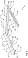
- Fig. 1 shows an alternative installation kit
- fig. 22 shows a shower installation kit 1 according to the invention, including an elongated drain 2 having a longitudinal direction L and two elongated side members 3, 4 each having a longitudinal direction.
- the elongated drain 2 is adapted to be arranged at an inclined shower floor 5 as illustrated in Figs. 16 to 20 and 30 .
- the two elongated side members 3, 4 are adapted to be arranged with their longitudinal directions at right angles to the longitudinal direction of the elongated drain 2, as illustrated in Figs. 1 and 22 , and at opposed sides of the inclined shower floor 5 as illustrated in Figs. 16 to 20 and 30 .
- Each elongated side member 3, 4 has a longitudinal flange 6, 7 adapted to define a slope of the inclined shower floor 5 in relation to a horizontal room floor 8 partially surrounding the inclined shower floor 5, as illustrated in Figs. 16 to 20 and 30 .
- the longitudinal flange 6, 7 of each elongated side member 3, 4 is adapted to be positioned under a floor covering 9 of the inclined shower floor 5.
- the elongated side members 3, 4 may be produced by deep drawing and/or punching of a metal plate, preferably stainless steel. Although two elongated side members 3, 4 are shown in the figures and described below, one of these may be dispensed with, whereby the advantages of the invention may still be obtained. For instance, in Fig 1 , preferably the left elongated side member 3 could be dispensed with, as the right elongated side member 4 in the illustrated embodiment has the further advantage of supporting a partition wall 32, as will be explained below.
- the elongated drain 2 is adapted to be mounted at a distance d from a subfloor structure 10 of the inclined shower floor 5 before installation of the inclined shower floor 5.
- the elongated drain 2 is provided with a front flange 11 adapted to be positioned under the floor covering 9 of the inclined shower floor 5.
- the longitudinal flanges 6, 7 of the side members 3, 4 are connected to and arranged flush with the front flange 11 of the elongated drain 2, as best illustrated in Figs. 1 , 2 , 6 and 22 to 25 .
- the elongated drain 2 is provided with a back flange 12 arranged oppositely to its front flange 11 and adapted to be mounted on a back wall 13, for instance by means of screws 15 and/or glue, as illustrated in Figs. 5 and 6 . Thereby, the elongated drain 2 may be positioned under a vertically extending wall covering 14 of the back wall 13, as illustrated in Figs. 16 and 30 .
- the right side member 4 is provided with a, preferably height adjustable, support member 16 adapted to support the side member 4 against the subfloor structure 10 before installation of the inclined shower floor 5.
- the support member 16 illustrated in these figures is height adjustable by rotation of a ring-formed knob 17 forming a nut and is positioned at the opposite end of the side member 4 in relation to the front flange 11 of the elongated drain 2.
- the skilled person will understand that the height adjustable support member 16 may have any suitable configuration enabling proper height positioning of the side member 4 in relation to the subfloor structure 10.
- the support member 16 may for instance be height adjustable by means of a wedge.
- Fig. 32 illustrates another embodiment of the support member 16 in a height adjustable configuration.
- the support member 16 includes an L-formed bracket 60 having a first flange 61 adapted to be placed flat on the subfloor structure 10 of the inclined shower floor 5 and a second flange 62 adapted to stand up vertically from the subfloor structure 10.
- the first flange 61 is provided with mounting holes 66 for mounting the flange on the floor.
- the second flange 62 is provided with two elongated apertures or slots 63 extending vertically in the mounted position of the L-formed bracket 60.
- the end of the side member 4 may be mounted in a height adjustable manner by means of screws or bolts 64 inserted through the two slots 63, respectively, as illustrated in the figure, in that the bolts 64 may be slit in the longitudinal direction of the slots 63.
- Any suitable number of slots 63 with corresponding bolts 64 could be employed.
- the second flange 62 of the L-formed bracket 60 is provided with two nuts 65 welded onto a side of the flange 62. Corresponding holes have been formed through the second flange 62, so that not shown screws or bolts may be fixed.
- the illustrated L-formed bracket 60 could be mounted in a height adjustable manner on a further, corresponding L-formed bracket that could be mounted on the subfloor 10, instead of the shown L-formed bracket 60.
- two or more such L-formed brackets 60 could be used for extension, if necessary, and a wide degree of height adjustability could be obtained.
- each elongated side member 3, 4 is provided as a separate element having a first end 18 with a first connector 19 adapted for connection to a front edge 20 of the front flange 11 of the elongated drain 2, as best illustrated in Figs. 1 to 4 .
- the connector 19 has the form of an inclined edge face adapted to abut a corresponding inclined edge face of the front flange 11 of the elongated drain 2, wherein said edge faces are inclined to a top surface plane of the front flange 11 of the elongated drain 2 and are provided with holes 21 for connection bolts, screws or similar connection means.
- the elongated side members 3, 4 may be welded or otherwise fixedly connected to the front edge 20 of the front flange 11 of the elongated drain 2.
- Figs. 33 and 34 illustrate a way of detachably connecting an elongated side member 4, provided as a separate element, with the elongated drain 2. It is noted that in Fig. 34 , part of the side member 4 and part of the elongated drain 2 have been let out from the illustration, which is indicated by means of wave-formed lines.
- the elongated side member 4 has a first end 18 with a first connector 19 adapted for connection to a front edge 20 of the front flange 11 of the elongated drain 2.
- the connector 19 includes an inclined edge face 67 adapted to abut a corresponding inclined edge face 68 of the front flange 11 of the elongated drain 2.
- the inclined edge face 68 of the front flange 11 of the elongated drain 2 is formed on an obliquely downwardly bent part 69 of the front flange 11 forming an obtuse angle between the downwardly bent part 69 and the rest of the front flange 11.
- the inclined edge face 67 of the connector 19 may likewise be formed as an obliquely downwardly bent part of the longitudinal flange 7 of the elongated side member 4 forming an acute angle between the obliquely downwardly bent part and the rest of the longitudinal flange 7, but it may just as well have any other suitable form, such as an obliquely cut end face of a U-formed profile (or similar element formed of bent metal plate) extending in the longitudinal direction of and attached to the lower side of the longitudinal flange 7 of the elongated side member 4.
- a U-formed profile may for instance be welded at the free ends of its side flanges (not illustrated in the figure) to the lower side of the longitudinal flange 7.
- the elongated side member 4 is provided with a further connecting flange 70 that may for instance be formed as a bent up part of a bottom flange 72 connecting said side flanges of the above-mentioned U-formed profile attached to the lower side of the longitudinal flange 7.
- the connecting flange 70 may preferably extend in parallel with the inclined edge face 67 of connector 19 and may be provided with suitable pinching means adapted to pinch the inclined edge face 68 of the front flange 11 of the elongated drain 2 against the inclined edge face 67 of connector 19.
- the pinching means has the form of one or more, such as two, screws, preferably un-braco screws 71, inserted into respective threads formed through the connecting flange 70.
- the elongated side member 4 may be detachably fixed to the elongated drain 2.
- the detachable connection of the elongated side member 4 with the elongated drain 2 illustrated in Figs. 33 and 34 may take any suitable form.
- the obliquely downwardly bent part 69 of the front flange 11 of the elongated drain 2 is illustrated as forming an angle of approximately 45 degrees with the front flange 11, but may form any suitable angle, such as 90 degrees.
- the outer edge of the downwardly bent part 69 may also be bent around itself, for instance at an angle of 90 degrees. Thereby, a small channel may be formed under the front flange 11 in which channel tips of screws may conveniently grip and fix the elongated side member 4 to the elongated drain 2.
- the inclined edge face 67 and the connecting flange 70 may be bent at an angle corresponding to the angle of the downwardly bent part 69.
- the separate element of the left elongated side member 3 has a second end 22 with a second connector 19 corresponding to the first connector 19.
- the left elongated side member 3 includes a vertical mounting flange 23 adapted to be mounted flat on a vertical side wall 27 by means of screws 28, nails or the like fastening means, and to be positioned under a vertically extending wall covering 29 of the side wall 27. Because the left elongated side member 3 is provided with a connector 19 at either end, it may be mounted at either side of a shower (inclined shower floor 5), according to requirements, by simply flipping over the member 6 in relation to the elongated drain 2. Thereby, the left elongated side member 3 may easily be mounted at the right side of the shower instead of at the left side as illustrated in the figures.
- the first or second connector 19 may be connected to a corresponding connector of the height adjustable support member 16 illustrated in Figs. 6 , 24 and 25 .
- the longitudinal flange 7 of the right elongated side member 4 has an upwardly open groove 30 extending in the longitudinal direction of the elongated side member 4 and having decreasing depth in the direction towards the elongated drain 2.
- a U-formed rail 31 included by the right elongated side member 4 and having a constant cross-section along its length is inserted into the upwardly open groove 30 so that a lower edge of a partition wall 32 for the shower may be inserted into the U-formed rail 31.
- the U-formed rail 31 and the partition wall 32 may extend horizontally, although the longitudinal flange 7 of the right elongated side member 4 slopes down to the elongated drain 2.
- the U-formed rail 31 extends up to the area of and abuts the back flange 12 of the elongated drain 2, whereby a bottom flange 33 of the U-formed rail 31 extends above a top surface plane 34 of the front flange 11 of the elongated drain 2, as it may be seen in Fig. 11 . Thereby it may be obtained, even with a standard elongated drain 2 not having a groove for the U-formed rail 31, that the partition wall 32 by means of the U-formed rail 31 is supported all the way to the back wall 13 of the shower.
- the elongated side members 3, 4 are integrated with the front flange 11 of the elongated drain 2 in that the first end 18 of each elongated side member 3, 4 is welded to the front flange 11 along welding lines 25.
- the front flange 11 of the elongated drain 2 is provided with a protrusion 24 at either end; the protrusion 24 being welded to the longitudinal flange 6, 7 of the respective elongated side member 3, 4.
- the vertical mounting flange 23 of the left elongated side member 3 extends to the back flange 12 of the elongated drain 2 and is welded thereto along a welding line 26.
- the elongated side members 3, 4 are welded to the elongated drain 2, they may also be soldered or otherwise fixedly connected thereto, or the front flange 11 of the elongated drain 2 and the longitudinal flanges 6, 7 of the elongated side members 3, 4 may be manufactured from one piece of material, such as sheet metal.
- the elongated side members 3, 4 may alternatively be connected to the elongated drain 2 by means of connectors adapted to interconnect by means of connection bolts, screws or similar connection means, just as illustrated above in the embodiment illustrated in Figs. 1 to 21 .
- the right longitudinal flange 7 is provided with an upwardly open groove 30 corresponding to that of the embodiment illustrated in Figs. 1 to 21 and described above.
- the upwardly open groove 30 of the longitudinal flange 7 is defined by two opposed wall members 35, 36, of which a first wall member 35 stops before reaching a line L through a front edge 20 of the front flange 11 of the elongated drain 2 as illustrated in Fig. 23 , and of which a second wall member 36 extends up to the area of and abuts the back flange 12 of the elongated drain 2.
- the second wall member 36 is connected by a bend 37 to a raised longitudinal flange 38 of the right elongated side member 4, whereby the raised longitudinal flange 38 is adapted to be positioned under a floor covering 9 of the horizontal room floor 8, as illustrated in Fig. 30 .
- An end of the second wall member 36 and of the raised longitudinal flange 38 is welded to the back flange 12 of the elongated drain 2 along welding lines 26.
- a U-formed rail 31 included by the right elongated side member 4 and having a constant cross-section along its length is inserted into the upwardly open groove 30 illustrated in Fig. 22 so that a lower edge of a partition wall 32 for the shower may be inserted into the U-formed rail 31.
- the U-formed rail 31 and the partition wall 32 may extend horizontally, although the longitudinal flange 7 of the right elongated side member 4 slopes down to the elongated drain 2.
- the U-formed rail 31 extends up to the area of and abuts the back flange 12 of the elongated drain 2, whereby a bottom flange 33 of the U-formed rail 31 extends above a top surface plane 34 of the front flange 11 of the elongated drain 2. Thereby it may be obtained that the partition wall 32 by means of the U-formed rail 31 is supported all the way to the back wall 13 of the shower.
- the two elongated side members 3, 4 positioned at opposed sides of the inclined shower floor 5 are provided with a connecting, bridge-like, member 39 that is connected detachably to each of said elongated side members 3, 4 at the end of said side members opposed to the end at the front flange 11 of the elongated drain 2.
- the detachable connection is provided by means of hooks 40 at the free ends of the elongated side members 3, 4 adapted to engage with pins or the like of the connecting, bridge-like, member 39.
- the embodiment illustrated in Figs. 1 to 21 may just as well be provided with the connecting, bridge-like, member 39 illustrated in Fig. 25 .
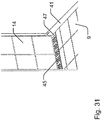
- each elongated side member 3, 4 includes a transition face 41 visible for instance in Figs. 16 , 30 and 31 .
- the transition face 41 is adapted to extend vertically and define a wedge-formed transition between a surface plane of the inclined shower floor 5 and a surface plane of the horizontal room floor 8.
- the left elongated side member 3 provides the transition face 41 in the form of part of the vertical mounting flange 23.
- the right elongated side member 4 provides the transition face 41 in the form of part of a face of the U-formed rail 31 facing the centre of the inclined shower floor 5.
- the U-formed rail 31 may be omitted, whereby the partition wall 32 for the shower may be inserted directly into the upwardly open groove 30 of the right elongated side member 4; in this case, the right elongated side member 4 provides the transition face 41 in the form of part of a face of the partition wall 32, whereby the partition wall 32 is understood to be included by the right elongated side member 4.
- the elongated drain 2 includes a longitudinal drain opening 42 arranged along the front flange 11 of the elongated drain and having a first end 43 and a second end 44.
- the transition face 41 of a respective elongated side member 3, 4 is located at a position less than about 5 centimetres, preferably less than about 3 centimetres, and most preferred less than about 2 centimetres, from the nearest end 43, 44 of the longitudinal drain opening 42 measured in the longitudinal direction of the elongated drain 2.
- a standard grate 45 including a not completely visible surrounding frame associated therewith, mounted over the longitudinal drain opening 42 extends very closely up to or even abuts said wedge-formed transition and thereby visually extends along the full width of the inclined shower floor 5 and possibly extends at least very closely up to an existing wall 27 of a building or a partition wall 32 at the side of the shower floor as illustrated for instance in Figs. 20 and 31 .
- Said not completely visible frame associated with the grate 45 may preferably be a frame that is mounted fixedly on top of the elongated drain 2, so that the grate 45 may be mounted detachably within the frame. Said frame may be dispensed with.
- the transition face 41 of each elongated side member 3, 4 abuts or is positioned nearer than about 7 millimetres, preferably nearer than about 5 millimetres, and most preferred nearer than about 3 millimetres, from a corresponding one of the first and second ends 46, 47 of the elongated grate 45 including the possible surrounding frame associated with the grate.
- the grate 45 visually extends along the full width of the inclined shower floor 5 and possibly extends at least very closely up to an existing wall of a building or a partition wall at the side of the shower floor.
- each elongated side member 3, 4 has an inner edge 48 facing the centre of the inclined shower floor 5, and that said inner edges 48 are positioned between the first and second ends 43, 44 of the longitudinal drain opening 42 measured in the longitudinal direction of the elongated drain 2, as best illustrated in Figs. 2 and 23 .
- a suitably broad longitudinal flange 6, 7 in terms of stability of the connection between the elongated side member 3, 4 and the shower floor 5 may be obtained and at the same time it may be obtained that a standard grate 45, preferably including a surrounding frame associated with the grate 45, mounted over the longitudinal drain opening 42 extends very closely up to or even abuts said wedge-formed transition and thereby visually extends along the full width of the inclined shower floor 5 and possibly extends at least very closely up to an existing wall 27 of a building or a partition wall 32 at the side of the inclined shower floor.
- the longitudinal flange 7 of the right elongated side member 4 has an outer edge 49 facing away from the centre of the inclined shower floor 5 and being arranged in continuation of and flush with a right end edge 50 of the front flange 11 of the elongated drain 2.
- the left elongated side member 3 could have an outer edge 49 facing away from the centre of the inclined shower floor 5 and being arranged in continuation of and flush with a left end edge of the front flange 11 of the elongated drain 2.
- the shower installation kit 1 may include a longitudinal wall flange 51 having a longitudinal direction and being adapted to be arranged with its longitudinal direction vertically and to be positioned under the vertically extending wall covering 14 of a back wall 13.
- the longitudinal wall flange 51 is provided with a U-formed rail 52 mountable along a centre line of the longitudinal wall flange 51 in order to extend through or at least be accessible through the vertically extending wall covering 14 for insertion of an edge of the partition wall 32 for the shower into the U-formed rail 52.
- a lower end of the longitudinal wall flange 51 is provided with an engagement part 53 fitting a corresponding engagement part 54 of the back flange 12 of the elongated drain 2 as illustrated for instance in Figs. 9 and 29 .
- the shower installation kit 1 illustrated in Figs. 1 to 4 may be used for the installation of a shower as illustrated in Figs. 5 to 21 and described in the following.
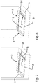
- the elongated drain 2 is fixed to the back wall 13 as illustrated in Fig. 5 .
- the two elongated side members 3, 4 are connected at a first end 18 to the elongated drain 2 as illustrated in Fig. 6 and explained above.
- the left elongated side member 3 is mounted to the vertical side wall 27 so that the longitudinal flange 6 of the left elongated side member 3 slopes correctly down to the elongated drain 2. This may be done by placing a spirit level on top of a pair of appropriately positioned flaps 55 on the left elongated side member 3. It is noted that in case the left elongated side member 3 as illustrated would have to be arranged at the right side of the elongated drain 2, the spirit level would have to be positioned on top of another pair of appropriately positioned flaps 56 on said elongated side member.
- the right elongated side member 4 is supported in relation to the subfloor structure 10 of the inclined shower floor 5 at a second end by means of the height adjustable support member 16.
- the height of said second end is adjusted correctly by rotation of the ring-formed knob 17 so that a bottom of the upwardly open groove 30 is horizontal, which may be done by temporarily inserting the U-formed rail 31 in the upwardly open groove 30 and placing a spirit level on top of it.
- the longitudinal flange 7 of the right elongated side member 4 slopes correctly down to the elongated drain 2.
- the horizontal room floor 8 partially surrounding the shower area where the inclined shower floor 5 is to be installed is grouted, whereby a wedge-formed volume 58 is maintained open so that the horizontal room floor 8 is still spaced in relation to the right elongated side member 4, as illustrated in Fig. 7 .
- the inclined shower floor 5 is grouted to follow the longitudinal flanges 6, 7 of the elongated side members 3, 4, as illustrated in Fig. 8 .
- the longitudinal wall flange 51 has been mounted on the back wall 13 and connected to the elongated drain 2 as explained above.
- reinforcement fabric 57 has been applied to all edges where steel and concrete abut each other.
- Fig. 10 reinforcement fabric 57 has been applied to all edges where steel and concrete abut each other.
- the U-formed rail 31 has been inserted into the upwardly open groove 30.
- the above-mentioned wedge-formed volume 58 has been grouted so that the horizontal room floor 8 extends all up to the U-formed rail 31.
- the longitudinal wall flange 51 has been provided with a longitudinally extending foam packing 59; in Fig. 14 , the grate 45, including a not completely visible surrounding frame associated with the grate, has been mounted over the longitudinal drain opening 42; and in Fig. 15 , the U-formed rail 52 has been mounted on the longitudinal wall flange 51 so that the longitudinally extending foam packing 59 is sandwiched between the longitudinal wall flange 51 and the U-formed rail 52.
- the grate 45 including a not completely visible surrounding frame associated with the grate
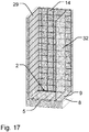
- the inclined shower floor 5 and the horizontal room floor 8 partially surrounding the inclined shower floor 5 has been provided with the floor covering 9, such as tiles
- the back wall 13 has been provided with the vertically extending wall covering 14, such as tiles
- the side wall 27 has been provide with the vertically extending wall covering 29, such as tiles.
- the partition wall 32 has been mounted so that its lower edge is inserted into the U-formed rail 31 extending through the floor covering 9 and its back edge is inserted into the U-formed rail 52 extending through the vertically extending wall covering 14.
- Fig. 18 illustrates an alternative embodiment having a lower U-formed rail 31 not extending up through the floor covering 9
- Fig. 19 illustrates yet another embodiment having a relatively high U-formed rail 31 extending up through the floor covering 9.
- the shower installation kit 1 illustrated in Figs. 22 and 23 may be used for the installation of a shower as illustrated in Figs. 24 to 30 and described in the following.
- the overall installation procedure corresponds to the one described above for the shower installation kit 1 illustrated in Figs. 1 to 4 ; however with some differences as described in the following.
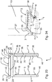
- the elongated drain 2 including the two elongated side members 3, 4 is fixed to the back wall 13 as illustrated in Fig. 24 .
- the left elongated side member 3 is fixed to the vertical side wall 27 whereby it is ensured that the longitudinal flange 6 of the left elongated side member 3 slopes correctly down to the elongated drain 2. This may be done by placing a spirit level on top of a pair of appropriately positioned flaps 55 on the left elongated side member 3.
- the right elongated side member 4 is supported in relation to the subfloor structure 10 of the inclined shower floor 5 at a second end by means of the height adjustable support member 16.
- the height of said second end is adjusted correctly by rotation of the ring-formed knob 17 so that the raised longitudinal flange 38 of the right elongated side member 4 is horizontal, which may be done by placing a spirit level on top of it. Thereby, it may at the same time be obtained that the longitudinal flange 7 of the right elongated side member 4 slopes correctly down to the elongated drain 2.
- the connecting, bridge-like, member 39 has been connected detachably to the hooks 40 at the free end of each of said elongated side members 3, 4 as explained above.
- the horizontal room floor 8 partially surrounding the shower area where the inclined shower floor 5 is to be installed is grouted, as illustrated in Fig. 26 . It is noted that the horizontal room floor 8 has been grouted so that it extends all up to the (horizontal) raised longitudinal flange 38 of the right elongated side member 4. Due to the presence of the horizontal raised longitudinal flange 38, at this stage, it is not necessary, as mentioned by the above-described procedure for installing the shower installation kit 1 illustrated in Figs. 1 to 4 , to maintain a wedge-formed volume open.
- the inclined shower floor 5 is grouted to follow the longitudinal flanges 6, 7 of the elongated side members 3, 4, as illustrated in Fig. 27 .
- the longitudinal wall flange 51 has been mounted on the back wall 13 and connected to the elongated drain 2 as explained above.
- reinforcement fabric 57 has been applied to all edges where steel and concrete abut each other.
- the longitudinal wall flange 51 has been provided with the longitudinally extending foam packing 59 (not visible); the grate 45 including a surrounding frame associated with the grate has been mounted over the longitudinal drain opening 42; and the U-formed rail 52 has been mounted on the longitudinal wall flange 51 so that the longitudinally extending foam packing 59 is sandwiched between the longitudinal wall flange 51 and the U-formed rail 52.
- the inclined shower floor 5 and the horizontal room floor 8 partially surrounding the inclined shower floor 5 has been provided with the floor covering 9, such as tiles
- the back wall 13 has been provided with the vertically extending wall covering 14, such as tiles
- the side wall 27 has been provide with the vertically extending wall covering 29, such as tiles.
- the partition wall 32 has been mounted in the same way as illustrated in Fig. 17 and explained above.
- the two alternatives illustrated in Figs. 18 and 19 having a, respectively, low and high U-formed rail 31, are also possible for this embodiment.
Landscapes
- Health & Medical Sciences (AREA)
- Public Health (AREA)
- Epidemiology (AREA)
- General Health & Medical Sciences (AREA)
- Life Sciences & Earth Sciences (AREA)
- Engineering & Computer Science (AREA)
- Hydrology & Water Resources (AREA)
- Water Supply & Treatment (AREA)
- Bathtubs, Showers, And Their Attachments (AREA)
- Residential Or Office Buildings (AREA)
- Sink And Installation For Waste Water (AREA)
Claims (19)
- Kit d'installation de douche (1) incluant une canalisation d'évacuation allongée (2) présentant une direction longitudinale et étant adaptée pour être agencée au niveau d'un sol de douche incliné (5), la canalisation d'évacuation allongée (2) étant adaptée pour être montée à une distance (d) d'une structure de sous-plancher (10) du sol de douche incliné (5) avant l'installation du sol de douche incliné, et la canalisation d'évacuation allongée (2) étant pourvue d'une bride avant (11) adaptée pour être positionnée sous un revêtement de sol (9) du sol de douche incliné (5), caractérisé en ce que le kit d'installation de douche (1) inclut au moins un élément latéral allongé (3, 4) présentant une direction longitudinale et étant adapté pour être agencé avec sa direction longitudinale à angles droits par rapport à la direction longitudinale de la canalisation d'évacuation allongée (2) et d'un côté du sol de douche incliné (5), en ce que l'au moins un élément latéral allongé (3, 4) présente une bride longitudinale (6, 7) adaptée pour définir une pente du sol de douche incliné (5) par rapport à un sol de pièce horizontal (8) entourant au moins partiellement le sol de douche incliné (5), où la bride longitudinale (7) est en pente vers la canalisation d'évacuation allongée (2) lorsque le kit d'installation est positionné sur la structure de sous-plancher (10), en ce que la bride longitudinale (6, 7) de l'au moins un élément latéral allongé (3, 4) est adaptée pour être positionnée sous le revêtement de sol (9) du sol de douche incliné (5), et en ce que la bride longitudinale (6, 7) de l'au moins un élément latéral allongé (3, 4) est raccordée à et agencée dans l'alignement de la bride avant (11) de la canalisation d'évacuation allongée (2), en ce que l'au moins un élément latéral allongé (3, 4) comprend en outre une bride longitudinale surélevée (38), qui est adaptée pour être horizontale et adaptée pour être positionnée sous un revêtement de sol (9) d'un sol de pièce horizontal lorsque le kit d'installation (1) est positionné sur la structure de sous-plancher (10).
- Kit d'installation de douche selon la revendication 1, dans lequel la canalisation d'évacuation allongée (2) présente deux éléments latéraux allongés (3, 4) adaptés pour être agencés à des côtés opposés du sol de douche incliné (5).
- Kit d'installation de douche selon la revendication 1 ou 2, dans lequel au moins un de l'au moins un élément latéral (3, 4) est pourvu d'un élément de support (16) de préférence réglable en hauteur adapté pour supporter ledit élément latéral (4) contre une structure de sous-plancher (10) avant l'installation du sol de douche incliné (5), l'élément de support (16) étant positionné à une distance de la bride avant (11) de la canalisation d'évacuation allongée (2) et de préférence à l'extrémité opposée dudit élément latéral (4) par rapport à la bride avant (11) de la canalisation d'évacuation allongée (2).
- Kit d'installation de douche selon l'une quelconque des revendications 1 à 3, dans lequel chaque élément latéral allongé (3, 4) est fourni comme élément séparé présentant une première extrémité (18) avec un premier connecteur (19) adapté pour le raccordement à un bord avant (20) de la bride avant (11) de la canalisation d'évacuation allongée (2), et, de préférence, dans lequel le connecteur (19) présente la forme d'une face de bord inclinée adaptée pour venir en butée avec une face de bord inclinée correspondante de la bride avant (11) de la canalisation d'évacuation allongée (2), lesdites faces de bord étant inclinées sur un plan de surface supérieur de la bride avant (11) de la canalisation d'évacuation allongée (2) et étant pourvues de trous (21) pour des boulons, des vis de raccordement ou des moyens de raccordement similaires.
- Kit d'installation de douche selon la revendication 4, dans lequel l'élément séparé d'au moins un de l'au moins un élément latéral allongé (3, 4) présente une seconde extrémité (22) avec un second connecteur (19) correspondant au premier connecteur (19), et, de préférence, dans lequel le second connecteur (19) est raccordé à un connecteur correspondant d'un élément de support (16) de préférence réglable en hauteur adapté pour supporter ledit élément latéral (4) contre une structure de sous-plancher (10) avant l'installation du sol de douche incliné (5).
- Kit d'installation de douche selon l'une quelconque des revendications 1 à 3, dans lequel au moins un de l'au moins un élément latéral allongé (3, 4) s'intègre à la bride avant (11) de la canalisation d'évacuation allongée (2) en étant soudé, brasé ou autrement raccordé de manière fixe à celle-ci ou en étant fabriqué d'une pièce de matériau, comme une tôle.
- Kit d'installation de douche selon l'une quelconque des revendications précédentes, dans lequel deux éléments latéraux allongés (3, 4) positionnés à des côtés opposés du sol de douche incliné (5) sont pourvus d'un élément de raccordement en forme de pont (39) raccordé, de préférence de manière détachable, à chacun desdits éléments latéraux allongés (3, 4) à l'extrémité (22) desdits éléments latéraux opposée à l'extrémité (19) au niveau de la bride avant (11) de la canalisation d'évacuation allongée (2).
- Kit d'installation de douche selon l'une quelconque des revendications précédentes, dans lequel au moins un de l'au moins un élément latéral allongé (3, 4) inclut une bride de montage verticale (23) adaptée pour être montée à plat sur une paroi latérale verticale (27), de préférence au moyen de vis (28), de clous ou de moyens d'attache semblables, et pour être positionnée sous un revêtement de paroi s'étendant verticalement (29) de la paroi latérale (27).
- Kit d'installation de douche selon l'une quelconque des revendications précédentes, dans lequel chaque élément latéral allongé (3, 4) inclut une face de transition (41) adaptée pour s'étendre verticalement et définir une transition en forme de coin entre un plan de surface du sol de douche incliné (5) et un plan de surface du sol de pièce horizontal (8), dans lequel la canalisation d'évacuation allongée (2) inclut une ouverture de canalisation d'évacuation longitudinale (42) agencée le long de la bride avant (11) de la canalisation d'évacuation allongée (2) et présentant une première extrémité (43) et une seconde extrémité (44), et, de préférence, dans lequel la face de transition (41) d'un élément latéral allongé respectif (3, 4) est située au niveau d'une position inférieure à environ 5 centimètres, de préférence inférieure à environ 3 centimètres, et le plus préférentiellement inférieure à environ 2 centimètres, depuis l'extrémité la plus proche (43, 44) de l'ouverture de canalisation d'évacuation longitudinale (42) mesurée dans la direction longitudinale de la canalisation d'évacuation allongée (2).
- Kit d'installation de douche selon la revendication 9, dans lequel l'ouverture de canalisation d'évacuation longitudinale (42) est pourvue d'une grille allongée correspondante (45), de préférence incluant un cadre d'encadrement associé à la grille, présentant une première extrémité (46) et une seconde extrémité (47), et dans lequel la face de transition (41) de chaque élément latéral allongé (3, 4) vient en butée avec ou est positionnée plus proche qu'environ 7 millimètres, de préférence plus proche qu'environ 5 millimètres, et le plus préférentiellement plus proche qu'environ 3 millimètres, d'une correspondante des première et seconde extrémités (46, 47) de la grille allongée (45) incluant un quelconque cadre d'encadrement associé à la grille.
- Kit d'installation de douche selon la revendication 9 ou 10, dans lequel la bride longitudinale (6, 7) de chaque élément latéral allongé (3, 4) présente un bord intérieur (48) faisant face au centre du sol de douche incliné (5), dans lequel lesdits bords intérieurs (48) sont positionnés entre les première et seconde extrémités (43, 44) de l'ouverture de canalisation d'évacuation longitudinale (42) mesurée dans la direction longitudinale de la canalisation d'évacuation allongée (2), et, de préférence, dans lequel la bride longitudinale (7) d'au moins un (4) des éléments latéraux allongés (3, 4) présente un bord extérieur (49) orienté à l'opposé du centre du sol de douche incliné (5) et étant agencé en continuation ou dans l'alignement d'un bord d'extrémité (50) de la bride avant (11) de la canalisation d'évacuation allongée (2).
- Kit d'installation de douche selon l'une quelconque des revendications précédentes, dans lequel la bride longitudinale (7) d'au moins un (4) des éléments latéraux allongés (3, 4) présente une rainure ouverture vers le haut (30) s'étendant dans la direction longitudinale de l'élément latéral allongé (4) et présentant une profondeur décroissante dans la direction vers la canalisation d'évacuation allongée (2), et dans lequel, de préférence, un rail en forme de U (31) présentant une section transversale constante le long de sa longueur est inséré dans la rainure ouverte vers le haut (30) de sorte qu'un bord inférieur d'une paroi de séparation (32) pour la douche puisse être inséré dans le rail en forme de U (31).
- Kit d'installation de douche selon la revendication 12, dans lequel la canalisation d'évacuation allongée (2) est pourvue d'une bride arrière (12) agencée de manière opposée à sa bride avant (11) et adaptée pour être positionnée sous un revêtement de paroi s'étendant verticalement (14), dans lequel le rail en forme de U (31) s'étend jusqu'à la zone de ou vient en butée avec la bride arrière (12) de la canalisation d'évacuation allongée (2), et, de préférence, dans lequel une bride inférieure (33) du rail en forme de U (31) s'étend au-dessus d'un plan de surface supérieur (34) de la bride avant (11) de la canalisation d'évacuation allongée (2).
- Kit d'installation de douche selon la revendication 13, dans lequel la rainure ouverte vers le haut (30) de la bride longitudinale (7) d'au moins un (4) des éléments latéraux allongés (3, 4) est définie par deux éléments de paroi opposés (35, 36), dont un premier élément de paroi (35) s'arrête avant d'atteindre une ligne (L) à travers un bord avant (20) de la bride avant (11) de la canalisation d'évacuation allongée (2), et dont un second élément de paroi (36) s'étend jusqu'à la zone de ou vient en butée avec la bride arrière (12) de la canalisation d'évacuation allongée (2), et, de préférence, dans lequel le second élément de paroi (36) est raccordé par un coude (37) à une bride longitudinale surélevée (38) de l'élément latéral allongé respectif (4), ladite bride longitudinale surélevée (38) étant adaptée pour être positionnée sous un revêtement de sol (9) du sol de pièce horizontal (8).
- Kit d'installation de douche selon l'une quelconque des revendications précédentes, dans lequel le kit (1) inclut une bride de paroi longitudinale (51) présentant une direction longitudinale et adaptée pour être agencée avec sa direction longitudinale verticalement et pour être positionnée sous un revêtement de paroi s'étendant verticalement (14) d'une paroi arrière (13), dans lequel la bride de paroi longitudinale (51) est pourvue d'un rail en forme de U (52) pouvant être monté le long d'une ligne centrale de la bride de paroi longitudinale (51) afin de s'étendre à travers ou au moins être accessible à travers le revêtement de paroi s'étendant verticalement (14) pour l'insertion d'un bord d'une paroi de séparation (32) pour la douche dans le rail en forme de U (52), et, de préférence, dans lequel une extrémité inférieure de la bride de paroi longitudinale (51) est pourvue d'une partie de mise en prise (53) s'ajustant dans une partie de mise en prise correspondante (54) d'une bride arrière (12) de la canalisation d'évacuation allongée (2).
- Douche incluant un kit d'installation de douche selon l'une quelconque des revendications précédentes, dans laquelle, avant l'installation du sol de douche incliné (5), la canalisation d'évacuation allongée (2) a été fixée à une paroi (13) et chacun des deux éléments latéraux allongés (3, 4) a été raccordé au niveau d'une première (18) de ses extrémités à la canalisation d'évacuation allongée (2) et est soit monté sur une paroi, soit supporté par rapport à une structure de sous-plancher (10) du sol de douche incliné (5) au niveau d'une seconde de ses extrémités, et dans laquelle, ultérieurement au montage de la canalisation d'évacuation allongée (2) et des deux éléments latéraux allongés (3, 4), le sol de douche incliné (5) a d'abord été jointoyé pour suivre les brides longitudinales (6, 7) des éléments latéraux allongés (3, 4) et a ensuite été pourvu d'un revêtement de sol (9), comme des carreaux.
- Procédé d'installation d'une douche, selon lequel une canalisation d'évacuation allongée (2) présentant une direction longitudinale est agencée au niveau d'un sol de douche incliné (5), selon lequel la canalisation d'évacuation allongée (2) est montée à une distance d'une structure de sous-plancher (10) du sol de douche incliné (5) avant l'installation du sol de douche incliné, et selon lequel la canalisation d'évacuation allongée (2) est pourvue d'une bride avant (11) qui est positionnée sous un revêtement de sol (9) du sol de douche incliné (5), caractérisé en ce qu'au moins un élément latéral allongé (3, 4) présentant une direction longitudinale est agencé avec sa direction longitudinale à angles droits par rapport à la direction longitudinale de la canalisation d'évacuation allongée (2) et d'un côté du sol de douche incliné (5), en ce que l'au moins un élément latéral allongé (3, 4) présente une bride longitudinale (6, 7) définissant une pente du sol de douche incliné (5) par rapport à un sol de pièce horizontal (8) entourant au moins partiellement le sol de douche incliné (5) où la bride longitudinale (7) est en pente vers la canalisation d'évacuation allongée (2), en ce que la bride longitudinale (6, 7) de l'au moins un élément latéral allongé (3, 4) est positionnée sous le revêtement de sol (9) du sol de douche incliné (5), et en ce que la bride longitudinale (6, 7) de l'au moins un élément latéral (3, 4) est raccordée à et agencée dans l'alignement de la bride avant (11) de la canalisation d'évacuation allongée (2) avant l'installation du sol de douche incliné (5), en ce que l'au moins un élément latéral fournit une bride longitudinale surélevée (38), qui est adaptée pour être horizontale et adaptée pour être positionnée sous un revêtement de sol (9) d'un sol de pièce horizontal lorsque le kit d'installation est positionné sur la structure de sous-plancher (10).
- Procédé d'installation d'une douche selon la revendication 17 au moyen d'un kit d'installation de douche (1) selon l'une quelconque des revendications 1 à 15.
- Procédé d'installation d'une douche selon la revendication 17 ou 18, selon lequel, avant l'installation du sol de douche incliné (5), la canalisation d'évacuation allongée (2) est fixée à une paroi (13) et chacun de l'au moins un élément latéral allongé (3, 4) est raccordé au niveau d'une première (18) de ses extrémités à la canalisation d'évacuation allongée (2) et est soit monté sur une paroi (27), soit supporté par rapport à une structure de sous-plancher (10) du sol de douche incliné (5) au niveau d'une seconde de ses extrémités, et selon lequel, ultérieurement au montage de la canalisation d'évacuation allongée (2) et de l'au moins un élément latéral allongé (3, 4), le sol de douche incliné (5) est d'abord jointoyé pour suivre la bride longitudinale (6, 7) de l'au moins un élément latéral allongé (3, 4) et est ensuite pourvu d'un revêtement de sol (9), comme des carreaux.
Applications Claiming Priority (2)
| Application Number | Priority Date | Filing Date | Title |
|---|---|---|---|
| DKPA201270820A DK177596B1 (en) | 2012-12-21 | 2012-12-21 | Shower installation kit and method of installing shower |
| PCT/EP2013/076907 WO2014095868A1 (fr) | 2012-12-21 | 2013-12-17 | Kit d'installation de douche et procédé d'installation de douche |
Publications (2)
| Publication Number | Publication Date |
|---|---|
| EP2935710A1 EP2935710A1 (fr) | 2015-10-28 |
| EP2935710B1 true EP2935710B1 (fr) | 2020-01-22 |
Family
ID=49546735
Family Applications (1)
| Application Number | Title | Priority Date | Filing Date |
|---|---|---|---|
| EP13811450.9A Active EP2935710B1 (fr) | 2012-12-21 | 2013-12-17 | Kit d'installation de douche et procédé d'installation de douche |
Country Status (6)
| Country | Link |
|---|---|
| US (1) | US10765267B2 (fr) |
| EP (1) | EP2935710B1 (fr) |
| CN (1) | CN105008629B (fr) |
| CA (1) | CA2895861C (fr) |
| DK (1) | DK177596B1 (fr) |
| WO (1) | WO2014095868A1 (fr) |
Cited By (1)
| Publication number | Priority date | Publication date | Assignee | Title |
|---|---|---|---|---|
| US11317767B2 (en) | 2019-01-22 | 2022-05-03 | Johns Manville | Field fabricated shower system |
Families Citing this family (8)
| Publication number | Priority date | Publication date | Assignee | Title |
|---|---|---|---|---|
| EP3662800B1 (fr) * | 2017-08-03 | 2023-09-06 | Nietos De Miguel Martinez Ramirez, S.L. | Bac de douche |
| USD941967S1 (en) * | 2019-11-13 | 2022-01-25 | Everhard Industries Pty Ltd | Drain grate |
| USD941968S1 (en) * | 2019-11-13 | 2022-01-25 | Everhard Industries Pty Ltd | Drain grate |
| USD941966S1 (en) * | 2019-11-13 | 2022-01-25 | Everhard Industries Pty Ltd | Drain grate |
| USD942594S1 (en) * | 2019-11-13 | 2022-02-01 | Everhard Industries Pty Ltd | Drain grate |
| CN110777918A (zh) * | 2019-12-04 | 2020-02-11 | 李军成 | 线性地漏 |
| US12534899B2 (en) * | 2022-12-09 | 2026-01-27 | Midwest Design Group | Trench drains with suspended grates |
| US12546102B2 (en) * | 2023-02-23 | 2026-02-10 | Advanced Drainage Systems, Inc. | Linear or trench drain systems |
Citations (1)
| Publication number | Priority date | Publication date | Assignee | Title |
|---|---|---|---|---|
| CH701285B1 (de) * | 2007-10-31 | 2010-12-31 | Schaco Handel Ag | Montagevorrichtung für Dusche und Dusche mit einer solchen Montagevorrichtung. |
Family Cites Families (23)
| Publication number | Priority date | Publication date | Assignee | Title |
|---|---|---|---|---|
| US5493738A (en) | 1992-11-06 | 1996-02-27 | Gordon Sanderson | Water guiding strip for use in association with a shower stall or bathtub |
| DE19849264A1 (de) | 1998-10-26 | 2000-05-04 | A & S Baeder Gmbh & Co | Dusch- oder Badewannenabtrennung |
| IT1311663B1 (it) * | 1999-11-18 | 2002-03-14 | Calibe S R L | Struttura di attrezzatura per effettuare la doccia. |
| CN1181247C (zh) | 2000-03-24 | 2004-12-22 | 乌尼德雷恩有限公司 | 排水装置和具有排水装置的建筑结构 |
| DE10061183B4 (de) | 2000-12-07 | 2010-05-20 | A & S Bäder GmbH & Co. | Dusch- oder Badewannenabtrennung |
| ITMI20031724A1 (it) * | 2003-09-08 | 2005-03-09 | Megius S P A | Struttura di piatto e di cabina modulare per doccia. |
| DE202004008885U1 (de) | 2004-06-04 | 2005-10-13 | Hüppe GmbH & Co. | Integrierte Verbindungselemente |
| DE202005021587U1 (de) | 2005-12-19 | 2008-10-09 | A & S Bäder GmbH & Co. | Unterputzschiene für eine Glasscheibe o.dgl., sowie eine Duschabtrennung mit einer solchen Unterputzschiene |
| DE102005061133B3 (de) | 2005-12-19 | 2007-05-24 | A & S Bäder GmbH & Co. | Montagevorrichtung für eine Duschabtrennung und Verfahren zur Verwendung einer derartigen Montagevorrichtung |
| DE102006000893A1 (de) | 2006-01-04 | 2007-07-05 | A & S Bäder GmbH & Co. | Ausgleichsprofil |
| DE202006019995U1 (de) | 2006-01-04 | 2007-07-26 | A & S Bäder GmbH & Co. | Ausgleichsprofil |
| DE202007015355U1 (de) * | 2007-11-02 | 2008-03-27 | Schaco Handel Ag | Montagevorrichtung für Dusche und Dusche mit einer solchen Montagevorrichtung |
| DE202008003009U1 (de) * | 2008-02-01 | 2009-03-19 | Illbruck Sanitärtechnik GmbH | Duschbodenelement |
| DE202008003050U1 (de) * | 2008-03-04 | 2008-07-03 | Mepa - Pauli Und Menden Gmbh | Duschrinnenanordnung |
| US8239974B2 (en) * | 2008-12-29 | 2012-08-14 | Josef Erlebach | Elongated shower drain |
| CN101773373A (zh) * | 2009-01-09 | 2010-07-14 | 穆瑞·古修 | 淋浴底座系统及其安装方法 |
| FR2945413B1 (fr) * | 2009-05-15 | 2011-05-06 | Aplix Sa | Element d'accrochage pour former la partie male d'un auto-agrippant |
| US20110047695A1 (en) | 2009-08-26 | 2011-03-03 | James Daniel Niedens | Drain assembly |
| DE202010001352U1 (de) | 2010-01-25 | 2011-06-09 | Schlüter-Systems KG, 58640 | Zierleiste für Duschen |
| US8505131B2 (en) * | 2010-07-27 | 2013-08-13 | Perimedrain Systems, LLC | Trench drain system and method of installation on level floor surface, paticulary for shower rooms |
| CN201809827U (zh) * | 2010-09-17 | 2011-04-27 | Sfa中国有限公司 | 一种淋浴用的排水装置 |
| DE202011051047U1 (de) * | 2011-08-19 | 2012-11-28 | Mepa-Pauli Und Menden Gmbh | Ablaufanordnung |
| DE102011119697A1 (de) * | 2011-11-29 | 2013-05-29 | Dieter Preissing | Duschsystem |
-
2012
- 2012-12-21 DK DKPA201270820A patent/DK177596B1/en active
-
2013
- 2013-12-17 EP EP13811450.9A patent/EP2935710B1/fr active Active
- 2013-12-17 CA CA2895861A patent/CA2895861C/fr active Active
- 2013-12-17 US US14/654,386 patent/US10765267B2/en active Active
- 2013-12-17 WO PCT/EP2013/076907 patent/WO2014095868A1/fr not_active Ceased
- 2013-12-17 CN CN201380073555.2A patent/CN105008629B/zh active Active
Patent Citations (1)
| Publication number | Priority date | Publication date | Assignee | Title |
|---|---|---|---|---|
| CH701285B1 (de) * | 2007-10-31 | 2010-12-31 | Schaco Handel Ag | Montagevorrichtung für Dusche und Dusche mit einer solchen Montagevorrichtung. |
Cited By (2)
| Publication number | Priority date | Publication date | Assignee | Title |
|---|---|---|---|---|
| US11317767B2 (en) | 2019-01-22 | 2022-05-03 | Johns Manville | Field fabricated shower system |
| US11607086B2 (en) | 2019-01-22 | 2023-03-21 | Johns Manville | Field fabricated shower system |
Also Published As
| Publication number | Publication date |
|---|---|
| WO2014095868A1 (fr) | 2014-06-26 |
| DK177596B1 (en) | 2013-11-11 |
| CN105008629B (zh) | 2017-08-04 |
| US20150342420A1 (en) | 2015-12-03 |
| US10765267B2 (en) | 2020-09-08 |
| CN105008629A (zh) | 2015-10-28 |
| EP2935710A1 (fr) | 2015-10-28 |
| CA2895861C (fr) | 2021-06-08 |
| CA2895861A1 (fr) | 2014-06-26 |
Similar Documents
| Publication | Publication Date | Title |
|---|---|---|
| EP2935710B1 (fr) | Kit d'installation de douche et procédé d'installation de douche | |
| CA2788273C (fr) | Avaloir de sol | |
| US8640390B2 (en) | Decorative strip for showers | |
| US8850633B2 (en) | Elongated shower drain and shower door assembly | |
| US8239974B2 (en) | Elongated shower drain | |
| CA2995216C (fr) | Evacuation de douche montee sur paroi | |
| AU2018229509B2 (en) | Shower hob apparatus | |
| US20120079652A1 (en) | Reversible low profile shower base | |
| AU2012307532A1 (en) | Drain for a floor-level shower | |
| EP2466023A1 (fr) | Sortie d'écoulement en forme de panneau plat | |
| GB2476028A (en) | Plinth for ATM and similar apparatus | |
| US20110132470A1 (en) | Floor drain for a sanitary installation and method for installing such a floor drain | |
| EP0877843B1 (fr) | Revetement interieur pour la refection de pieces, en particulier de salles de bains, ainsi qu'un procede pour restaurer ces pieces | |
| EP4202136A1 (fr) | Ensemble drain de douche et kit pour son installation | |
| HUP0202454A2 (en) | Method for installing a tub support and tub shell mounted in a tub support | |
| EP3431674A1 (fr) | Dispositif d'installation pour une structure de montage d'un appareil sanitair et son utilisation dans un method d'installation dudite structure de montage | |
| US8061093B2 (en) | Window frame with installation hooks | |
| WO2010089590A1 (fr) | Ensemble cadre de porte et procédé d'installation de portes | |
| KR200415831Y1 (ko) | 칸막이용 경량 패널의 높낮이 조절장치 | |
| CN112663903B (zh) | 一种地暖基板安装墙挂角钢结构 | |
| DE3142938A1 (de) | Gehaeuse zur aufnahme haustechnischer installationen | |
| RU53325U1 (ru) | Направляющий профиль каркаса | |
| EP1629755A2 (fr) | Installation de douche | |
| AU2006207846B2 (en) | Wall cladding | |
| JP2010275817A (ja) | 建物ユニットのトイレ構造及び施工方法 |
Legal Events
| Date | Code | Title | Description |
|---|---|---|---|
| PUAI | Public reference made under article 153(3) epc to a published international application that has entered the european phase |
Free format text: ORIGINAL CODE: 0009012 |
|
| 17P | Request for examination filed |
Effective date: 20150717 |
|
| AK | Designated contracting states |
Kind code of ref document: A1 Designated state(s): AL AT BE BG CH CY CZ DE DK EE ES FI FR GB GR HR HU IE IS IT LI LT LU LV MC MK MT NL NO PL PT RO RS SE SI SK SM TR |
|
| AX | Request for extension of the european patent |
Extension state: BA ME |
|
| DAX | Request for extension of the european patent (deleted) | ||
| 17Q | First examination report despatched |
Effective date: 20161010 |
|
| STAA | Information on the status of an ep patent application or granted ep patent |
Free format text: STATUS: EXAMINATION IS IN PROGRESS |
|
| GRAP | Despatch of communication of intention to grant a patent |
Free format text: ORIGINAL CODE: EPIDOSNIGR1 |
|
| STAA | Information on the status of an ep patent application or granted ep patent |
Free format text: STATUS: GRANT OF PATENT IS INTENDED |
|
| INTG | Intention to grant announced |
Effective date: 20190809 |
|
| GRAS | Grant fee paid |
Free format text: ORIGINAL CODE: EPIDOSNIGR3 |
|
| GRAA | (expected) grant |
Free format text: ORIGINAL CODE: 0009210 |
|
| STAA | Information on the status of an ep patent application or granted ep patent |
Free format text: STATUS: THE PATENT HAS BEEN GRANTED |
|
| RIN1 | Information on inventor provided before grant (corrected) |
Inventor name: HONORE, JACOB Inventor name: SECHER, PETER |
|
| AK | Designated contracting states |
Kind code of ref document: B1 Designated state(s): AL AT BE BG CH CY CZ DE DK EE ES FI FR GB GR HR HU IE IS IT LI LT LU LV MC MK MT NL NO PL PT RO RS SE SI SK SM TR |
|
| REG | Reference to a national code |
Ref country code: GB Ref legal event code: FG4D |
|
| REG | Reference to a national code |
Ref country code: CH Ref legal event code: EP |
|
| REG | Reference to a national code |
Ref country code: DE Ref legal event code: R096 Ref document number: 602013065334 Country of ref document: DE |
|
| REG | Reference to a national code |
Ref country code: AT Ref legal event code: REF Ref document number: 1226982 Country of ref document: AT Kind code of ref document: T Effective date: 20200215 |
|
| REG | Reference to a national code |
Ref country code: IE Ref legal event code: FG4D |
|
| REG | Reference to a national code |
Ref country code: FI Ref legal event code: FGE |
|
| REG | Reference to a national code |
Ref country code: NL Ref legal event code: FP |
|
| REG | Reference to a national code |
Ref country code: NO Ref legal event code: T2 Effective date: 20200122 |
|
| REG | Reference to a national code |
Ref country code: SE Ref legal event code: TRGR |
|
| REG | Reference to a national code |
Ref country code: LT Ref legal event code: MG4D |
|
| PG25 | Lapsed in a contracting state [announced via postgrant information from national office to epo] |
Ref country code: PT Free format text: LAPSE BECAUSE OF FAILURE TO SUBMIT A TRANSLATION OF THE DESCRIPTION OR TO PAY THE FEE WITHIN THE PRESCRIBED TIME-LIMIT Effective date: 20200614 Ref country code: RS Free format text: LAPSE BECAUSE OF FAILURE TO SUBMIT A TRANSLATION OF THE DESCRIPTION OR TO PAY THE FEE WITHIN THE PRESCRIBED TIME-LIMIT Effective date: 20200122 |
|
| PG25 | Lapsed in a contracting state [announced via postgrant information from national office to epo] |
Ref country code: LV Free format text: LAPSE BECAUSE OF FAILURE TO SUBMIT A TRANSLATION OF THE DESCRIPTION OR TO PAY THE FEE WITHIN THE PRESCRIBED TIME-LIMIT Effective date: 20200122 Ref country code: GR Free format text: LAPSE BECAUSE OF FAILURE TO SUBMIT A TRANSLATION OF THE DESCRIPTION OR TO PAY THE FEE WITHIN THE PRESCRIBED TIME-LIMIT Effective date: 20200423 Ref country code: BG Free format text: LAPSE BECAUSE OF FAILURE TO SUBMIT A TRANSLATION OF THE DESCRIPTION OR TO PAY THE FEE WITHIN THE PRESCRIBED TIME-LIMIT Effective date: 20200422 Ref country code: HR Free format text: LAPSE BECAUSE OF FAILURE TO SUBMIT A TRANSLATION OF THE DESCRIPTION OR TO PAY THE FEE WITHIN THE PRESCRIBED TIME-LIMIT Effective date: 20200122 |
|
| REG | Reference to a national code |
Ref country code: DE Ref legal event code: R097 Ref document number: 602013065334 Country of ref document: DE |
|
| PG25 | Lapsed in a contracting state [announced via postgrant information from national office to epo] |
Ref country code: LT Free format text: LAPSE BECAUSE OF FAILURE TO SUBMIT A TRANSLATION OF THE DESCRIPTION OR TO PAY THE FEE WITHIN THE PRESCRIBED TIME-LIMIT Effective date: 20200122 Ref country code: ES Free format text: LAPSE BECAUSE OF FAILURE TO SUBMIT A TRANSLATION OF THE DESCRIPTION OR TO PAY THE FEE WITHIN THE PRESCRIBED TIME-LIMIT Effective date: 20200122 Ref country code: DK Free format text: LAPSE BECAUSE OF FAILURE TO SUBMIT A TRANSLATION OF THE DESCRIPTION OR TO PAY THE FEE WITHIN THE PRESCRIBED TIME-LIMIT Effective date: 20200122 Ref country code: SM Free format text: LAPSE BECAUSE OF FAILURE TO SUBMIT A TRANSLATION OF THE DESCRIPTION OR TO PAY THE FEE WITHIN THE PRESCRIBED TIME-LIMIT Effective date: 20200122 Ref country code: EE Free format text: LAPSE BECAUSE OF FAILURE TO SUBMIT A TRANSLATION OF THE DESCRIPTION OR TO PAY THE FEE WITHIN THE PRESCRIBED TIME-LIMIT Effective date: 20200122 Ref country code: CZ Free format text: LAPSE BECAUSE OF FAILURE TO SUBMIT A TRANSLATION OF THE DESCRIPTION OR TO PAY THE FEE WITHIN THE PRESCRIBED TIME-LIMIT Effective date: 20200122 Ref country code: SK Free format text: LAPSE BECAUSE OF FAILURE TO SUBMIT A TRANSLATION OF THE DESCRIPTION OR TO PAY THE FEE WITHIN THE PRESCRIBED TIME-LIMIT Effective date: 20200122 Ref country code: RO Free format text: LAPSE BECAUSE OF FAILURE TO SUBMIT A TRANSLATION OF THE DESCRIPTION OR TO PAY THE FEE WITHIN THE PRESCRIBED TIME-LIMIT Effective date: 20200122 |
|
| PLBE | No opposition filed within time limit |
Free format text: ORIGINAL CODE: 0009261 |
|
| STAA | Information on the status of an ep patent application or granted ep patent |
Free format text: STATUS: NO OPPOSITION FILED WITHIN TIME LIMIT |
|
| 26N | No opposition filed |
Effective date: 20201023 |
|
| PG25 | Lapsed in a contracting state [announced via postgrant information from national office to epo] |
Ref country code: IT Free format text: LAPSE BECAUSE OF FAILURE TO SUBMIT A TRANSLATION OF THE DESCRIPTION OR TO PAY THE FEE WITHIN THE PRESCRIBED TIME-LIMIT Effective date: 20200122 |
|
| PG25 | Lapsed in a contracting state [announced via postgrant information from national office to epo] |
Ref country code: SI Free format text: LAPSE BECAUSE OF FAILURE TO SUBMIT A TRANSLATION OF THE DESCRIPTION OR TO PAY THE FEE WITHIN THE PRESCRIBED TIME-LIMIT Effective date: 20200122 Ref country code: PL Free format text: LAPSE BECAUSE OF FAILURE TO SUBMIT A TRANSLATION OF THE DESCRIPTION OR TO PAY THE FEE WITHIN THE PRESCRIBED TIME-LIMIT Effective date: 20200122 |
|
| PG25 | Lapsed in a contracting state [announced via postgrant information from national office to epo] |
Ref country code: MC Free format text: LAPSE BECAUSE OF FAILURE TO SUBMIT A TRANSLATION OF THE DESCRIPTION OR TO PAY THE FEE WITHIN THE PRESCRIBED TIME-LIMIT Effective date: 20200122 |
|
| REG | Reference to a national code |
Ref country code: BE Ref legal event code: MM Effective date: 20201231 |
|
| PG25 | Lapsed in a contracting state [announced via postgrant information from national office to epo] |
Ref country code: IE Free format text: LAPSE BECAUSE OF NON-PAYMENT OF DUE FEES Effective date: 20201217 Ref country code: FR Free format text: LAPSE BECAUSE OF NON-PAYMENT OF DUE FEES Effective date: 20201231 Ref country code: LU Free format text: LAPSE BECAUSE OF NON-PAYMENT OF DUE FEES Effective date: 20201217 |
|
| PG25 | Lapsed in a contracting state [announced via postgrant information from national office to epo] |
Ref country code: TR Free format text: LAPSE BECAUSE OF FAILURE TO SUBMIT A TRANSLATION OF THE DESCRIPTION OR TO PAY THE FEE WITHIN THE PRESCRIBED TIME-LIMIT Effective date: 20200122 Ref country code: MT Free format text: LAPSE BECAUSE OF FAILURE TO SUBMIT A TRANSLATION OF THE DESCRIPTION OR TO PAY THE FEE WITHIN THE PRESCRIBED TIME-LIMIT Effective date: 20200122 Ref country code: CY Free format text: LAPSE BECAUSE OF FAILURE TO SUBMIT A TRANSLATION OF THE DESCRIPTION OR TO PAY THE FEE WITHIN THE PRESCRIBED TIME-LIMIT Effective date: 20200122 |
|
| PG25 | Lapsed in a contracting state [announced via postgrant information from national office to epo] |
Ref country code: MK Free format text: LAPSE BECAUSE OF FAILURE TO SUBMIT A TRANSLATION OF THE DESCRIPTION OR TO PAY THE FEE WITHIN THE PRESCRIBED TIME-LIMIT Effective date: 20200122 Ref country code: AL Free format text: LAPSE BECAUSE OF FAILURE TO SUBMIT A TRANSLATION OF THE DESCRIPTION OR TO PAY THE FEE WITHIN THE PRESCRIBED TIME-LIMIT Effective date: 20200122 |
|
| PG25 | Lapsed in a contracting state [announced via postgrant information from national office to epo] |
Ref country code: BE Free format text: LAPSE BECAUSE OF NON-PAYMENT OF DUE FEES Effective date: 20201231 |
|
| REG | Reference to a national code |
Ref country code: AT Ref legal event code: UEP Ref document number: 1226982 Country of ref document: AT Kind code of ref document: T Effective date: 20200122 |
|
| PGFP | Annual fee paid to national office [announced via postgrant information from national office to epo] |
Ref country code: NL Payment date: 20251112 Year of fee payment: 13 |
|
| REG | Reference to a national code |
Ref country code: CH Ref legal event code: U11 Free format text: ST27 STATUS EVENT CODE: U-0-0-U10-U11 (AS PROVIDED BY THE NATIONAL OFFICE) Effective date: 20260101 |
|
| PGFP | Annual fee paid to national office [announced via postgrant information from national office to epo] |
Ref country code: IS Payment date: 20251215 Year of fee payment: 13 Ref country code: DE Payment date: 20251104 Year of fee payment: 13 |
|
| PGFP | Annual fee paid to national office [announced via postgrant information from national office to epo] |
Ref country code: GB Payment date: 20251114 Year of fee payment: 13 |
|
| PGFP | Annual fee paid to national office [announced via postgrant information from national office to epo] |
Ref country code: NO Payment date: 20251210 Year of fee payment: 13 |
|
| PGFP | Annual fee paid to national office [announced via postgrant information from national office to epo] |
Ref country code: AT Payment date: 20251126 Year of fee payment: 13 |
|
| PGFP | Annual fee paid to national office [announced via postgrant information from national office to epo] |
Ref country code: FI Payment date: 20251211 Year of fee payment: 13 |
|
| PGFP | Annual fee paid to national office [announced via postgrant information from national office to epo] |
Ref country code: SE Payment date: 20251112 Year of fee payment: 13 |
|
| PGFP | Annual fee paid to national office [announced via postgrant information from national office to epo] |
Ref country code: CH Payment date: 20260101 Year of fee payment: 13 |