EP2935734B1 - Fahrzeugschlosseinrichtung für ein fahrzeug unter verwendung einer kupp lungsvorrichtung - Google Patents
Fahrzeugschlosseinrichtung für ein fahrzeug unter verwendung einer kupp lungsvorrichtung Download PDFInfo
- Publication number
- EP2935734B1 EP2935734B1 EP13817888.4A EP13817888A EP2935734B1 EP 2935734 B1 EP2935734 B1 EP 2935734B1 EP 13817888 A EP13817888 A EP 13817888A EP 2935734 B1 EP2935734 B1 EP 2935734B1
- Authority
- EP
- European Patent Office
- Prior art keywords
- vehicle
- locking
- wedge
- coupling element
- door
- Prior art date
- Legal status (The legal status is an assumption and is not a legal conclusion. Google has not performed a legal analysis and makes no representation as to the accuracy of the status listed.)
- Not-in-force
Links
Images


Classifications
-
- E—FIXED CONSTRUCTIONS
- E05—LOCKS; KEYS; WINDOW OR DOOR FITTINGS; SAFES
- E05B—LOCKS; ACCESSORIES THEREFOR; HANDCUFFS
- E05B63/00—Locks or fastenings with special structural characteristics
- E05B63/12—Locks or fastenings with special structural characteristics with means carried by the bolt for interlocking with the keeper
-
- E—FIXED CONSTRUCTIONS
- E05—LOCKS; KEYS; WINDOW OR DOOR FITTINGS; SAFES
- E05B—LOCKS; ACCESSORIES THEREFOR; HANDCUFFS
- E05B85/00—Details of vehicle locks not provided for in groups E05B77/00 - E05B83/00
- E05B85/04—Strikers
-
- E—FIXED CONSTRUCTIONS
- E05—LOCKS; KEYS; WINDOW OR DOOR FITTINGS; SAFES
- E05B—LOCKS; ACCESSORIES THEREFOR; HANDCUFFS
- E05B63/00—Locks or fastenings with special structural characteristics
- E05B63/12—Locks or fastenings with special structural characteristics with means carried by the bolt for interlocking with the keeper
- E05B63/126—Locks or fastenings with special structural characteristics with means carried by the bolt for interlocking with the keeper the bolt having an additional sliding bolt or movement
-
- E—FIXED CONSTRUCTIONS
- E05—LOCKS; KEYS; WINDOW OR DOOR FITTINGS; SAFES
- E05B—LOCKS; ACCESSORIES THEREFOR; HANDCUFFS
- E05B63/00—Locks or fastenings with special structural characteristics
- E05B63/14—Arrangement of several locks or locks with several bolts, e.g. arranged one behind the other
-
- E—FIXED CONSTRUCTIONS
- E05—LOCKS; KEYS; WINDOW OR DOOR FITTINGS; SAFES
- E05B—LOCKS; ACCESSORIES THEREFOR; HANDCUFFS
- E05B79/00—Mounting or connecting vehicle locks or parts thereof
- E05B79/02—Mounting of vehicle locks or parts thereof
- E05B79/04—Mounting of lock casings to the vehicle, e.g. to the wing
-
- E—FIXED CONSTRUCTIONS
- E05—LOCKS; KEYS; WINDOW OR DOOR FITTINGS; SAFES
- E05B—LOCKS; ACCESSORIES THEREFOR; HANDCUFFS
- E05B81/00—Power-actuated vehicle locks
-
- E—FIXED CONSTRUCTIONS
- E05—LOCKS; KEYS; WINDOW OR DOOR FITTINGS; SAFES
- E05B—LOCKS; ACCESSORIES THEREFOR; HANDCUFFS
- E05B85/00—Details of vehicle locks not provided for in groups E05B77/00 - E05B83/00
- E05B85/20—Bolts or detents
- E05B85/22—Rectilinearly moving bolts
-
- E—FIXED CONSTRUCTIONS
- E05—LOCKS; KEYS; WINDOW OR DOOR FITTINGS; SAFES
- E05C—BOLTS OR FASTENING DEVICES FOR WINGS, SPECIALLY FOR DOORS OR WINDOWS
- E05C17/00—Devices for holding wings open; Devices for limiting opening of wings or for holding wings open by a movable member extending between frame and wing; Braking devices, stops or buffers, combined therewith
- E05C17/02—Devices for holding wings open; Devices for limiting opening of wings or for holding wings open by a movable member extending between frame and wing; Braking devices, stops or buffers, combined therewith by mechanical means
- E05C17/54—Portable devices, e.g. wedges; wedges for holding wings open or closed
-
- Y—GENERAL TAGGING OF NEW TECHNOLOGICAL DEVELOPMENTS; GENERAL TAGGING OF CROSS-SECTIONAL TECHNOLOGIES SPANNING OVER SEVERAL SECTIONS OF THE IPC; TECHNICAL SUBJECTS COVERED BY FORMER USPC CROSS-REFERENCE ART COLLECTIONS [XRACs] AND DIGESTS
- Y10—TECHNICAL SUBJECTS COVERED BY FORMER USPC
- Y10S—TECHNICAL SUBJECTS COVERED BY FORMER USPC CROSS-REFERENCE ART COLLECTIONS [XRACs] AND DIGESTS
- Y10S292/00—Closure fasteners
- Y10S292/51—Bolt guides
-
- Y—GENERAL TAGGING OF NEW TECHNOLOGICAL DEVELOPMENTS; GENERAL TAGGING OF CROSS-SECTIONAL TECHNOLOGIES SPANNING OVER SEVERAL SECTIONS OF THE IPC; TECHNICAL SUBJECTS COVERED BY FORMER USPC CROSS-REFERENCE ART COLLECTIONS [XRACs] AND DIGESTS
- Y10—TECHNICAL SUBJECTS COVERED BY FORMER USPC
- Y10T—TECHNICAL SUBJECTS COVERED BY FORMER US CLASSIFICATION
- Y10T292/00—Closure fasteners
- Y10T292/08—Bolts
- Y10T292/096—Sliding
- Y10T292/0961—Multiple head
- Y10T292/0962—Operating means
Definitions
- the invention relates to a vehicle lock device for a vehicle using a coupling device according to the DE 10 2012 011 420 A1 ,
- A1 known coupling device of a vehicle for releasably connecting a pivotally mounted body part, in particular a vehicle door, rear or front flap with a vehicle structural part comprises a first, with two parallel slidably mounted locking wedges formed with wedge surfaces coupling element and cooperating with this second coupling element, wherein in the coupled State of the coupling device via adjacent wedge surfaces, the first and second coupling element are coupled without play.
- the second coupling element is formed with two, the first coupling element between them holding jaws with wedge surfaces having keyways, so that by means of a motor drive device, the locking wedges are pressed by spreading apart with their wedge surfaces in the keyways under abutment on the wedge surfaces.
- a conventional vehicle lock is provided, wherein a door inside and an outside door handle is provided for actuating the vehicle lock and the coupling device.
- the US 1 366 706 A describes a coupling device with a first coupling element with two parallel against each other slidably mounted locking pin, with this first coupling element a second coupling element cooperates with two holding jaws by the locking pins are retracted into the two holding jaws.
- a coupling device is also from the US 1 964 157 A known, which has a first coupling element with two parallel against each other slidably mounted locking pin, with a second coupling element cooperates by the two locking pins are retracted in holding jaws.
- the object of the invention is to provide a vehicle lock device, which can be realized inexpensively.
- this vehicle lock device takes over from the DE 10 2012 011 420 A1 Known coupling device in addition to the function of coupling the vehicle door with a body pillar, preferably the B-pillar also the function of a vehicle lock, so that a conventional Vehicle lock can be omitted and this leads to cost savings.
- the vehicle lock function realizing coupling of the locking wedges with the closing jaws not only a positive connection in the vehicle longitudinal direction (x-direction) and in the vehicle vertical direction (z-direction) is effected, but also due to the closing opening in a closing opening during the locking of the first and second coupling elements in vehicle transverse direction (y-direction).
- This also includes a form fit with respect to a rotation about axes in the x, y and z directions.
- the locking lug is formed on a wedge-side end face of the closing wedge and arranged the associated closing opening in a keyway of the holding jaw.
- the closing lug is designed as a closing wedge guide element, which is guided in the z direction in a half groove formed by the respective locking wedge and the retaining jaw and retracted by moving the locking wedges from a retracted position into a closing opening of the holding jaw.
- FIG. 1 shows a vehicle door 2 of a vehicle 40, eg. A motor vehicle, which is connected via a vehicle locking device 1 with a B-pillar of the vehicle 40 in the sense of a lock function and thus the vehicle 40 is closed and locked.
- a vehicle 40 eg. A motor vehicle
- vehicle locking device 1 with a B-pillar of the vehicle 40 in the sense of a lock function and thus the vehicle 40 is closed and locked.
- This vehicle lock device 1 represents one of the DE 10 2012 011 420
- This coupling device 1 comprises a vehicle connected to the vehicle door 2 first coupling element 10 and mounted on the B-pillar 6 second coupling element 20, which are coupled together to produce a releasable connection.
- the vehicle door 2 is shown in a view from the outside and shows a structure of a frame and trough-like door frame 3, hereinafter called outer door inner part and a trough-like inner door inner part 4 with openings, which peripherally connected to an inner peripheral edge of the outer door inner part 3 is and serves as a module carrier for functional parts of the vehicle door 2.
- the reference numeral 3a denotes a hinge-side or stop-side end side of the vehicle door 2 or of the outer door inner part 3; which is articulated via hinges (not shown) with an A-pillar of the motor vehicle 40.
- the opposite end face 3b is the lock-side end side of the vehicle door 2 and the outer door inner part 3.
- the vehicle door 2 by an outer panel (not shown) and inwardly completed by a door inner lining (not shown), so that in the area of the inner and outer door inner parts 3 and 4, a door box for holding functional parts and a window (not shown), wherein the window pane extends beyond the upper edge 3 c of the outer door inner part 3 addition.
- the lower edge 3d of the outer door inner part 3 is located in the region of a sill of the vehicle 40.
- the vehicle door 2 according to FIG. 1 has in the upper region of the outer door inner part 3, a two end faces 3a and 3b in the vehicle longitudinal direction, ie in the x-direction connecting door stiffening element 5, which, for example, is designed as a U-profile.
- the one end 5 a of this door stiffening element 5 is connected in the upper region of the hinge-side end face 3 a of the outer door inner part 3, while the other end 5 b is connected to the lock-side end face 3 b and ends at the same time in the first coupling element 10, which in the closed state with at the adjacent B-pillar 6 arranged second coupling element 20 is coupled so that a load path is formed by the door stiffening element 5 via the first coupling element 10 and the second coupling element 20 and thereby increases the rigidity of the vehicle door 2 and on the other by the power coupling via the two coupling elements 10 and 20 with the B-pillar 6 and the torsional rigidity of the vehicle body is improved.
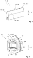
- FIG. 2 shows the first coupling element 10 with a parallelepiped, closing wedge holder 13, on whose longitudinal sides in each case a closing wedge 11 and 12 in each case a groove 13a of the closing wedge holder 13 displaceable in the z-direction are stored.
- the closing wedges 11 and 12 are each formed at their free end faces 11a and 12a to form two wedge surfaces 11b and 12b with a symmetrical wedge-shaped cross section.
- the two locking wedges 11 and 12 have a locking lug 11c and 12c, as shown in FIG. 2 is shown; a single striker 11 and 12, respectively FIG. 3 , After this, this locking lug 11c and 12c is perpendicular to the center of the side edge 11a and 12a and therefore extends in the vehicle vertical direction (z-direction).
- the striker holder 13 of the first coupling element 10 is on the front side 3b of the vehicle door 2 according to FIG. 1 arranged.
- a motor drive device 30 and an operative connection between the locking wedges 11 and 12 and this drive device 30 producing effective connection means are arranged.
- This drive device 30 is connected via the housing with the door stiffening element 5.
- the second coupling element 20 of the vehicle lock device 1 comprises two on a base plate 25 spaced-apart holding jaws 21 and 23 which receive between them the striker holder 13 with the two locking wedges 11 and 12, as shown in FIG FIG. 1 is shown.
- This second coupling element 20 is connected to an in FIG. 4 schematically indicated B-pillar 6 of the vehicle 40 is mounted, so that by closing the vehicle door 2 of the striker holder 13 with the two locking wedges 11 and 12 between the two holding jaws 21 and 23 according to FIG. 1 passes and locked there with the second coupling element 20 and coupled.
- the two holding jaws 21 and 23 each have a keyway 22 and 24 with wedge surfaces 22a and 24a, in the coupling and locking of the two coupling elements 10 and 20, the locking wedges 11 and 12 by means of the drive device 30 by extending out of the grooves 13a of the striker holder 13 are pressed.
- the locking lugs 11c and 12c of the two locking wedges 11 and 12 engage in a closing opening 22b and 24b of the keyways 22 and 24 of the two holding jaws 21 and 23, wherein these closing openings 22b and 24b form fit to the locking lugs 11c and 12c are adapted to thereby achieve a positive connection in the y-direction of the vehicle 40, ie both inwardly and outwardly.
- FIGS. 5, 6 and 7 an alternative embodiment of a locking lug is shown.
- the semicircular groove 11d of the closing wedge 11 and the length of the closing wedge guiding element 15 can be adapted to one another in this way, that in the retracted in the striker holder 13 state, the upper end face of the striker guide element 15 is aligned with the closing keeper holder 13 frontally.
- the extension of the locking wedge 11 and the retraction of the shooting wedge 11 in the keyway 22 of the holding jaw 21 and the closing wedge guide element moves as a locking lug 15 as shown in FIG FIG. 6 from and into a this closing wedge guide element 15 adapted semi-circular groove 21a of the holding jaw 21 of the second coupling element 20, as shown schematically in FIG FIG. 7 is shown.
- FIG. 1 can in the lower part of the vehicle door 2 at the lock-side end face 3b a Zuzie Vietnamese silkan extract 7 are arranged with a locking hook which engages in a arranged on the opposite B-pillar 6 bracket.
- a Zuzie Vietnamese silkan extract 7 are arranged with a locking hook which engages in a arranged on the opposite B-pillar 6 bracket.
- Such a bracket could also be arranged on the sill or be designed as a body-high bracket.
Landscapes
- Engineering & Computer Science (AREA)
- Structural Engineering (AREA)
- Lock And Its Accessories (AREA)
Description
- Die Erfindung betrifft eine Fahrzeugschlosseinrichtung für ein Fahrzeug unter Verwendung einer Kupplungsvorrichtung gemäß der
DE 10 2012 011 420 A1 . - Die aus der
DE 10 2012 011 420 A1 bekannte Kupplungsvorrichtung eines Fahrzeugs zur lösbaren Verbindung eines schwenkbeweglich gelagerten Karosserieteils, insbesondere einer Fahrzeugtüre, Heck- oder Frontklappe mit einem Fahrzeugstrukturteil, umfasst ein erstes, mit zwei parallel gegeneinander verschiebbar gelagerten Schließkeilen mit Keilflächen ausgebildetes Kupplungselement und ein mit diesem zusammenwirkendes zweites Kupplungselement, wobei im gekoppelten Zustand der Kupplungsvorrichtung über aneinander liegende Keilflächen das erste und zweite Kupplungselement spielfrei gekoppelt sind. Das zweite Kupplungselement ist mit zwei, das erste Kupplungselement zwischen sich aufnehmenden Haltebacken mit Keilflächen aufweisenden Keilnuten ausgebildet, derart dass mittels einer motorischen Antriebsvorrichtung die Schließkeile durch auseinander Verlagern mit ihren Keilflächen in die Keilnuten unter Anlage an deren Keilflächen gedrückt werden. - Mit dieser Kupplungsvorrichtung wird mit nur zwei Schließkeilen ein wirksamer Formschluss mit den Haltebacken des zweiten Kupplungselementes erzielt, nämlich in allen in der Ebene senkrecht zu den Schließkeilen liegenden Richtungen, sowohl in Fahrzeuglängsrichtung (x-Richtung) als auch in Fahrzeughochrichtung (z-Richtung). In der Richtung, in der die Schließkeile in die Keilnuten der Haltebacken gefahren werden, besteht ein hoher Kraftschluss.
- Ferner wird für diese aus der
DE 10 2012 011 420 A1 bekannten Kupplungsvorrichtung vorgeschlagen, wenigstens einen der Schließkeile auf der einer Haltebacke gegenüberliegenden Seitenkante mit einer Schließnase auszubilden, die in eine entsprechende Schließöffnung in der diesen Schließkeil aufnehmenden Keilnut einer Haltebacke des zweiten Kupplungselements beim Verriegeln einfährt. Dadurch wird auch in Fahrzeugquerichtung (y-Richtung), also sowohl in Richtung des Fahrzeuginneren als auch nach außen ein vollständiger Formschluss zwischen den beiden Kupplungselementen bewirkt. - Zudem ist bei einer Verwendung dieser bekannten Kupplungsvorrichtung zur lösbaren Kopplung einer geschlossenen Fahrzeugtüre mit einer B-Säule des Fahrzeugs ein übliches Fahrzeugschloss vorgesehen, wobei zur Betätigung des Fahrzeugschlosses als auch der Kupplungsvorrichtung ein Türinnen- und ein Türaußengriff vorgesehen ist. Der Einsatz sowohl einer Kupplungsvorrichtung als auch eines üblichen Fahrzeugschlosses führt zu hohen Material- und Montagekosten.
- Die
US 1 366 706 A beschreibt eine Kupplungsvorrichtung mit einem ersten Kupplungselement mit zwei parallel gegeneinander verschiebbar gelagerten Schließbolzen, wobei mit diesem ersten Kupplungselement ein zweites Kupplungselement mit zwei Haltebacken zusammenwirkt, indem die Schließbolzen in die beiden Haltebacken eingefahren werden. - Eine Kupplungsvorrichtung ist auch aus der
US 1 964 157 A bekannt, welche ein erstes Kupplungselement mit zwei parallel gegeneinander verschiebbar gelagerte Schließbolzen aufweist, die mit einem zweiten Kupplungselement zusammenwirkt, indem die beiden Schließbolzen in Haltebacken eingefahren werden. - Aufgabe der Erfindung ist es, eine Fahrzeugschlosseinrichtung anzugeben, welche kostengünstig realisiert werden kann.
- Diese Aufgabe wird gelöst durch eine Fahrzeugschlosseinrichtung mit den Merkmalen des Patentanspruchs 1.
- Hiernach wird als Fahrzeugschlosseinrichtung für ein Fahrzeug eine Kupplungsvorrichtung zur lösbaren Verbindung einer Fahrzeugtüre mit einem Fahrzeugstrukturteil mit folgenden Merkmalen verwendet:
- ein mit der Fahrzeugtüre verbundenes erstes Kupplungselement mit zwei parallel gegeneinander verschiebbar gelagerten Schließkeilen mit Keilflächen, wobei wenigstens einer der Schließkeile mit einer Schließnase ausgebildet ist,
- ein mit dem Fahrzeugstrukturteil verbundenes, mit dem ersten Kupplungselement zusammenwirkendes zweites Kupplungselement mit zwei, das erste Kupplungselement zwischen sich aufnehmenden Haltebacken mit Keilflächen aufweisenden Keilnuten, wobei mittels einer Antriebsvorrichtung die Schließkeile durch auseinander Verlagern mit ihren Keilflächen in die Keilnuten gedrückt werden und dabei die Schließnase in eine in einer Haltebacke angeordneten Schließöffnung aufgenommen wird, und
- zur Bildung eines Lastpfades ein in Fahrzeuglängsrichtung verlaufendes Türversteifungselement vorgesehen ist, welches mit einem Ende an der scharnierseitigen Stirnseite der Fahrzeugtüre angebunden ist und mit dem anderen Ende in dem Kupplungselement endet.
- Bei dieser Fahrzeugschlosseinrichtung übernimmt die aus der
DE 10 2012 011 420 A1 bekannte Kupplungsvorrichtung neben der Funktion der Kopplung der Fahrzeugtüre mit einer Karosserie-Säule, vorzugsweise der B-Säule auch die Funktion eines Fahrzeugschlosses, so dass auf ein herkömmliches Fahrzeugschloss verzichtet werden kann und dies zu Kosteneinsparungen führt. - Mit dieser die Fahrzeugschlossfunktion realisierenden Kopplung der Schließkeile mit den Schließbacken wird nicht nur ein Formschluss in Fahrzeuglängsrichtung (x-Richtung) und in Fahrzeughochrichtung (z-Richtung) bewirkt, sondern aufgrund der in eine Schließöffnung während der Verriegelung der ersten und zweiten Kupplungselemente einfahrenden Schließöffnung auch in Fahrzeugquerrichtung (y-Richtung). Damit eingeschlossen ist auch ein Formschluss bezüglich einer Drehung um Achsen in x-, y- und z-Richtung. Gemäß einer Ausgestaltung der Erfindung ist die Schließnase auf einer keilseitigen Stirnseite des Schließkeils ausgebildet und die zugehörige Schließöffnung in einer Keilnut der Haltebacke angeordnet.
- Alternativ ist weiterbildungsgemäß die Schließnase als Schließkeilführungselement ausgebildet, welche in z-Richtung in einer von jeweils dem Schließkeil und der Haltbacke gebildeten Halbnut geführt und mit dem auseinander Verlagern der Schließkeile aus einer eingezogenen Position in eine Schließöffnung der Haltebacke eingefahren wird.
- Die Erfindung wird nachfolgend anhand eines Ausführungsbeispiels unter Bezugnahme auf die beigefügten Figuren ausführlich beschrieben. Es zeigen:
- Figur 1:
- eine schematische und perspektivische Darstellung einer Fahrzeugtüre, welche mittels einer erfindungsgemäßen Fahrzeugschlosseinrichtung mit einer B-Säule verbunden ist,
- Figur 2
- eine schematische und perspektivische Darstellung des gemäß
Figur 1 an der Fahrzeugtüre angeordneten ersten Kupplungselementes der als Fahrzeugschlosseinrichtung verwendeten Kupplungsvorrichtung, - Figur 3
- eine schematische und perspektivische Darstellung eines Schließkeils mit Schließnase des ersten Kupplungselementes gemäß
Figur 2 , - Figur 4
- eine schematische und perspektivische Darstellung des gemäß
Figur 1 an der B-Säule angeordneten zweiten Kupplungselementes der als Fahrzeugschlosseinrichtung verwendeten Kupplungsvorrichtung, - Figur 5
- eine schematische und perspektivische Teildarstellung eines ersten Kupplungselementes mit eingefahrenem Schließkeil in einer alternativen Ausführung der Schließnase,
- Figur 6
- eine perspektivische Darstellung des Schließkeilhalters nach
Figur 5 mit ausgefahrenem Schließkeil und ausgefahrener Schließnase, und - Figur 7
- eine Detailansicht auf den Schließkeilhalter nach
Figur 6 im gekoppelten Zustand mit einer Haltebacke. -
Figur 1 zeigt eine Fahrzeugtüre 2 eines Fahrzeugs 40, bspw. eines Kraftfahrzeugs, welche über eine Fahrzeugschlosseinrichtung 1 mit einer B-Säule des Fahrzeugs 40 im Sinne einer Schlossfunktion verbindbar ist und damit das Fahrzeug 40 verschließ- und verriegelbar ist. - Diese Fahrzeugschlosseinrichtung 1 stellt eine aus der
DE 10 2012 011 420 bekannte Kupplungsvorrichtung dar und übernimmt die Fahrzeugschlossfunktion des Fahrzeugs 40. Diese Kupplungsvorrichtung 1 umfasst ein mit der Fahrzeugtüre 2 verbundenes erstes Kupplungselement 10 und ein an der B-Säule 6 montiertes zweites Kupplungselement 20, die zur Herstellung einer lösbaren Verbindung miteinander gekoppelt werden. - Die Fahrzeugtüre 2 ist in einer Sicht von außen dargestellt und zeigt einen Aufbau aus einem rahmen- und wannenartigen Türrahmen 3, im Folgenden äußeres Türinnenteil genannt und einem ebenso wannenartigen inneren Türinnenteil 4 mit Durchbrüchen, welches randseitig mit einem inneren umlaufenden Rand des äußeren Türinnenteils 3 verbunden ist und als Modulträger für Funktionsteile der Fahrzeugtüre 2 dient.
- Mit dem Bezugszeichen 3a ist eine scharnierseitige bzw. anschlagseitige Stirnseite der Fahrzeugtüre 2 bzw. des äußeren Türinnenteils 3 bezeichnet; die über Scharniere (nicht dargestellt) mit einer A-Säule des Kraftfahrzeugs 40 schwenkbar angelenkt wird. Die gegenüberliegende Stirnseite 3b ist die schlossseitige Stirnseite der Fahrzeugtüre 2 bzw. des äußeren Türinnenteils 3. Nach außen wird die Fahrzeugtüre 2 durch ein Außenblech (nicht dargestellt) und nach innen durch eine Türinnenverkleidung komplettiert (nicht dargestellt), so dass im Bereich der inneren und äußeren Türinnenteile 3 und 4 ein Türkasten zur Aufnahme von Funktionsteilen und einer Fensterscheibe (nicht dargestellt) entsteht, wobei die Fensterscheibe sich über den oberen Rand 3c des äußeren Türinnenteils 3 hinaus erstreckt. Der untere Rand 3d des äußeren Türinnenteils 3 befindet sich im Bereich eines Schwellers des Fahrzeugs 40.
- Die Fahrzeugtüre 2 gemäß
Figur 1 weist im oberen Bereich des äußeren Türinnenteils 3 ein die beiden Stirnseiten 3a und 3b in Fahrzeuglängsrichtung, also in x-Richtung verbindendes Türversteifungselement 5 auf, welches bspw. als U-Profil ausgebildet ist. Das eine Ende 5a dieses Türversteifungselementes 5 ist im oberen Bereich der scharnierseitigen Stirnseite 3a des äußeren Türinnenteils 3 angebunden, während das anderen Ende 5b mit der schlossseitigen Stirnseite 3b verbunden ist und gleichzeitig in dem ersten Kupplungselement 10 endet, welches im geschlossenen Zustand mit an der benachbarten B-Säule 6 angeordneten zweiten Kupplungselement 20 gekoppelt wird, so dass durch das Türversteifungselement 5 über das erste Kupplungselement 10 und das zweite Kupplungselement 20 ein Lastpfad entsteht und dadurch zum einen die Steifigkeit der Fahrzeugtüre 2 erhöht und zum anderen durch die Kraftkopplung über die beiden Kupplungselemente 10 und 20 mit der B-Säule 6 auch die Verwindungssteifigkeit der Fahrzeugkarosserie verbessert wird. - Im Folgenden wird der Aufbau sowie die Wirkungsweise des die Fahrzeugschlossfunktion übernehmenden Kupplungsvorrichtung 1 anhand der
Figuren 2 bis 4 beschrieben. -
Figur 2 zeigt das erste Kupplungselement 10 mit einem quaderförmigen , Schließkeilhalter 13, an dessen Längsseiten jeweils ein Schließkeil 11 und 12 in jeweils einer Nut 13a des Schließkeilhalters 13 verschiebbar in z-Richtung gelagert sind. Die Schließkeile 11 und 12 sind jeweils an ihren freien Stirnseiten 11a und 12a unter Bildung von jeweils zwei Keilflächen 11b und 12b mit einem symmetrischen keilförmigen Querschnitt ausgebildet. - Ferner weisen die beiden Schließkeile 11 und 12 eine Schließnase 11c bzw. 12c auf, wie dies in
Figur 2 dargestellt ist; einen einzelnen Schließkeil 11 bzw. 12 zeigtFigur 3 . Hiernach steht diese Schließnase 11c bzw. 12c senkrecht mittig auf der Seitenkante 11a bzw. 12a und erstreckt sich daher in Fahrzeughochrichtung (z-Richtung). - Der Schließkeilhalter 13 des ersten Kupplungselementes 10 ist an der Stirnseite 3b der Fahrzeugtüre 2 gemäß
Figur 1 angeordnet. Innerhalb der Fahrzeugtüre 2 sind eine motorische Antriebsvorrichtung 30 und eine Wirkverbindung zwischen den Schließkeilen 11 und 12 und dieser Antriebsvorrichtung 30 herstellende Wirkverbindungsmittel (in den Figuren nicht dargestellt) angeordnet. Diese Antriebsvorrichtung 30 ist über deren Gehäuse mit dem Türversteifungselement 5 verbunden. - Das zweite Kupplungselement 20 der Fahrzeugschlosseinrichtung 1 nach
Figur 4 umfasst zwei auf einer Grundplatte 25 zueinander beabstandet angeordnete Haltebacken 21 und 23, die zwischen sich den Schließkeilhalter 13 mit den beiden Schließkeilen 11 und 12 aufnehmen, wie dies inFigur 1 dargestellt ist. Dieses zweite Kupplungselement 20 ist an einer inFigur 4 schematisch angedeutet B-Säule 6 des Fahrzeugs 40 montiert, so dass durch das Schließen der Fahrzeugtüre 2 der Schließkeilhalter 13 mit den beiden Schließkeilen 11 und 12 zwischen die beiden Haltebacken 21 und 23 gemäßFigur 1 gelangt und dort mit dem zweiten Kupplungselement 20 verriegelt bzw. gekoppelt wird. Hierzu weisen die beiden Haltebacken 21 und 23 jeweils eine Keilnut 22 bzw. 24 mit Keilflächen 22a bzw. 24a auf, in die zum Koppeln und Verriegeln der beiden Kupplungselemente 10 und 20 die Schließkeile 11 und 12 mittels der Antriebsvorrichtung 30 durch Ausfahren aus den Nuten 13a des Schließkeilhalters 13 gedrückt werden. - Gleichzeitig mit einem solchen Kopplungs- und Verriegelungsvorgang greifen auch die Schließnasen 11c und 12c der beiden Schließkeile 11 und 12 in eine Schließöffnung 22b und 24b der Keilnuten 22 und 24 der beiden Haltebacken 21 und 23 ein, wobei diese Schließöffnungen 22b und 24b formschlüssig an die Schließnasen 11c und 12c angepasst sind, um dadurch einen Formschluss in y-Richtung des Fahrzeugs 40, also sowohl nach innen als auch nach außen zu erreichen.
- Mit einer solchen Kupplungsvorrichtung 1 mit einem ersten und zweiten Kupplungselement 10 bzw. 20 wird eine vollständige Fahrzeugschlossfunktion realisiert, wobei hierzu insbesondere die beiden in die Schließöffnungen 22b und 24b einfahrenden Schließnasen 11c und 12c der beiden Schließkeile 11 und 12 beitragen.
- Es ist auch möglich nur einen der beiden Schließkeile 11 oder 12 mit einer solchen Schließnase 11c oder 12c auszubilden, ohne dadurch die Fahrzeugschlossfunktion einzuschränken.
- In den
Figuren 5, 6 und 7 ist eine alternative Ausführung einer Schließnase dargestellt. - Zur Führung der Schließkeile 11 und 12 in dem Schließkeilhalter 13 sind jeweils miteinander korrespondierende Halbkreisnuten 14 an dem Schließkeilhalter 13 und Halbkreisnuten 11d an dem Schließkeil 11 vorgesehen, so dass die dadurch gebildeten Hohlzylinder jeweils ein Schließkeilführungselement 15 aufnehmen können, welches als Schließnase 15 verwendet wird. Eine entsprechende Ausgestaltung ist auch an der gegenüberliegenden Haltebacke 12 vorgesehen.
- Gemäß
Figur 5 kann die Halbkreisnut 11d des Schließkeils 11 und die Länge des Schließkeilführungselementes 15 so aufeinander angepasst werden, dass im in den Schließkeilhalter 13 eingefahrenen Zustand die obere Stirnseite des Schließkeilführungselementes 15 mit dem Schließkeilhalter 13 stirnseitig fluchtet. Mit dem Ausfahren des Schließkeils 11 bzw. dem Einfahren des Schießkeils 11 in die Keilnut 22 des Haltebackens 21 fährt auch das Schließkeilführungselement als Schließnase 15 entsprechend der Darstellung inFigur 6 aus und in eine an dieses Schließkeilführungselement 15 angepasste halbkreisförmige Nut 21a der Haltebacke 21 des zweiten Kupplungselementes 20 ein, wie dies schematisch inFigur 7 dargestellt ist. - Gemäß
Figur 1 kann im unteren Bereich der Fahrzeugtüre 2 an deren schlossseitigen Stirnseite 3b eine Zuziehilfeanordnung 7 mit einem Schließhaken angeordnet werden, der in einen an der gegenüberliegenden B-Säule 6 angeordneten Bügel eingreift. Ein solcher Bügel könnte auch am Schweller angeordnet sein oder als karosserierohbaufester Bügel ausgebildet sein. -
- 1
- Fahrzeugschlosseinrichtung, Kupplungsvorrichtung
- 2
- Fahrzeugtür
- 3
- Türrahmen
- 3a
- scharnierseitige Stirnseite des äußeren Türinnenteils 2
- 3b
- schlossseitige Stirnseite des äußeren Türinnenteils 2
- 3c
- obere Rand des äußeren Türinnenteils 2
- 3d
- untere Rand des äußeren Türinnenteils 2
- 4
- inneres Türinnenteil
- 5
- Türversteifungselement
- 6
- B-Säule einer Fahrzeugkarosserie
- 7
- Zuziehhilfeanordnung
- 10
- erstes Kupplungselement
- 11
- Schließkeil
- 11a
- Seitenkante des Schließkeils 11
- 11b
- Keilflächen der Seitenkante 11a
- 11c
- Schließnase des Schließkeils 11
- 11d
- Halbkreisnut des Schließkeils 11
- 12
- Schließkeil
- 12a
- Seitenkante des Schließkeils 12
- 12b
- Keilflächen der Seitenkante 12a
- 12d
- Schließnase des Schließkeils 12
- 13
- Schließkeilhalter
- 13a
- Nut des Schließkeilhalters 13
- 14
- Führungsnut des Schließkeilhalters für Schließkeilführungselement 15
- 15
- Schließnase des Schließkeils 11, Schließkeilführungselement
- 20
- zweites Kupplungselement
- 21
- Haltebacke des zweiten Kupplungselementes 20
- 21a
- Schließöffnung der Haltebacke 21
- 22
- Keilnut der Haltebacke 21
- 22a
- Keilflächen der Keilnut 22
- 22b
- Schließöffnung der Keilnut 22
- 23
- Haltebacke des zweiten Kupplungselementes 20
- 24
- Keilnut der Haltebacke 23
- 24a
- Keilflächen der Keilnut 24
- 24b
- Schließöffnung der Keilnut 24
- 25
- Grundplatte
- 30
- Antriebsvorrichtung
- 40
- Fahrzeug, Kraftfahrzeug
Claims (4)
- Fahrzeugschlosseinrichtung (1) für ein Fahrzeug unter Verwendung einer Kupplungsvorrichtung zur lösbaren Verbindung einer Fahrzeugtür (2) mit einem Fahrzeugstrukturteil (6), umfassend- ein mit der Fahrzeugtür (2) verbundenes erstes Kupplungselement (10) mit zwei parallel gegeneinander verschiebbar gelagerten Schließkeilen (11, 12) mit Keilflächen (11b, 12b), wobei wenigstens einer der Schließkeile (11, 12) mit einer Schließnase (11c, 12c, 15) ausgebildet ist,- ein mit dem Fahrzeugstrukturteil (6) verbundenes , mit dem ersten Kupplungselement (10) zusammenwirkendes zweites Kupplungselement (20) mit zwei, das erste Kupplungselement (10) zwischen sich aufnehmenden Haltebacken (21, 23) mit Keilflächen (22a, 24a) aufweisenden Keilnuten (22, 24), wobei mittels einer Antriebsvorrichtung (30) die Schließkeile (11, 12) durch auseinander Verlagern mit ihren Keilflächen (11b, 12b) in die Keilnuten (22, 24) gedrückt werden und dabei die Schließnase (11c, 12c, 15) in eine in einer Haltebacke (21, 23) angeordneten Schließöffnung (21a, 22b, 24b) aufgenommen wird, und- zur Bildung eines Lastpfades ein in Fahrzeuglängsrichtung verlaufendes Türversteifungselement (5) vorgesehen ist, welches mit einem Ende (5a) an der scharnierseitigen Stirnseite (3a) der Fahrzeugtüre (2) angebunden ist und mit dem anderen Ende (5b) in dem Kupplungselement (10) endet.
- Fahrzeugschlosseinrichtung (1) nach Anspruch 1,
dadurch gekennzeichnet, dass die Schiießnase (11c, 12c) auf einer keilseitigen Stirnseite (11a, 12a) des Schließkeils (11, 12) ausgebildet ist und die zugehörige Schließöffnung in einer Keilnut (22, 24) der Haltebacke (21, 23) angeordnet ist. - Fahrzeugschlosseinrichtung (1) nach Anspruch 1,
dadurch gekennzeichnet, dass die Schließnase als Schließkeilführungselement (15) ausgebildet ist, welche in z-Richtung in einer von jeweils dem Schließkeil (11, 12) und der Haltbacke (21, 23) gebildeten Halbnut (11d, 14) geführt und mit dem auseinander Verlagern der Schließkeile (11, 12) aus einer eingezogenen Position in eine Schließöffnung (21a) der Haltebacke (21, 23) eingefahren wird. - Fahrzeugschlosseinrichtung (1) nach einem der vorhergehenden Ansprüche,
dadurch gekennzeichnet, dass das Fahrzeugstrukturteil (6) eine Karosseriesäule, vorzugsweise ein B-Säule ist.
Applications Claiming Priority (2)
| Application Number | Priority Date | Filing Date | Title |
|---|---|---|---|
| DE102012025336.2A DE102012025336A1 (de) | 2012-12-21 | 2012-12-21 | Fahrzeugschlosseinrichtung für ein Fahrzeug unter Verwendung einer Kupplungsvorrichtung |
| PCT/EP2013/003881 WO2014095077A2 (de) | 2012-12-21 | 2013-12-20 | Fahrzeugschlosseinrichtung für ein fahrzeug unter verwendung einer kupp lungsvorrichtung |
Publications (2)
| Publication Number | Publication Date |
|---|---|
| EP2935734A2 EP2935734A2 (de) | 2015-10-28 |
| EP2935734B1 true EP2935734B1 (de) | 2018-02-21 |
Family
ID=49918664
Family Applications (1)
| Application Number | Title | Priority Date | Filing Date |
|---|---|---|---|
| EP13817888.4A Not-in-force EP2935734B1 (de) | 2012-12-21 | 2013-12-20 | Fahrzeugschlosseinrichtung für ein fahrzeug unter verwendung einer kupp lungsvorrichtung |
Country Status (6)
| Country | Link |
|---|---|
| US (1) | US10041276B2 (de) |
| EP (1) | EP2935734B1 (de) |
| CN (1) | CN104884718B (de) |
| DE (1) | DE102012025336A1 (de) |
| ES (1) | ES2663388T3 (de) |
| WO (1) | WO2014095077A2 (de) |
Families Citing this family (7)
| Publication number | Priority date | Publication date | Assignee | Title |
|---|---|---|---|---|
| DE102012025336A1 (de) * | 2012-12-21 | 2014-06-26 | Audi Ag | Fahrzeugschlosseinrichtung für ein Fahrzeug unter Verwendung einer Kupplungsvorrichtung |
| DE102012025392B3 (de) * | 2012-12-24 | 2014-02-20 | Audi Ag | Abdeckvorrichtung für ein mit einem Schließkeilmodul in eine die Verbindung einer Fahrzeugtüre mit einem Seitenwandrahmen einer Fahrzeugkarosserie bewirkende lösbare Kopplung bringbares Haltebackenmodul |
| DE102014012466B4 (de) * | 2014-08-21 | 2016-03-10 | Audi Ag | Schließkeilsystem als Fahrzeugklappenschloss |
| DE102016004279A1 (de) * | 2016-04-07 | 2017-10-12 | Audi Ag | Schließkeilsystem zur lösbaren Kopplung einer Fahrzeugklappe mit einem Strukturteil einer Fahrzeugkarosserie |
| US10619385B2 (en) * | 2016-06-02 | 2020-04-14 | Magna Closures Inc. | Closure latch for a rear vehicle door having an emergency child lock release mechanism |
| US11598119B2 (en) * | 2019-08-17 | 2023-03-07 | Travis Brett Creighton | Securable deadbolt, hinge, and sliding assemblies |
| DE102020003194A1 (de) * | 2020-05-28 | 2021-06-02 | Daimler Ag | Personenkraftwagen mit verbessertem Seitenaufprallschutz |
Citations (1)
| Publication number | Priority date | Publication date | Assignee | Title |
|---|---|---|---|---|
| DE102012011420A1 (de) * | 2012-06-08 | 2013-12-12 | Audi Ag | Kupplungsvorrichtung zur lösbaren Verbindung eines schwenkbeweglich gelagerten Karosserieteils, wie Fahrzeugtüre, Heck- oder Frontklappe mit einem Fahrzeugstrukturteil einer Fahrzeugkarosserie |
Family Cites Families (38)
| Publication number | Priority date | Publication date | Assignee | Title |
|---|---|---|---|---|
| US1081927A (en) * | 1908-11-02 | 1913-12-16 | George H Forsyth | Car construction. |
| US1366706A (en) * | 1920-09-17 | 1921-01-25 | Yale & Towne Mfg Co | Lock |
| US1964157A (en) * | 1925-03-12 | 1934-06-26 | Holtzman John | Hand operated lock |
| US1757021A (en) * | 1927-02-07 | 1930-05-06 | Frederick W Renworth | Automobile hood-retaining means |
| US1965672A (en) * | 1930-09-19 | 1934-07-10 | Mitchell Specialty Company | Door retainer |
| US2344826A (en) * | 1942-02-25 | 1944-03-21 | Gresley Stanley G Le | Safety vehicle door lock |
| US2489957A (en) * | 1948-04-28 | 1949-11-29 | Mary Davis Miller | Latch mechanism |
| US2869952A (en) * | 1957-04-24 | 1959-01-20 | Gen Motors Corp | Door latch |
| US2973984A (en) * | 1959-07-27 | 1961-03-07 | Charles E Burke | Vehicle door bolt lock |
| DE1703285A1 (de) * | 1968-04-27 | 1972-01-13 | Nolden Celina Willimzik Geb | Vorrichtung zum Arretieren,Ausrichten und selbsttaetigen Verriegeln von Tueren an Moebelstuecken |
| US3583737A (en) * | 1969-11-07 | 1971-06-08 | Zenzi Tutikawa | Locking apparatus for set of swinging doors |
| US3610668A (en) * | 1969-12-22 | 1971-10-05 | Renault | Automotive door locks |
| DE2745120C2 (de) * | 1977-10-07 | 1979-10-11 | Daimler-Benz Ag, 7000 Stuttgart | Türführung, insbesondere für die Hecktüre eines Kombinationskraftwagens |
| FR2539794B1 (fr) * | 1983-01-26 | 1988-01-29 | Citroen Sa | Serrure du type saillant rapporte, notamment pour vehicule automobile |
| US4940282A (en) * | 1985-10-03 | 1990-07-10 | Townsend John A | Chassis frame for a wheeled motor vehicle |
| DE3921289C1 (de) * | 1989-06-29 | 1991-01-10 | Brose Fahrzeugteile Gmbh & Co Kg, 8630 Coburg, De | |
| GB9018350D0 (en) * | 1990-08-21 | 1990-10-03 | Jaguar Cars | Vehicle bodies |
| DE9105557U1 (de) * | 1991-04-30 | 1991-09-05 | Martin Lehmann GmbH & Co KG, 4950 Minden | Schubriegelschloß |
| US5806917A (en) * | 1995-12-22 | 1998-09-15 | Joalto Design, Inc. | Integrated motor vehicle door and chassis |
| US6196619B1 (en) * | 1995-12-22 | 2001-03-06 | Joalto Design, Inc. | Vehicle closure panel having an intrusion beam as primary structure |
| US5992927A (en) * | 1995-12-29 | 1999-11-30 | Emhart Inc. | Wedge and striker assembly for automotive doors and door frames |
| US5715712A (en) * | 1996-06-03 | 1998-02-10 | West; Marlon | Vehicle door safety and theft resistant lock |
| DE19654956B4 (de) * | 1996-06-04 | 2005-06-23 | Brose Fahrzeugteile Gmbh & Co. Kommanditgesellschaft, Coburg | Kraftfahrzeugtür |
| US6345849B1 (en) * | 1999-11-01 | 2002-02-12 | Si-Kang Yen | Safety door stopper |
| US6676201B2 (en) * | 2002-03-05 | 2004-01-13 | General Motors Corporation | Wedge system for liftgate of vehicle |
| ITTO20020138U1 (it) * | 2002-07-23 | 2004-01-23 | Repetti S R L | Gruppo per l'apertura di emergenza di una porta di un autoveicolo. |
| DE10315565B4 (de) * | 2003-04-05 | 2006-07-13 | Audi Ag | Fahrzeugkarosserie und Kraftschloß |
| DE10348500B4 (de) * | 2003-10-18 | 2009-07-30 | Inos Automationssoftware Gmbh | Verfahren und Vorrichtung zum Erfassen eines Spaltmaßes und/oder eines Versatzes zwischen einer Klappe eines Fahrzeugs und der übrigen Fahrzeugkarosserie |
| US7258381B2 (en) * | 2005-05-23 | 2007-08-21 | International Automotive Components Group North America, Inc. | Modular vehicle interior component system and release latch mechanism for use with the system |
| DE102008009506A1 (de) | 2008-02-15 | 2009-08-20 | Kiekert Ag | Kraftfahrzeugtürverschluss |
| EP2093107B1 (de) * | 2008-02-21 | 2012-10-17 | GM Global Technology Operations LLC | Lagerung eines Containers in einem Fahrgastraum eines Kraftfahrzeugs |
| GB2470701C (en) * | 2008-03-11 | 2013-03-20 | Piotr Leonard Kowalczyk | Lock |
| US8322762B2 (en) * | 2009-02-27 | 2012-12-04 | Nissan North America, Inc. | Door gap adjustment for a motor vehicle |
| CN201794371U (zh) | 2010-07-03 | 2011-04-13 | 燕山大学 | 汽车门锁应急开启装置 |
| JP5633314B2 (ja) * | 2010-11-04 | 2014-12-03 | アイシン精機株式会社 | 車両ドア固定装置及びその可動楔装置 |
| DE102012025336A1 (de) * | 2012-12-21 | 2014-06-26 | Audi Ag | Fahrzeugschlosseinrichtung für ein Fahrzeug unter Verwendung einer Kupplungsvorrichtung |
| US9428092B2 (en) * | 2014-06-09 | 2016-08-30 | Honda Motor Co., Ltd. | Sliding and removable cup holder assembly for vehicle |
| JP6466659B2 (ja) * | 2014-06-24 | 2019-02-06 | 株式会社ユーシン | ドアロック装置 |
-
2012
- 2012-12-21 DE DE102012025336.2A patent/DE102012025336A1/de not_active Withdrawn
-
2013
- 2013-12-20 WO PCT/EP2013/003881 patent/WO2014095077A2/de not_active Ceased
- 2013-12-20 CN CN201380066371.3A patent/CN104884718B/zh not_active Expired - Fee Related
- 2013-12-20 EP EP13817888.4A patent/EP2935734B1/de not_active Not-in-force
- 2013-12-20 ES ES13817888.4T patent/ES2663388T3/es active Active
- 2013-12-20 US US14/654,204 patent/US10041276B2/en not_active Expired - Fee Related
Patent Citations (1)
| Publication number | Priority date | Publication date | Assignee | Title |
|---|---|---|---|---|
| DE102012011420A1 (de) * | 2012-06-08 | 2013-12-12 | Audi Ag | Kupplungsvorrichtung zur lösbaren Verbindung eines schwenkbeweglich gelagerten Karosserieteils, wie Fahrzeugtüre, Heck- oder Frontklappe mit einem Fahrzeugstrukturteil einer Fahrzeugkarosserie |
Also Published As
| Publication number | Publication date |
|---|---|
| WO2014095077A3 (de) | 2014-08-28 |
| DE102012025336A1 (de) | 2014-06-26 |
| ES2663388T3 (es) | 2018-04-12 |
| US10041276B2 (en) | 2018-08-07 |
| CN104884718B (zh) | 2017-03-08 |
| EP2935734A2 (de) | 2015-10-28 |
| CN104884718A (zh) | 2015-09-02 |
| WO2014095077A2 (de) | 2014-06-26 |
| US20150322697A1 (en) | 2015-11-12 |
Similar Documents
| Publication | Publication Date | Title |
|---|---|---|
| EP2935734B1 (de) | Fahrzeugschlosseinrichtung für ein fahrzeug unter verwendung einer kupp lungsvorrichtung | |
| EP2859165B1 (de) | Kupplungsvorrichtung zur lösbaren verbindung eines schwenkbeweglich gelagerten karosserieteils, wie fahrzeugtüre, heck- oder frontklappe mit einem fahrzeugstrukturteil einer fahrzeugkarosserie | |
| EP2935739B1 (de) | Abdeckvorrichtung für ein mit einem schliesskeilmodul in eine die verbindung einer fahrzeugtüre mit einem seitenwandrahmen einer fahrzeugkarosserie bewirkende lösbare kopplung bringbares haltebackenmodul | |
| DE102019128241A1 (de) | Türmodul mit rahmenloser glaskonfiguration mit einstellbaren glaslaufkanälen | |
| EP3622149B1 (de) | Schiene zur führung eines schlittens einer möbeltüre | |
| DE8309452U1 (de) | Tür eines Motorfahrzeuges | |
| DE102013113483A1 (de) | Schiebetüreinrichtung für die seitliche Türöffnung eines Personenkraftfahrzeugs; Personenkraftfahrzeug mit Schiebetüreinrichtung | |
| EP3299555B1 (de) | Riegel für drehtüren und/oder flügeltüren | |
| DE102020007856A1 (de) | Türanordnung einer Seitentür an einer Seitenwand eines Kraftwagens | |
| DE102018219092A1 (de) | Tür für ein Fahrzeug und korrespondierendes Fahrzeug | |
| DE202022100517U1 (de) | Profilanordnung eines Fensters oder einer Tür mit einem Flügelprofil, insbesondere einem Schiebeflügelprofil | |
| DE102012017865B4 (de) | Fahrzeugtüre für ein Fahrzeug mit einem Türschloss und einem Türaufprallträger | |
| EP1999331B1 (de) | Beschlag | |
| DE102004062167B4 (de) | Fensterheberanordnung | |
| DE60019892T2 (de) | Fensterhebevorrichtung für motorfahrzeuge | |
| EP1669231A2 (de) | Faltschiebetür für Kraftfahrzeuge | |
| DE102020112528A1 (de) | Kraftfahrzeug mit einer Karosserie | |
| EP4446204A1 (de) | Seitlicher heckbereich eines kraftfahrzeugs mit einer luftleitvorrichtung und kraftfahrzeug | |
| DE102007050398A1 (de) | Kraftfahrzeugtür | |
| EP2835487A1 (de) | Klappeneinrichtung eines Gebäudes | |
| EP2987932A1 (de) | Schliesskeilsystem als fahrzeugklappenschloss | |
| EP3440293B1 (de) | Schliesskeilsystem zur lösbaren kopplung einer fahrzeugklappe mit einem strukturteil einer fahrzeugkarosserie | |
| DE3425777C2 (de) | Kraftwagentür | |
| EP4363681B1 (de) | Stangenverschluss | |
| DE102014111131A1 (de) | Vorrichtung zur Ver- und Entriegelung eines Fensterflügels, einer Lüftungsklappe oder dergleichen an einem Blendrahmen |
Legal Events
| Date | Code | Title | Description |
|---|---|---|---|
| PUAI | Public reference made under article 153(3) epc to a published international application that has entered the european phase |
Free format text: ORIGINAL CODE: 0009012 |
|
| 17P | Request for examination filed |
Effective date: 20150721 |
|
| AK | Designated contracting states |
Kind code of ref document: A2 Designated state(s): AL AT BE BG CH CY CZ DE DK EE ES FI FR GB GR HR HU IE IS IT LI LT LU LV MC MK MT NL NO PL PT RO RS SE SI SK SM TR |
|
| AX | Request for extension of the european patent |
Extension state: BA ME |
|
| RIN1 | Information on inventor provided before grant (corrected) |
Inventor name: LE GRIFFON, JEAN-BERNARD Inventor name: SCHOCH, MARION |
|
| DAX | Request for extension of the european patent (deleted) | ||
| 17Q | First examination report despatched |
Effective date: 20161220 |
|
| GRAP | Despatch of communication of intention to grant a patent |
Free format text: ORIGINAL CODE: EPIDOSNIGR1 |
|
| INTG | Intention to grant announced |
Effective date: 20171025 |
|
| GRAS | Grant fee paid |
Free format text: ORIGINAL CODE: EPIDOSNIGR3 |
|
| GRAA | (expected) grant |
Free format text: ORIGINAL CODE: 0009210 |
|
| AK | Designated contracting states |
Kind code of ref document: B1 Designated state(s): AL AT BE BG CH CY CZ DE DK EE ES FI FR GB GR HR HU IE IS IT LI LT LU LV MC MK MT NL NO PL PT RO RS SE SI SK SM TR |
|
| REG | Reference to a national code |
Ref country code: GB Ref legal event code: FG4D Free format text: NOT ENGLISH |
|
| REG | Reference to a national code |
Ref country code: CH Ref legal event code: EP |
|
| REG | Reference to a national code |
Ref country code: AT Ref legal event code: REF Ref document number: 971890 Country of ref document: AT Kind code of ref document: T Effective date: 20180315 |
|
| REG | Reference to a national code |
Ref country code: IE Ref legal event code: FG4D Free format text: LANGUAGE OF EP DOCUMENT: GERMAN |
|
| REG | Reference to a national code |
Ref country code: DE Ref legal event code: R096 Ref document number: 502013009515 Country of ref document: DE |
|
| REG | Reference to a national code |
Ref country code: ES Ref legal event code: FG2A Ref document number: 2663388 Country of ref document: ES Kind code of ref document: T3 Effective date: 20180412 |
|
| REG | Reference to a national code |
Ref country code: NL Ref legal event code: MP Effective date: 20180221 |
|
| REG | Reference to a national code |
Ref country code: LT Ref legal event code: MG4D |
|
| PG25 | Lapsed in a contracting state [announced via postgrant information from national office to epo] |
Ref country code: HR Free format text: LAPSE BECAUSE OF FAILURE TO SUBMIT A TRANSLATION OF THE DESCRIPTION OR TO PAY THE FEE WITHIN THE PRESCRIBED TIME-LIMIT Effective date: 20180221 Ref country code: LT Free format text: LAPSE BECAUSE OF FAILURE TO SUBMIT A TRANSLATION OF THE DESCRIPTION OR TO PAY THE FEE WITHIN THE PRESCRIBED TIME-LIMIT Effective date: 20180221 Ref country code: CY Free format text: LAPSE BECAUSE OF FAILURE TO SUBMIT A TRANSLATION OF THE DESCRIPTION OR TO PAY THE FEE WITHIN THE PRESCRIBED TIME-LIMIT Effective date: 20180221 Ref country code: NL Free format text: LAPSE BECAUSE OF FAILURE TO SUBMIT A TRANSLATION OF THE DESCRIPTION OR TO PAY THE FEE WITHIN THE PRESCRIBED TIME-LIMIT Effective date: 20180221 Ref country code: NO Free format text: LAPSE BECAUSE OF FAILURE TO SUBMIT A TRANSLATION OF THE DESCRIPTION OR TO PAY THE FEE WITHIN THE PRESCRIBED TIME-LIMIT Effective date: 20180521 Ref country code: FI Free format text: LAPSE BECAUSE OF FAILURE TO SUBMIT A TRANSLATION OF THE DESCRIPTION OR TO PAY THE FEE WITHIN THE PRESCRIBED TIME-LIMIT Effective date: 20180221 |
|
| PG25 | Lapsed in a contracting state [announced via postgrant information from national office to epo] |
Ref country code: SE Free format text: LAPSE BECAUSE OF FAILURE TO SUBMIT A TRANSLATION OF THE DESCRIPTION OR TO PAY THE FEE WITHIN THE PRESCRIBED TIME-LIMIT Effective date: 20180221 Ref country code: LV Free format text: LAPSE BECAUSE OF FAILURE TO SUBMIT A TRANSLATION OF THE DESCRIPTION OR TO PAY THE FEE WITHIN THE PRESCRIBED TIME-LIMIT Effective date: 20180221 Ref country code: GR Free format text: LAPSE BECAUSE OF FAILURE TO SUBMIT A TRANSLATION OF THE DESCRIPTION OR TO PAY THE FEE WITHIN THE PRESCRIBED TIME-LIMIT Effective date: 20180522 Ref country code: RS Free format text: LAPSE BECAUSE OF FAILURE TO SUBMIT A TRANSLATION OF THE DESCRIPTION OR TO PAY THE FEE WITHIN THE PRESCRIBED TIME-LIMIT Effective date: 20180221 Ref country code: BG Free format text: LAPSE BECAUSE OF FAILURE TO SUBMIT A TRANSLATION OF THE DESCRIPTION OR TO PAY THE FEE WITHIN THE PRESCRIBED TIME-LIMIT Effective date: 20180521 |
|
| PG25 | Lapsed in a contracting state [announced via postgrant information from national office to epo] |
Ref country code: MT Free format text: LAPSE BECAUSE OF FAILURE TO SUBMIT A TRANSLATION OF THE DESCRIPTION OR TO PAY THE FEE WITHIN THE PRESCRIBED TIME-LIMIT Effective date: 20180221 |
|
| PG25 | Lapsed in a contracting state [announced via postgrant information from national office to epo] |
Ref country code: AL Free format text: LAPSE BECAUSE OF FAILURE TO SUBMIT A TRANSLATION OF THE DESCRIPTION OR TO PAY THE FEE WITHIN THE PRESCRIBED TIME-LIMIT Effective date: 20180221 Ref country code: PL Free format text: LAPSE BECAUSE OF FAILURE TO SUBMIT A TRANSLATION OF THE DESCRIPTION OR TO PAY THE FEE WITHIN THE PRESCRIBED TIME-LIMIT Effective date: 20180221 Ref country code: EE Free format text: LAPSE BECAUSE OF FAILURE TO SUBMIT A TRANSLATION OF THE DESCRIPTION OR TO PAY THE FEE WITHIN THE PRESCRIBED TIME-LIMIT Effective date: 20180221 Ref country code: RO Free format text: LAPSE BECAUSE OF FAILURE TO SUBMIT A TRANSLATION OF THE DESCRIPTION OR TO PAY THE FEE WITHIN THE PRESCRIBED TIME-LIMIT Effective date: 20180221 |
|
| REG | Reference to a national code |
Ref country code: DE Ref legal event code: R097 Ref document number: 502013009515 Country of ref document: DE |
|
| PG25 | Lapsed in a contracting state [announced via postgrant information from national office to epo] |
Ref country code: SK Free format text: LAPSE BECAUSE OF FAILURE TO SUBMIT A TRANSLATION OF THE DESCRIPTION OR TO PAY THE FEE WITHIN THE PRESCRIBED TIME-LIMIT Effective date: 20180221 Ref country code: SM Free format text: LAPSE BECAUSE OF FAILURE TO SUBMIT A TRANSLATION OF THE DESCRIPTION OR TO PAY THE FEE WITHIN THE PRESCRIBED TIME-LIMIT Effective date: 20180221 Ref country code: CZ Free format text: LAPSE BECAUSE OF FAILURE TO SUBMIT A TRANSLATION OF THE DESCRIPTION OR TO PAY THE FEE WITHIN THE PRESCRIBED TIME-LIMIT Effective date: 20180221 Ref country code: DK Free format text: LAPSE BECAUSE OF FAILURE TO SUBMIT A TRANSLATION OF THE DESCRIPTION OR TO PAY THE FEE WITHIN THE PRESCRIBED TIME-LIMIT Effective date: 20180221 |
|
| PLBE | No opposition filed within time limit |
Free format text: ORIGINAL CODE: 0009261 |
|
| STAA | Information on the status of an ep patent application or granted ep patent |
Free format text: STATUS: NO OPPOSITION FILED WITHIN TIME LIMIT |
|
| 26N | No opposition filed |
Effective date: 20181122 |
|
| PG25 | Lapsed in a contracting state [announced via postgrant information from national office to epo] |
Ref country code: SI Free format text: LAPSE BECAUSE OF FAILURE TO SUBMIT A TRANSLATION OF THE DESCRIPTION OR TO PAY THE FEE WITHIN THE PRESCRIBED TIME-LIMIT Effective date: 20180221 |
|
| REG | Reference to a national code |
Ref country code: CH Ref legal event code: PL |
|
| PG25 | Lapsed in a contracting state [announced via postgrant information from national office to epo] |
Ref country code: LU Free format text: LAPSE BECAUSE OF NON-PAYMENT OF DUE FEES Effective date: 20181220 Ref country code: MC Free format text: LAPSE BECAUSE OF FAILURE TO SUBMIT A TRANSLATION OF THE DESCRIPTION OR TO PAY THE FEE WITHIN THE PRESCRIBED TIME-LIMIT Effective date: 20180221 |
|
| REG | Reference to a national code |
Ref country code: IE Ref legal event code: MM4A |
|
| REG | Reference to a national code |
Ref country code: BE Ref legal event code: MM Effective date: 20181231 |
|
| PG25 | Lapsed in a contracting state [announced via postgrant information from national office to epo] |
Ref country code: IE Free format text: LAPSE BECAUSE OF NON-PAYMENT OF DUE FEES Effective date: 20181220 |
|
| PG25 | Lapsed in a contracting state [announced via postgrant information from national office to epo] |
Ref country code: BE Free format text: LAPSE BECAUSE OF NON-PAYMENT OF DUE FEES Effective date: 20181231 |
|
| PG25 | Lapsed in a contracting state [announced via postgrant information from national office to epo] |
Ref country code: CH Free format text: LAPSE BECAUSE OF NON-PAYMENT OF DUE FEES Effective date: 20181231 Ref country code: LI Free format text: LAPSE BECAUSE OF NON-PAYMENT OF DUE FEES Effective date: 20181231 |
|
| REG | Reference to a national code |
Ref country code: AT Ref legal event code: MM01 Ref document number: 971890 Country of ref document: AT Kind code of ref document: T Effective date: 20181220 |
|
| PG25 | Lapsed in a contracting state [announced via postgrant information from national office to epo] |
Ref country code: TR Free format text: LAPSE BECAUSE OF FAILURE TO SUBMIT A TRANSLATION OF THE DESCRIPTION OR TO PAY THE FEE WITHIN THE PRESCRIBED TIME-LIMIT Effective date: 20180221 |
|
| PG25 | Lapsed in a contracting state [announced via postgrant information from national office to epo] |
Ref country code: AT Free format text: LAPSE BECAUSE OF NON-PAYMENT OF DUE FEES Effective date: 20181220 |
|
| PG25 | Lapsed in a contracting state [announced via postgrant information from national office to epo] |
Ref country code: PT Free format text: LAPSE BECAUSE OF FAILURE TO SUBMIT A TRANSLATION OF THE DESCRIPTION OR TO PAY THE FEE WITHIN THE PRESCRIBED TIME-LIMIT Effective date: 20180221 |
|
| PG25 | Lapsed in a contracting state [announced via postgrant information from national office to epo] |
Ref country code: MK Free format text: LAPSE BECAUSE OF NON-PAYMENT OF DUE FEES Effective date: 20180221 Ref country code: HU Free format text: LAPSE BECAUSE OF FAILURE TO SUBMIT A TRANSLATION OF THE DESCRIPTION OR TO PAY THE FEE WITHIN THE PRESCRIBED TIME-LIMIT; INVALID AB INITIO Effective date: 20131220 |
|
| PG25 | Lapsed in a contracting state [announced via postgrant information from national office to epo] |
Ref country code: IS Free format text: LAPSE BECAUSE OF FAILURE TO SUBMIT A TRANSLATION OF THE DESCRIPTION OR TO PAY THE FEE WITHIN THE PRESCRIBED TIME-LIMIT Effective date: 20180621 |
|
| PGFP | Annual fee paid to national office [announced via postgrant information from national office to epo] |
Ref country code: IT Payment date: 20201231 Year of fee payment: 8 |
|
| PGFP | Annual fee paid to national office [announced via postgrant information from national office to epo] |
Ref country code: ES Payment date: 20210108 Year of fee payment: 8 |
|
| REG | Reference to a national code |
Ref country code: DE Ref legal event code: R084 Ref document number: 502013009515 Country of ref document: DE |
|
| PGFP | Annual fee paid to national office [announced via postgrant information from national office to epo] |
Ref country code: GB Payment date: 20211217 Year of fee payment: 9 Ref country code: DE Payment date: 20211231 Year of fee payment: 9 Ref country code: FR Payment date: 20211217 Year of fee payment: 9 |
|
| PG25 | Lapsed in a contracting state [announced via postgrant information from national office to epo] |
Ref country code: IT Free format text: LAPSE BECAUSE OF NON-PAYMENT OF DUE FEES Effective date: 20211220 |
|
| REG | Reference to a national code |
Ref country code: ES Ref legal event code: FD2A Effective date: 20230329 |
|
| PG25 | Lapsed in a contracting state [announced via postgrant information from national office to epo] |
Ref country code: ES Free format text: LAPSE BECAUSE OF NON-PAYMENT OF DUE FEES Effective date: 20211221 |
|
| REG | Reference to a national code |
Ref country code: DE Ref legal event code: R119 Ref document number: 502013009515 Country of ref document: DE |
|
| P01 | Opt-out of the competence of the unified patent court (upc) registered |
Effective date: 20230530 |
|
| GBPC | Gb: european patent ceased through non-payment of renewal fee |
Effective date: 20221220 |
|
| PG25 | Lapsed in a contracting state [announced via postgrant information from national office to epo] |
Ref country code: GB Free format text: LAPSE BECAUSE OF NON-PAYMENT OF DUE FEES Effective date: 20221220 Ref country code: DE Free format text: LAPSE BECAUSE OF NON-PAYMENT OF DUE FEES Effective date: 20230701 |
|
| PG25 | Lapsed in a contracting state [announced via postgrant information from national office to epo] |
Ref country code: FR Free format text: LAPSE BECAUSE OF NON-PAYMENT OF DUE FEES Effective date: 20221231 |