EP2935760B1 - Système de suspension de colonne perdue amélioré - Google Patents
Système de suspension de colonne perdue amélioré Download PDFInfo
- Publication number
- EP2935760B1 EP2935760B1 EP12890440.6A EP12890440A EP2935760B1 EP 2935760 B1 EP2935760 B1 EP 2935760B1 EP 12890440 A EP12890440 A EP 12890440A EP 2935760 B1 EP2935760 B1 EP 2935760B1
- Authority
- EP
- European Patent Office
- Prior art keywords
- liner hanger
- spike
- liner
- spikes
- casing
- Prior art date
- Legal status (The legal status is an assumption and is not a legal conclusion. Google has not performed a legal analysis and makes no representation as to the accuracy of the status listed.)
- Active
Links
Images


Classifications
-
- E—FIXED CONSTRUCTIONS
- E21—EARTH OR ROCK DRILLING; MINING
- E21B—EARTH OR ROCK DRILLING; OBTAINING OIL, GAS, WATER, SOLUBLE OR MELTABLE MATERIALS OR A SLURRY OF MINERALS FROM WELLS
- E21B43/00—Methods or apparatus for obtaining oil, gas, water, soluble or meltable materials or a slurry of minerals from wells
- E21B43/02—Subsoil filtering
- E21B43/10—Setting of casings, screens, liners or the like in wells
- E21B43/103—Setting of casings, screens, liners or the like in wells of expandable casings, screens, liners, or the like
- E21B43/106—Couplings or joints therefor
-
- E—FIXED CONSTRUCTIONS
- E21—EARTH OR ROCK DRILLING; MINING
- E21B—EARTH OR ROCK DRILLING; OBTAINING OIL, GAS, WATER, SOLUBLE OR MELTABLE MATERIALS OR A SLURRY OF MINERALS FROM WELLS
- E21B23/00—Apparatus for displacing, setting, locking, releasing or removing tools, packers or the like in boreholes or wells
- E21B23/04—Apparatus for displacing, setting, locking, releasing or removing tools, packers or the like in boreholes or wells operated by fluid means, e.g. actuated by explosion
- E21B23/0411—Apparatus for displacing, setting, locking, releasing or removing tools, packers or the like in boreholes or wells operated by fluid means, e.g. actuated by explosion specially adapted for anchoring tools or the like to the borehole wall or to well tube
- E21B23/04115—Apparatus for displacing, setting, locking, releasing or removing tools, packers or the like in boreholes or wells operated by fluid means, e.g. actuated by explosion specially adapted for anchoring tools or the like to the borehole wall or to well tube using radial pistons
Definitions
- the present disclosure relates generally to equipment utilized and operations performed in conjunction with a subterranean well and, more particularly, to an improved liner hanger system.
- a wellbore When performing subterranean operations, a wellbore is typically drilled and completed to facilitate removal of desired materials (e.g., hydrocarbons) from a subterranean formation. Often, once a wellbore is drilled, a casing may be inserted into the wellbore. Cement may then be used to install the casing in the wellbore and prevent migration of fluids in the annulus between the casing and the wellbore wall.
- the casing may be made of heavy steel.
- Liner hangers are typically used to mechanically support an upper end of the liner from the lower end of a previously installed casing. Additionally, liner hangers may be used to seal the liner to the casing.
- Expandable liner hangers such as VERSAFLEXTM, available from Halliburton Energy Services, have been recently developed and provide an improvement over traditional liner hangers.
- ELHs utilize elastomeric rings (e.g., rings made of rubber) carried on a section of expandable tubing to provide both mechanical support and a fluid seal. Accordingly, once an ELH is placed at a desired position downhole within a casing, an expansion cone may be forced through the ELH. The expansion cone expands the elastomeric rings of the ELH, bringing them into contact with the casing to provide both mechanical support and a fluid seal between the casing and a liner.
- elastomeric rings e.g., rings made of rubber
- an ELH it is often desirable to use an ELH in a larger size casing (e.g., casing having a diameter of between approximately 0.14 m (5.5") and approximately 0.56 m (22”) and/or a high pressure high temperature (“HPHT") environment downhole.
- a larger size casing e.g., casing having a diameter of between approximately 0.14 m (5.5”) and approximately 0.56 m (22") and/or a high pressure high temperature (“HPHT”) environment downhole.
- HPHT high pressure high temperature
- US 2003/047323 relates to an apparatus and method of creating a seal between two coaxial tubulars so as to create a hanger and a packer.
- a first tubular is disposed coaxially within a portion of a second, larger tubular.
- a portion of the first tubular is expanded into frictional contact with the second tubular, thereby creating a liner and a hanger.
- a pattern of grooves and profile cuts are formed in the surface of a portion of the first tubular body.
- the grooves in one aspect define a continuous pattern about the circumference of the tubular body which intersect to form a plurality of substantially identical shapes, such as diamonds.
- the grooves and profile cuts serve to improve the tensile strength of the tubular body.
- the grooves and profile cuts allow for expansion of the tubular body by use of less radial force.
- the grooves and profile cuts further provide a gripping means, providing additional frictional support for hanging the expanded tubular onto the inner surface of a surrounding second tubular.
- An expandable assembly includes a packer and liner hanger to be expanded into a surrounding tubular.
- the packer can be a longitudinally corrugated packer and can have a sealing element disposed on an outer surface thereof.
- the liner hanger can include a plurality of formations extending outward along an outer surface of the liner hanger to form interspaces for longitudinal fluid flow between the formations.
- an expansion tool moves axially through an inner diameter of the expandable assembly to expand the liner hanger with a fluted expander and subsequently the packer with a substantially uniform outer diameter cone.
- US 2003/047320 relates to a liner hanger and a method of hanging a liner in a wellbore.
- a process for setting a liner in a wellbore is provided in which a tubular having a slip formed on an outer diameter of the tubular at a first location and a preformed bypass for circulating a fluid disposed at a second location is set and expanded into substantial contact with an inner diameter of the wellbore, a casing, or another liner.
- a process for setting a liner in a wellbore in which a tubular having a slip formed on an outer diameter of the tubular at a first location is placed in the wellbore, a bypass for circulating a fluid is formed downhole, the liner is set and expanded into substantial contact with an inner diameter of the wellbore, a casing, or another liner.
- a process for creating a liner top seal is provided in which the liner is set by expanding a protrusion in an upper end of a tubular into substantial contact with an inner diameter of the wellbore, and the upper end of the tubular is then reformed and expanded into substantial contact with the inner diameter of the wellbore.
- the present disclosure relates generally to equipment utilized and operations performed in conjunction with a subterranean well and, more particularly, to an improved liner hanger system.
- Embodiments of the present disclosure may be applicable to horizontal, vertical, deviated, or otherwise nonlinear wellbores in any type of subterranean formation. Embodiments may be applicable to injection wells as well as production wells, including hydrocarbon wells. Devices and methods in accordance with certain embodiments may be used in one or more of wireline, measurement-while-drilling (MWD) and logging-while-drilling (LWD) operations. Certain embodiments according to the present disclosure may provide for a single trip liner setting and drilling assembly.
- MWD measurement-while-drilling
- LWD logging-while-drilling
- Couple or “couples” as used herein are intended to mean either an indirect or a direct connection. Thus, if a first device couples to a second device, that connection may be through a direct connection, or through an indirect electrical or mechanical connection via other devices and connections.
- wellbore refers to any hole drilled into a formation for the purpose of exploration or extraction of natural resources such as, for example, hydrocarbons.
- uphole as used herein means along the drillstring or the hole from the distal end towards the surface
- downhole as used herein means along the drillstring or the hole from the surface towards the distal end.
- oil well drilling equipment or “oil well drilling system” is not intended to limit the use of the equipment and processes described with those terms to drilling an oil well.
- the terms also encompass drilling natural gas wells or hydrocarbon wells in general. Further, such wells can be used for production, monitoring, or injection in relation to the recovery of hydrocarbons or other materials from the subsurface. This could also include geothermal wells intended to provide a source of heat energy instead of hydrocarbons. Embodiments may be applicable to injection wells as well as production wells, including hydrocarbon wells.
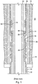
- Figure 1 depicts an ELH in accordance with the prior art.
- a wellbore 10 may be drilled through earth formation 12.
- a casing 14 may then be placed in an upper portion 16 of the well 10 and held in place by cement 18 which is injected between the casing 14 and the upper portion 16 of well 10.
- a lower portion 20 of the wellbore 10 may be drilled through casing 14, The lower portion 20 may have a smaller diameter than the upper portion 16.
- a length of liner 22 is shown positioned within the lower portion 20.
- the liner 22 may be used to line or case the lower portion 20 and/or to drill the lower portion 20.
- cement may be placed between the liner 22 and lower portion 20 of wellbore 10.
- the liner 22 may be installed in the wellbore 10 by means of a work string 24.
- the work string 24 may include a releasable collet, not shown, by which it can support and rotate the liner 22 as it is placed in the wellbore 10.
- a liner hanger 26 Attached to the upper end of, or formed as an integral part of, liner 22 is a liner hanger 26 which may include a number of annular seals 28. While three seals 28 are depicted for illustrative purposes, any number of seals 28 may be used.
- a polished bore receptacle, or tie back receptacle, 30 may be coupled to the upper end of the liner hanger 26. In one embodiment, the polished bore receptacle 30 may be coupled to the liner hanger 26 by a threaded joint 32, but in other embodiments a different coupling mechanism may be employed.
- the inner bore of the polished bore receptacle 30 may be smooth and machined to close tolerance to permit work strings, production tubing, etc.
- a work string may be connected by means of the polished bore receptacle 30 and used to pump fracturing fluid at high pressure down to the lower portion 20 of the wellbore 10 without exposing the casing 14 to the fracturing pressure.
- the outer diameter of liner 22 be as large as possible while being able to lower the liner 22 through the casing 14. It is also desirable that the outer diameter of the polished bore receptacle 30 and the liner hanger 26 be about the same as the diameter of liner 22.
- the outer diameter of liner hanger 26 is defined by the outer diameter of the annular seals 28.
- a body or mandrel 34 of liner hanger 26 has an outer diameter reduced by about the thickness of the seals 28 so that the outer diameter of the seals is about the same as the outer diameter of liner 22 and tie back receptacle 30.
- first and second expansion cones 36 and 38 may be carried on the work string 24 just above the reduced diameter body 34 of the liner hanger 26. Fluid pressure applied between the work string 24 and the liner hanger 26 may be used to drive the cones 36, 38 downward through the liner hanger 26 to expand the body 34 to an outer diameter at which the seals 28 are forced into sealing and supporting contact with the casing 14.
- the first expansion cone 36 may be a solid, or fixed diameter, cone having a fixed outer diameter smaller than the inner diameter 33 of the threaded joint 32.
- second expansion cone 38 may have an outer diameter greater than first cone 36 and also greater than the inner diameter 33 of the threaded joint 32.
- the second expansion cone 38 may be collapsible, that is, may be reduced in diameter smaller than the inner diameter 33 of the threaded joint 32 when it needs to be withdrawn from the liner hanger 26.
- the second expansion cone 38 may be referred to as a collapsible expansion cone.
- Typical seals 28 are made of elastomeric elements (e.g., rubber) which as discussed above may be susceptible to degradation as a result of exposure to the high temperatures and high pressures downhole.
- the seals 28 may be replaced with one or more metallic spikes.
- Figure 2 depicts a cross-sectional view of a system, including an improved liner hanger 26' where spikes 202 in accordance with an illustrative embodiment of the present disclosure have replaced the seals 28.
- the spikes 202 may be metal spikes.
- the metal spikes may be made of any suitable steel grade, Aluminum, any other ductile material, and a combination thereof. In certain implementations, the spikes may be made from a combination of one or more of the recited materials.
- the spikes 202 may be made from AISI4140 steel or AISI4340 steel.
- each spike 202 may be a circular ring that extends along an outer perimeter of the liner hanger 26' at a desired axial location.
- the present disclosure is not limited to this particular configuration of spikes 202.
- the spikes 202 may extend along an axial direction of the liner hanger 26'.
- the different spikes 202 may have different surface geometries without departing from the scope of the present disclosure.
- a first spike may extend along an outer perimeter of the liner hanger 26' at a first axial position along the liner hanger 26' and a second spike may extend along an outer perimeter of the liner hanger 26' at a second axial position along the liner hanger 26'.
- the spikes 202 may be formed using any suitable methods known to those of ordinary skill in the art.
- the spikes 202 may be formed by machining the hanger body 26'.
- the present disclosure it not limited to machined spikes.
- any suitable methods known to one of ordinary skill in the art may be used to form the spikes 202.
- the spikes 202 may be formed as a separate structure that can be coupled to the liner hanger 26' using any suitable coupling mechanisms known to one of ordinary skill in the art.
- any number of spikes 202 may be formed along the axial direction of the liner hanger 26'. The number of spikes 202 formed along the axial direction of the liner hanger 26' may depend upon a number of factors such as, for example, the anchor load that is desired to be reached.
- each of the spikes 202 provide a metal-to-metal seal between the liner hanger 26' and the casing 14.
- the spikes 202 may have a flat top portion 204.
- the use of spikes 202 with a flat top portion 204 as opposed to pointed spikes or threads is beneficial because flat spikes 202 are less sensitive to casing variations and have a higher load capacity than pointed spikes.
- the spikes 202 may be symmetrically aligned such that an angle ⁇ is the same on both sides of each spike 202 as shown in Figure 2 . However, in certain implementations, the angle ⁇ may be different on the opposing sides of the spike 202 without departing from the scope of the present disclosure.
- the angle ⁇ is referred to herein as the "spike angle.”
- the spike angle ( ⁇ ) is selected such that after expansion, the spikes 202 remain substantially normal to the liner hanger 26' body.
- the spike angle ( ⁇ ) may be selected to be in a range of from approximately 30° to approximately 70°.
- the dimension ⁇ denotes the width of the flat portion 204 of the spike 202 and is referred to herein as the spike width ( ⁇ ).
- the spike width ( ⁇ ) may be selected as desired such that the liner hanger 26' can expand without significant increase in expansion pressure while maintaining optimum contact area between the spikes 202 and the casing 14.
- the flat portion 204 of the spike interfaces with the inner surface of the casing 14 and will eventually couple the liner hanger 26' to the casing 14.
- the spikes 202 may be extended using one or more expansion cones in a manner similar to that disclosed in conjunction with expanding the seals 28 of Figure 1 .
- the spacing between the spikes 202 along the length of the liner hanger 26' is denoted as "L".
- the distance between the spikes (L) may be configured such that the deformation zones in the casing 14 induced by the spikes 202 are isolated.
- the distance (L) may be selected to maximize the hanging capacity per spike.
- hanging capacity refers to the maximum downward load (anchor load) a hanger can carry without inducing an appreciable relative motion between the hanger 26' and the casing 14 after the hanger is set in the casing. Accordingly, in certain implementations, it may not be desirable for the distance between the spikes (L) to fall below a certain threshold value.
- the distance between the spikes (L) may not be desirable for the distance between the spikes (L) to be less than three times the thickness of the casing 14. Accordingly, the distance (L) between the spikes 202 has an optimum value which is dependent upon a number of factors including, but not limited to, the outer diameter of the hanger (hanger OD), the hanger wall thickness, the inner diameter of the casing (casing ID) and the casing wall thickness. Moreover, the available length of the liner hanger 26' may limit the number of spikes 202 that may be placed thereon. Beyond this optimum value an increase in the distance (L) will no longer improve the hanging capacity per spike.
- the height (H) of the spikes 202 may be configured to have dimensions similar to the seals 28.
- the height (H) of the spike (also referred to herein as "spike height”) must be selected so that it is between an upper and a lower boundary.
- the upper spike height boundary may be selected as a function of the amount of flow area that is desired around the liner hanger 26' and the amount of possible rubber compression between the liner hanger 26' and the casing 14.
- the lower spike height boundary may be selected as a function of the amount of rubber compression desired between the liner hanger 26' and the casing 14.
- the spike height may destroy downhole equipment as it expands and if the spike height is too low, it wouldn't be able to support a liner as required. Configuration of the height (H) may cause a significant deformation of the spikes 202 and an appreciable localized plastic deformation of the casing.
- the spikes 202 of the liner hanger 26' are expanded, the spikes 202 and the inner diameter of the casing 14 form multiple metal-to-metal seals.
- the liner hanger 26' is coupled to the liner 22. Accordingly, the spikes 202 of the liner hanger 26' provide mechanical support for the liner 22.
- FIG 3 depicts a partial cross-sectional view of a liner hanger 26" having spikes 302 in accordance with another implementation of the present disclosure.
- the spikes 302 may be configured in the same manner discussed above in conjunction with Figure 2 .
- the spikes 302 may be metal spikes.
- each spike 302 may be a circular ring that extends along an outer perimeter of the liner hanger 26".
- the spikes 302 may be formed using any suitable methods known to those of ordinary skill in the art. For instance, in certain implementations, the spikes 302 may be formed by machining the hanger body 26". Moreover, any number of spikes 302 may be formed along the axial direction of the liner hanger 26".
- each of the spikes 302 formed along the axial direction of the liner hanger 26" may depend upon a number of factors such as, for example, the anchor load that is desired to be reached. Accordingly, each of the spikes 302 may provide a metal-to-metal seal between the liner hanger 26" and the casing 14.
- a sealing element may be positioned at a desired location and utilized in conjunction with the spikes 302.
- a sealing element 304 may be placed at an axial position on the liner hanger 26" above and/or below the spikes 302.
- the axial section of the liner hanger that contains the spikes 302 may be referred to herein as the "spiked portion.”
- a first sealing element 304A and a second sealing element 304B are positioned at distal ends of the spiked portion.
- the placement of a sealing element at one or both of the distal ends of the spiked portion of the liner hanger 26" may provide redundancy and pressure integrity for the system. This redundancy may be particularly beneficial in instances when one or more of the leading spikes 302 are damaged when the liner hanger 26" is being directed downhole.
- the sealing element 304 may be made of any suitable material, including, but not limited to, rubber, extremely ductile metals (e.g., AISI type 316L stainless steel), other polymeric materials, or any other pliable material known to those of ordinary skill in the art. With the liner hanger spikes 302 in an expanded position, the sealing element 304 reinforces the seal between the liner 22 and the casing 14.
- the implementation of Figure 3 may be particularly beneficial in instances when installed in a large size casing or a galled casing inner diameter having a pronounced inner diameter weld seam.
- sealing element 304 may be positioned at any desired location along the liner hanger 26". For instance, one sealing element 304 may be positioned at an axial position on the liner hanger 26" uphole relative to the spiked portion and/or one sealing element 304 may be positioned at an axial position on the liner hanger 26" downhole relative to the spiked portion. In certain implementations, the sealing element 304 may be positioned such that there are equal number of spikes 302 provided uphole and downhole relative to the sealing element 304.
- the metallic spikes 202, 302 of the improved liner hanger system (26' or 26") are much less susceptible to degradation than the traditional elastomeric seals 28 when exposed to high temperatures and/or pressures downhole. Moreover, the flat portion of the spikes 202, 302 minimizes the sensitivity of the liner hanger (26' or 26") to variations for a given weight casing. Accordingly, the improved liner hanger (26' or 26") provides several advantages. Not only does it provide an improved anchor load carrying capacity, it reduces the costs associated with performing operations using a liner hanger. Specifically, the use of metallic spikes instead of elastomeric seals 28 reduces the need for replacement of elastomeric elements 28 necessitated by performance of subterranean operations in HTHP environments downhole.
- the improved liner hanger (26' or 26") reduces the possibility of extruding long elastomers beyond the standard retainer spikes during expansion of the ELH. Specifically, as the liner hanger 26" expands, the spikes 302 and the sealing element 304 are also moved until they touch an Inner Diameter "ID" of the casing 14. As the expansion of the liner hanger 26" continues, the sealing element 304 is compressed along an axis of the liner hanger 26" and stretched along the perimeter of the liner hanger 26" due to pressure applied to it by the liner hanger 26", the inner wall of the casing 14 and the spikes 302 located at its two opposing lateral ends.
- the sealing element 304 As the sealing element 304 is compressed, it will eventually spill over the spikes 302 located at its lateral ends. However, as the spikes 302 are also pushed out by the liner hanger 26", they cut off the spilled portion of the sealing element 304 and the new compressed volume of the sealing element is trapped between the liner hanger 26" and the casing 14.
- the use of expandable spikes (202, 302) in the liner hanger (26' or 26") is advantageous over using traditional mechanical mechanisms such as, for example, a gauge hanger.
- the expandable spikes provide a simple, single-part mechanism that forms a reliable and robust seal between the casing and the liner and supports the liner.
- the use of spikes (202, 302) provides a robust seal in applications where the inner diameter of the casing 14 is imperfect.
- a casing may be lowered into the wellbore and cemented in place.
- a liner coupled to a liner hanger in accordance with an implementation of the present disclosure may then be lowered downhole through a casing. Once the liner reaches a desired position downhole, the metal spikes extending along the perimeter of the liner hanger expand. Once the metal hangers are expanded, the flat portion of the spikes forms a metal-to-metal seal with an inner surface of the casing. This metal-to-metal seal couples the liner to the casing.
Landscapes
- Geology (AREA)
- Life Sciences & Earth Sciences (AREA)
- Engineering & Computer Science (AREA)
- Mining & Mineral Resources (AREA)
- Geochemistry & Mineralogy (AREA)
- Fluid Mechanics (AREA)
- Environmental & Geological Engineering (AREA)
- General Life Sciences & Earth Sciences (AREA)
- Physics & Mathematics (AREA)
- Earth Drilling (AREA)
- Holders For Apparel And Elements Relating To Apparel (AREA)
- Gasket Seals (AREA)
- Branch Pipes, Bends, And The Like (AREA)
- Road Paving Structures (AREA)
- Chain Conveyers (AREA)
- Sealing Devices (AREA)
Claims (12)
- Système pour effectuer des opérations souterraines comprenant :une suspension de colonne perdue (26') positionnée à l'intérieur d'un logement (14),dans lequel la suspension de colonne perdue comprend une partie à pointes ayant une ou plusieurs pointes métalliques (202), chacune des une ou plusieurs pointes métalliques s'étendant dans un anneau circulaire le long d'un périmètre externe de la suspension de colonne perdue (26') ; dans lequel les une ou plusieurs pointes métalliques (202) sont effilées en une partie plate (204),dans lequel au moins l'une des une ou plusieurs pointes métalliques (202) est extensible, etdans lequel la partie plate (204) de chacune des une ou plusieurs pointes métalliques déforme le logement (14) lorsque la pointe est dans la position déployée,dans lequel chacune des une ou plusieurs pointes métalliques (202) fournit un joint métal sur métal entre la suspension de colonne perdue (26') et le logement (14) lorsque la pointe (202) est dans la position déployée ; etune colonne perdue (22) couplée à la suspension de colonne perdue (26') .
- Système selon la revendication 1, dans lequel les une ou plusieurs pointes (202)(i) sont fabriquées à partir d'un matériau choisi dans un groupe constitué d'aluminium, d'acier et d'une combinaison de ceux-ci ; ou(ii) comprennent une première pointe positionnée au niveau d'un premier emplacement axial le long de la suspension de colonne perdue et une seconde pointe positionnée au niveau d'un second emplacement axial le long de la suspension de colonne perdue.
- Système selon la revendication 1, dans lequel le déploiement des une ou plusieurs pointes (202) couple la suspension de colonne perdue (26') au logement (14).
- Système selon la revendication 1, dans lequel un angle de pointe d'une ou de plusieurs pointes métalliques est choisi de sorte que la pointe est sensiblement perpendiculaire à la suspension de colonne perdue lorsque la pointe est dans la position déployée.
- Système selon la revendication 1, comprenant en outre un élément d'étanchéité (304), dans lequel l'élément d'étanchéité est positionné au niveau d'une extrémité distale de la partie à pointes, de préférence dans lequel l'élément d'étanchéité est choisi dans un groupe constitué de caoutchouc, de matériaux polymères et de métaux ductiles.
- Système selon la revendication 1, dans lequel les une ou plusieurs pointes métalliques (202) ont un angle θ entre un côté de la pointe et une ligne perpendiculaire à la suspension de colonne perdue, et dans lequel l'angle θ est choisi pour se situer dans une plage de 30° à 70°.
- Procédé pour coupler une colonne perdue (22) à un logement (14) d'un puits de forage tubé dans une formation souterraine comprenant :le couplage d'une suspension de colonne perdue (26') à la colonne perdue (22),dans lequel la suspension de colonne perdue (26') comprend une partie à pointes ayant une première pointe métallique (202) comprenant une partie plate (204) ;l'abaissement de la colonne perdue (22) et de la suspension de colonne perdue (26') en fond de puits à travers le logement (14) ; etle déploiement de la première pointe (202), dans lequel la première pointe métallique entraîne une déformation du logement (14) et fournit un joint métal sur métal entre la suspension de colonne perdue (26') et le logement (14) lorsque la première pointe métallique est dans la position déployée, etdans lequel le déploiement de la première pointe couple la suspension de colonne perdue (26') au logement (14).
- Procédé selon la revendication 7, dans lequel un angle de pointe d'une ou de plusieurs pointes métalliques est choisi de sorte que la pointe est sensiblement perpendiculaire à la suspension de colonne perdue lorsque la pointe est dans la position déployée.
- Procédé selon la revendication 7, comprenant en outre un élément d'étanchéité (304), dans lequel l'élément d'étanchéité est positionné au niveau d'une extrémité distale de la partie à pointes.
- Procédé selon la revendication 7, dans lequel la partie à pointes comprend en outre une seconde pointe métallique s'étendant dans un anneau circulaire le long d'un périmètre externe de la suspension de colonne perdue, dans lequel la première pointe métallique est positionnée au niveau d'un premier emplacement axial le long de la suspension de colonne perdue (26') et la seconde pointe métallique est positionnée au niveau d'un second emplacement axial le long de la suspension de colonne perdue.
- Procédé selon la revendication 7, dans lequel la première pointe métallique est soit (i) formée par usinage, soit (ii) fabriquée à partir d'un matériau choisi dans un groupe constitué d'aluminium, d'acier et d'une combinaison de ceux-ci.
- Procédé selon la revendication 7, dans lequel les une ou plusieurs pointes métalliques (202) sont effilées en une partie plate (204).
Applications Claiming Priority (1)
| Application Number | Priority Date | Filing Date | Title |
|---|---|---|---|
| PCT/US2012/071171 WO2014098885A1 (fr) | 2012-12-21 | 2012-12-21 | Système de suspension de colonne perdue amélioré |
Publications (3)
| Publication Number | Publication Date |
|---|---|
| EP2935760A1 EP2935760A1 (fr) | 2015-10-28 |
| EP2935760A4 EP2935760A4 (fr) | 2016-11-23 |
| EP2935760B1 true EP2935760B1 (fr) | 2019-06-19 |
Family
ID=50978954
Family Applications (1)
| Application Number | Title | Priority Date | Filing Date |
|---|---|---|---|
| EP12890440.6A Active EP2935760B1 (fr) | 2012-12-21 | 2012-12-21 | Système de suspension de colonne perdue amélioré |
Country Status (9)
| Country | Link |
|---|---|
| EP (1) | EP2935760B1 (fr) |
| CN (1) | CN104797773B (fr) |
| AU (2) | AU2012397228A1 (fr) |
| BR (1) | BR112015012140B1 (fr) |
| CA (1) | CA2890607C (fr) |
| IN (1) | IN2015DN03851A (fr) |
| MX (1) | MX372898B (fr) |
| SG (1) | SG11201504211VA (fr) |
| WO (1) | WO2014098885A1 (fr) |
Families Citing this family (16)
| Publication number | Priority date | Publication date | Assignee | Title |
|---|---|---|---|---|
| CN107013180A (zh) * | 2017-06-02 | 2017-08-04 | 中国石油天然气集团公司 | 井筒可溶膨胀封堵装置 |
| WO2020046389A1 (fr) * | 2018-08-31 | 2020-03-05 | Halliburton Energy Services, Inc. | Suspension de colonne dotée de joints nano-renforcés |
| WO2020162986A1 (fr) * | 2019-02-05 | 2020-08-13 | Ducon - Becker Service Technology, Llc. | Système de colonne de production pour opérations de puits |
| GB2593614B (en) | 2019-02-22 | 2022-12-07 | Halliburton Energy Services Inc | An expanding metal sealant for use with multilateral completion systems |
| WO2021021203A1 (fr) | 2019-07-31 | 2021-02-04 | Halliburton Energy Services, Inc. | Procédés destinés à surveiller un produit d'étanchéité métallique déployé dans un puits de forage, procédés destinés à surveiller un déplacement de fluide, et systèmes de mesure de produit d'étanchéité métallique de fond de trou |
| US10961804B1 (en) | 2019-10-16 | 2021-03-30 | Halliburton Energy Services, Inc. | Washout prevention element for expandable metal sealing elements |
| US11519239B2 (en) | 2019-10-29 | 2022-12-06 | Halliburton Energy Services, Inc. | Running lines through expandable metal sealing elements |
| US12480373B2 (en) | 2019-11-13 | 2025-11-25 | Halliburton Energy Services, Inc. | Actuating a downhole device with a reactive metal |
| US11499399B2 (en) | 2019-12-18 | 2022-11-15 | Halliburton Energy Services, Inc. | Pressure reducing metal elements for liner hangers |
| US11761290B2 (en) | 2019-12-18 | 2023-09-19 | Halliburton Energy Services, Inc. | Reactive metal sealing elements for a liner hanger |
| US11761293B2 (en) | 2020-12-14 | 2023-09-19 | Halliburton Energy Services, Inc. | Swellable packer assemblies, downhole packer systems, and methods to seal a wellbore |
| US11572749B2 (en) * | 2020-12-16 | 2023-02-07 | Halliburton Energy Services, Inc. | Non-expanding liner hanger |
| US11578498B2 (en) | 2021-04-12 | 2023-02-14 | Halliburton Energy Services, Inc. | Expandable metal for anchoring posts |
| US11879304B2 (en) | 2021-05-17 | 2024-01-23 | Halliburton Energy Services, Inc. | Reactive metal for cement assurance |
| US12560360B2 (en) | 2022-11-01 | 2026-02-24 | Halliburton Energy Services, Inc. | Direct downhole electricity generation in a geothermal well |
| US12612843B2 (en) | 2023-12-26 | 2026-04-28 | Halliburton Energy Services, Inc. | Mechanical support for expandable liner hanger |
Citations (1)
| Publication number | Priority date | Publication date | Assignee | Title |
|---|---|---|---|---|
| US20020079106A1 (en) * | 1998-12-22 | 2002-06-27 | Simpson Neil Andrew Abercrombie | Procedures and equipment for profiling and jointing of pipes |
Family Cites Families (11)
| Publication number | Priority date | Publication date | Assignee | Title |
|---|---|---|---|---|
| US4311194A (en) * | 1979-08-20 | 1982-01-19 | Otis Engineering Corporation | Liner hanger and running and setting tool |
| US6648075B2 (en) * | 2001-07-13 | 2003-11-18 | Weatherford/Lamb, Inc. | Method and apparatus for expandable liner hanger with bypass |
| US6691789B2 (en) * | 2001-09-10 | 2004-02-17 | Weatherford/Lamb, Inc. | Expandable hanger and packer |
| US7441606B2 (en) * | 2003-05-01 | 2008-10-28 | Weatherford/Lamb, Inc. | Expandable fluted liner hanger and packer system |
| US7225880B2 (en) * | 2004-05-27 | 2007-06-05 | Tiw Corporation | Expandable liner hanger system and method |
| US7779910B2 (en) * | 2008-02-07 | 2010-08-24 | Halliburton Energy Services, Inc. | Expansion cone for expandable liner hanger |
| CN201284624Y (zh) * | 2008-09-01 | 2009-08-05 | 赵建军 | 不锈钢内衬管及连接组件 |
| US8443881B2 (en) * | 2008-10-13 | 2013-05-21 | Weatherford/Lamb, Inc. | Expandable liner hanger and method of use |
| US20100155084A1 (en) * | 2008-12-23 | 2010-06-24 | Halliburton Energy Services, Inc. | Setting tool for expandable liner hanger and associated methods |
| GB2474692B (en) * | 2009-10-23 | 2014-01-15 | Meta Downhole Ltd | Apparatus and method of connecting tubular members in a wellbore |
| US20120175846A1 (en) * | 2011-01-11 | 2012-07-12 | Baker Hughes Incorporated | Threaded device with metal to metal seal and method |
-
2012
- 2012-12-21 BR BR112015012140-3A patent/BR112015012140B1/pt active IP Right Grant
- 2012-12-21 WO PCT/US2012/071171 patent/WO2014098885A1/fr not_active Ceased
- 2012-12-21 SG SG11201504211VA patent/SG11201504211VA/en unknown
- 2012-12-21 CN CN201280077208.2A patent/CN104797773B/zh active Active
- 2012-12-21 EP EP12890440.6A patent/EP2935760B1/fr active Active
- 2012-12-21 IN IN3851DEN2015 patent/IN2015DN03851A/en unknown
- 2012-12-21 AU AU2012397228A patent/AU2012397228A1/en not_active Abandoned
- 2012-12-21 CA CA2890607A patent/CA2890607C/fr active Active
- 2012-12-21 MX MX2015006293A patent/MX372898B/es active IP Right Grant
-
2016
- 2016-12-08 AU AU2016269518A patent/AU2016269518B2/en active Active
Patent Citations (1)
| Publication number | Priority date | Publication date | Assignee | Title |
|---|---|---|---|---|
| US20020079106A1 (en) * | 1998-12-22 | 2002-06-27 | Simpson Neil Andrew Abercrombie | Procedures and equipment for profiling and jointing of pipes |
Also Published As
| Publication number | Publication date |
|---|---|
| WO2014098885A1 (fr) | 2014-06-26 |
| CA2890607A1 (fr) | 2014-06-26 |
| MX2015006293A (es) | 2015-11-06 |
| AU2012397228A1 (en) | 2015-05-28 |
| CA2890607C (fr) | 2017-08-01 |
| SG11201504211VA (en) | 2015-07-30 |
| EP2935760A4 (fr) | 2016-11-23 |
| BR112015012140B1 (pt) | 2021-03-09 |
| IN2015DN03851A (fr) | 2015-10-02 |
| AU2016269518B2 (en) | 2018-02-08 |
| CN104797773B (zh) | 2017-07-25 |
| AU2016269518A1 (en) | 2017-01-05 |
| MX372898B (es) | 2020-04-07 |
| BR112015012140A2 (pt) | 2017-07-11 |
| EP2935760A1 (fr) | 2015-10-28 |
| CN104797773A (zh) | 2015-07-22 |
Similar Documents
| Publication | Publication Date | Title |
|---|---|---|
| EP2935760B1 (fr) | Système de suspension de colonne perdue amélioré | |
| US9580981B2 (en) | Liner hanger system | |
| CA3121417C (fr) | Minimisation de l'impact d'un fluide piege sur des dispositifs de suspension de colonne perdue extensibles dans des applications geothermiques | |
| US9752400B2 (en) | Expandable liner hanger with high axial load capacity | |
| US12134956B2 (en) | Liner hanger system | |
| US20040007829A1 (en) | Downhole seal assembly and method for use of same | |
| NL2025580B1 (en) | Bias fabric reinforced elh element material for improved anchoring | |
| AU2004201822A1 (en) | Expandable Hanger with Compliant Slip System | |
| CA2968363C (fr) | Bague de prevention d'extrusion pour un systeme de suspension de colonne perdue | |
| WO2021202162A1 (fr) | Systèmes pour structures de suspension dans des environnements de fond de trou | |
| AU2015200546A1 (en) | Open hole expandable junction | |
| US11136864B2 (en) | Liner hanger with nano-reinforced seals | |
| US20200399976A1 (en) | Enhanced Elastomer Reinforcement for Expandable Hangers with Garter Spring | |
| CA2694822A1 (fr) | Procede pour modifier l'etat de contrainte d'une formation et/ou d'un element tubulaire |
Legal Events
| Date | Code | Title | Description |
|---|---|---|---|
| PUAI | Public reference made under article 153(3) epc to a published international application that has entered the european phase |
Free format text: ORIGINAL CODE: 0009012 |
|
| 17P | Request for examination filed |
Effective date: 20150605 |
|
| AK | Designated contracting states |
Kind code of ref document: A1 Designated state(s): AL AT BE BG CH CY CZ DE DK EE ES FI FR GB GR HR HU IE IS IT LI LT LU LV MC MK MT NL NO PL PT RO RS SE SI SK SM TR |
|
| AX | Request for extension of the european patent |
Extension state: BA ME |
|
| DAX | Request for extension of the european patent (deleted) | ||
| A4 | Supplementary search report drawn up and despatched |
Effective date: 20161021 |
|
| RIC1 | Information provided on ipc code assigned before grant |
Ipc: E21B 17/02 20060101ALI20161017BHEP Ipc: E21B 43/10 20060101ALI20161017BHEP Ipc: E21B 19/24 20060101AFI20161017BHEP |
|
| STAA | Information on the status of an ep patent application or granted ep patent |
Free format text: STATUS: EXAMINATION IS IN PROGRESS |
|
| 17Q | First examination report despatched |
Effective date: 20170918 |
|
| GRAP | Despatch of communication of intention to grant a patent |
Free format text: ORIGINAL CODE: EPIDOSNIGR1 |
|
| STAA | Information on the status of an ep patent application or granted ep patent |
Free format text: STATUS: GRANT OF PATENT IS INTENDED |
|
| INTG | Intention to grant announced |
Effective date: 20190107 |
|
| RIN1 | Information on inventor provided before grant (corrected) |
Inventor name: MOELLER, DANIEL KEITH Inventor name: ZHONG, XIAOGUANG ALLAN |
|
| GRAS | Grant fee paid |
Free format text: ORIGINAL CODE: EPIDOSNIGR3 |
|
| GRAA | (expected) grant |
Free format text: ORIGINAL CODE: 0009210 |
|
| STAA | Information on the status of an ep patent application or granted ep patent |
Free format text: STATUS: THE PATENT HAS BEEN GRANTED |
|
| AK | Designated contracting states |
Kind code of ref document: B1 Designated state(s): AL AT BE BG CH CY CZ DE DK EE ES FI FR GB GR HR HU IE IS IT LI LT LU LV MC MK MT NL NO PL PT RO RS SE SI SK SM TR |
|
| RAP1 | Party data changed (applicant data changed or rights of an application transferred) |
Owner name: HALLIBURTON ENERGY SERVICES INC. |
|
| REG | Reference to a national code |
Ref country code: GB Ref legal event code: FG4D |
|
| REG | Reference to a national code |
Ref country code: CH Ref legal event code: EP |
|
| REG | Reference to a national code |
Ref country code: IE Ref legal event code: FG4D |
|
| REG | Reference to a national code |
Ref country code: DE Ref legal event code: R096 Ref document number: 602012061313 Country of ref document: DE |
|
| REG | Reference to a national code |
Ref country code: AT Ref legal event code: REF Ref document number: 1145729 Country of ref document: AT Kind code of ref document: T Effective date: 20190715 |
|
| REG | Reference to a national code |
Ref country code: NO Ref legal event code: T2 Effective date: 20190619 |
|
| REG | Reference to a national code |
Ref country code: NL Ref legal event code: MP Effective date: 20190619 |
|
| PG25 | Lapsed in a contracting state [announced via postgrant information from national office to epo] |
Ref country code: HR Free format text: LAPSE BECAUSE OF FAILURE TO SUBMIT A TRANSLATION OF THE DESCRIPTION OR TO PAY THE FEE WITHIN THE PRESCRIBED TIME-LIMIT Effective date: 20190619 Ref country code: LT Free format text: LAPSE BECAUSE OF FAILURE TO SUBMIT A TRANSLATION OF THE DESCRIPTION OR TO PAY THE FEE WITHIN THE PRESCRIBED TIME-LIMIT Effective date: 20190619 Ref country code: SE Free format text: LAPSE BECAUSE OF FAILURE TO SUBMIT A TRANSLATION OF THE DESCRIPTION OR TO PAY THE FEE WITHIN THE PRESCRIBED TIME-LIMIT Effective date: 20190619 Ref country code: AL Free format text: LAPSE BECAUSE OF FAILURE TO SUBMIT A TRANSLATION OF THE DESCRIPTION OR TO PAY THE FEE WITHIN THE PRESCRIBED TIME-LIMIT Effective date: 20190619 Ref country code: FI Free format text: LAPSE BECAUSE OF FAILURE TO SUBMIT A TRANSLATION OF THE DESCRIPTION OR TO PAY THE FEE WITHIN THE PRESCRIBED TIME-LIMIT Effective date: 20190619 |
|
| REG | Reference to a national code |
Ref country code: LT Ref legal event code: MG4D |
|
| PG25 | Lapsed in a contracting state [announced via postgrant information from national office to epo] |
Ref country code: BG Free format text: LAPSE BECAUSE OF FAILURE TO SUBMIT A TRANSLATION OF THE DESCRIPTION OR TO PAY THE FEE WITHIN THE PRESCRIBED TIME-LIMIT Effective date: 20190919 Ref country code: RS Free format text: LAPSE BECAUSE OF FAILURE TO SUBMIT A TRANSLATION OF THE DESCRIPTION OR TO PAY THE FEE WITHIN THE PRESCRIBED TIME-LIMIT Effective date: 20190619 Ref country code: LV Free format text: LAPSE BECAUSE OF FAILURE TO SUBMIT A TRANSLATION OF THE DESCRIPTION OR TO PAY THE FEE WITHIN THE PRESCRIBED TIME-LIMIT Effective date: 20190619 Ref country code: GR Free format text: LAPSE BECAUSE OF FAILURE TO SUBMIT A TRANSLATION OF THE DESCRIPTION OR TO PAY THE FEE WITHIN THE PRESCRIBED TIME-LIMIT Effective date: 20190920 |
|
| REG | Reference to a national code |
Ref country code: AT Ref legal event code: MK05 Ref document number: 1145729 Country of ref document: AT Kind code of ref document: T Effective date: 20190619 |
|
| PG25 | Lapsed in a contracting state [announced via postgrant information from national office to epo] |
Ref country code: EE Free format text: LAPSE BECAUSE OF FAILURE TO SUBMIT A TRANSLATION OF THE DESCRIPTION OR TO PAY THE FEE WITHIN THE PRESCRIBED TIME-LIMIT Effective date: 20190619 Ref country code: PT Free format text: LAPSE BECAUSE OF FAILURE TO SUBMIT A TRANSLATION OF THE DESCRIPTION OR TO PAY THE FEE WITHIN THE PRESCRIBED TIME-LIMIT Effective date: 20191021 Ref country code: SK Free format text: LAPSE BECAUSE OF FAILURE TO SUBMIT A TRANSLATION OF THE DESCRIPTION OR TO PAY THE FEE WITHIN THE PRESCRIBED TIME-LIMIT Effective date: 20190619 Ref country code: CZ Free format text: LAPSE BECAUSE OF FAILURE TO SUBMIT A TRANSLATION OF THE DESCRIPTION OR TO PAY THE FEE WITHIN THE PRESCRIBED TIME-LIMIT Effective date: 20190619 Ref country code: RO Free format text: LAPSE BECAUSE OF FAILURE TO SUBMIT A TRANSLATION OF THE DESCRIPTION OR TO PAY THE FEE WITHIN THE PRESCRIBED TIME-LIMIT Effective date: 20190619 Ref country code: AT Free format text: LAPSE BECAUSE OF FAILURE TO SUBMIT A TRANSLATION OF THE DESCRIPTION OR TO PAY THE FEE WITHIN THE PRESCRIBED TIME-LIMIT Effective date: 20190619 Ref country code: NL Free format text: LAPSE BECAUSE OF FAILURE TO SUBMIT A TRANSLATION OF THE DESCRIPTION OR TO PAY THE FEE WITHIN THE PRESCRIBED TIME-LIMIT Effective date: 20190619 |
|
| PG25 | Lapsed in a contracting state [announced via postgrant information from national office to epo] |
Ref country code: SM Free format text: LAPSE BECAUSE OF FAILURE TO SUBMIT A TRANSLATION OF THE DESCRIPTION OR TO PAY THE FEE WITHIN THE PRESCRIBED TIME-LIMIT Effective date: 20190619 Ref country code: ES Free format text: LAPSE BECAUSE OF FAILURE TO SUBMIT A TRANSLATION OF THE DESCRIPTION OR TO PAY THE FEE WITHIN THE PRESCRIBED TIME-LIMIT Effective date: 20190619 Ref country code: IT Free format text: LAPSE BECAUSE OF FAILURE TO SUBMIT A TRANSLATION OF THE DESCRIPTION OR TO PAY THE FEE WITHIN THE PRESCRIBED TIME-LIMIT Effective date: 20190619 Ref country code: IS Free format text: LAPSE BECAUSE OF FAILURE TO SUBMIT A TRANSLATION OF THE DESCRIPTION OR TO PAY THE FEE WITHIN THE PRESCRIBED TIME-LIMIT Effective date: 20191019 |
|
| PG25 | Lapsed in a contracting state [announced via postgrant information from national office to epo] |
Ref country code: TR Free format text: LAPSE BECAUSE OF FAILURE TO SUBMIT A TRANSLATION OF THE DESCRIPTION OR TO PAY THE FEE WITHIN THE PRESCRIBED TIME-LIMIT Effective date: 20190619 |
|
| PG25 | Lapsed in a contracting state [announced via postgrant information from national office to epo] |
Ref country code: DK Free format text: LAPSE BECAUSE OF FAILURE TO SUBMIT A TRANSLATION OF THE DESCRIPTION OR TO PAY THE FEE WITHIN THE PRESCRIBED TIME-LIMIT Effective date: 20190619 Ref country code: PL Free format text: LAPSE BECAUSE OF FAILURE TO SUBMIT A TRANSLATION OF THE DESCRIPTION OR TO PAY THE FEE WITHIN THE PRESCRIBED TIME-LIMIT Effective date: 20190619 |
|
| PG25 | Lapsed in a contracting state [announced via postgrant information from national office to epo] |
Ref country code: IS Free format text: LAPSE BECAUSE OF FAILURE TO SUBMIT A TRANSLATION OF THE DESCRIPTION OR TO PAY THE FEE WITHIN THE PRESCRIBED TIME-LIMIT Effective date: 20200224 |
|
| REG | Reference to a national code |
Ref country code: DE Ref legal event code: R097 Ref document number: 602012061313 Country of ref document: DE |
|
| REG | Reference to a national code |
Ref country code: DE Ref legal event code: R119 Ref document number: 602012061313 Country of ref document: DE |
|
| PLBE | No opposition filed within time limit |
Free format text: ORIGINAL CODE: 0009261 |
|
| STAA | Information on the status of an ep patent application or granted ep patent |
Free format text: STATUS: NO OPPOSITION FILED WITHIN TIME LIMIT |
|
| PG2D | Information on lapse in contracting state deleted |
Ref country code: IS |
|
| REG | Reference to a national code |
Ref country code: CH Ref legal event code: PL |
|
| 26N | No opposition filed |
Effective date: 20200603 |
|
| REG | Reference to a national code |
Ref country code: BE Ref legal event code: MM Effective date: 20191231 |
|
| PG25 | Lapsed in a contracting state [announced via postgrant information from national office to epo] |
Ref country code: SI Free format text: LAPSE BECAUSE OF FAILURE TO SUBMIT A TRANSLATION OF THE DESCRIPTION OR TO PAY THE FEE WITHIN THE PRESCRIBED TIME-LIMIT Effective date: 20190619 Ref country code: MC Free format text: LAPSE BECAUSE OF FAILURE TO SUBMIT A TRANSLATION OF THE DESCRIPTION OR TO PAY THE FEE WITHIN THE PRESCRIBED TIME-LIMIT Effective date: 20190619 |
|
| PG25 | Lapsed in a contracting state [announced via postgrant information from national office to epo] |
Ref country code: LU Free format text: LAPSE BECAUSE OF NON-PAYMENT OF DUE FEES Effective date: 20191221 Ref country code: IE Free format text: LAPSE BECAUSE OF NON-PAYMENT OF DUE FEES Effective date: 20191221 Ref country code: DE Free format text: LAPSE BECAUSE OF NON-PAYMENT OF DUE FEES Effective date: 20200701 Ref country code: FR Free format text: LAPSE BECAUSE OF NON-PAYMENT OF DUE FEES Effective date: 20191231 |
|
| PG25 | Lapsed in a contracting state [announced via postgrant information from national office to epo] |
Ref country code: LI Free format text: LAPSE BECAUSE OF NON-PAYMENT OF DUE FEES Effective date: 20191231 Ref country code: CH Free format text: LAPSE BECAUSE OF NON-PAYMENT OF DUE FEES Effective date: 20191231 Ref country code: BE Free format text: LAPSE BECAUSE OF NON-PAYMENT OF DUE FEES Effective date: 20191231 |
|
| PG25 | Lapsed in a contracting state [announced via postgrant information from national office to epo] |
Ref country code: CY Free format text: LAPSE BECAUSE OF FAILURE TO SUBMIT A TRANSLATION OF THE DESCRIPTION OR TO PAY THE FEE WITHIN THE PRESCRIBED TIME-LIMIT Effective date: 20190619 |
|
| PG25 | Lapsed in a contracting state [announced via postgrant information from national office to epo] |
Ref country code: MT Free format text: LAPSE BECAUSE OF FAILURE TO SUBMIT A TRANSLATION OF THE DESCRIPTION OR TO PAY THE FEE WITHIN THE PRESCRIBED TIME-LIMIT Effective date: 20190619 Ref country code: HU Free format text: LAPSE BECAUSE OF FAILURE TO SUBMIT A TRANSLATION OF THE DESCRIPTION OR TO PAY THE FEE WITHIN THE PRESCRIBED TIME-LIMIT; INVALID AB INITIO Effective date: 20121221 |
|
| PG25 | Lapsed in a contracting state [announced via postgrant information from national office to epo] |
Ref country code: MK Free format text: LAPSE BECAUSE OF FAILURE TO SUBMIT A TRANSLATION OF THE DESCRIPTION OR TO PAY THE FEE WITHIN THE PRESCRIBED TIME-LIMIT Effective date: 20190619 |
|
| PGFP | Annual fee paid to national office [announced via postgrant information from national office to epo] |
Ref country code: GB Payment date: 20251103 Year of fee payment: 14 |
|
| PGFP | Annual fee paid to national office [announced via postgrant information from national office to epo] |
Ref country code: NO Payment date: 20251121 Year of fee payment: 14 |