EP2935895B1 - Technique optimisée pour activer et désactiver des pompes dans un système de pompes multiples - Google Patents
Technique optimisée pour activer et désactiver des pompes dans un système de pompes multiples Download PDFInfo
- Publication number
- EP2935895B1 EP2935895B1 EP13829054.9A EP13829054A EP2935895B1 EP 2935895 B1 EP2935895 B1 EP 2935895B1 EP 13829054 A EP13829054 A EP 13829054A EP 2935895 B1 EP2935895 B1 EP 2935895B1
- Authority
- EP
- European Patent Office
- Prior art keywords
- pump
- signal processor
- processing module
- specific energy
- lag
- Prior art date
- Legal status (The legal status is an assumption and is not a legal conclusion. Google has not performed a legal analysis and makes no representation as to the accuracy of the status listed.)
- Active
Links
Images

Classifications
-
- G—PHYSICS
- G05—CONTROLLING; REGULATING
- G05D—SYSTEMS FOR CONTROLLING OR REGULATING NON-ELECTRIC VARIABLES
- G05D7/00—Control of flow
- G05D7/06—Control of flow characterised by the use of electric means
-
- F—MECHANICAL ENGINEERING; LIGHTING; HEATING; WEAPONS; BLASTING
- F04—POSITIVE - DISPLACEMENT MACHINES FOR LIQUIDS; PUMPS FOR LIQUIDS OR ELASTIC FLUIDS
- F04D—NON-POSITIVE-DISPLACEMENT PUMPS
- F04D15/00—Control, e.g. regulation, of pumps, pumping installations or systems
- F04D15/0066—Control, e.g. regulation, of pumps, pumping installations or systems by changing the speed, e.g. of the driving engine
-
- F—MECHANICAL ENGINEERING; LIGHTING; HEATING; WEAPONS; BLASTING
- F04—POSITIVE - DISPLACEMENT MACHINES FOR LIQUIDS; PUMPS FOR LIQUIDS OR ELASTIC FLUIDS
- F04D—NON-POSITIVE-DISPLACEMENT PUMPS
- F04D15/00—Control, e.g. regulation, of pumps, pumping installations or systems
- F04D15/02—Stopping of pumps, or operating valves, on occurrence of unwanted conditions
- F04D15/0245—Stopping of pumps, or operating valves, on occurrence of unwanted conditions responsive to a condition of the pump
- F04D15/0254—Stopping of pumps, or operating valves, on occurrence of unwanted conditions responsive to a condition of the pump the condition being speed or load
-
- F—MECHANICAL ENGINEERING; LIGHTING; HEATING; WEAPONS; BLASTING
- F04—POSITIVE - DISPLACEMENT MACHINES FOR LIQUIDS; PUMPS FOR LIQUIDS OR ELASTIC FLUIDS
- F04D—NON-POSITIVE-DISPLACEMENT PUMPS
- F04D15/00—Control, e.g. regulation, of pumps, pumping installations or systems
- F04D15/02—Stopping of pumps, or operating valves, on occurrence of unwanted conditions
- F04D15/029—Stopping of pumps, or operating valves, on occurrence of unwanted conditions for pumps operating in parallel
Definitions
- the present invention relates to a technique for controlling pumps in a multiple pump system; and more particularly relates to a technique for determining whether to stage or de-stage one or more pumps in the multiple pump system.
- variable frequency drive systems having multiple pumps will turn-on (stage) or turn-off (de-stage) based on the attainment of specific drive values and their relationship to the current process value.
- Typical drive values used are speed or torque but can also be values of current or power, if pumps are identical.
- This methodology utilizes the relationship between the actual process variable and the process variable set point and a designated drive value which must be met before determining if a pump should be staged or de-staged.
- Each pump in the multiple pump system has its own parameter settings for the stage and de-stage threshold values.
- US 5,742,500 A1 discloses a pump station control system having multiple pumps for monitoring e.g. using a time history of sensed operating parameters and calculated real-time costs parameters of the system that provides a measure of the costs per throughput of the material being pumped.
- the pump station control system adjust the speed of a pump based upon a real time cost parameter.
- US 4,805,118 A1 discloses a method and apparatus for monitoring and controlling a multi-pump system wherein wire-te-water efficiency is accurately determined dependent on the flow through the system, the total dynamic head across the inlet and outlet headers of the system, the energy input to the system to drive the pump and a predetermined conversion factor.
- the pumps of the system are selectively energized and deenergized as the efficiency varies above and/or below efficiency setpoints so as to optimize the efficiency of the pumping system.
- US Patent No. 8,328,523 entitled “Synchronous Torque Balance in Multiple Pump Systems,” assigned to the assignee of the instant patent application, discloses a method and apparatus for operating and running multiple pumps together in a system using synchronous torque to achieve a desired set point.
- shortcomings of the above mentioned devices may include the following:
- the setup of variable frequency drive systems having multiple pumps as described in above referenced techniques may be both cumbersome and time consuming. It may also be difficult to determine the appropriate de-stage values without trial and error particularly in systems where load balancing (synchronous torque control) is important or where pumps do not have matched performance. This may result in pumps not turning on or off as required. It can also result in cycling whereby a pump frequently turns off and then back on again due to incorrect threshold values. Additionally, this methodology does not address energy efficiency. If the operating number of pumps is not optimum it will result in higher operating cost.
- VFD variable speed drives
- PLC programmable logic controllers
- DCS distributive control systems
- SCADA SCADA systems proliferate in centrifugal pump processes.
- multiple pumps operate in a coordinated fashion to satisfy a set point.
- VFD variable speed drives
- PLC programmable logic controllers
- DCS distributive control systems
- SCADA SCADA systems proliferate in centrifugal pump processes.
- multiple pumps operate in a coordinated fashion to satisfy a set point.
- VLC programmable logic controllers
- DCS distributive control systems
- SCADA SCADA systems
- shortcomings of these further mentioned devices may include the following: While both of these systems have been successfully employed; both arrangements have similar shortcomings.
- the setup of these systems is cumbersome and time consuming. Quite often de-stage values are determined through trial and error during commissioning of the system. It is essential to have the correct threshold values to stage or de-stage a pump to prevent premature staging and de-staging or cycling whereby pumps are prematurely turning on and off. Extreme cases could result in a decrease of system reliability and unscheduled maintenance of the equipment.
- the costs associated with unscheduled maintenance include the repair of equipment, interruptions in production and costs associated with environmental cleanup. Incorrect threshold values also increase operating cost over the life of the system.
- the typical multiple pump system has parameters for stage values for each pump.
- the stage values dictate the required speed that the lead pump must be at before multiple pump operation is allowed by the first lag pump.
- the multiple pump system will automatically start a lag pump when it is unable to maintain the process set point with the current pumps operating providing the speed or torque value is at or above the stage setting.
- Each pump in the multiple pump system has a parameter for a de-stage value.
- the de-stage parameters identify when pumps are turned off in normal multiple pump control. The primary consideration is to insure that when a lag pump is shutdown the remaining pumps are capable of meeting the process demand.
- the de-stage setting defines how much of a speed decrease or torque decrease can occur before a pump can be de-staged.
- the methodology provided by the present invention does this by utilizing variable speed drives with embedded control logic or algorithms to optimize the staging and de-staging of pumps in a multiple pump system without the use of additional external inputs.
- the present invention overcomes the aforementioned shortcomings of the prior art systems by basing the decision as to whether a pump should be staged or de-staged on an evaluation of specific energy for multiple pump combinations along with certain other criteria which must be met such as the current PV value, pump flow and pump power.
- Specific energy is a measure of energy used per unit mass.
- the staging methodology determines the specific energy of the current pumps that are running and the effect on total system specific energy of adding another pump to meet the process demand. The process variable must be met before a pump combination has its specific energy contribution calculated. A comparison can then be made between the two calculated values of system specific energy; the pump combination having the lesser value is chosen for staging. Pump combinations where individual pump flow is greater than a pre-selected value are not considered for selection.
- any pump in the combination being evaluated having a power value which exceeds the nameplate motor rating multiplied by a pre-selected service factor and/or a flow value which exceeds a predetermined BEP Limit Ratio will not be considered for selection. If either of these cases occurs an additional pump will automatically be staged prior to calculating the system specific energy.
- the de-staging methodology works similarly but in reverse with the same basic rules applying. The benefits of this method or technique are that the system setup is simpler, quicker, more reliable and optimized for energy efficiency. The energy optimization is highly accurate and the pumps do not need to have closely matched performance. Although flow is a criterion in specific energy the methodology can still be used if a flow value (actual or calculated) is unavailable.
- the present invention may include, or take the form of, apparatus featuring a signal processor or processing module configured at least to:
- the present invention may also include one or more of the following features:
- the signal processor or processing module may be configured to provide corresponding signaling containing information about whether to stage or de-stage the pump in the multiple pump system.
- the signaling may be received from one or more pumps in a multiple pump system.
- the apparatus may include the one or more pumps in a multiple pump system.
- the signal processor or processing module may be configured to implement control logic or a control logic algorithm based at least partly on the system energy consumption taking the form of specific energy that is a measure of energy used per unit mass for the multiple pump combinations running in the multiple pump system.
- the signal processor or processing module may be configured to determine the specific energy of current pumps running and an effect on a total system specific energy of adding another pump to meet process demands related to the multiple pump system.
- the signal processor or processing module may be configured in a first case to make a comparison between two calculated values of system specific energy; and to choose a pump combination either having a lesser value for staging, or having a greater value for de-staging.
- the signal processor or processing module may be configured in a second case to evaluate and not consider for selection any pump in a pump combination having a power value which exceeds a nameplate motor rating multiplied by a pre-selected service factor and/or a flow value which exceeds a predetermined BEP Limit Ratio.
- the signal processor or processing module may be configured to stage automatically an additional pump if either case occurs prior to calculating the system specific energy.
- the signal processor or processing module may be configured as, or forms part of, at least one variable speed drive with embedded control logic to optimize the staging or de-staging of pumps in the multiple pump system, including with the use of additional external inputs.
- the signal processor or processing module may be configured with control logic or a control logic algorithm that utilizes calculated flow data that is mathematically determined from various pump and motor parameters, including speed, torque or power or from calibrated flow curves stored in an evaluation device.
- the signal processor or processing module may be configured with control logic or a control logic algorithm that uses any drive parameter that has a direct relationship to pump flow.
- the signal processor or processing module is configured to implement control logic or a control logic algorithm based at least partly on the system energy consumption taking the form of relative measures of pumping efficiency, including flow economy which is substantially equal to flow/wire-water power or total system wire-water power, if a flow value is unavailable.
- the signal processor or processing module may be configured with control logic or a control logic algorithm in order to implement optimized staging of one or more pumps in the multiple pump system, consistent with that set forth herein, and as follows:
- Q Q CALC or Q AVG , in which Q CALC is a calculated Flow for pump n, Q AVG is an average pump flow, and Q AVG being Q FM /n for Q FM is the flow meter reading and n is the number of pumps running;
- Q BEP is a Best Efficiency Flow at a rated pump speed;
- N ACT is an Actual Pump Speed;
- N RTD is a
- the signal processor or processing module may be configured to determine an optimum number of pumps which should run for the operating condition, and make a comparison between SE TOTAL2 , for the lead pump and the first lag pump running, and SE TOTAL1 for the lead pump only running, based at least partly on: SE TOTAL 2 ⁇ SE TOTAL 1 , where
- the signal processor or processing module may be configured to determine when the multiple pump system is operating in a second condition, if either:
- the signal processor or processing module may be configured to determine when the multiple pump system is operating in the second condition, and also determine not to calculate an SE value when the lead pump only is running.
- the signal processor or processing module may be configured to determine an optimum number of pumps which should run for the operating condition, and make a comparison between SE TOTAL3 , for the lead pump, the first lag pump and the second lag pump running, and SE TOTAL2 for the lead pump and the first lag pump running, based at least partly on: SE TOTAL 3 ⁇ SE TOTAL 2 , where
- the signal processor or processing module may be configured with control logic or a control logic algorithm in order to implement optimized de-staging of one or more pumps in the multiple pump system, consistent with that set forth herein, and as follows:
- the signal processor or processing module may be configured to determine an optimum number of pumps which should run for the operating condition, and make a comparison between SE TOTALn , for the pumps 1 to n running, and SE TOTALn-1 for the n-1 pumps only running, based at least partly on : SE TOTALn ⁇ SE TOTALn ⁇ 1 , where
- the signal processor or processing module may be configured to determine in the second operating condition an optimum number of pumps which should run for the operating condition, and make a comparison between SE TOTALn-1 for the pumps 1 to n-1 running and SE TOTALn-2 for the pumps 1 to n-2 running, based at least partly on the following: SE TOTALn ⁇ 1 ⁇ SE TOTALn ⁇ 2 where
- the signal processor or processing module may be configured to determine in a third operating condition if the set point is not being met with all available pumps running, and if so, then de-staging a lag pump is not an option.
- the present invention may include, or take the form of, a method featuring steps for receiving in a signal processor or processing module signaling containing information about system energy consumption related to multiple pump combinations running in a multiple pump system; and determining in the signal processor or processing module whether to stage or de-stage a pump in the multiple pump system, based at least partly on the signaling received.
- the method may include a step for providing with the signal processor or processing module corresponding signaling containing information about whether to stage or de-stage the pump in the multiple pump system, as well as steps for implementing one or more of the other features set forth herein.
- the apparatus 10 may include, or take the form of, a signal processor or processing module 10a for implementing signal processing functionality associated with the present invention.
- the signal processor or processing module 10a may be configured at least to:
- the apparatus 10 may include other circuits, components or modules 10b, e.g., arranged between the multiple pump system 12 and the signal processor or processing module 10a.
- the other circuits, components or modules 10b may be configured to cooperate with the signal processor or processing module 10a in order to implement the signal processing functionality of the signal processor or processing module 10a.
- the other circuits, components or modules 10b may include, e.g., memory modules, input/output modules, data and busing architecture and other signal processing circuits, wiring or components.
- an output module that forms part of the components or modules 10b may be configured to exchange the signaling S with the signal processor or processing module 10a.
- the signal processor or processing module 10a is arranged in relation to n pumps labeled 12a, 12b, 12c and 12d respectively, including pump1, pump2, pump3, ... and pumpn, in the multiple pump system 12.
- the components or modules 10b and the n pumps 12a, 12b, 12c and 12d may be configured to exchange associated signaling, e.g., having reference labels S 1 , S 2 , S 3 , ..., S n respectively as shown.
- the signaling S containing information about the system energy consumption related to the multiple pump combinations may form part of the associated signal S 1 , S 2 , S 3 , ..., S n exchanged.
- the signal processor or processing module 10a may be configured to provide corresponding signaling containing information about whether to stage or de-stage one or more of the n pumps 12a, 12b, 12c and 12d in the multiple pump system 12.
- the corresponding signaling provided may form part of the exchange of signaling S between the components or modules 10b and the signal processor or processing module 10a, as well as the signal exchange S 1 , S 2 , S 3 , ..., S n between the components or modules 10b and the n pumps 12a, 12b, 12c and 12d.
- the corresponding signaling is provided via either a hard wiring signal exchange and/or a wireless signal exchange.
- the apparatus 10 may include, or take the form of, e.g. the signal processor or processing module 10a alone or in combination with the components or modules 10b and/or the one or more n pumps 12a, 12b, 12c and 12d in the multiple pump system 12.
- the signal processor or processing module 10a may be configured with control logic or a control logic algorithm to implement signal processing functionality, as follows:
- the signal processor or processing module 10a may be configured to implement control logic or a control logic algorithm based at least partly on the system energy consumption taking the form of specific energy, e.g., that is a measure of energy used per unit mass for the multiple pump combinations running in the multiple pump system 12.
- the signal processor or processing module 10a may be configured to determine the specific energy of current pumps running and the effect on the total system specific energy of adding another pump to meet process demands related to the multiple pump system 12.
- the signal processor or processing module 10a may be configured in one case to make a comparison between two calculated values of system specific energy; and to choose a pump combination either having a lesser value for staging, or having a greater value for de-staging.
- the signal processor or processing module 10a may be configured in another case to evaluate and determine, e.g. not to consider for selection, any pump in a pump combination having a power value which exceeds a nameplate motor rating multiplied by a pre-selected service factor and/or a flow value which exceeds a predetermined BEP Limit Ratio.
- the signal processor or processing module 10a may be configured to stage automatically an additional pump, e.g., if either of the aforementioned cases occurs prior to calculating the system specific energy.
- the signal processor or processing module 10a may be configured as, or forms part of, at least one variable speed drive with embedded control logic or a control logic algorithm to optimize the staging or de-staging of pumps in the multiple pump system, e.g., including with the use of additional external inputs, such as from a flow meter.
- the signal processor or processing module 10a may be configured with control logic or a control logic algorithm that utilizes calculated flow data that is mathematically determined from various pump and motor parameters, including speed, torque or power or from calibrated flow curves, e.g., stored in an evaluation or memory device that may form part of the components or modules 10b.
- the signal processor or processing module 10a may be configured with control logic or a control logic algorithm that uses any drive parameter that has a direct relationship to pump flow, including but not limited to the drive parameter disclosed herein.
- control logic or a control logic algorithm that uses any drive parameter that has a direct relationship to pump flow, including but not limited to the drive parameter disclosed herein.
- the scope of the invention is also intended to include other drive parameters that are either now known in the art or later developed in the future.
- the signal processor or processing module 10a may be configured to implement control logic or a control logic algorithm based at least partly on the system energy consumption taking the form of one or more relative measures of pumping efficiency, e.g., including flow economy which is substantially equal to flow/wire-water power or total system wire-water power, if a flow value is unavailable.
- control logic or a control logic algorithm based at least partly on the system energy consumption taking the form of one or more relative measures of pumping efficiency, e.g., including flow economy which is substantially equal to flow/wire-water power or total system wire-water power, if a flow value is unavailable.
- the present invention may also include, or take the form of, a method featuring steps for receiving in the signal processor or processing module 10a signaling containing information about system energy consumption related to multiple pump combinations running in the multiple pump system 12; and determining in the signal processor or processing module 10a whether to stage or de-stage a pump in the multiple pump system 12, based at least partly on the signaling received, consistent with that disclosed herein, including that shown in the flow charts in Figures 1 and 2 and described below.
- Figures 12-23 Examples of Control Logic or Control Logic Algorithms for Implementing Staging or De-staging of One or More Pumps
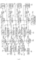
- Figures 1 and 2 show particular examples of flow charts having steps for implementing control logic or control logic algorithms for staging and de-staging of one or more pumps in a multiple pump system like element 12.
- control logic or a control logic algorithm associated with the present invention may be implemented, based at least partly on using parameters, variable frequency drive (VFD) signals and calculated values, as following:
- the parameters may include at least the following:
- the VFD signals may include at least the following:
- the calculated values may include at least the following:
- control logic or a control logic algorithm associated with the present invention may be implemented, based at least partly on the following:
- Figure 1 shows a flow chart having steps labeled 20a through 20t for implementing optimized staging, e.g., in a four pump system.
- the optimized staging process may begin as follows:
- the lead pump may be initially started either manually or by waking-up from a sleep condition after process demand has been re-established.
- PV ACT Set Point and Q/ (Q BEP x N ACT /N RTD ) ⁇ BEP Limit Ratio and P ACT ⁇ P RTD X SF, then the system may be determined to be operating normally.
- the term SF represents a motor service factor (normally 1.0) it also can be modified to suit the application.
- the equation P ACT ⁇ P RTD x SF is determined to be an indication as to whether the motor may be overloading.
- the signal processor or processing module 10a may be configured with a staging control logic or control logic algorithm that evaluates three conditions:
- SE TOTAL2 lead and lag running
- SE TOTAL1 lead only running
- the lag pump #1 may be staged, and the SE TOTAL2 may be calculated and saved once condition normal is determined to be reached.
- SE TOTAL3 lead, lag#1 and lag#2 running
- SE TOTAL2 lead and lag #1 running
- the SE evaluation may be performed again. In another embodiment these values can be adjusted as required.
- the scope of the invention is intended to include the above control logic for staging pumps applying to multiple pump systems having any number of pumps.
- the scope of the invention is intended to include implementations in multiple pump systems having more or less than 4 pumps.
- Figure 2 shows a flow chart having steps labeled 30a through 20z for implementing optimized de-staging, e.g., in a four pump system.
- the optimized de-staging process may begins as follows: By way of example, all four pumps are running and the set point may be lowered at least -5% or a system change occurs resulting in at least a -10% speed change. In another embodiment, these threshold values can be adjusted to suit the application.
- PV ACT Set Point and Q/ (Q BEP x N ACT /N RTD ) ⁇ BEP Limit Ratio and P ACT ⁇ P RTD X SF, the system is determined to be operating normally.
- the term SF represents a motor service factor (normally 1.0) it also can be modified to suit the application.
- the equation P ACT ⁇ P RTD x SF is determined to be an indication as to whether the motor may be overloading.
- the signal processor or processing module 10a may be configured with a de-staging control logic or control logic algorithm that evaluates four conditions:
- SE TOTAL4 lead, lags #1,#2 and #3 running
- SE TOTAL3 lead, lags #1 and #2 running
- SE TOTAL3 SE PMP 1 + SE PMP 2 + SE PMP 3
- SE TOTAL3 lead, lags #1 and #2 running
- SE TOTAL2 lead and #1 running
- condition 3 if condition 3 exists then an SE value is determined not to be calculated. If the set point is determined not to being met with all available pumps running; de-staging a pump is determined not to be an option. In other embodiments, the value of 0.98 can be adjusted as required.
- the SE evaluation is determined to be performed again. In another embodiment these values can be adjusted as required.
- the scope of the invention is intended to include the above control logic for de-staging pumps applying to multiple pump systems having any number of pumps.
- the scope of the invention is intended to include implementations in multiple pump systems having more or less than 4 pumps.
- the functionality of the signal processor 10a may be implemented with one or more modules using hardware, software, firmware, or a combination thereof.
- the one or more modules that form part of the signal processor 10a would include one or more microprocessor-based architectures having a microprocessor, a random access memory (RAM), a read only memory (ROM), input/output devices and control, data and address buses connecting the same.
- RAM random access memory
- ROM read only memory
- a person skilled in the art would appreciate and be able to program such a microprocessor-based implementation to perform the functionality described herein without undue experimentation.
- the scope of the invention is not intended to be limited to any particular implementation using some combination of hardware, software, or firmware technology either now known or later developed in the future.
- the Signal Processor 10a as a Chipset
- one or more modules of the signal processor 10a may also form part of a basic chipset implementation.
- the present invention may also take the form of the chipset that may include a number of integrated circuits designed to perform one or more related functions, including a chipset or chip formed as a group of integrated circuits, or chips, that are designed to work together.
- one chipset may provide the basic functions of the overall controller, while another chipset may provide control processing unit (CPU) functions for a computer or processor in overall controller.
- Newer chipsets generally include functions provided by two or more older chipsets. In some cases, older chipsets that required two or more physical chips can be replaced with a chipset on one chip.
- the term "chipset" is also intended to include the core functionality of a motherboard in such a controller.
- VFD variable speed drives
- PLC programmable logic controllers
- DCS distributive control systems
Landscapes
- Engineering & Computer Science (AREA)
- Mechanical Engineering (AREA)
- General Engineering & Computer Science (AREA)
- Physics & Mathematics (AREA)
- General Physics & Mathematics (AREA)
- Automation & Control Theory (AREA)
- Control Of Positive-Displacement Pumps (AREA)
- Control Of Non-Positive-Displacement Pumps (AREA)
Claims (11)
- Appareil (10) comprenant :
un processeur de signaux ou un module de traitement de signaux (10a) configuré au moins :pour recevoir des informations contenant une signalisation concernant une consommation d'énergie de système se rapportant à des combinaisons de pompes multiples fonctionnant dans un système à pompes multiples (12) ; etpour déterminer s'il convient d'activer ou de désactiver une pompe (12a, 12b, 12c, 12d) dans le système à pompes multiples (12) en se basant, au moins partiellement, sur la signalisation reçue etdans lequel le processeur de signaux ou le module de traitement de signaux (10a) est configuré avec une logique de commande ou un algorithme de logique de commande qui utilise des données de flux calculées qui sont déterminées mathématiquement à partir de divers paramètres de pompe et de moteur, comprenant la vitesse, le couple et la puissance, ou à partir de courbes de flux étalonnées stockées dans un dispositif d'évaluation,dans lequel le processeur de signaux ou le module de traitement de signaux (10a) est en outre configuré pour mettre en œuvre une logique de commande ou un algorithme de logique de commande en se basant, au moins partiellement, sur la consommation d'énergie de système qui prend la forme d'une énergie spécifique au système qui est une mesure de l'énergie utilisée par masse unitaire pour les combinaisons de pompes multiples fonctionnant dans le système à pompes multiples (12),et dans lequel le processeur de signaux ou le module de traitement de signaux (10a) est configuré pour déterminer l'énergie spécifique de pompes actuelles en fonctionnement et un effet sur une énergie totale spécifique au système d'ajout d'une autre pompe (12a, 12b, 12c, 12d) pour satisfaire à des demandes de processus se rapportant au système à pompes multiples (12),le processeur de signaux ou le module de traitement de signaux (10a) est configuré pour réaliser une comparaison entre deux valeurs calculées de l'énergie spécifique au système ; et pour choisir une combinaison de pompes soit ayant une valeur moindre pour une activation, soit ayant une valeur plus importante pour une désactivation ; caractérisé en ce que le processeur de signaux ou le module de traitement de signaux (10a) est configuré pour évaluer et pour ne pas prendre en considération une sélection de n'importe quelle pompe (12a, 12b, 12c, 12d) dans une combinaison de pompes ayant une valeur de puissance qui dépasse un régime moteur nominal multiplié par un facteur de service présélectionné et/ou une valeur de flux qui dépasse un rapport de limite de point BEP prédéterminé ; et le processeur de signaux ou le module de traitement de signaux (10a) est configuré pour activer automatiquement une pompe supplémentaire (12a, 12b, 12c, 12d) si l'un ou l'autre cas se produit avant de calculer l'énergie spécifique au système. - Appareil selon la revendication 1, dans lequel le processeur de signaux ou le module de traitement de signaux (10a) est configuré pour fournir des informations contenant une signalisation correspondante, indiquant s'il convient d'activer ou de désactiver la pompe (12a, 12b, 12c, 12d) dans le système à pompes multiples (12).
- Appareil selon la revendication 1, dans lequel le processeur de signaux ou le module de traitement de signaux (10a) est configuré sous la forme, ou forme une partie, d'au moins un entraînement à vitesse variable ayant une logique de commande intégrée pour optimiser l'activation ou la désactivation de pompes dans le système à pompes multiples (12), y compris avec l'utilisation d'entrées externes supplémentaires.
- Appareil selon la revendication 1, dans lequel le processeur de signaux ou le module de traitement de signaux (10a) est en outre configuré avec une logique de commande ou un algorithme de logique de commande qui utilise n'importe quel paramètre d'entraînement qui présente une relation directe avec un débit de pompe (Q).
- Appareil selon la revendication 1, dans lequel le processeur de signaux ou le module de traitement de signaux (10a) est en outre configuré pour mettre en œuvre une logique de commande ou un algorithme de logique de commande sur la base, au moins partiellement, sur la consommation d'énergie du système prenant la forme de mesures relatives de l'efficacité de pompage, y compris une économie de débit qui est sensiblement égale au débit (Q) divisé par un rendement global (PTw-w).
- Appareil selon la revendication 1, dans lequel le processeur de signaux ou le module de traitement de signaux (10a) est en outre configuré pour mettre en œuvre une logique de commande ou un algorithme de logique de commande et pour déterminer si le système à pompes multiples (12) fonctionne normalement, en se basant, au moins partiellement, sur au moins les trois conditions suivantes :


- Appareil selon la revendication 6, dans lequel le processeur de signaux ou le module de traitement de signaux (10a) est configuré pour déterminer lorsque le système à pompes multiples (12) fonctionne dans une condition normale et pour calculer et sauvegarder une énergie spécifique pour une pompe principale, sur la base au moins sur l'équation :

dans lequel le processeur de signaux ou le module de traitement de signaux (10a) est configuré pour déterminer d'activer une première pompe secondaire et, après qu'une condition normale est atteinte, pour calculer une énergie spécifique au système (SE) pour la pompe principale et la première pompe secondaire, en se basant, au moins partiellement, sur :
dans lequel le processeur de signaux ou le module de traitement de signaux (10a) est configuré pour déterminer un nombre optimal de pompes qui devraient fonctionner pour la condition de fonctionnement, et pour réaliser une comparaison entre SETOTAL2 pour la pompe principale et la première pompe secondaire et SETOTAL1 pour la pompe principale seulement en fonctionnement, en se basant, au moins partiellement, sur :
si c'est faux, alors la première pompe secondaire est désactivée. - Appareil selon la revendication 6, dans lequel le processeur de signaux ou le module de traitement de signaux (10a) est configuré pour déterminer lorsque le système à pompes multiples (12) fonctionne dans une seconde condition,
si :soit le rapport de limite de point BEP et/ou l'exigence de puissance de moteur sont faux, y compris si PVACT = un point de consigne,soit PVACT < à un point de consigne et à la vitesse de fonctionnement actuelle etalors la première pompe secondaire est activée ; et
dans lequel le processeur de signaux ou le module de traitement de signaux (10a) est configuré pour déterminer lorsque le système à pompes multiples (12) fonctionne dans une condition normale et, également, pour déterminer de ne pas calculer une valeur d'énergie SE lorsque la pompe principale est la seule en fonctionnement. - Appareil selon la revendication 8, dans lequel le processeur de signaux ou le module de traitement de signaux (10a) est configuré pour déterminer lorsque le système à pompes multiples (12) fonctionne dans la seconde condition et que la première pompe secondaire est activée, pour calculer et sauvegarder l'énergie SETOTAL2 une fois qu'une condition normale est atteinte, et pour déterminer d'activer une seconde pompe secondaire et pour calculer SETOTAL3 une fois qu'une condition normale est atteinte, en se basant, au moins partiellement, sur ce qui suit :

 si c'est vrai, alors la première pompe secondaire et la seconde pompe secondaire restent activées, etsi c'est faux, alors la seconde pompe secondaire est désactivée.
 - Procédé consistant :à recevoir, dans un processeur de signaux ou un module de traitement de signaux (10a), des informations contenant une signalisation concernant une consommation d'énergie de système se rapportant à des combinaisons de pompes multiples fonctionnant dans un système à pompes multiples (12) ; età déterminer, dans le processeur de signaux ou un module de traitement de signaux (10a), s'il convient d'activer ou de désactiver une pompe dans le système à pompes multiples (12) en se basant, au moins partiellement, sur la signalisation reçue ;dans lequel le processeur de signaux ou le module de traitement de signaux (10a) est configuré avec une logique de commande ou un algorithme de logique de commande qui utilise des données de flux calculées qui sont déterminées mathématiquement à partir de divers paramètres de pompe et de moteur, comprenant la vitesse, le couple et la puissance, ou à partir de courbes de flux étalonnées stockées dans un dispositif d'évaluation,et dans lequel le processeur de signaux ou le module de traitement de signaux (10a) est en outre configuré pour mettre en œuvre une logique de commande ou un algorithme de logique de commande en se basant, au moins partiellement, sur la consommation d'énergie de système qui prend la forme d'une énergie spécifique au système qui est une mesure de l'énergie utilisée par masse unitaire pour les combinaisons de pompes multiples fonctionnant dans le système à pompes multiples (12),et dans lequel le processeur de signaux ou le module de traitement de signaux (10a) est configuré pour déterminer l'énergie spécifique de pompes actuelles en fonctionnement et un effet sur une énergie totale spécifique au système d'ajout d'une autre pompe (12a, 12b, 12c, 12d) pour satisfaire à des demandes de processus se rapportant au système à pompes multiples (12),le processeur de signaux ou le module de traitement de signaux (10a) est configuré pour réaliser une comparaison entre deux valeurs calculées de l'énergie spécifique au système ; et pour choisir une combinaison de pompes soit ayant une valeur moindre pour une activation, soit ayant une valeur plus importante pour une désactivation ; caractérisé en ce que le processeur de signaux ou le module de traitement de signaux (10a) est configuré pour évaluer et pour ne pas prendre en considération une sélection de n'importe quelle pompe (12a, 12b, 12c, 12d) dans une combinaison de pompes ayant une valeur de puissance qui dépasse un régime moteur nominal multiplié par un facteur de service présélectionné et/ou une valeur de flux qui dépasse un rapport de limite de point BEP prédéterminé ; et le processeur de signaux ou le module de traitement de signaux (10a) est configuré pour activer automatiquement une pompe supplémentaire (12a, 12b, 12c, 12d) si l'un ou l'autre cas se produit avant de calculer l'énergie spécifique au système.
- Procédé selon la revendication 10, dans lequel le procédé consiste :à fournir, avec le processeur de signaux ou le module de traitement de signaux, des informations de signalisation correspondantes indiquant s'il convient d'activer ou de désactiver la pompe dans le système à pompes multiples (12) ; ouà mettre en œuvre, avec le processeur de signaux ou le module de traitement de signaux (10a), une logique de commande ou un algorithme de logique de commande en se basant, au moins partiellement, sur la consommation d'énergie de système qui prend la forme d'une énergie spécifique qui est une mesure de l'énergie utilisée par masse unitaire pour les combinaisons de pompes multiples fonctionnant dans le système à pompes multiples (12), et à déterminer, avec le processeur de signaux ou le module de traitement de signaux, l'énergie spécifique de pompes actuelles en fonctionnement et un effet sur une énergie totale spécifique au système d'ajout d'une autre pompe pour satisfaire à des demandes de processus se rapportant au système à pompes multiples (12).
Applications Claiming Priority (2)
| Application Number | Priority Date | Filing Date | Title |
|---|---|---|---|
| US201261738129P | 2012-12-17 | 2012-12-17 | |
| PCT/US2013/075609 WO2014099877A1 (fr) | 2012-12-17 | 2013-12-17 | Technique optimisée pour activer et désactiver des pompes dans un système de pompes multiples |
Publications (2)
| Publication Number | Publication Date |
|---|---|
| EP2935895A1 EP2935895A1 (fr) | 2015-10-28 |
| EP2935895B1 true EP2935895B1 (fr) | 2020-02-05 |
Family
ID=50097808
Family Applications (1)
| Application Number | Title | Priority Date | Filing Date |
|---|---|---|---|
| EP13829054.9A Active EP2935895B1 (fr) | 2012-12-17 | 2013-12-17 | Technique optimisée pour activer et désactiver des pompes dans un système de pompes multiples |
Country Status (6)
| Country | Link |
|---|---|
| US (1) | US10082804B2 (fr) |
| EP (1) | EP2935895B1 (fr) |
| CN (1) | CN104884809B (fr) |
| BR (1) | BR112015014132A2 (fr) |
| MX (1) | MX363361B (fr) |
| WO (1) | WO2014099877A1 (fr) |
Families Citing this family (5)
| Publication number | Priority date | Publication date | Assignee | Title |
|---|---|---|---|---|
| FI127255B (en) * | 2011-11-02 | 2018-02-15 | Abb Technology Oy | Method and controller for operating the pump system |
| US9826387B2 (en) * | 2015-11-04 | 2017-11-21 | Abb Technology Oy | Indicating a drive status in communications |
| US11018610B2 (en) | 2017-01-27 | 2021-05-25 | Franklin Electric Co., Inc. | Motor drive system and method |
| US10533562B2 (en) * | 2017-04-03 | 2020-01-14 | Honeywell International Inc. | Pump selection using dynamic priority numbers |
| WO2019237108A1 (fr) * | 2018-06-08 | 2019-12-12 | Fluid Handling Llc | Fonctionnement à rendement optimal dans un système de pompage parallèle avec apprentissage machine |
Family Cites Families (8)
| Publication number | Priority date | Publication date | Assignee | Title |
|---|---|---|---|---|
| US4805118A (en) * | 1987-02-04 | 1989-02-14 | Systecon, Inc. | Monitor and control for a multi-pump system |
| US5742500A (en) * | 1995-08-23 | 1998-04-21 | Irvin; William A. | Pump station control system and method |
| EP2229610B1 (fr) * | 2007-12-14 | 2019-03-06 | ITT Manufacturing Enterprises LLC | Equilibre de couple synchrone dans des systèmes de pompes multiples |
| JP2010216288A (ja) * | 2009-03-13 | 2010-09-30 | Sayama Seisakusho:Kk | 並列ポンプの解列制御方法と並列ポンプの解列制御システム |
| JP2010276006A (ja) * | 2009-05-26 | 2010-12-09 | Shigeru Ogura | ポンプ軸動力によるポンプ台数制御 |
| US9181953B2 (en) * | 2009-10-01 | 2015-11-10 | Specific Energy | Controlling pumps for improved energy efficiency |
| CN102022312A (zh) | 2010-11-01 | 2011-04-20 | 湖南百时得能源环保科技有限公司 | 一种泵系统及其控制方法 |
| CN102162443A (zh) | 2011-03-24 | 2011-08-24 | 杭州电子科技大学 | 一种多泵站城市排水管网系统的调速节能控制方法 |
-
2013
- 2013-12-17 EP EP13829054.9A patent/EP2935895B1/fr active Active
- 2013-12-17 MX MX2015007366A patent/MX363361B/es unknown
- 2013-12-17 BR BR112015014132A patent/BR112015014132A2/pt not_active Application Discontinuation
- 2013-12-17 US US14/108,765 patent/US10082804B2/en not_active Expired - Fee Related
- 2013-12-17 WO PCT/US2013/075609 patent/WO2014099877A1/fr not_active Ceased
- 2013-12-17 CN CN201380065657.XA patent/CN104884809B/zh not_active Expired - Fee Related
Non-Patent Citations (1)
| Title |
|---|
| None * |
Also Published As
| Publication number | Publication date |
|---|---|
| US20140180485A1 (en) | 2014-06-26 |
| BR112015014132A2 (pt) | 2017-07-11 |
| MX363361B (es) | 2019-03-21 |
| CN104884809A (zh) | 2015-09-02 |
| CN104884809B (zh) | 2017-09-15 |
| US10082804B2 (en) | 2018-09-25 |
| EP2935895A1 (fr) | 2015-10-28 |
| MX2015007366A (es) | 2015-12-01 |
| WO2014099877A1 (fr) | 2014-06-26 |
Similar Documents
| Publication | Publication Date | Title |
|---|---|---|
| US9091259B2 (en) | Method and controller for operating a pump system | |
| EP2935895B1 (fr) | Technique optimisée pour activer et désactiver des pompes dans un système de pompes multiples | |
| KR101408675B1 (ko) | 개별인버터 부스터 펌프 시스템 및 이의 유량 추정을 이용한 최적효율운전제어방법 | |
| US11041476B2 (en) | Hydroelectric power generation system | |
| EP3940237B1 (fr) | Système de commande multi-pompes | |
| KR101655592B1 (ko) | 차량의 냉각 제어 방법 | |
| CN105889046B (zh) | 一种基于水泵台数优化调节的节能控制方法 | |
| CN104141603A (zh) | 具有节能作用的水泵控制系统 | |
| JP6482826B2 (ja) | 熱源システム及びその制御装置並びに制御方法 | |
| CN110529373B (zh) | 一种抽水节能调峰的控制方法、系统及装置 | |
| CN104197467B (zh) | 一种风机盘管工况侦测和自适应控制方法及设备 | |
| EP3496264B1 (fr) | Système générateur d'énergie hydroélectrique | |
| US20110234124A1 (en) | Optimized power demand control system for electrical motors | |
| EP2562424A2 (fr) | PROCÉDÉ ET ÉQUIPEMENT POUR COMMANDER une système multipoint de distribution de fluide | |
| US10132305B2 (en) | Variable speed multi-pump application for providing energy saving by calculating and compensating for friction loss using speed reference | |
| WO2014181237A1 (fr) | Procédé pour commander une partie d'une station de pompage | |
| Al-Bahadly | Energy saving with variable speed drives in industry applications | |
| KR101936828B1 (ko) | 펌프 부품의 성능저하를 감지하는 제어방법 | |
| EP2742590B1 (fr) | Équilibrage de charge de moteur de système cvca | |
| EP3339653A1 (fr) | Commande de compresseur lors de perturbations du système d'alimentation électrique | |
| EP3726685A1 (fr) | Procédé permettant de répondre à une demande de source d'alimentation électrique | |
| RU2762925C1 (ru) | Способ управления насосными агрегатами | |
| CN105066342B (zh) | 适用于空调一级泵系统的变流量控制系统 | |
| CN208364320U (zh) | 循环水泵的控制系统 | |
| CN120603180A (zh) | 一种液冷系统及其控制方法 |
Legal Events
| Date | Code | Title | Description |
|---|---|---|---|
| PUAI | Public reference made under article 153(3) epc to a published international application that has entered the european phase |
Free format text: ORIGINAL CODE: 0009012 |
|
| 17P | Request for examination filed |
Effective date: 20150617 |
|
| AK | Designated contracting states |
Kind code of ref document: A1 Designated state(s): AL AT BE BG CH CY CZ DE DK EE ES FI FR GB GR HR HU IE IS IT LI LT LU LV MC MK MT NL NO PL PT RO RS SE SI SK SM TR |
|
| AX | Request for extension of the european patent |
Extension state: BA ME |
|
| DAX | Request for extension of the european patent (deleted) | ||
| RIN1 | Information on inventor provided before grant (corrected) |
Inventor name: STAVALE, ANTHONY E. |
|
| STAA | Information on the status of an ep patent application or granted ep patent |
Free format text: STATUS: EXAMINATION IS IN PROGRESS |
|
| 17Q | First examination report despatched |
Effective date: 20180619 |
|
| GRAP | Despatch of communication of intention to grant a patent |
Free format text: ORIGINAL CODE: EPIDOSNIGR1 |
|
| STAA | Information on the status of an ep patent application or granted ep patent |
Free format text: STATUS: GRANT OF PATENT IS INTENDED |
|
| INTG | Intention to grant announced |
Effective date: 20190708 |
|
| GRAS | Grant fee paid |
Free format text: ORIGINAL CODE: EPIDOSNIGR3 |
|
| GRAA | (expected) grant |
Free format text: ORIGINAL CODE: 0009210 |
|
| STAA | Information on the status of an ep patent application or granted ep patent |
Free format text: STATUS: THE PATENT HAS BEEN GRANTED |
|
| AK | Designated contracting states |
Kind code of ref document: B1 Designated state(s): AL AT BE BG CH CY CZ DE DK EE ES FI FR GB GR HR HU IE IS IT LI LT LU LV MC MK MT NL NO PL PT RO RS SE SI SK SM TR |
|
| REG | Reference to a national code |
Ref country code: GB Ref legal event code: FG4D |
|
| REG | Reference to a national code |
Ref country code: AT Ref legal event code: REF Ref document number: 1230103 Country of ref document: AT Kind code of ref document: T Effective date: 20200215 |
|
| REG | Reference to a national code |
Ref country code: DE Ref legal event code: R096 Ref document number: 602013065537 Country of ref document: DE |
|
| REG | Reference to a national code |
Ref country code: IE Ref legal event code: FG4D |
|
| REG | Reference to a national code |
Ref country code: CH Ref legal event code: EP |
|
| REG | Reference to a national code |
Ref country code: NL Ref legal event code: MP Effective date: 20200205 |
|
| PG25 | Lapsed in a contracting state [announced via postgrant information from national office to epo] |
Ref country code: PT Free format text: LAPSE BECAUSE OF FAILURE TO SUBMIT A TRANSLATION OF THE DESCRIPTION OR TO PAY THE FEE WITHIN THE PRESCRIBED TIME-LIMIT Effective date: 20200628 Ref country code: NO Free format text: LAPSE BECAUSE OF FAILURE TO SUBMIT A TRANSLATION OF THE DESCRIPTION OR TO PAY THE FEE WITHIN THE PRESCRIBED TIME-LIMIT Effective date: 20200505 Ref country code: FI Free format text: LAPSE BECAUSE OF FAILURE TO SUBMIT A TRANSLATION OF THE DESCRIPTION OR TO PAY THE FEE WITHIN THE PRESCRIBED TIME-LIMIT Effective date: 20200205 Ref country code: RS Free format text: LAPSE BECAUSE OF FAILURE TO SUBMIT A TRANSLATION OF THE DESCRIPTION OR TO PAY THE FEE WITHIN THE PRESCRIBED TIME-LIMIT Effective date: 20200205 |
|
| REG | Reference to a national code |
Ref country code: LT Ref legal event code: MG4D |
|
| PG25 | Lapsed in a contracting state [announced via postgrant information from national office to epo] |
Ref country code: HR Free format text: LAPSE BECAUSE OF FAILURE TO SUBMIT A TRANSLATION OF THE DESCRIPTION OR TO PAY THE FEE WITHIN THE PRESCRIBED TIME-LIMIT Effective date: 20200205 Ref country code: GR Free format text: LAPSE BECAUSE OF FAILURE TO SUBMIT A TRANSLATION OF THE DESCRIPTION OR TO PAY THE FEE WITHIN THE PRESCRIBED TIME-LIMIT Effective date: 20200506 Ref country code: IS Free format text: LAPSE BECAUSE OF FAILURE TO SUBMIT A TRANSLATION OF THE DESCRIPTION OR TO PAY THE FEE WITHIN THE PRESCRIBED TIME-LIMIT Effective date: 20200605 Ref country code: BG Free format text: LAPSE BECAUSE OF FAILURE TO SUBMIT A TRANSLATION OF THE DESCRIPTION OR TO PAY THE FEE WITHIN THE PRESCRIBED TIME-LIMIT Effective date: 20200505 Ref country code: SE Free format text: LAPSE BECAUSE OF FAILURE TO SUBMIT A TRANSLATION OF THE DESCRIPTION OR TO PAY THE FEE WITHIN THE PRESCRIBED TIME-LIMIT Effective date: 20200205 Ref country code: LV Free format text: LAPSE BECAUSE OF FAILURE TO SUBMIT A TRANSLATION OF THE DESCRIPTION OR TO PAY THE FEE WITHIN THE PRESCRIBED TIME-LIMIT Effective date: 20200205 |
|
| PG25 | Lapsed in a contracting state [announced via postgrant information from national office to epo] |
Ref country code: NL Free format text: LAPSE BECAUSE OF FAILURE TO SUBMIT A TRANSLATION OF THE DESCRIPTION OR TO PAY THE FEE WITHIN THE PRESCRIBED TIME-LIMIT Effective date: 20200205 |
|
| PG25 | Lapsed in a contracting state [announced via postgrant information from national office to epo] |
Ref country code: CZ Free format text: LAPSE BECAUSE OF FAILURE TO SUBMIT A TRANSLATION OF THE DESCRIPTION OR TO PAY THE FEE WITHIN THE PRESCRIBED TIME-LIMIT Effective date: 20200205 Ref country code: RO Free format text: LAPSE BECAUSE OF FAILURE TO SUBMIT A TRANSLATION OF THE DESCRIPTION OR TO PAY THE FEE WITHIN THE PRESCRIBED TIME-LIMIT Effective date: 20200205 Ref country code: LT Free format text: LAPSE BECAUSE OF FAILURE TO SUBMIT A TRANSLATION OF THE DESCRIPTION OR TO PAY THE FEE WITHIN THE PRESCRIBED TIME-LIMIT Effective date: 20200205 Ref country code: ES Free format text: LAPSE BECAUSE OF FAILURE TO SUBMIT A TRANSLATION OF THE DESCRIPTION OR TO PAY THE FEE WITHIN THE PRESCRIBED TIME-LIMIT Effective date: 20200205 Ref country code: DK Free format text: LAPSE BECAUSE OF FAILURE TO SUBMIT A TRANSLATION OF THE DESCRIPTION OR TO PAY THE FEE WITHIN THE PRESCRIBED TIME-LIMIT Effective date: 20200205 Ref country code: EE Free format text: LAPSE BECAUSE OF FAILURE TO SUBMIT A TRANSLATION OF THE DESCRIPTION OR TO PAY THE FEE WITHIN THE PRESCRIBED TIME-LIMIT Effective date: 20200205 Ref country code: SM Free format text: LAPSE BECAUSE OF FAILURE TO SUBMIT A TRANSLATION OF THE DESCRIPTION OR TO PAY THE FEE WITHIN THE PRESCRIBED TIME-LIMIT Effective date: 20200205 Ref country code: SK Free format text: LAPSE BECAUSE OF FAILURE TO SUBMIT A TRANSLATION OF THE DESCRIPTION OR TO PAY THE FEE WITHIN THE PRESCRIBED TIME-LIMIT Effective date: 20200205 |
|
| REG | Reference to a national code |
Ref country code: DE Ref legal event code: R097 Ref document number: 602013065537 Country of ref document: DE |
|
| REG | Reference to a national code |
Ref country code: AT Ref legal event code: MK05 Ref document number: 1230103 Country of ref document: AT Kind code of ref document: T Effective date: 20200205 |
|
| PLBE | No opposition filed within time limit |
Free format text: ORIGINAL CODE: 0009261 |
|
| STAA | Information on the status of an ep patent application or granted ep patent |
Free format text: STATUS: NO OPPOSITION FILED WITHIN TIME LIMIT |
|
| 26N | No opposition filed |
Effective date: 20201106 |
|
| PG25 | Lapsed in a contracting state [announced via postgrant information from national office to epo] |
Ref country code: IT Free format text: LAPSE BECAUSE OF FAILURE TO SUBMIT A TRANSLATION OF THE DESCRIPTION OR TO PAY THE FEE WITHIN THE PRESCRIBED TIME-LIMIT Effective date: 20200205 Ref country code: AT Free format text: LAPSE BECAUSE OF FAILURE TO SUBMIT A TRANSLATION OF THE DESCRIPTION OR TO PAY THE FEE WITHIN THE PRESCRIBED TIME-LIMIT Effective date: 20200205 |
|
| PG25 | Lapsed in a contracting state [announced via postgrant information from national office to epo] |
Ref country code: PL Free format text: LAPSE BECAUSE OF FAILURE TO SUBMIT A TRANSLATION OF THE DESCRIPTION OR TO PAY THE FEE WITHIN THE PRESCRIBED TIME-LIMIT Effective date: 20200205 Ref country code: SI Free format text: LAPSE BECAUSE OF FAILURE TO SUBMIT A TRANSLATION OF THE DESCRIPTION OR TO PAY THE FEE WITHIN THE PRESCRIBED TIME-LIMIT Effective date: 20200205 |
|
| REG | Reference to a national code |
Ref country code: DE Ref legal event code: R119 Ref document number: 602013065537 Country of ref document: DE |
|
| REG | Reference to a national code |
Ref country code: CH Ref legal event code: PL |
|
| GBPC | Gb: european patent ceased through non-payment of renewal fee |
Effective date: 20201217 |
|
| PG25 | Lapsed in a contracting state [announced via postgrant information from national office to epo] |
Ref country code: MC Free format text: LAPSE BECAUSE OF FAILURE TO SUBMIT A TRANSLATION OF THE DESCRIPTION OR TO PAY THE FEE WITHIN THE PRESCRIBED TIME-LIMIT Effective date: 20200205 |
|
| REG | Reference to a national code |
Ref country code: BE Ref legal event code: MM Effective date: 20201231 |
|
| PG25 | Lapsed in a contracting state [announced via postgrant information from national office to epo] |
Ref country code: IE Free format text: LAPSE BECAUSE OF NON-PAYMENT OF DUE FEES Effective date: 20201217 Ref country code: FR Free format text: LAPSE BECAUSE OF NON-PAYMENT OF DUE FEES Effective date: 20201231 Ref country code: LU Free format text: LAPSE BECAUSE OF NON-PAYMENT OF DUE FEES Effective date: 20201217 |
|
| PG25 | Lapsed in a contracting state [announced via postgrant information from national office to epo] |
Ref country code: DE Free format text: LAPSE BECAUSE OF NON-PAYMENT OF DUE FEES Effective date: 20210701 Ref country code: GB Free format text: LAPSE BECAUSE OF NON-PAYMENT OF DUE FEES Effective date: 20201217 Ref country code: CH Free format text: LAPSE BECAUSE OF NON-PAYMENT OF DUE FEES Effective date: 20201231 Ref country code: LI Free format text: LAPSE BECAUSE OF NON-PAYMENT OF DUE FEES Effective date: 20201231 |
|
| PG25 | Lapsed in a contracting state [announced via postgrant information from national office to epo] |
Ref country code: TR Free format text: LAPSE BECAUSE OF FAILURE TO SUBMIT A TRANSLATION OF THE DESCRIPTION OR TO PAY THE FEE WITHIN THE PRESCRIBED TIME-LIMIT Effective date: 20200205 Ref country code: MT Free format text: LAPSE BECAUSE OF FAILURE TO SUBMIT A TRANSLATION OF THE DESCRIPTION OR TO PAY THE FEE WITHIN THE PRESCRIBED TIME-LIMIT Effective date: 20200205 Ref country code: CY Free format text: LAPSE BECAUSE OF FAILURE TO SUBMIT A TRANSLATION OF THE DESCRIPTION OR TO PAY THE FEE WITHIN THE PRESCRIBED TIME-LIMIT Effective date: 20200205 |
|
| PG25 | Lapsed in a contracting state [announced via postgrant information from national office to epo] |
Ref country code: MK Free format text: LAPSE BECAUSE OF FAILURE TO SUBMIT A TRANSLATION OF THE DESCRIPTION OR TO PAY THE FEE WITHIN THE PRESCRIBED TIME-LIMIT Effective date: 20200205 Ref country code: AL Free format text: LAPSE BECAUSE OF FAILURE TO SUBMIT A TRANSLATION OF THE DESCRIPTION OR TO PAY THE FEE WITHIN THE PRESCRIBED TIME-LIMIT Effective date: 20200205 |
|
| PG25 | Lapsed in a contracting state [announced via postgrant information from national office to epo] |
Ref country code: BE Free format text: LAPSE BECAUSE OF NON-PAYMENT OF DUE FEES Effective date: 20201231 |