EP2935933B1 - Stossdämpfer - Google Patents
Stossdämpfer Download PDFInfo
- Publication number
- EP2935933B1 EP2935933B1 EP13739842.6A EP13739842A EP2935933B1 EP 2935933 B1 EP2935933 B1 EP 2935933B1 EP 13739842 A EP13739842 A EP 13739842A EP 2935933 B1 EP2935933 B1 EP 2935933B1
- Authority
- EP
- European Patent Office
- Prior art keywords
- plate
- valve
- recess
- piston
- fluid
- Prior art date
- Legal status (The legal status is an assumption and is not a legal conclusion. Google has not performed a legal analysis and makes no representation as to the accuracy of the status listed.)
- Active
Links
Images


Classifications
-
- F—MECHANICAL ENGINEERING; LIGHTING; HEATING; WEAPONS; BLASTING
- F16—ENGINEERING ELEMENTS AND UNITS; GENERAL MEASURES FOR PRODUCING AND MAINTAINING EFFECTIVE FUNCTIONING OF MACHINES OR INSTALLATIONS; THERMAL INSULATION IN GENERAL
- F16F—SPRINGS; SHOCK-ABSORBERS; MEANS FOR DAMPING VIBRATION
- F16F9/00—Springs, vibration-dampers, shock-absorbers, or similarly-constructed movement-dampers using a fluid or the equivalent as damping medium
- F16F9/32—Details
- F16F9/34—Special valve constructions; Shape or construction of throttling passages
- F16F9/341—Special valve constructions; Shape or construction of throttling passages comprising noise-reducing or like features, e.g. screens
-
- F—MECHANICAL ENGINEERING; LIGHTING; HEATING; WEAPONS; BLASTING
- F16—ENGINEERING ELEMENTS AND UNITS; GENERAL MEASURES FOR PRODUCING AND MAINTAINING EFFECTIVE FUNCTIONING OF MACHINES OR INSTALLATIONS; THERMAL INSULATION IN GENERAL
- F16F—SPRINGS; SHOCK-ABSORBERS; MEANS FOR DAMPING VIBRATION
- F16F9/00—Springs, vibration-dampers, shock-absorbers, or similarly-constructed movement-dampers using a fluid or the equivalent as damping medium
- F16F9/32—Details
- F16F9/34—Special valve constructions; Shape or construction of throttling passages
- F16F9/348—Throttling passages in the form of annular discs or other plate-like elements which may or may not have a spring action, operating in opposite directions or singly, e.g. annular discs positioned on top of the valve or piston body
- F16F9/3482—Throttling passages in the form of annular discs or other plate-like elements which may or may not have a spring action, operating in opposite directions or singly, e.g. annular discs positioned on top of the valve or piston body the annular discs being incorporated within the valve or piston body
-
- F—MECHANICAL ENGINEERING; LIGHTING; HEATING; WEAPONS; BLASTING
- F16—ENGINEERING ELEMENTS AND UNITS; GENERAL MEASURES FOR PRODUCING AND MAINTAINING EFFECTIVE FUNCTIONING OF MACHINES OR INSTALLATIONS; THERMAL INSULATION IN GENERAL
- F16F—SPRINGS; SHOCK-ABSORBERS; MEANS FOR DAMPING VIBRATION
- F16F9/00—Springs, vibration-dampers, shock-absorbers, or similarly-constructed movement-dampers using a fluid or the equivalent as damping medium
- F16F9/32—Details
- F16F9/44—Means on or in the damper for manual or non-automatic adjustment; such means combined with temperature correction
- F16F9/46—Means on or in the damper for manual or non-automatic adjustment; such means combined with temperature correction allowing control from a distance, i.e. location of means for control input being remote from site of valves, e.g. on damper external wall
-
- F—MECHANICAL ENGINEERING; LIGHTING; HEATING; WEAPONS; BLASTING
- F16—ENGINEERING ELEMENTS AND UNITS; GENERAL MEASURES FOR PRODUCING AND MAINTAINING EFFECTIVE FUNCTIONING OF MACHINES OR INSTALLATIONS; THERMAL INSULATION IN GENERAL
- F16F—SPRINGS; SHOCK-ABSORBERS; MEANS FOR DAMPING VIBRATION
- F16F9/00—Springs, vibration-dampers, shock-absorbers, or similarly-constructed movement-dampers using a fluid or the equivalent as damping medium
- F16F9/10—Springs, vibration-dampers, shock-absorbers, or similarly-constructed movement-dampers using a fluid or the equivalent as damping medium using liquid only; using a fluid of which the nature is immaterial
- F16F9/14—Devices with one or more members, e.g. pistons, vanes, moving to and fro in chambers and using throttling effect
- F16F9/16—Devices with one or more members, e.g. pistons, vanes, moving to and fro in chambers and using throttling effect involving only straight-line movement of the effective parts
- F16F9/18—Devices with one or more members, e.g. pistons, vanes, moving to and fro in chambers and using throttling effect involving only straight-line movement of the effective parts with a closed cylinder and a piston separating two or more working spaces therein
- F16F9/185—Bitubular units
-
- F—MECHANICAL ENGINEERING; LIGHTING; HEATING; WEAPONS; BLASTING
- F16—ENGINEERING ELEMENTS AND UNITS; GENERAL MEASURES FOR PRODUCING AND MAINTAINING EFFECTIVE FUNCTIONING OF MACHINES OR INSTALLATIONS; THERMAL INSULATION IN GENERAL
- F16F—SPRINGS; SHOCK-ABSORBERS; MEANS FOR DAMPING VIBRATION
- F16F9/00—Springs, vibration-dampers, shock-absorbers, or similarly-constructed movement-dampers using a fluid or the equivalent as damping medium
- F16F9/32—Details
- F16F9/34—Special valve constructions; Shape or construction of throttling passages
- F16F9/348—Throttling passages in the form of annular discs or other plate-like elements which may or may not have a spring action, operating in opposite directions or singly, e.g. annular discs positioned on top of the valve or piston body
- F16F9/3481—Throttling passages in the form of annular discs or other plate-like elements which may or may not have a spring action, operating in opposite directions or singly, e.g. annular discs positioned on top of the valve or piston body characterised by shape or construction of throttling passages in piston
-
- F—MECHANICAL ENGINEERING; LIGHTING; HEATING; WEAPONS; BLASTING
- F16—ENGINEERING ELEMENTS AND UNITS; GENERAL MEASURES FOR PRODUCING AND MAINTAINING EFFECTIVE FUNCTIONING OF MACHINES OR INSTALLATIONS; THERMAL INSULATION IN GENERAL
- F16F—SPRINGS; SHOCK-ABSORBERS; MEANS FOR DAMPING VIBRATION
- F16F9/00—Springs, vibration-dampers, shock-absorbers, or similarly-constructed movement-dampers using a fluid or the equivalent as damping medium
- F16F9/32—Details
- F16F9/44—Means on or in the damper for manual or non-automatic adjustment; such means combined with temperature correction
-
- F—MECHANICAL ENGINEERING; LIGHTING; HEATING; WEAPONS; BLASTING
- F16—ENGINEERING ELEMENTS AND UNITS; GENERAL MEASURES FOR PRODUCING AND MAINTAINING EFFECTIVE FUNCTIONING OF MACHINES OR INSTALLATIONS; THERMAL INSULATION IN GENERAL
- F16F—SPRINGS; SHOCK-ABSORBERS; MEANS FOR DAMPING VIBRATION
- F16F9/00—Springs, vibration-dampers, shock-absorbers, or similarly-constructed movement-dampers using a fluid or the equivalent as damping medium
- F16F9/32—Details
- F16F9/50—Special means providing automatic damping adjustment, i.e. self-adjustment of damping by particular sliding movements of a valve element, other than flexions or displacement of valve discs; Special means providing self-adjustment of spring characteristics
- F16F9/512—Means responsive to load action, i.e. static load on the damper or dynamic fluid pressure changes in the damper, e.g. due to changes in velocity
-
- F—MECHANICAL ENGINEERING; LIGHTING; HEATING; WEAPONS; BLASTING
- F16—ENGINEERING ELEMENTS AND UNITS; GENERAL MEASURES FOR PRODUCING AND MAINTAINING EFFECTIVE FUNCTIONING OF MACHINES OR INSTALLATIONS; THERMAL INSULATION IN GENERAL
- F16F—SPRINGS; SHOCK-ABSORBERS; MEANS FOR DAMPING VIBRATION
- F16F9/00—Springs, vibration-dampers, shock-absorbers, or similarly-constructed movement-dampers using a fluid or the equivalent as damping medium
- F16F9/32—Details
- F16F9/50—Special means providing automatic damping adjustment, i.e. self-adjustment of damping by particular sliding movements of a valve element, other than flexions or displacement of valve discs; Special means providing self-adjustment of spring characteristics
- F16F9/516—Special means providing automatic damping adjustment, i.e. self-adjustment of damping by particular sliding movements of a valve element, other than flexions or displacement of valve discs; Special means providing self-adjustment of spring characteristics resulting in the damping effects during contraction being different from the damping effects during extension, i.e. responsive to the direction of movement
-
- F—MECHANICAL ENGINEERING; LIGHTING; HEATING; WEAPONS; BLASTING
- F16—ENGINEERING ELEMENTS AND UNITS; GENERAL MEASURES FOR PRODUCING AND MAINTAINING EFFECTIVE FUNCTIONING OF MACHINES OR INSTALLATIONS; THERMAL INSULATION IN GENERAL
- F16F—SPRINGS; SHOCK-ABSORBERS; MEANS FOR DAMPING VIBRATION
- F16F2230/00—Purpose; Design features
- F16F2230/32—Modular design
Definitions
- the invention related to the field of shock absorbers (or dampers) comprising a cylinder; a piston movable within the cylinder along a cylinder wall, the piston sealing against the cylinder wall and dividing the cylinder in a first cylinder chamber at a first piston side of the piston and a second cylinder chamber at a second piston side of the piston, the second piston side opposing the first piston side, and the first and second cylinder chambers being filled with a fluid; a cylinder attachment constructed and arranged for attachment to a first part of a vehicle and connected to the cylinder; and a piston attachment constructed and arranged for attachment to a second part of a vehicle and connected to the piston, the piston attachment and cylinder attachment being arranged to move towards one another on an inward movement and away from one another on an outward movement
- dampers or shock absorbers find wide application in vehicles, like cars, motor cycles, trains, etcetera, but can also be applied in other areas as well.
- the shock absorber is mounted in between two parts of the vehicle, such as in between the wheel of a car and the car body to damp the relative motion between the two parts.
- the shock absorber is required to show a certain damping behavior that may, inter alia, be dependent on the relative velocity of the movement of both parts with respect to one another.
- the required damping behavior is generally also dependent on whether the wheel is a front wheel or a rear wheel, whether the wheel has an independent wheel suspension or not, whether it concerns a sports car or a truck, etcetera.
- the shock absorber should allow accurate tuning of the required damping behavior, most preferably in a manner that provides an independent setting of damping variables for both inward and outward movements.
- shock absorbers should be cost-effective. In this respect one would like to have one type of shock absorber that can be generally applied. However, such shock absorber will not be optimally suited for its specific applications.
- EP 2 009 319 A2 discloses a shock absorber having a cylinder; a piston movable within the cylinder along a cylinder wall, the piston sealing against the cylinder wall and dividing the cylinder in a first cylinder chamber at a first piston side of the piston and a second cylinder chamber at a second piston side of the piston, the second piston side opposing the first piston side, and the first and second cylinder chambers being filled with a fluid; a cylinder attachment for attachment to a first part of a vehicle and connected to the cylinder; and a piston attachment for attachment to a second part of a vehicle and connected to the piston, the piston attachment and cylinder attachment being arranged to move towards one another on an inward movement and away from one another on an outward movement.
- the piston comprises a channel for fluid connection between the first and second cylinder chambers; and a valve arranged to open the channel for fluid flow on one of inward movement and outward movement in dependence of a fluid pressure in the channel, and to close the channel for fluid flow on the other one of inward movement and outward movement.
- the valve comprises a plate pack that closes against a first valve seat and comprises at least one plate.
- EP 2 348 227 A1 discloses another shock absorber having a cylinder; a piston movable within the cylinder and dividing the cylinder in a first cylinder chamber and a second cylinder chamber; a cylinder attachment; and a piston attachment.
- a shock absorber comprising
- the recess is configured as a slit extending from one of an inside perimeter and an outside perimeter of the recess plate towards the other one of the inside and outside perimeters, respectively, a length of the slit being smaller than a distance between the inside and outside perimeters, which efficiently provides a well-working recess.
- the other one of the inside and outside perimeters corresponds with a valve pack perimeter associated with the first valve seat.
- a fluid pressure at which the cover plate opens the recess in the recess plate is lower than a fluid pressure at which the plate pack opens from the first valve seat, which provides the most preferred damping behavior.
- the piston comprises
- the plate-type valve is configured and arranged to close against a second valve seat and a third valve seat, the plate-type valve
- the plate-type valve comprises at least one opening associated with a position at a side of the third valve seat which faces away from the second valve seat, to provide an open connection to a fluid channel with which the plate-type valve is not associated and to allow fluid passing in between plate-type valve and third valve seat to pass the plate-type valve.
- the plate-type valve is configured and arranged such as to perform a rolling-like movement when opening or closing, which provides for a silent type valve.
- Desired characteristics are efficiently achieved when the plate-type valve is fixed at an inside position of the plate-type valve, while providing a free outside perimeter of the plate-type valve.
- the plate pack comprises more than one plate so as to provide a required stiffness, which allows to tune the damper to a pressure at which the plate pack valve opens from its seat to provide a desired damping behavior.
- the plate pack comprises an open plate that provides for an open flow connection across the plate pack.
- the open plate is provided such in the plate pack that the open plate closes against the first valve seat and comprises at least one opening or perimeter cut-out at a position associated with the first valve seat, which opening provides for the open flow connection.
- the first valve seat comprises at least one opening or groove providing for the open flow connection across the plate pack. Having an open flow connection provides for a soft damping behavior at especially relatively low velocities in inward and/or outward movements. Damping is largely reduced until a certain car velocity.
- the open flow connection is efficiently provided in these embodiments and can be accurately tuned to the desired behavior.
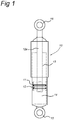
- a shock absorber 10 is shown in figure 1 and comprises a cylinder 11 and a piston 12 displaceable in the cylinder along a cylinder wall.
- the piston seals against the cylinder wall and divides the cylinder in a first chamber 13 and a second chamber 14.
- a cylinder attachment 15 is connected to the cylinder and a piston attachment 16 is connected to the piston 12.
- a piston rod 12a extends as a part of the piston 12 to the piston attachment 16.
- the piston and cylinder attachments are arranged for attachment to parts of a vehicle, which can move with respect to one another in order to damp their relative movement. Both attachments move towards one another in an inward movement and away from one another in an outward movement.
- the vehicle may generally be a car, but can also be another vehicle like a train or a bus. Movements of the car body with respect to a wheel are damped by a damper as disclosed when the car is travelling over a surface like a road surface.
- a fluid is contained in the cylinder chambers 13, 14 and can move in between cylinder chambers through flow and valve arrangements provided in and/or on the piston 12 according to the embodiments shown in the figures.
- the fluid can be a liquid, such as oil, or a gas, such as air.
- First outward valve 120 is a one-way valve closing off first outward channel 140 and may pass fluid in an outward flow direction from first cylinder chamber 13 to second cylinder chamber 14. Fluid can pass first outward valve 120 in different manners in three flow regimes. To achieve so the valve is embodied as a plate pack.
- the plate pack or valve 120 is held between intermediate piston part 12.2 and third valve seat 125 of top piston part 12.1, which are mounted on the piston rod 12a.
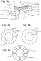
- the plate pack 120 comprises primary plates 121, open plate 122, recess plate 123 and closing plate 124, which are shown individually in figures 4a to 4d .
- Open plate 122 closes on first valve seat 125 with open plate 122.
- Open plate 122 has openings 122a at its outer perimeter, as shown in figure 4a , at positions associated with first valve seat 125 such that fluid flow may occur through openings 122a across first valve seat 125, as indicated by flow path F11 in figure 2 .
- Figure 4a shows a plan view of open plate 122 with openings (outer perimeter cut-outs) 122a at a radius corresponding to the radius of the circular first valve seat 125.
- Open plate 122 has an inner opening 122b that allows mounting of the open plate on the upper piston part 12.1 around the piston rod 12a.
- Primary plates 121 are mounted adjacent to the open plate 122 to provide a desired stiffness to the plate pack. Adding or deleting primary plates 121 would increase or reduce stiffness, respectively, of the plate pack and thus valve 120.
- a primary plate 121 is shown in plan view in figure 4b .
- Inner opening 121a allows mounting of the primary plate on the upper piston part 12.1 around the piston rod 12a.
- the outer radius of the primary plate 121 corresponds to the outer radius of the open plate 122. Fluid can pass in between piston rod 12a and primary and open plates 121, 122 through their respective inner openings 122b, 121a to arrive at recess plate 123 and cover plate 124.
- Recess plate 123 and cover plate 124 are shown in plan view in figures 4c and 4d , respectively.
- the recess plate comprises recesses or slits 123a that extend from the inner perimeter towards the outer perimeter of the recess plate.
- the length of the slits is smaller than the distance between inner and outer perimeters such that there is no open connection between inner and outer perimeters as viewed long the plane of the drawing of figure 4c ..
- Fluid can pass from first outward channel into the slit 123a of the recess plate 123.
- the cover plate 124 covers the recess plate to close off fluid flow through the slit 123a.
- the inner opening 123b of recess plate 123 allows passing of fluid and mounting of the recess plate on the upper piston part 12.1 around the piston rod 12a.
- the inner opening 124a of cover plate 124 allows mounting of the cover plate on the upper piston part 12.1 around the piston rod 12a.
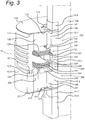
- the open plate 122 is dispensed with and small openings or grooves 125a are provided in the first valve seat to provide an open fluid connection F11 across valve 120, as is shown in figure 3a .
- the plate pack comprises a filler plate 126, 226 in between recess plate 123, 223 and cover plate 124, 224 at the inside perimeter of the recess plate and cover plate.
- the recesses 123a, 223a of the recess plate are in fluid communication with the side of the plate pack from which fluid passes the plate pack upon opening from the first valve seat 125, 225.
- the cover plate 124,224 rests on the recess plate at the outside perimeter of the recess plate and cover plate in a state when there is no fluid flow through the recesses of the recess plate.
- the filler plate is shown individually in figure 4e and has an inside perimeter with a diameter equal to the diameter of the inside perimeter of the cover plate.
- the outside perimeter of the filler plate is such that the filler plate has a ring shape and covers part of the recesses of the recess plate at the inside perimeter of the recess plate.
- the remainder of the recess plate is left uncovered by the filler plate. This leaves part of the recesses 123a, 223a uncovered by the filler plate.
- the plate pack is under a bias pressure in between valve seat 125 and part 12.2 such that the inside perimeters of the plates in the plate pack 220 are pressed downwards in figures 3 and 3a .
- first outward valve 120 In a first flow regime at a relative low pressure difference across first outward valve 120 fluid passes the valve through the openings 122a in the open plate or the grooves 125a in the first valve seat, as shown by flow path or fluid connection F11 in figure 2 . This will provide a soft damping behavior at relatively slow outward movements.
- first outward valve 120 At faster outward movements a larger pressure difference across first outward valve 120 will build up and cover plate 124 will open from recess plate 123 to allow additional fluid flow through slits 123a of the recess plate, as indicated by flow path F12 in figure 2 .
- the fluid flow F12 through the slits 123a as allowed by the cover plate 124 provides for a linear damping behavior.
- flow resistance increases at increased pressure difference across the valve. The characteristic is largely given by the resistance provided by the recesses (slits) and the stiffness and a bias force of the cover plate.
- Fluid connections F11 and F13 are indicated by the same fluid flow arrow in figure 2 . However, fluid connection F11 only concerns fluid flow through openings 112a or grooves 125a, while fluid connection F13 concerns a fluid flow when plate pack 120 opens from first valve seat 125.
- Second outward valve 210 is a plate-type valve that closes on second valve seat 211 in a rest position in which no pressure difference is present across the valve. The rest position is shown in more detail in figure 5a . Fluid may pass through the clearance in between plate-type valve 210 and third valve seat 212, and through openings 215 in the second outward valve 210. The clearance between valve 210 and third valve seat 212 provides for a constant open fluid connection across the second outward valve 210, as is shown by flow path F21 in figures 2 and 5a . In combination with the open fluid connection F11 across first outward valve 120 it provides for a constant open fluid connection from first cylinder chamber 13 to second cylinder chamber 14 on outward movements.
- Second inward valve 220 also provides openings 222a in an open plate 222 across a first valve seat 225 (alike across first valve seat 125), or alternatively grooves 225a in first valve seat 225 (similar as described with respect to first valve seat 125 of first outward valve 120).
- the constant fluid connection or flow F21a across second outward valve 220 on outward movements is in parallel to the constant flow connection F21 on outward movements across second outward valve 210.
- the valves are configured such that constant open fluid connection F21 provides for a larger fluid flow than fluid connection F21a since flow connection F21 provides for a larger flow-through cross-sectional area.
- the constant open fluid connection between first cylinder chamber 13 and second cylinder chamber 14 on outward movements is a combination of flow connection F11 in series with the parallel connection of fluid flows F21 and F21a.
- Flow connection F11 provides a more restricted flow than flow connection F21 since flow connection F11 has a smaller flow-through cross-sectional area.
- the constant fluid flow between cylinder chambers 13 and 14 on outward movements is therefore determined by fluid flow connection F11, and therefore by the flow-through cross-sectional area provided by openings 122a or grooves 125a.
- Second outward valve 210 At faster outward movements a larger fluid pressure will build up in the second outward channel to result in a larger pressure difference across second outward valve 210, which will open second outward valve 210 from second valve seat 211. Opening of second outward valve 210 from second valve seat 211 provides for a larger fluid flow through second outward channel 230, which is shown as fluid flow F22 in figure 5b .
- the second outward valve 210 is configured as a plate-type valve that is fixed at an inside position and has a free-moving outside perimeter.
- the plate-type valve is dimensioned and arranged such that it performs a rolling-like movement upon opening and closing. This provides for a silent valve that does not cause any noise at opening and closing movements.
- a cavitation that may occur for first outward valve 120 may cause a hiss-type noise. However, such noise will be largely reduced or even cancelled since such cavitation is enclosed within the space delimited by first and second piston parts 100 and 200.
- the configuration of first and second outward valves 120 and 210 as disclosed therefore provides for a silent damper.
- Second outward valve 210 therefore fully closes off fluid flow through second outward channel 230 at inward movements.
- first inward valve 110 closes off first inward channel 130 on outward movements.
- first outward channel 140 from first cylinder chamber 13.
- the damping behavior on outward movements is therefore only determined by the configuration of the first and second outward channels 140 and 230 and the first and second outward valves 120 and 210. It allows accurate tuning of the desired damping behavior by separately selecting a constant flow, a linear damping behavior and range, and a blow off force.
- Second inward valve similarly comprises open plate 222 with openings 222a and 222b, primary plates 221, recess plate 223 with slits 223a and opening 223b, and cover plate 224.
- Second inward valve similarly closes on first valve seat 225 (that in an alternative embodiment may have openings or grooves similarly to grooves 125a of first valve seat 125).
- Second outward valve 210 comprises plate-type valve 210 with openings 215.
- Second outward valve similarly closes on second valve seat 211 and third valve seat 212. All variables of the damping behavior of the damper for both inward and outward movements can be set independent from one another.
- First inward valve 110 and second outward valve 210 also act as one-way valves for the outward and inward flow paths between first and second cylinder chambers 13, 14, respectively, so as to make both flow paths fully independent from one another.
- the piston comprises a first piston part 12.1 on which the first inward valve 110 and first outward valve 120 are mounted with the aid of intermediate piston part 12.2. Together they constitute a first piston module 100.
- Second piston part 12.3 together with second inward valve 220 and second outward valve 210 constitute a second piston module 200.
- Either one or both of the first and second modules may be mounted on the piston rod to form a piston since each module has flow channels and valves for inward and a valve for outward movements.
- the modules are mounted with the aid of spacer parts 12.6, 12.7 and a nut part 12.9 that screws onto the piston rod 12a.
- An O-ring 12.5 acts as a seal in between the first and second modules 100, 200.
- Figure 6a shows a piston only having module 100 mounted.
- Figure 6b shows also only module 100 mounted, but upside down with respect to the configuration of figure 6b .
- Such module 100 upside down is basically a module 200 of figure 2 and 3 , but with an additional sealing arrangement for sealing against the cylinder wall of cylinder 11.
- the embodiments shown in figures 6a and 6b could comprise another plate pack or plate-type valve as disclosed, if desired.
- the damper can be provided as a kit with the two separate first and second modules 100, 200. At use one or both modules may then be mounted as required. In some applications one of both modules may be sufficient, whereas other applications may require both modules.
- Application of only the first module as shown in figure 6a would provide a damper that is generally less stiff on inward movements than a damper having both modules. Such a damper could be applied at wheels having a fixed wheel suspension, which are generally the rear wheels of a car.
- Application of both modules as shown in figures 2 and 3 would provide a damper that is generally stiffer than a damper having only one module. Such damper can be applied at wheels having an independent wheel suspension, which are generally the front wheels of a car.
- the kit may further comprise additional components to add an additional plate pack or plate-type valve, if desired, as disclosed in the previous paragraph.
- each set of similar associated channels has only one associated valve in the embodiments as disclosed.
- the disclosed embodiments with multiple associated similar channels and one associated valve seems preferred for reasons of efficiency, costs reliability and manufacturability.
- Various other embodiments of the invention will be apparent to the skilled person when having read the above disclosure in connection with the drawing, all of which are within the scope of the invention and accompanying claims.
Landscapes
- Engineering & Computer Science (AREA)
- General Engineering & Computer Science (AREA)
- Mechanical Engineering (AREA)
- Physics & Mathematics (AREA)
- Fluid Mechanics (AREA)
- Fluid-Damping Devices (AREA)
Claims (14)
- Stoßdämpfer (10), der umfasst- einen Zylinder (11)- einen Kolben (12), der entlang einer Zylinderwand in dem Kolben bewegbar ist, wobei der Kolben gegen die Zylinderwand abdichtet und den Zylinder in eine erste Zylinderkammer (13) auf einer ersten Kolbenseite des Kolbens und eine zweite Zylinderkammer (14) auf einer zweiten Kolbenseite des Kolbens unterteilt, wobei die zweite Kolbenseite der ersten Kolbenseite gegenüberliegt und die erste und die zweite Zylinderkammer mit einem Fluid gefüllt sind;- einen Zylinderanbringteil (15), der zum Anbringen an einem ersten Teil eines Fahrzeugs konstruiert und angeordnet ist und mit dem Zylinder (11) verbunden ist; und- einen Kolbenanbringteil (16), der zum Anbringen an einem zweiten Teil eines Fahrzeugs konstruiert und angeordnet ist und mit dem Kolben (12) verbunden ist,wobei der Kolbenanbringteil und der Zylinderanbringteil derart angeordnet sind, dass sie sich in einer nach innen gerichteten Bewegung aufeinander zu und in einer nach außen gerichteten Bewegung voneinander weg bewegen,
wobei der Kolben (12) umfasst-- einen Kanal (140, 240), der für eine Fluidverbindung zwischen der ersten und der zweiten Zylinderkammer (13; 14) konstruiert und angeordnet ist; und- - ein Ventil (120, 220), das derart konstruiert und angeordnet ist, dass es den Kanal (140, 240) für eine Fluidströmung in einer einer nach innen gerichteten Bewegung und einer nach außen gerichteten Bewegung in Abhängigkeit von einem Fluiddruck in dem Kanal öffnet, und zumindest im Wesentlichen den Kanal gegen eine Fluidströmung in der anderen der nach innen gerichteten und nach außen gerichteten Bewegung verschließt, wobei das Ventil einen Ventilplattenblock (120, 220) umfasst, wobei der Plattenblock gegen einen ersten Ventilsitz (125, 225) schließt und umfasst--- eine Ausnehmungsplatte (123, 223), die mindestens eine Ausnehmung (123a, 223a) in Fluidkommunikation mit einer Seite des Plattenblocks umfasst, von der aus ein Fluid beim Öffnen vom ersten Ventilsitz (125, 225) aus den Plattenblock durchströmen kann; und--- eine Abdeckplatte (124, 224), die an die Ausnehmungsplatte angrenzt, um die Ausnehmung abzudecken, wobei die Abdeckplatte und die Ausnehmung derart ausgeführt und angeordnet sind, dass beim Öffnen der Abdeckplatte relativ zu der Ausnehmungsplatte eine Fluidverbindung über den Plattenblock vorgesehen ist. - Stoßdämpfer nach Anspruch 1, bei dem die Ausnehmung (123a, 223a) als Schlitz (123a, 223a) ausgeführt ist, der sich von einem eines Innenumfangs und eines Außenumfangs der Ausnehmungsplatte (123, 223) in Richtung des anderen des Innen- beziehungsweise Außenumfangs erstreckt, wobei eine Länge des Schlitzes kleiner ist als ein Abstand zwischen dem Innen- und dem Außenumfang.
- Stoßdämpfer nach Anspruch 2, bei dem der andere des Innen- und Außenumfangs einem Ventilpackumfang, der dem ersten Ventilsitz (125, 225) zugeordnet ist, entspricht.
- Stoßdämpfer nach einem der vorhergehenden Ansprüche, bei dem ein Fluiddruck, bei dem die Abdeckplatte (124, 224) die Ausnehmung (123a, 223a) in der Ausnehmungsplatte (123, 223) öffnet, niedriger ist als ein Fluiddruck, bei dem der Plattenblock (120, 220) von dem ersten Ventilsitz (125, 225) aus öffnet.
- Stoßdämpfer nach einem der vorhergehenden Ansprüche, bei dem der Plattenblock (120, 220) umfasst- eine Füllplatte (126, 226) zwischen der Ausnehmungsplatte (123, 223) und der Abdeckplatte (124, 224) an einem des Innen- und Außenumfangs der Ausnehmungsplatte und der Abdeckplatte, an dem die mindestens eine Ausnehmung (123a, 223a) der Ausnehmungsplatte in Fluidkommunikation mit der Seite des Plattenblocks steht, von der aus ein Fluid beim Öffnen vom ersten Ventilsitz (125, 225) aus den Plattenblock durchströmen kann, so dass bei Abwesenheit einer Fluidströmung durch die mindestens eine Ausnehmung der Ausnehmungsplatte die Abdeckplatte an dem anderen des Innen- und Außenumfangs der Ausnehmungsplatte und der Abdeckplatte auf der Ausnehmungsplatte aufliegt.
- Stoßdämpfer nach einem der vorhergehenden Ansprüche, bei dem der Kolben umfasst- einen zusätzlichen Kanal (230, 130), der für eine Fluidverbindung zwischen der ersten und der zweiten Zylinderkammer (13, 14) konstruiert und angeordnet ist, wobei der zusätzliche Kanal bei der einen der nach innen gerichteten Bewegung und der nach außen gerichteten Bewegung stromabwärts des Ventils angeordnet ist; und- ein zusätzliches Ventil (210, 110), das derart konstruiert und angeordnet ist, dass es den zusätzlichen Kanal für eine Fluidströmung bei der einen der nach innen gerichteten Bewegung und der nach außen gerichteten Bewegung in Abhängigkeit von einem Fluiddruck in dem zusätzlichen Kanal öffnet, und im Wesentlichen den zusätzlichen Kanal bei der anderen der nach innen gerichteten Bewegung und der nach außen gerichteten Bewegung verschließt, wobei das zusätzliche Ventil ein Plattenventil (210, 110) umfasst.
- Stoßdämpfer nach dem vorhergehenden Anspruch, bei dem das Plattenventil (110, 210) derart ausgeführt und angeordnet ist, dass es gegen einen zweiten Ventilsitz (111, 211) und einen dritten Ventilsitz (112, 212) schließt, wobei das Plattenventil- gegen den zweiten und den dritten Ventilsitz schließt bei einer Fluidströmung von einer Seite des Plattenventils gegenüber einer Seite, die dem zweiten und dem dritten Ventilsitz zugeordnet ist,- gegen den zweiten Ventilsitz schließt in einer Ruheposition ohne entweder die nach innen gerichtete oder die nach außen gerichtete Bewegung, wobei in der Ruheposition ein Spiel zwischen dem dritten Ventilsitz und dem Plattenventil vorgesehen ist, und- von dem zweiten Ventilsitz aus öffnet bei einer Fluidströmung von der Seite des Plattenventils aus, die dem zweiten und dem dritten Ventilsitz zugeordnet ist.
- Stoßdämpfer nach dem vorhergehenden Anspruch, bei dem das Plattenventil (110, 210) mindestens eine Öffnung (115, 215) umfasst, die einer Position auf einer Seite des dritten Ventilsitzes (112, 212) zugeordnet ist, die von dem zweiten Ventilsitz (111, 211) abgewandt ist.
- Stoßdämpfer nach einem der vorhergehenden drei Ansprüche, bei dem das Plattenventil (110, 210) derart ausgeführt und angeordnet ist, dass es eine Rollbewegung beim Öffnen oder Schließen ausführt.
- Stoßdämpfer nach einem der vorhergehenden vier Ansprüche, bei dem das Plattenventil (110, 210) an einer Innenposition des Plattenventils befestigt ist, wobei ein freier Außenumfang des Plattenventils vorgesehen ist.
- Stoßdämpfer nach einem der vorhergehenden Ansprüche, bei dem der Plattenblock mehr als eine Platte (121, 212) umfasst, um eine erforderliche Steifigkeit bereitzustellen.
- Stoßdämpfer nach einem der vorhergehenden Ansprüche, bei dem der Plattenblock (120, 220) eine offene Platte (122, 222) umfasst, die eine offene Strömungsverbindung über den Plattenblock bereitstellt.
- Stoßdämpfer nach dem vorhergehenden Anspruch, bei dem die offene Platte (122, 222) in dem Plattenblock (120, 220) derart vorgesehen ist, dass die offene Platte gegen den ersten Ventilsitz (125, 225) schließt und mindestens eine Öffnung oder einen Umfangsausschnitt (122a, 222a) an einer Position umfasst, die dem ersten Ventilsitz zugeordnet ist, wobei die Öffnung die offene Strömungsverbindung bereitstellt.
- Stoßdämpfer nach einem der vorhergehenden Ansprüche, bei dem der erste Ventilsitz (125, 225) mindestens eine Öffnung oder Nut (125a, 215a) umfasst, die die offene Strömungsverbindung über den Plattenblock (120, 220) bereitstellt.
Priority Applications (2)
| Application Number | Priority Date | Filing Date | Title |
|---|---|---|---|
| EP19168225.1A EP3584465A1 (de) | 2012-12-21 | 2013-07-01 | Stossdämpfer |
| PL13739842T PL2935933T3 (pl) | 2012-12-21 | 2013-07-01 | Amortyzator wstrząsów |
Applications Claiming Priority (2)
| Application Number | Priority Date | Filing Date | Title |
|---|---|---|---|
| NL2010038A NL2010038C2 (en) | 2012-12-21 | 2012-12-21 | Shock absorber. |
| PCT/NL2013/050476 WO2014098570A1 (en) | 2012-12-21 | 2013-07-01 | Shock absorber |
Related Child Applications (1)
| Application Number | Title | Priority Date | Filing Date |
|---|---|---|---|
| EP19168225.1A Division EP3584465A1 (de) | 2012-12-21 | 2013-07-01 | Stossdämpfer |
Publications (2)
| Publication Number | Publication Date |
|---|---|
| EP2935933A1 EP2935933A1 (de) | 2015-10-28 |
| EP2935933B1 true EP2935933B1 (de) | 2019-04-10 |
Family
ID=47748731
Family Applications (3)
| Application Number | Title | Priority Date | Filing Date |
|---|---|---|---|
| EP19168225.1A Withdrawn EP3584465A1 (de) | 2012-12-21 | 2013-07-01 | Stossdämpfer |
| EP13739842.6A Active EP2935933B1 (de) | 2012-12-21 | 2013-07-01 | Stossdämpfer |
| EP13818511.1A Active EP2935934B1 (de) | 2012-12-21 | 2013-12-20 | Stossdämpfer |
Family Applications Before (1)
| Application Number | Title | Priority Date | Filing Date |
|---|---|---|---|
| EP19168225.1A Withdrawn EP3584465A1 (de) | 2012-12-21 | 2013-07-01 | Stossdämpfer |
Family Applications After (1)
| Application Number | Title | Priority Date | Filing Date |
|---|---|---|---|
| EP13818511.1A Active EP2935934B1 (de) | 2012-12-21 | 2013-12-20 | Stossdämpfer |
Country Status (12)
| Country | Link |
|---|---|
| US (3) | US9631695B2 (de) |
| EP (3) | EP3584465A1 (de) |
| CN (3) | CN109555808A (de) |
| BR (2) | BR112015014910A2 (de) |
| DK (1) | DK2935934T3 (de) |
| ES (2) | ES2732851T3 (de) |
| HU (1) | HUE032496T2 (de) |
| LT (1) | LT2935934T (de) |
| NL (1) | NL2010038C2 (de) |
| PL (2) | PL2935933T3 (de) |
| PT (1) | PT2935934T (de) |
| WO (2) | WO2014098570A1 (de) |
Families Citing this family (34)
| Publication number | Priority date | Publication date | Assignee | Title |
|---|---|---|---|---|
| EP3241902B1 (de) | 2012-05-25 | 2018-02-28 | The Regents of The University of California | Verfahren und zusammensetzungen zur rna-gesteuerten ziel-dna-modifikation und zur rna-gesteuerten transkriptionsmodulation |
| NL2010038C2 (en) * | 2012-12-21 | 2014-06-24 | Koni Bv | Shock absorber. |
| US9638280B2 (en) | 2013-08-26 | 2017-05-02 | Tenneco Automotive Operating Company Inc. | Shock absorber with frequency dependent passive valve |
| JP5783646B2 (ja) * | 2013-11-08 | 2015-09-24 | カヤバ工業株式会社 | バルブ |
| US9441700B2 (en) | 2014-08-14 | 2016-09-13 | Tenneco Automotive Operating Company Inc. | Shock absorber with frequency dependent passive valve |
| US9222539B1 (en) * | 2014-08-14 | 2015-12-29 | Tenneco Automotive Operating Company Inc. | Shock absorber with frequency dependent passive valve |
| KR102471853B1 (ko) * | 2015-10-22 | 2022-11-30 | 에이치엘만도 주식회사 | 감쇠력 가변식 쇽업소버 |
| NL2015876B1 (en) * | 2015-11-27 | 2017-06-14 | Koni Bv | Frequency-selective damper valve, and shock absorber and piston having such valve. |
| BE1023718B1 (nl) | 2016-01-01 | 2017-06-26 | Shi Yan | Schokdemper met frequentie afhankelijk zuigersamenstel |
| DE102016208844A1 (de) * | 2016-05-23 | 2017-11-23 | Thyssenkrupp Ag | Frequenzselektiver Schwingungsdämpfer für Kraftfahrzeuge mit einem Bypasssteuerventil |
| KR102627181B1 (ko) * | 2017-02-27 | 2024-01-19 | 에이치엘만도 주식회사 | 감쇠력 가변식 쇽업소버 |
| WO2018163868A1 (ja) * | 2017-03-10 | 2018-09-13 | 日立オートモティブシステムズ株式会社 | 緩衝器 |
| US10563721B2 (en) | 2017-04-24 | 2020-02-18 | Beijingwest Industries Co., Ltd | Hydraulic damper having a high frequency valve assembly |
| US10648527B2 (en) | 2017-04-24 | 2020-05-12 | Beijingwest Industries Co., Ltd. | Twin tube damper including a pressure rate sensitive system |
| JP6701242B2 (ja) * | 2018-02-21 | 2020-05-27 | Kyb株式会社 | バルブおよび緩衝器 |
| US10787052B2 (en) * | 2018-07-18 | 2020-09-29 | Ford Global Technologies, Llc | Vehicle tow hook |
| EP3832158B1 (de) * | 2018-07-31 | 2026-04-22 | Astemo, Ltd. | Ventilmechanismus und stossdämpfer |
| CN111536186B (zh) | 2019-05-06 | 2021-07-23 | 北京京西重工有限公司 | 阻尼器组件和用于阻尼器组件的活塞 |
| CN110588457B (zh) * | 2019-10-18 | 2024-08-20 | 安路普(北京)汽车技术有限公司 | 一种高度调节装置、座椅以及车辆悬架系统 |
| EP4127506A1 (de) * | 2020-03-27 | 2023-02-08 | DRiV Automotive Inc. | Dämpferanordnung |
| CN112161015B (zh) | 2020-10-28 | 2022-05-06 | 北京京西重工有限公司 | 液压阻尼器组件和用于液压阻尼器组件的附加活塞 |
| CN114542647A (zh) * | 2020-11-27 | 2022-05-27 | 比亚迪股份有限公司 | 用于减振器的阀系组件和具有其的减振器 |
| JP7470076B2 (ja) * | 2021-03-19 | 2024-04-17 | カヤバ株式会社 | バルブおよび緩衝器 |
| CN116997731A (zh) * | 2021-03-29 | 2023-11-03 | 日立安斯泰莫株式会社 | 缓冲器以及阀装置 |
| ES3020059T3 (en) * | 2021-04-12 | 2025-05-21 | Beijingwest Ind Co Ltd | Hydraulic damper with piston assembly having blow-off valves |
| CN113074206B (zh) | 2021-04-12 | 2022-03-22 | 北京京西重工有限公司 | 液压阻尼器 |
| US20230160450A1 (en) * | 2021-11-22 | 2023-05-25 | Edward Asbury | Linear and Progressive Valve Assemblies For Digressive Shock Absorber |
| CN113983106B (zh) * | 2021-11-25 | 2022-05-24 | 宁波瑞丰汽车零部件有限公司 | 低速流量可调的减震器活塞 |
| CN114542649A (zh) * | 2022-03-20 | 2022-05-27 | 四川宁江山川机械有限责任公司 | 一种频率自适应减震器 |
| DE102022207973A1 (de) * | 2022-08-02 | 2024-02-08 | Zf Friedrichshafen Ag | Dämpfventilanordnung für einen Schwingungsdämpfer sowie Schwingungsdämpfer mit der Dämpfventilanordnung und Verfahren zur Bestückung eines Schwingungsdämpfers |
| US20240376953A1 (en) * | 2023-05-08 | 2024-11-14 | DRiV Automotive Inc. | Fulcrum and check discs for shock absorber with optimized bleed range and tuneability |
| CN120100848A (zh) * | 2023-12-06 | 2025-06-06 | 罗兰克斯轴承(南京)有限公司 | 一种频率自适应阻尼阀组件及使用该阀组件的减振器 |
| CN120100847A (zh) * | 2023-12-06 | 2025-06-06 | 罗兰克斯轴承(南京)有限公司 | 一种fad阀组及使用该阀组的减振器 |
| CN120100849A (zh) * | 2023-12-06 | 2025-06-06 | 罗兰克斯轴承(南京)有限公司 | 一种频率自适应阻尼阀组件及使用该阀组件的减振器 |
Family Cites Families (35)
| Publication number | Priority date | Publication date | Assignee | Title |
|---|---|---|---|---|
| US2740500A (en) * | 1951-06-29 | 1956-04-03 | Gen Motors Corp | Shock absorber |
| DE1249037B (de) * | 1961-06-02 | 1967-08-31 | ||
| EP0174119B1 (de) * | 1984-09-04 | 1989-07-19 | General Motors Corporation | Hydraulische Dämpfungseinheit |
| US5217095A (en) * | 1986-06-05 | 1993-06-08 | Monroe Auto Equipment Company | Method and apparatus for absorbing mechanical shock |
| US5316113A (en) * | 1987-11-19 | 1994-05-31 | Atsugi Motor Parts Company Ltd. | Hydraulic shock absorber |
| JPH01102536U (de) * | 1987-12-28 | 1989-07-11 | ||
| US5129488A (en) | 1989-11-16 | 1992-07-14 | Atsugi Unisia Corporation | Vibration mode responsive variable damping force shock absorber with feature of automatic selection of damping mode depending upon vibration mode of vehicular body |
| US5261448A (en) * | 1989-11-16 | 1993-11-16 | Atsugi Unisia Corp. | Vibration mode responsive variable damping force shock absorber with feature of automatic selection of damping mode depending upon vibration mode of vehicular body |
| JP2918293B2 (ja) * | 1990-05-28 | 1999-07-12 | 株式会社ユニシアジェックス | 減衰力可変型緩衝器 |
| DE4212078A1 (de) * | 1992-04-10 | 1993-10-14 | Stabilus Gmbh | Endlagendämpfer |
| US5823305A (en) * | 1992-10-08 | 1998-10-20 | Ricor Racing & Development, L.P. | Flow sensitive, acceleration sensitive shock absorber |
| SE506443C2 (sv) * | 1992-12-09 | 1997-12-15 | Oehlins Racing Ab | Anordning vid stötdämpare |
| JPH07233840A (ja) * | 1994-02-22 | 1995-09-05 | Unisia Jecs Corp | 減衰力可変型ショックアブソーバ |
| DE59501816D1 (de) * | 1994-05-13 | 1998-05-14 | Rieter Ingolstadt Spinnerei | Verfahren und Vorrichtung zur Trennung des Faserbandes an einer Faserband abliefernden Textilmaschine |
| JP3733496B2 (ja) * | 1996-11-12 | 2006-01-11 | 株式会社日立製作所 | 減衰力調整式油圧緩衝器 |
| US5823306A (en) * | 1996-11-12 | 1998-10-20 | Tenneco Automotive Inc. | Stroke dependent damping |
| JP4055023B2 (ja) | 1997-09-24 | 2008-03-05 | 株式会社日立製作所 | 減衰力調整式油圧緩衝器 |
| US6460664B1 (en) * | 2000-05-22 | 2002-10-08 | Tenneco Automotive Inc. | Independently tunable variable bleed orifice |
| JP4587089B2 (ja) * | 2000-05-31 | 2010-11-24 | 日立オートモティブシステムズ株式会社 | 減衰力調整式油圧緩衝器 |
| US6340081B1 (en) * | 2000-06-23 | 2002-01-22 | Tenneco Automotive Inc. | Shock absorber having ported plate low speed tunability |
| US6450304B1 (en) * | 2001-02-12 | 2002-09-17 | Delphi Technologies, Inc. | Piston and rod assembly for air-actuated variable damping |
| NL1019313C2 (nl) | 2001-11-06 | 2003-05-12 | Koni Bv | Schokdemper met frequentie afhankelijke demping. |
| CN100526674C (zh) * | 2004-05-25 | 2009-08-12 | 日产自动车株式会社 | 液压缓冲器 |
| JP4318080B2 (ja) * | 2004-06-07 | 2009-08-19 | 株式会社日立製作所 | 油圧緩衝器 |
| JP4987283B2 (ja) | 2005-11-09 | 2012-07-25 | カヤバ工業株式会社 | 緩衝器のバルブ構造および緩衝器 |
| NL1031880C2 (nl) * | 2006-05-24 | 2007-11-30 | Koni Bv | Eenwegklep voor een schokdemper. |
| DE102007019621B4 (de) * | 2007-04-24 | 2013-09-05 | Reinhard Hölscher | Frequenzabhängiger Schwingungsdämpfer |
| JP2009014019A (ja) | 2007-06-29 | 2009-01-22 | Hitachi Ltd | 緩衝器 |
| JP2009079710A (ja) * | 2007-09-26 | 2009-04-16 | Showa Corp | 油圧緩衝器の減衰力調整構造 |
| ES2386483T3 (es) | 2008-07-02 | 2012-08-21 | Koni B.V. | Válvula amortiguadora |
| JP5387841B2 (ja) | 2009-09-30 | 2014-01-15 | 日立オートモティブシステムズ株式会社 | 減衰力調整式緩衝器 |
| NL2004138C2 (nl) * | 2010-01-25 | 2011-07-26 | Koni Bv | Stijve demper. |
| JP5859813B2 (ja) * | 2010-12-28 | 2016-02-16 | 日立オートモティブシステムズ株式会社 | 緩衝器 |
| KR101254233B1 (ko) * | 2011-05-31 | 2013-04-18 | 주식회사 만도 | 쇽업소버의 밸브 구조 |
| NL2010038C2 (en) * | 2012-12-21 | 2014-06-24 | Koni Bv | Shock absorber. |
-
2012
- 2012-12-21 NL NL2010038A patent/NL2010038C2/en not_active IP Right Cessation
-
2013
- 2013-07-01 ES ES13739842T patent/ES2732851T3/es active Active
- 2013-07-01 US US14/652,555 patent/US9631695B2/en not_active Expired - Fee Related
- 2013-07-01 CN CN201810750148.5A patent/CN109555808A/zh active Pending
- 2013-07-01 EP EP19168225.1A patent/EP3584465A1/de not_active Withdrawn
- 2013-07-01 BR BR112015014910A patent/BR112015014910A2/pt not_active Application Discontinuation
- 2013-07-01 CN CN201380069734.9A patent/CN104903611B/zh active Active
- 2013-07-01 WO PCT/NL2013/050476 patent/WO2014098570A1/en not_active Ceased
- 2013-07-01 PL PL13739842T patent/PL2935933T3/pl unknown
- 2013-07-01 EP EP13739842.6A patent/EP2935933B1/de active Active
- 2013-12-20 EP EP13818511.1A patent/EP2935934B1/de active Active
- 2013-12-20 PL PL13818511T patent/PL2935934T3/pl unknown
- 2013-12-20 ES ES13818511.1T patent/ES2625424T3/es active Active
- 2013-12-20 PT PT138185111T patent/PT2935934T/pt unknown
- 2013-12-20 BR BR112015014931A patent/BR112015014931A2/pt not_active Application Discontinuation
- 2013-12-20 DK DK13818511.1T patent/DK2935934T3/en active
- 2013-12-20 US US14/654,095 patent/US9982740B2/en active Active
- 2013-12-20 WO PCT/NL2013/050936 patent/WO2014104876A1/en not_active Ceased
- 2013-12-20 HU HUE13818511A patent/HUE032496T2/en unknown
- 2013-12-20 CN CN201380069751.2A patent/CN104919206B/zh active Active
- 2013-12-20 LT LTEP13818511.1T patent/LT2935934T/lt unknown
-
2017
- 2017-03-29 US US15/472,347 patent/US9982739B2/en active Active
Non-Patent Citations (1)
| Title |
|---|
| None * |
Also Published As
| Publication number | Publication date |
|---|---|
| EP2935933A1 (de) | 2015-10-28 |
| US9631695B2 (en) | 2017-04-25 |
| CN104919206A (zh) | 2015-09-16 |
| US9982739B2 (en) | 2018-05-29 |
| US20150345586A1 (en) | 2015-12-03 |
| EP2935934B1 (de) | 2017-04-19 |
| CN104903611B (zh) | 2018-07-31 |
| CN104903611A (zh) | 2015-09-09 |
| WO2014104876A1 (en) | 2014-07-03 |
| CN109555808A (zh) | 2019-04-02 |
| CN104919206B (zh) | 2017-09-29 |
| NL2010038C2 (en) | 2014-06-24 |
| WO2014098570A1 (en) | 2014-06-26 |
| US20170198778A1 (en) | 2017-07-13 |
| PT2935934T (pt) | 2017-06-02 |
| PL2935933T3 (pl) | 2019-09-30 |
| EP3584465A1 (de) | 2019-12-25 |
| US9982740B2 (en) | 2018-05-29 |
| BR112015014931A2 (pt) | 2017-07-11 |
| EP2935934A1 (de) | 2015-10-28 |
| DK2935934T3 (en) | 2017-05-22 |
| PL2935934T3 (pl) | 2017-09-29 |
| HUE032496T2 (en) | 2017-09-28 |
| LT2935934T (lt) | 2017-07-25 |
| BR112015014910A2 (pt) | 2017-07-11 |
| ES2625424T3 (es) | 2017-07-19 |
| US20150323037A1 (en) | 2015-11-12 |
| ES2732851T3 (es) | 2019-11-26 |
Similar Documents
| Publication | Publication Date | Title |
|---|---|---|
| EP2935933B1 (de) | Stossdämpfer | |
| CN113167352B (zh) | 具有多个外部控制阀的阻尼器 | |
| US9067471B2 (en) | Piston assembly with open bleed | |
| NL2015875B1 (en) | Shock absorber with comfort valve. | |
| US10830304B2 (en) | Frequency-selective damper valve, and shock absorber and piston having such valve | |
| GB2328999A (en) | A gas pressure shock absorber | |
| CN108700155A (zh) | 具有改进的活塞结构的减震器 | |
| US10851903B2 (en) | Check valve assembly |
Legal Events
| Date | Code | Title | Description |
|---|---|---|---|
| PUAI | Public reference made under article 153(3) epc to a published international application that has entered the european phase |
Free format text: ORIGINAL CODE: 0009012 |
|
| 17P | Request for examination filed |
Effective date: 20150720 |
|
| AK | Designated contracting states |
Kind code of ref document: A1 Designated state(s): AL AT BE BG CH CY CZ DE DK EE ES FI FR GB GR HR HU IE IS IT LI LT LU LV MC MK MT NL NO PL PT RO RS SE SI SK SM TR |
|
| AX | Request for extension of the european patent |
Extension state: BA ME |
|
| DAX | Request for extension of the european patent (deleted) | ||
| STAA | Information on the status of an ep patent application or granted ep patent |
Free format text: STATUS: EXAMINATION IS IN PROGRESS |
|
| 17Q | First examination report despatched |
Effective date: 20161213 |
|
| REG | Reference to a national code |
Ref country code: DE Ref legal event code: R079 Ref document number: 602013053674 Country of ref document: DE Free format text: PREVIOUS MAIN CLASS: F16F0009460000 Ipc: F16F0009180000 |
|
| RIC1 | Information provided on ipc code assigned before grant |
Ipc: F16F 9/46 20060101ALI20180720BHEP Ipc: F16F 9/44 20060101ALI20180720BHEP Ipc: F16F 9/18 20060101AFI20180720BHEP Ipc: F16F 9/516 20060101ALI20180720BHEP Ipc: F16F 9/512 20060101ALI20180720BHEP Ipc: F16F 9/348 20060101ALI20180720BHEP |
|
| GRAP | Despatch of communication of intention to grant a patent |
Free format text: ORIGINAL CODE: EPIDOSNIGR1 |
|
| STAA | Information on the status of an ep patent application or granted ep patent |
Free format text: STATUS: GRANT OF PATENT IS INTENDED |
|
| RIN1 | Information on inventor provided before grant (corrected) |
Inventor name: DE KOCK, PAUL |
|
| INTG | Intention to grant announced |
Effective date: 20181022 |
|
| GRAS | Grant fee paid |
Free format text: ORIGINAL CODE: EPIDOSNIGR3 |
|
| GRAA | (expected) grant |
Free format text: ORIGINAL CODE: 0009210 |
|
| STAA | Information on the status of an ep patent application or granted ep patent |
Free format text: STATUS: THE PATENT HAS BEEN GRANTED |
|
| AK | Designated contracting states |
Kind code of ref document: B1 Designated state(s): AL AT BE BG CH CY CZ DE DK EE ES FI FR GB GR HR HU IE IS IT LI LT LU LV MC MK MT NL NO PL PT RO RS SE SI SK SM TR |
|
| REG | Reference to a national code |
Ref country code: GB Ref legal event code: FG4D |
|
| REG | Reference to a national code |
Ref country code: CH Ref legal event code: EP Ref country code: AT Ref legal event code: REF Ref document number: 1119088 Country of ref document: AT Kind code of ref document: T Effective date: 20190415 |
|
| REG | Reference to a national code |
Ref country code: IE Ref legal event code: FG4D |
|
| REG | Reference to a national code |
Ref country code: DE Ref legal event code: R096 Ref document number: 602013053674 Country of ref document: DE |
|
| REG | Reference to a national code |
Ref country code: NL Ref legal event code: FP |
|
| REG | Reference to a national code |
Ref country code: SE Ref legal event code: TRGR |
|
| REG | Reference to a national code |
Ref country code: LT Ref legal event code: MG4D |
|
| REG | Reference to a national code |
Ref country code: AT Ref legal event code: MK05 Ref document number: 1119088 Country of ref document: AT Kind code of ref document: T Effective date: 20190410 |
|
| PG25 | Lapsed in a contracting state [announced via postgrant information from national office to epo] |
Ref country code: AL Free format text: LAPSE BECAUSE OF FAILURE TO SUBMIT A TRANSLATION OF THE DESCRIPTION OR TO PAY THE FEE WITHIN THE PRESCRIBED TIME-LIMIT Effective date: 20190410 Ref country code: PT Free format text: LAPSE BECAUSE OF FAILURE TO SUBMIT A TRANSLATION OF THE DESCRIPTION OR TO PAY THE FEE WITHIN THE PRESCRIBED TIME-LIMIT Effective date: 20190910 Ref country code: LT Free format text: LAPSE BECAUSE OF FAILURE TO SUBMIT A TRANSLATION OF THE DESCRIPTION OR TO PAY THE FEE WITHIN THE PRESCRIBED TIME-LIMIT Effective date: 20190410 Ref country code: HR Free format text: LAPSE BECAUSE OF FAILURE TO SUBMIT A TRANSLATION OF THE DESCRIPTION OR TO PAY THE FEE WITHIN THE PRESCRIBED TIME-LIMIT Effective date: 20190410 Ref country code: NO Free format text: LAPSE BECAUSE OF FAILURE TO SUBMIT A TRANSLATION OF THE DESCRIPTION OR TO PAY THE FEE WITHIN THE PRESCRIBED TIME-LIMIT Effective date: 20190710 Ref country code: FI Free format text: LAPSE BECAUSE OF FAILURE TO SUBMIT A TRANSLATION OF THE DESCRIPTION OR TO PAY THE FEE WITHIN THE PRESCRIBED TIME-LIMIT Effective date: 20190410 |
|
| PGFP | Annual fee paid to national office [announced via postgrant information from national office to epo] |
Ref country code: FR Payment date: 20190725 Year of fee payment: 7 |
|
| REG | Reference to a national code |
Ref country code: ES Ref legal event code: FG2A Ref document number: 2732851 Country of ref document: ES Kind code of ref document: T3 Effective date: 20191126 |
|
| PG25 | Lapsed in a contracting state [announced via postgrant information from national office to epo] |
Ref country code: GR Free format text: LAPSE BECAUSE OF FAILURE TO SUBMIT A TRANSLATION OF THE DESCRIPTION OR TO PAY THE FEE WITHIN THE PRESCRIBED TIME-LIMIT Effective date: 20190711 Ref country code: BG Free format text: LAPSE BECAUSE OF FAILURE TO SUBMIT A TRANSLATION OF THE DESCRIPTION OR TO PAY THE FEE WITHIN THE PRESCRIBED TIME-LIMIT Effective date: 20190710 Ref country code: RS Free format text: LAPSE BECAUSE OF FAILURE TO SUBMIT A TRANSLATION OF THE DESCRIPTION OR TO PAY THE FEE WITHIN THE PRESCRIBED TIME-LIMIT Effective date: 20190410 Ref country code: LV Free format text: LAPSE BECAUSE OF FAILURE TO SUBMIT A TRANSLATION OF THE DESCRIPTION OR TO PAY THE FEE WITHIN THE PRESCRIBED TIME-LIMIT Effective date: 20190410 |
|
| PG25 | Lapsed in a contracting state [announced via postgrant information from national office to epo] |
Ref country code: IS Free format text: LAPSE BECAUSE OF FAILURE TO SUBMIT A TRANSLATION OF THE DESCRIPTION OR TO PAY THE FEE WITHIN THE PRESCRIBED TIME-LIMIT Effective date: 20190810 Ref country code: AT Free format text: LAPSE BECAUSE OF FAILURE TO SUBMIT A TRANSLATION OF THE DESCRIPTION OR TO PAY THE FEE WITHIN THE PRESCRIBED TIME-LIMIT Effective date: 20190410 |
|
| REG | Reference to a national code |
Ref country code: DE Ref legal event code: R097 Ref document number: 602013053674 Country of ref document: DE |
|
| PG25 | Lapsed in a contracting state [announced via postgrant information from national office to epo] |
Ref country code: EE Free format text: LAPSE BECAUSE OF FAILURE TO SUBMIT A TRANSLATION OF THE DESCRIPTION OR TO PAY THE FEE WITHIN THE PRESCRIBED TIME-LIMIT Effective date: 20190410 Ref country code: DK Free format text: LAPSE BECAUSE OF FAILURE TO SUBMIT A TRANSLATION OF THE DESCRIPTION OR TO PAY THE FEE WITHIN THE PRESCRIBED TIME-LIMIT Effective date: 20190410 Ref country code: SK Free format text: LAPSE BECAUSE OF FAILURE TO SUBMIT A TRANSLATION OF THE DESCRIPTION OR TO PAY THE FEE WITHIN THE PRESCRIBED TIME-LIMIT Effective date: 20190410 Ref country code: RO Free format text: LAPSE BECAUSE OF FAILURE TO SUBMIT A TRANSLATION OF THE DESCRIPTION OR TO PAY THE FEE WITHIN THE PRESCRIBED TIME-LIMIT Effective date: 20190410 |
|
| PLBE | No opposition filed within time limit |
Free format text: ORIGINAL CODE: 0009261 |
|
| STAA | Information on the status of an ep patent application or granted ep patent |
Free format text: STATUS: NO OPPOSITION FILED WITHIN TIME LIMIT |
|
| PG25 | Lapsed in a contracting state [announced via postgrant information from national office to epo] |
Ref country code: MC Free format text: LAPSE BECAUSE OF FAILURE TO SUBMIT A TRANSLATION OF THE DESCRIPTION OR TO PAY THE FEE WITHIN THE PRESCRIBED TIME-LIMIT Effective date: 20190410 Ref country code: SM Free format text: LAPSE BECAUSE OF FAILURE TO SUBMIT A TRANSLATION OF THE DESCRIPTION OR TO PAY THE FEE WITHIN THE PRESCRIBED TIME-LIMIT Effective date: 20190410 |
|
| REG | Reference to a national code |
Ref country code: CH Ref legal event code: PL |
|
| 26N | No opposition filed |
Effective date: 20200113 |
|
| PG25 | Lapsed in a contracting state [announced via postgrant information from national office to epo] |
Ref country code: TR Free format text: LAPSE BECAUSE OF FAILURE TO SUBMIT A TRANSLATION OF THE DESCRIPTION OR TO PAY THE FEE WITHIN THE PRESCRIBED TIME-LIMIT Effective date: 20190410 |
|
| PG25 | Lapsed in a contracting state [announced via postgrant information from national office to epo] |
Ref country code: CH Free format text: LAPSE BECAUSE OF NON-PAYMENT OF DUE FEES Effective date: 20190731 Ref country code: LI Free format text: LAPSE BECAUSE OF NON-PAYMENT OF DUE FEES Effective date: 20190731 Ref country code: LU Free format text: LAPSE BECAUSE OF NON-PAYMENT OF DUE FEES Effective date: 20190701 Ref country code: SI Free format text: LAPSE BECAUSE OF FAILURE TO SUBMIT A TRANSLATION OF THE DESCRIPTION OR TO PAY THE FEE WITHIN THE PRESCRIBED TIME-LIMIT Effective date: 20190410 |
|
| PG25 | Lapsed in a contracting state [announced via postgrant information from national office to epo] |
Ref country code: IE Free format text: LAPSE BECAUSE OF NON-PAYMENT OF DUE FEES Effective date: 20190701 |
|
| PG25 | Lapsed in a contracting state [announced via postgrant information from national office to epo] |
Ref country code: FR Free format text: LAPSE BECAUSE OF NON-PAYMENT OF DUE FEES Effective date: 20200731 |
|
| PG25 | Lapsed in a contracting state [announced via postgrant information from national office to epo] |
Ref country code: CY Free format text: LAPSE BECAUSE OF FAILURE TO SUBMIT A TRANSLATION OF THE DESCRIPTION OR TO PAY THE FEE WITHIN THE PRESCRIBED TIME-LIMIT Effective date: 20190410 |
|
| PG25 | Lapsed in a contracting state [announced via postgrant information from national office to epo] |
Ref country code: HU Free format text: LAPSE BECAUSE OF FAILURE TO SUBMIT A TRANSLATION OF THE DESCRIPTION OR TO PAY THE FEE WITHIN THE PRESCRIBED TIME-LIMIT; INVALID AB INITIO Effective date: 20130701 Ref country code: MT Free format text: LAPSE BECAUSE OF FAILURE TO SUBMIT A TRANSLATION OF THE DESCRIPTION OR TO PAY THE FEE WITHIN THE PRESCRIBED TIME-LIMIT Effective date: 20190410 |
|
| PG25 | Lapsed in a contracting state [announced via postgrant information from national office to epo] |
Ref country code: MK Free format text: LAPSE BECAUSE OF FAILURE TO SUBMIT A TRANSLATION OF THE DESCRIPTION OR TO PAY THE FEE WITHIN THE PRESCRIBED TIME-LIMIT Effective date: 20190410 |
|
| P01 | Opt-out of the competence of the unified patent court (upc) registered |
Effective date: 20230528 |
|
| PGFP | Annual fee paid to national office [announced via postgrant information from national office to epo] |
Ref country code: PL Payment date: 20250625 Year of fee payment: 13 |
|
| PGFP | Annual fee paid to national office [announced via postgrant information from national office to epo] |
Ref country code: GB Payment date: 20250619 Year of fee payment: 13 |
|
| PGFP | Annual fee paid to national office [announced via postgrant information from national office to epo] |
Ref country code: NL Payment date: 20250620 Year of fee payment: 13 Ref country code: BE Payment date: 20250619 Year of fee payment: 13 |
|
| PGFP | Annual fee paid to national office [announced via postgrant information from national office to epo] |
Ref country code: CZ Payment date: 20250625 Year of fee payment: 13 |
|
| PGFP | Annual fee paid to national office [announced via postgrant information from national office to epo] |
Ref country code: SE Payment date: 20250619 Year of fee payment: 13 |
|
| PGFP | Annual fee paid to national office [announced via postgrant information from national office to epo] |
Ref country code: ES Payment date: 20250801 Year of fee payment: 13 |
|
| PGFP | Annual fee paid to national office [announced via postgrant information from national office to epo] |
Ref country code: DE Payment date: 20250620 Year of fee payment: 13 |
|
| PGFP | Annual fee paid to national office [announced via postgrant information from national office to epo] |
Ref country code: IT Payment date: 20250619 Year of fee payment: 13 |