EP2936012B1 - Paroi pour un appareil de froid ménager, pourvue d'un cadre de support d'une seule pièce pour un corps isolant, et appareil de froid ménager - Google Patents
Paroi pour un appareil de froid ménager, pourvue d'un cadre de support d'une seule pièce pour un corps isolant, et appareil de froid ménager Download PDFInfo
- Publication number
- EP2936012B1 EP2936012B1 EP13802993.9A EP13802993A EP2936012B1 EP 2936012 B1 EP2936012 B1 EP 2936012B1 EP 13802993 A EP13802993 A EP 13802993A EP 2936012 B1 EP2936012 B1 EP 2936012B1
- Authority
- EP
- European Patent Office
- Prior art keywords
- support frame
- wall
- door
- household refrigeration
- insulation body
- Prior art date
- Legal status (The legal status is an assumption and is not a legal conclusion. Google has not performed a legal analysis and makes no representation as to the accuracy of the status listed.)
- Not-in-force
Links
- 238000005057 refrigeration Methods 0.000 title claims description 6
- 238000009413 insulation Methods 0.000 claims description 47
- 239000004033 plastic Substances 0.000 claims description 13
- 239000000463 material Substances 0.000 claims description 11
- 239000002184 metal Substances 0.000 claims description 5
- 230000008859 change Effects 0.000 claims description 4
- 238000002347 injection Methods 0.000 claims description 3
- 239000007924 injection Substances 0.000 claims description 3
- 230000007704 transition Effects 0.000 claims description 3
- 230000003014 reinforcing effect Effects 0.000 claims 3
- 238000007789 sealing Methods 0.000 description 22
- 230000002093 peripheral effect Effects 0.000 description 12
- 230000008901 benefit Effects 0.000 description 9
- 238000013461 design Methods 0.000 description 9
- 239000006261 foam material Substances 0.000 description 5
- VYPSYNLAJGMNEJ-UHFFFAOYSA-N Silicium dioxide Chemical compound O=[Si]=O VYPSYNLAJGMNEJ-UHFFFAOYSA-N 0.000 description 4
- 230000000694 effects Effects 0.000 description 4
- 235000013305 food Nutrition 0.000 description 4
- 238000001746 injection moulding Methods 0.000 description 4
- 238000004026 adhesive bonding Methods 0.000 description 3
- 238000001816 cooling Methods 0.000 description 3
- 239000000945 filler Substances 0.000 description 3
- 230000010354 integration Effects 0.000 description 3
- 238000004519 manufacturing process Methods 0.000 description 3
- 239000007787 solid Substances 0.000 description 3
- 238000010276 construction Methods 0.000 description 2
- 238000001125 extrusion Methods 0.000 description 2
- 238000009434 installation Methods 0.000 description 2
- 239000012774 insulation material Substances 0.000 description 2
- 230000009467 reduction Effects 0.000 description 2
- 239000000377 silicon dioxide Substances 0.000 description 2
- 238000005452 bending Methods 0.000 description 1
- 230000015572 biosynthetic process Effects 0.000 description 1
- 238000004364 calculation method Methods 0.000 description 1
- 238000005516 engineering process Methods 0.000 description 1
- 239000006260 foam Substances 0.000 description 1
- 239000011888 foil Substances 0.000 description 1
- 239000007789 gas Substances 0.000 description 1
- 239000011521 glass Substances 0.000 description 1
- 239000011810 insulating material Substances 0.000 description 1
- 238000002955 isolation Methods 0.000 description 1
- 230000004048 modification Effects 0.000 description 1
- 238000012986 modification Methods 0.000 description 1
- 238000012856 packing Methods 0.000 description 1
- 230000001681 protective effect Effects 0.000 description 1
- 125000005624 silicic acid group Chemical group 0.000 description 1
- 235000012239 silicon dioxide Nutrition 0.000 description 1
- 238000003860 storage Methods 0.000 description 1
- 239000002937 thermal insulation foam Substances 0.000 description 1
- 238000012546 transfer Methods 0.000 description 1
- XLYOFNOQVPJJNP-UHFFFAOYSA-N water Chemical compound O XLYOFNOQVPJJNP-UHFFFAOYSA-N 0.000 description 1
- 239000013585 weight reducing agent Substances 0.000 description 1
- 238000003466 welding Methods 0.000 description 1
Images



Classifications
-
- F—MECHANICAL ENGINEERING; LIGHTING; HEATING; WEAPONS; BLASTING
- F25—REFRIGERATION OR COOLING; COMBINED HEATING AND REFRIGERATION SYSTEMS; HEAT PUMP SYSTEMS; MANUFACTURE OR STORAGE OF ICE; LIQUEFACTION SOLIDIFICATION OF GASES
- F25D—REFRIGERATORS; COLD ROOMS; ICE-BOXES; COOLING OR FREEZING APPARATUS NOT OTHERWISE PROVIDED FOR
- F25D23/00—General constructional features
- F25D23/02—Doors; Covers
-
- F—MECHANICAL ENGINEERING; LIGHTING; HEATING; WEAPONS; BLASTING
- F25—REFRIGERATION OR COOLING; COMBINED HEATING AND REFRIGERATION SYSTEMS; HEAT PUMP SYSTEMS; MANUFACTURE OR STORAGE OF ICE; LIQUEFACTION SOLIDIFICATION OF GASES
- F25D—REFRIGERATORS; COLD ROOMS; ICE-BOXES; COOLING OR FREEZING APPARATUS NOT OTHERWISE PROVIDED FOR
- F25D2201/00—Insulation
- F25D2201/10—Insulation with respect to heat
- F25D2201/14—Insulation with respect to heat using subatmospheric pressure
-
- Y—GENERAL TAGGING OF NEW TECHNOLOGICAL DEVELOPMENTS; GENERAL TAGGING OF CROSS-SECTIONAL TECHNOLOGIES SPANNING OVER SEVERAL SECTIONS OF THE IPC; TECHNICAL SUBJECTS COVERED BY FORMER USPC CROSS-REFERENCE ART COLLECTIONS [XRACs] AND DIGESTS
- Y02—TECHNOLOGIES OR APPLICATIONS FOR MITIGATION OR ADAPTATION AGAINST CLIMATE CHANGE
- Y02B—CLIMATE CHANGE MITIGATION TECHNOLOGIES RELATED TO BUILDINGS, e.g. HOUSING, HOUSE APPLIANCES OR RELATED END-USER APPLICATIONS
- Y02B40/00—Technologies aiming at improving the efficiency of home appliances, e.g. induction cooking or efficient technologies for refrigerators, freezers or dish washers
Definitions
- the invention relates to a wall for a household refrigerator, with a thermal insulation body. Furthermore, the invention relates to a household refrigerator with at least one such wall.
- an inner container may be provided which has an opening on the front side which can be closed by a door.
- the door also represents a wall in the context.
- the thermal insulation body can be provided in different embodiments.
- an insulation foam is provided.
- vacuum insulation elements are known in newer embodiments.
- a housing for a refrigeration device in which an insulating body is delimited by an outer and an inner shell and in an intermediate space between the shells an insulation material pack is arranged.
- the insulating material may be, for example, a highly porous solid.
- the insulation body may have two shells or skins, between which in turn a cavity is formed, which may be evacuated.
- a skin of this insulating body itself has a polygonal frame, to which a plate-like inner skin and an outer skin are then fastened, thereby forming an overall covering for the insulating body.
- the metal frame consists of a circumferentially integrally integral metal shell.
- EP 2 258 994 A2 a household refrigerator, which has a body with an inner container which defines at least one cooling space and with a door leaf for delimiting the cooling space. It is provided that the door leaf has at least one vertically oriented stiffening rail and the at least one stiffening rail is inserted in a bent-over lateral edge portion of the outer wall or the inner wall.
- the door element has at least one outer door element and at least one vacuum insulation panel element, with which the door element is at least partially dimmable. Furthermore, the door element has a frame element, wherein the vacuum insulation panel element is arranged between the outer door element and the frame element.
- a full-surface adhesion may be provided, for example, on an inner container or else on an inner side of the outer container.
- the outer container can then form an outer housing wall, which surrounds the inner container.
- the space between the inner container and the outer container may additionally be filled with a thermally insulating foam material.
- a wall according to the invention for a domestic refrigerator comprises a thermal insulation body.
- This insulating body is held by a support frame, which is part of the wall.
- the insulating body is also circumferentially surrounded by this support frame, wherein the support frame is also formed in one piece.
- Such a configuration allows a simplified structure and easier installation.
- By such a support frame of the insulating body can be kept very accurate position and reliable.
- Due to the one-piece design of the support frame is also designed very minimized component. Furthermore, such a design also achieves a high mechanical stability of the frame. In addition, an assembly effort is minimized.
- the support frame on the inside at least partially on a truss structure.
- the mechanical stability is particularly increased, and on the other hand, however, still created a relatively lightweight component.
- the elements contributing to the truss structure or truss structure are, for example, honeycomb-like or diamond-shaped or karo-shaped.
- this truss structure is formed around corner areas of the support frame on the inside and without interruption. Especially at these transitions in the corner region, a particularly high mechanical stability is thus achieved, so that the torsional rigidity is particularly great, especially in the case of an angular, in particular rectangular support frame.
- the support frame is rectangular.
- the geometry of this support frame is adapted to the shape of the insulating body.
- the positionally secure holder can be reliably enabled in several spatial directions.
- the carrier frame circumferentially also in each case over the entire length of the insulating body, in particular at its peripheral edge, rests.
- the support frame is made of plastic. Such a configuration allows for easy production and due to material configurations of the plastic also a very minimal weight design.
- the support frame is designed as an injection molded part.
- the support frame is formed from at least two different plastic materials.
- a so-called 2K component can be realized here.
- both functional and geometrically individual support frame constructions can be realized.
- undercuts or parts of the support frame which are in contact with different other components can be realized as required, so that the respective requirements can be optimally taken into account.
- At least one further functional component is arranged on the carrier frame.
- Such a configuration of the support frame is designed to be multifunctional. He thus serves not only for holding and receiving the insulation body, but in this regard, for at least one further separate component. As a result, a component reduction of the wall is also achieved since no further separate holder or the like is required for this functional component.
- a functional component is, for example, a hinge and / or a bearing unit and / or a stiffening part.
- the support frame thus also serves as a connection for hinges, for example by screwing. It can thus also be an integration of door storage units for a Schleppscharnieraussch be enabled. Likewise, the integration of Mounting options for other items, such as a front panel or a furniture panel, allows his. By a stiffening element, the torsional and bending stiffness is further improved. In addition, a certain protection for the insulating body is achieved by the circumferentially completely closed circumferential support frame. The support frame thus also acts as a protective element for the insulating body.
- this support frame to reduce the exchange of warm air, for example, between a refrigerator compartment and a freezer compartment of a household refrigerator and the environment.
- At least one seal is arranged on the support frame, by means of which the wall, when it is designed as a door for closing the interior, can rest on a flange of the housing.
- a seal of the door to the housing is achieved.
- a support frame is also a connecting element between an outer door and / or an inner door and / or the insulation body. Since household refrigerators can be designed differently and, for example, a freezer compartment can be formed inside a refrigerator compartment, which then by its own freezer compartment door can be closed, corresponding advantages can be achieved with such a support frame here, too.
- the support frame has carrier frame parts, by the arrangement of which the geometry, in particular a polygonal geometry, is limited and formed.
- this carrier frame has four carrier frame parts, which are integrally connected and formed with one another.
- Each of the carrier frame parts represents in this context a side of the quadrangular geometry.
- a stiffening element in particular a metallic Stiffening element to be integrated, in particular to be integrated inside. The mechanical stability and thus the load capacity of the support frame are thereby increased.
- At least one horizontally oriented support frame part has at opposite ends in each case a corner region and the truss structure is formed in this horizontal support frame part over the corner region.
- the horizontal support frame part has, in the direction of vertical support frame parts, a horizontal truss end wall to which a truss structure of the vertical support frame part opens.
- a circumferential groove is formed, in which a seal is used.
- a surface is understood as the frame side, which essentially represents a front side or a rear side of the carrier frame and thus, in particular, extends virtually in a plane in which the carrier frame also extends.
- This frame side is in particular larger in area than a subsequent to the frame side configuration of a peripheral edge, in which case connect an outer peripheral edge and an inner peripheral edge.
- the seal is also completely encircling and thus formed circumferentially closed.
- the support frame is thus affirmed in its multi-functionality of the carrier function.
- thermal insulation body is a vacuum insulation body. Since such embodiments are provided in particular as plate-like components available, as already described above, their attachment and support of particular importance.
- the vacuum insulation body is in particular formed by an inner skin or inner shell and an outer skin or an outer shell, wherein in an intermediate space between the inner shell and the outer shell, a filler or a support body is included.
- This filler may comprise, for example, silica or is silicic acid.
- other known insulation materials may be provided as filling material. So also highly porous solids can be used.
- the wall is a door for the domestic refrigerator.
- a door can be created in conjunction with the support frame and then preferably designed as a vacuum insulation body thermal insulation body with respect to the thermal insulation effect highly functional component, which can be produced with significantly reduced installation costs and yet a reliable and permanently stable position attachment and support of the Vacuum insulation body allows.
- the door is readily formed thermally insulating foam material, and thus is a full vacuum door, the position holder with the support frame already sufficient, which can also realize a weight reduction and more compact design of the door.
- a seal is arranged on the support frame.
- the seal is arranged on an insulating body facing edge side or a peripheral edge of the support frame.
- this seal is arranged on an inner peripheral edge.
- the invention comprises a support frame for a thermal insulation body of a wall of a household refrigerating appliance, which is square and designed to be circumferentially closed.
- An inner edge or an inner peripheral edge is formed on at least one support frame part contributing to the formation of the angular geometry, which faces an opposing other support frame part and on which at least one seal with at least one sealing lip is arranged.
- a first sealing lip of the seal is viewed obliquely oriented in the cross section of the support frame.
- a second sealing lip is viewed in the cross-section of the support frame viewed obliquely oriented.
- At least one sealing lip is cantilevered and free of cavities.
- this forms a relatively thin configuration of a sealing lip, which is therefore relatively flexible with respect to the system on the insulating body and can be positioned very accurately. Not least, this can also improve the basic system of the sealing lip on the insulating body.
- the void-free design however, on the other hand, a more massive seal is created, which avoids undesirable deformation in itself, which can occur in existing cavities.
- the first sealing lip is arranged at a distance from the second sealing lip and is oriented obliquely in the same direction as the second lip.
- the seal is U-shaped when viewed in cross-section. As a result, a cross-section of the insulation body towards open seal is formed, whereby the above-mentioned advantages stand out.
- the seal is non-destructively arranged undetachably on the inner edge. An undesirable change in position between the seal and the support frame is thereby prevented.
- the seal is non-destructively non-detachably arranged by injection molding or by co-extrusion or by gluing on the inner edge.
- injection molding for example, a 2K injection molding may be formed.
- the seal is mounted non-destructively releasably on the inner edge, in particular inserted or engaged.
- Such a configuration has the advantage that for replacement not the entire component comprising the support frame and the seal must be replaced, but only the seal itself can be replaced.
- the seal is formed completely circumferentially and thus completely closed on the inner edge of the support frame. A best possible sealing effect is achieved.
- Fig. 1 is shown in a perspective view of a household refrigerator 1, which is designed to hold foods such as drinks and food.
- the household refrigerator 1 may be, for example, a refrigerator or a freezer or a combined refrigerated freezer.
- the household refrigerating appliance 1 comprises a housing 2, which comprises an outer housing or an outer container 3 and an inner housing arranged therein, which is an inner container 4.
- the outer container 3 surrounds the inner container 4, wherein both front side have a feed opening which can be closed by a door 5.
- the inner container 4 bounded by lateral walls or side walls 4a and 4b and a rear wall or a rear wall 4c, and a bottom wall 4d and a top wall 4e an interior 6.
- this interior can completely a freezer compartment or include a no-frost compartment or a freezer compartment.
- the household refrigerating appliance 1 has as an interior 6 a cooling compartment, in which a freezer compartment is integrated on the inside, which in particular can then be closed by another own freezer compartment door.
- the door 5 for closing the inner space 6 is a vacuum insulation door, in particular a full vacuum door. It is intended the door 5 has at least one vacuum insulation element which constitutes a thermal insulation body. In addition, the door 5 also represents a wall of the household refrigerating appliance 1.
- FIG. 2 is shown in a perspective view, an inside 7 of the door 5 with the vacuum insulation element 8.
- the door 5 comprises in addition to the plate-like rectangular vacuum insulation element 8 a support frame 9.
- the support frame 9 circumferentially surrounds the vacuum insulation element 8 completely.
- the vacuum insulation element 8 is thus held by the support frame 9.
- the support frame 9 is also rectangular in shape and formed in one piece.
- the support frame 9 is also made of plastic and realized in particular as an injection molded part. It can be provided that the support frame 9 is formed from a single plastic material or from at least two different plastic materials.
- Fig. 3 is the door 5 is shown in an exploded view.
- the vacuum insulation element 8 has a rear or inner shell 10, which is integrally formed from plastic.
- the vacuum insulation element 8 comprises a front shell or an outer shell 11, which is also integrally formed from plastic.
- the two shells 10 and 11 are interconnected.
- a gluing or welding can be provided here.
- a packing or supporting body 12 is introduced in the intermediate space or cavity formed between the shells 10 and 11.
- a porous solid can be provided here.
- silica is provided as filler. This gap between the shells 10 and 11 is evacuated.
- a circumferential seal 13 is shown, which is arranged in the assembled state on the support frame 9.
- the support frame 9 is thus designed multifunctional and provided for receiving a plurality of different separate objective components.
- another functional component additionally be arranged on the support frame 9.
- a hinge and / or a bearing unit and / or a stiffening part can be provided here.
- the integrally formed support frame 9 by its rectangular shape comprises four support frame parts 14, 15, 16 and 17.
- the horizontally arranged carrier frame parts 15 and 17 extend parallel to each other.
- the one-piece design of the support frame 9 is designed in particular by the shape formed during a single manufacturing process. Thus, in particular, no embodiments are understood to mean a one-piece construction, which first comprises the production of separate carrier frame parts which are subsequently adhesively bonded together, for example, or the like.
- the door 5 further includes an outside or front cover 18, which is for example a plate-like outer panel.
- the carrier frame parts 14 to 17 can also be integrated and thus embedded on the inside a metallic stiffening part.
- this integration is such that the metallic stiffening part is completely enclosed by the plastic material of the support frame part 14 to 17.
- FIG. 3 is a perspective view of an embodiment of the one-piece support frame 9 as viewed from a first side.
- an open truss structure 19 is formed in the support frame parts 14 to 17 from this viewing side.
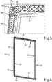
- Fig. 5 is an enlarged view of a section I in Fig. 4 shown.
- the support frame 9 comprises corner regions 9a, 9b, 9c and 9d.
- the truss structure 19 is formed on these corner regions 9a to 9d of the support frame 9 away inside and without interruption.
- this uninterrupted truss structure 19 ends below the corner region 9d and then opens at the offset the truss structure 19 of the vertical support frame part 14.
- At least one horizontally oriented support frame part 17 integrally at opposite ends 17a and 17b each have a corner region 9d and 9c and the truss structure 19 is formed in this horizontal support frame part 17 over the respective corner region 9d or 9c away.
- the horizontal support frame part 17 is formed to vertical support frame parts 14 and 16 out below the corner regions 9c and 9d each with a horizontal truss end wall 20 and 21 respectively. There offset towards the corners 9d and 9c down then ends in the horizontal support frame part 17 in these corner regions 9d and 9c without interruption and thus formed without modification truss structure 19th
- the support frame 9 is formed on the lower horizontal support frame part 15 with the corner portions 9a and 9b.
- Fig. 6 is a perspective view of the support frame 9 of the in Fig. 4 shown opposite side. As can be seen, the truss structure is not recognizable and virtually covered there.
- a seal 24 is formed on a inner edge 23, which thus represents an inner peripheral edge of the support frame 9, a seal 24 is formed.
- the seal 24 comprises at least one sealing lip.
- the carrier frame parts 14 to 17 have on the respective mutually facing edge sides.
- the support frame 9 also has an outer peripheral edge or outer edge 25.
- the seal 24 is non-destructively non-detachably formed on the inner edge 23.
- it can be injection-molded, in particular also be attached by a 2K injection molding, or by co-extrusion or by gluing.
- this seal 24 is mounted non-destructively releasably on the inner edge 23, in particular, for example, inserted or engaged.
- seal 24 is formed completely circumferentially and thus closed in circulation on the inner wheel 23 of the support frame 9.
- Fig. 7 is in a sectional view along the section line VII-VII in Fig. 2 the door 5 shown in partial view.
- the seal 24 is arranged on the support frame 9 and the in Fig. 7 shown carrier frame part 15 on the inner edge 23, the seal 24 is arranged.
- the seal 24 comprises a rear sealing lip 24a which is viewed in the depth direction (z-direction) of the household refrigerating appliance 1 and a further sealing lip 24b arranged at a distance from it further to the front.
- the two sealing lips 24a and 24b are oriented obliquely to the vacuum insulation element 8 and rearwardly to the interior 6 out when the door 5 is closed.
- the seal 24 is formed in cross-section U-shaped. It includes the sealing lips 24a and 24b as the free legs of the U-shape. These sealing lips 24a and 24b are also free cantilevered and formed cavity-free. They are in the mounted state of the door 5 at a narrow outer peripheral edge 8a of the vacuum insulation body or the vacuum insulation element 8 at. The two sealing lips 24a and 24b are arranged so as to extend in the same direction with respect to their oblique orientation.
- the door 5 is designed as a so-called full-vacuum door. This means that no further thermally insulating foam material is arranged in addition to the vacuum insulation element 8, which would at least partially surround the vacuum insulation element 8.
- the door 5 is thus explained as an embodiment of a wall according to the invention or an advantageous embodiment thereof. It may also be provided that, for example, one of the walls 4a to 4e designed accordingly. Such may be provided in addition to or instead of the corresponding design of the door 5.
- the back 7 of the vacuum insulation body 8 is the inwardly visible wall of the door 5.
- this inner shell 10 the inner end of the door 5, said inner shell 10 of a thermally deformed Plastic is formed.
- This preferably has low permeation values for air, water vapor and other gases.
- the outer shell 11 is also formed in particular from a thermally deformable plastic with low permeation values for the above-mentioned media, or it is formed from a film, which in particular also has metallized layers or at least one thin metal foil layer. This outer shell 11 is preferably adapted to the contour of the cover 18.
- the device 1 can be made smaller or the useful volume in the device 1 can be increased. Since such a useful volume is also included in the calculation of the energy efficiency class of such a household refrigerating appliance 1, a significant advantage is also achieved to that effect. Not least, the recyclability of the support material or filling material used in the insulation body is given by such a structure of a wall. Since accessibility is more difficult in comparison to embodiments in which such an element is fastened and surrounded by another foam due to the otherwise lacking mechanical positional fixation, such a wall, as indicated in the present application, is also significant here Advantage achieved. By a low assembly or disassembly effort of the insulation body with a few steps can be removed and the support material contained can be easily removed and processed for further use. By the support frame and a very simple interchangeability of the insulating body as such is possible, since in particular a nondestructive releasable connection between the support frame and the insulating body can be formed.
Landscapes
- Engineering & Computer Science (AREA)
- Chemical & Material Sciences (AREA)
- Combustion & Propulsion (AREA)
- Physics & Mathematics (AREA)
- Mechanical Engineering (AREA)
- Thermal Sciences (AREA)
- General Engineering & Computer Science (AREA)
- Refrigerator Housings (AREA)
Claims (13)
- Paroi (5, 4a à 4e) pour un appareil frigorifique (1) à usage domestique, comprenant au moins un corps d'isolation (8) thermique, le corps d'isolation (8) étant maintenu et entouré côté périphérique par un cadre de support (9) et le cadre de support (9) étant réalisé d'une seule pièce, caractérisée en ce que le cadre de support (9) présente côté intérieur, au moins en partie, une structure en treillis (19) et en ce que la structure en treillis (19) est réalisée intérieurement et sans interruption au-delà de zones en coin (9a à 9d) du cadre de support (9), de sorte que le modèle du treillis ne se modifie pas à ces transitions dans la zone en coin (9a à 9d) en comparaison à des zones éloignées de la zone en coin (9a à 9d) et se poursuit ainsi essentiellement de manière régulière.
- Paroi (5, 4a à 4e) selon la revendication 1, caractérisée en ce que le cadre de support (9) est réalisé de manière rectangulaire.
- Paroi (5, 4a à 4e) selon la revendication 1 ou 2, caractérisée en ce que le cadre de support (9) est réalisé en matière plastique.
- Paroi (5, 4a à 4e) selon la revendication 3, caractérisée en ce que le cadre de support (9) est une pièce moulée par injection.
- Paroi (5, 4a à 4e) selon la revendication 3 ou 4, caractérisée en ce que le cadre de support (9) est réalisé à partir d'au moins deux matières plastiques différentes.
- Paroi (5, 4a à 4e) selon l'une quelconque des revendications précédentes, caractérisée en ce qu'au moins un composant fonctionnel supplémentaire est disposé sur le cadre de support (9).
- Paroi (5, 4a à 4e) selon la revendication 6, caractérisée en ce qu'un composant fonctionnel est une charnière et/ou une unité de logement et/ou une pièce de renforcement.
- Paroi (5, 4a à 4e) selon l'une quelconque des revendications précédentes, caractérisée en ce qu'un élément de renforcement, notamment un élément de renforcement métallique est intégré, notamment intégré intérieurement, dans au moins une partie (14 à 17) du cadre de support (9).
- Paroi (5, 4a à 4e) selon l'une quelconque des revendications précédentes, caractérisée en ce qu'au moins une partie (15, 17) du cadre de support, orientée horizontalement, présente respectivement une zone en coin (9a à 9d), intégralement à des extrémités opposées (17a, 17b), et en ce que la structure en treillis (19) est réalisée dans cette partie (15, 17) horizontale du cadre de support au-delà des zones en coin (9a à 9d), et en ce que la partie (15, 17) horizontale du cadre de support présente en direction de parties (14, 16) verticales du cadre de support, en dessous des zones en coin (9a à 9d), une paroi terminale (20, 21) horizontale de treillis sur laquelle aboutit une structure en treillis (19) de la partie (14, 16) horizontale du cadre de support.
- Paroi (5, 4a à 4e) selon l'une quelconque des revendications précédentes, caractérisée en ce qu'une rainure (22) périphérique est réalisée sur un côté du cadre, dans laquelle un joint (13) est insérable.
- Paroi (5, 4a à 4e) selon l'une quelconque des revendications précédentes, caractérisée en ce que le corps d'isolation est un corps d'isolation sous vide (8).
- Paroi (5, 4a à 4e) selon l'une quelconque des revendications précédentes, caractérisée en ce qu'elle est une porte (5), notamment une porte à plein vide, pour l'appareil frigorifique (1) à usage domestique.
- Appareil frigorifique (1) à usage domestique comprenant au moins une paroi (5, 4a à 4e) selon l'une quelconque des revendications précédentes.
Applications Claiming Priority (2)
| Application Number | Priority Date | Filing Date | Title |
|---|---|---|---|
| DE102012223538.8A DE102012223538A1 (de) | 2012-12-18 | 2012-12-18 | Wandung für ein Haushaltskältegerät mit einem einstückigen Trägerrahmen für einen Isolationskörper sowie Haushaltskältegerät |
| PCT/EP2013/076306 WO2014095542A1 (fr) | 2012-12-18 | 2013-12-12 | Paroi pour un appareil de froid ménager, pourvue d'un cadre de support d'une seule pièce pour un corps isolant, et appareil de froid ménager |
Publications (2)
| Publication Number | Publication Date |
|---|---|
| EP2936012A1 EP2936012A1 (fr) | 2015-10-28 |
| EP2936012B1 true EP2936012B1 (fr) | 2017-04-26 |
Family
ID=49759312
Family Applications (1)
| Application Number | Title | Priority Date | Filing Date |
|---|---|---|---|
| EP13802993.9A Not-in-force EP2936012B1 (fr) | 2012-12-18 | 2013-12-12 | Paroi pour un appareil de froid ménager, pourvue d'un cadre de support d'une seule pièce pour un corps isolant, et appareil de froid ménager |
Country Status (5)
| Country | Link |
|---|---|
| EP (1) | EP2936012B1 (fr) |
| CN (1) | CN104870917B (fr) |
| DE (1) | DE102012223538A1 (fr) |
| PL (1) | PL2936012T3 (fr) |
| WO (1) | WO2014095542A1 (fr) |
Cited By (2)
| Publication number | Priority date | Publication date | Assignee | Title |
|---|---|---|---|---|
| US12264871B2 (en) | 2018-12-17 | 2025-04-01 | Whirlpool Corporation | Vacuum insulated door structure for an appliance incorporating a dispenser structure |
| EP4715292A1 (fr) * | 2024-09-23 | 2026-03-25 | BSH Hausgeräte GmbH | Appareil ménager doté d'un mécanisme de porte |
Families Citing this family (33)
| Publication number | Priority date | Publication date | Assignee | Title |
|---|---|---|---|---|
| US9140481B2 (en) | 2012-04-02 | 2015-09-22 | Whirlpool Corporation | Folded vacuum insulated structure |
| US9221210B2 (en) | 2012-04-11 | 2015-12-29 | Whirlpool Corporation | Method to create vacuum insulated cabinets for refrigerators |
| US9599392B2 (en) | 2014-02-24 | 2017-03-21 | Whirlpool Corporation | Folding approach to create a 3D vacuum insulated door from 2D flat vacuum insulation panels |
| US9689604B2 (en) | 2014-02-24 | 2017-06-27 | Whirlpool Corporation | Multi-section core vacuum insulation panels with hybrid barrier film envelope |
| US10052819B2 (en) | 2014-02-24 | 2018-08-21 | Whirlpool Corporation | Vacuum packaged 3D vacuum insulated door structure and method therefor using a tooling fixture |
| US9476633B2 (en) | 2015-03-02 | 2016-10-25 | Whirlpool Corporation | 3D vacuum panel and a folding approach to create the 3D vacuum panel from a 2D vacuum panel of non-uniform thickness |
| US10161669B2 (en) | 2015-03-05 | 2018-12-25 | Whirlpool Corporation | Attachment arrangement for vacuum insulated door |
| US9897370B2 (en) | 2015-03-11 | 2018-02-20 | Whirlpool Corporation | Self-contained pantry box system for insertion into an appliance |
| US9441779B1 (en) | 2015-07-01 | 2016-09-13 | Whirlpool Corporation | Split hybrid insulation structure for an appliance |
| US10222116B2 (en) | 2015-12-08 | 2019-03-05 | Whirlpool Corporation | Method and apparatus for forming a vacuum insulated structure for an appliance having a pressing mechanism incorporated within an insulation delivery system |
| US10041724B2 (en) | 2015-12-08 | 2018-08-07 | Whirlpool Corporation | Methods for dispensing and compacting insulation materials into a vacuum sealed structure |
| US11052579B2 (en) | 2015-12-08 | 2021-07-06 | Whirlpool Corporation | Method for preparing a densified insulation material for use in appliance insulated structure |
| US12508751B2 (en) | 2015-12-08 | 2025-12-30 | Whirlpool Corporation | Insulation compaction device and method for forming an insulated structure for an appliance |
| US10429125B2 (en) | 2015-12-08 | 2019-10-01 | Whirlpool Corporation | Insulation structure for an appliance having a uniformly mixed multi-component insulation material, and a method for even distribution of material combinations therein |
| US10422573B2 (en) | 2015-12-08 | 2019-09-24 | Whirlpool Corporation | Insulation structure for an appliance having a uniformly mixed multi-component insulation material, and a method for even distribution of material combinations therein |
| US10422569B2 (en) | 2015-12-21 | 2019-09-24 | Whirlpool Corporation | Vacuum insulated door construction |
| US9840042B2 (en) | 2015-12-22 | 2017-12-12 | Whirlpool Corporation | Adhesively secured vacuum insulated panels for refrigerators |
| US9752818B2 (en) | 2015-12-22 | 2017-09-05 | Whirlpool Corporation | Umbilical for pass through in vacuum insulated refrigerator structures |
| US10018406B2 (en) | 2015-12-28 | 2018-07-10 | Whirlpool Corporation | Multi-layer gas barrier materials for vacuum insulated structure |
| US10610985B2 (en) | 2015-12-28 | 2020-04-07 | Whirlpool Corporation | Multilayer barrier materials with PVD or plasma coating for vacuum insulated structure |
| US10030905B2 (en) | 2015-12-29 | 2018-07-24 | Whirlpool Corporation | Method of fabricating a vacuum insulated appliance structure |
| US10807298B2 (en) | 2015-12-29 | 2020-10-20 | Whirlpool Corporation | Molded gas barrier parts for vacuum insulated structure |
| US11247369B2 (en) | 2015-12-30 | 2022-02-15 | Whirlpool Corporation | Method of fabricating 3D vacuum insulated refrigerator structure having core material |
| US10712080B2 (en) | 2016-04-15 | 2020-07-14 | Whirlpool Corporation | Vacuum insulated refrigerator cabinet |
| EP3443284B1 (fr) | 2016-04-15 | 2020-11-18 | Whirlpool Corporation | Structure de réfrigérateur à isolation sous vide, dotée de caractéristiques tridimensionnelles |
| US11320193B2 (en) | 2016-07-26 | 2022-05-03 | Whirlpool Corporation | Vacuum insulated structure trim breaker |
| WO2018034665A1 (fr) | 2016-08-18 | 2018-02-22 | Whirlpool Corporation | Compartiment de machine pour une structure isolée sous vide |
| WO2018101954A1 (fr) | 2016-12-02 | 2018-06-07 | Whirlpool Corporation | Ensemble support de charnière |
| US10907888B2 (en) | 2018-06-25 | 2021-02-02 | Whirlpool Corporation | Hybrid pigmented hot stitched color liner system |
| US10907891B2 (en) | 2019-02-18 | 2021-02-02 | Whirlpool Corporation | Trim breaker for a structural cabinet that incorporates a structural glass contact surface |
| US11313611B2 (en) | 2019-05-01 | 2022-04-26 | Whirlpool Corporation | Construction method for vacuum insulated door |
| US11624547B2 (en) | 2021-06-14 | 2023-04-11 | Whirlpool Corporation | Bin attachment assembly for a trim breaker |
| TWI848788B (zh) * | 2023-08-07 | 2024-07-11 | 台灣松下電器股份有限公司 | 冰箱門裝置 |
Family Cites Families (12)
| Publication number | Priority date | Publication date | Assignee | Title |
|---|---|---|---|---|
| CN2184174Y (zh) * | 1993-12-22 | 1994-11-30 | 海尔集团青岛电冰柜总厂 | 搭接式组合柜口 |
| JPH0882474A (ja) * | 1994-09-12 | 1996-03-26 | Toshiba Corp | 真空断熱材 |
| CN101065628B (zh) * | 2004-11-29 | 2011-02-16 | 利勃海尔-家用电器奥克森豪森有限责任公司 | 冰箱或冷藏柜 |
| DE202004019865U1 (de) * | 2004-11-29 | 2006-04-06 | Liebherr-Hausgeräte Lienz Gmbh | Kühl- und/oder Gefriergerät |
| CN100565055C (zh) * | 2005-01-25 | 2009-12-02 | 利布赫尔家用器具奥克森豪森股份有限公司 | 一种冷藏和/或冷冻装置 |
| DE202005002231U1 (de) * | 2005-01-25 | 2006-06-08 | Liebherr-Hausgeräte Ochsenhausen GmbH | Kühl- und/oder Gefriergerät |
| EP2792976A1 (fr) * | 2007-09-26 | 2014-10-22 | BSH Bosch und Siemens Hausgeräte GmbH | Appareil de refroidissement doté d'un réceptacle pour un module électronique |
| DE102009002800A1 (de) * | 2009-05-04 | 2010-11-18 | BSH Bosch und Siemens Hausgeräte GmbH | Haushaltskältegerät und wärmeisolierende Wandung eines Haushaltskältegerätes |
| DE102009026658A1 (de) * | 2009-06-03 | 2010-12-09 | BSH Bosch und Siemens Hausgeräte GmbH | Haushaltskältegerät mit mindestens einer Versteifungsschiene |
| CN102032734B (zh) * | 2009-09-25 | 2014-06-04 | 博西华家用电器有限公司 | 家用电器 |
| DE102010040362A1 (de) | 2010-09-07 | 2012-03-08 | BSH Bosch und Siemens Hausgeräte GmbH | Gehäuse für ein Kältegerät |
| DE102011014302A1 (de) * | 2011-03-17 | 2012-09-20 | Liebherr-Hausgeräte Ochsenhausen GmbH | Türelement für ein Kühl- und/oder Gefriergerät |
-
2012
- 2012-12-18 DE DE102012223538.8A patent/DE102012223538A1/de not_active Withdrawn
-
2013
- 2013-12-12 CN CN201380066547.5A patent/CN104870917B/zh not_active Expired - Fee Related
- 2013-12-12 PL PL13802993T patent/PL2936012T3/pl unknown
- 2013-12-12 WO PCT/EP2013/076306 patent/WO2014095542A1/fr not_active Ceased
- 2013-12-12 EP EP13802993.9A patent/EP2936012B1/fr not_active Not-in-force
Non-Patent Citations (1)
| Title |
|---|
| None * |
Cited By (2)
| Publication number | Priority date | Publication date | Assignee | Title |
|---|---|---|---|---|
| US12264871B2 (en) | 2018-12-17 | 2025-04-01 | Whirlpool Corporation | Vacuum insulated door structure for an appliance incorporating a dispenser structure |
| EP4715292A1 (fr) * | 2024-09-23 | 2026-03-25 | BSH Hausgeräte GmbH | Appareil ménager doté d'un mécanisme de porte |
Also Published As
| Publication number | Publication date |
|---|---|
| CN104870917B (zh) | 2018-08-21 |
| EP2936012A1 (fr) | 2015-10-28 |
| CN104870917A (zh) | 2015-08-26 |
| WO2014095542A1 (fr) | 2014-06-26 |
| DE102012223538A1 (de) | 2014-06-18 |
| PL2936012T3 (pl) | 2017-09-29 |
Similar Documents
| Publication | Publication Date | Title |
|---|---|---|
| EP2936012B1 (fr) | Paroi pour un appareil de froid ménager, pourvue d'un cadre de support d'une seule pièce pour un corps isolant, et appareil de froid ménager | |
| EP2936023B1 (fr) | Cadre de support pour un corps isolant, pourvu d'un joint d'étanchéité sur sa paroi interne, et appareil ménager | |
| EP2936013B1 (fr) | Porte pour appareil ménager de production de froid pourvu d'un élément d'isolation sous vide à coques coulées, et appareil ménager de production de froid | |
| EP1222430B1 (fr) | Appareil refrigerant | |
| EP2203700B1 (fr) | Appareil frigorifique | |
| EP2732225B1 (fr) | Élément isolant sous vide | |
| DE102012223541A1 (de) | Vakuumisolationselement für ein Haushaltskältegerät mit einem Loch in der Hülle sowie Haushaltskältegerät mit einem Vakuumisolationselement | |
| DE10355137A1 (de) | Kältegerätegehäuse | |
| DE202008018347U1 (de) | Kältegerät | |
| EP2952839A1 (fr) | Porte pour un appareil menager et appareil menager | |
| EP2936014B1 (fr) | Appareil de froid ménager | |
| DE102014210473A1 (de) | Tür für ein Haushaltskältegerät mit einem Vakuumisolationselement sowie Haushaltskältegerät | |
| EP2993430A1 (fr) | Revetement pour un appareil menager et appareil menager dote d'un revetement | |
| WO2014095530A1 (fr) | Élément isolant sous vide pour un appareil de froid ménager, pourvu d'une partie encastrée magnétique située dans l'espace creux et d'une partie d'accouplement située sur la face externe, ainsi qu'appareil de froid ménager pourvu d'un élément isolant sous vide de ce type | |
| EP2936020B1 (fr) | Paroi pour un appareil de froid ménager pourvue d'une couche de finition présentant du polystyrène brillant et/ou des particules argentées, et appareil de froid ménager pourvu d'une telle paroi | |
| EP2936015B1 (fr) | Porte pour un appareil de froid ménager pourvue d'un renfoncement sur une face externe d'un élément isolant sous vide, et appareil de froid ménager pourvu d'une telle porte | |
| EP2936021B1 (fr) | Élément isolant sous vide pour un appareil de froid ménager, pourvu d'une saillie dans son enveloppe, appareil de froid ménager pourvu d'un élément isolant sous vide, et procédé de fabrication d'un élément isolant sous vide | |
| WO2014095636A1 (fr) | Paroi pour appareil ménager de froid pourvue d'un cadre de support carré pour un corps isolant thermique, et appareil ménager de froid | |
| EP3027983A1 (fr) | Procédé servant à fabriquer une paroi avec un élément de paroi, paroi ainsi qu'appareil frigorifique domestique | |
| DE102022200028A1 (de) | Haushaltskältegerät mit einem konfigurierbaren Gehäuse, sowie Verfahren zur Montage eines Haushaltskältegeräts | |
| DE102022200029A1 (de) | Haushaltskältegerät mit einem konfigurierbaren Montagemodul, sowie Verfahren zur Montage eines Haushaltskältegeräts | |
| WO2014195298A1 (fr) | Réfrigérateur domestique comportant une paroi à structure multicouche et procédé de fabrication d'une structure multicouche | |
| EP2645026B1 (fr) | Appareil de réfrigération et/ou de congélation | |
| EP2746704B1 (fr) | Appareil frigorifique ménager doté d'une fente d'aération non rectiligne entre une porte d'un compartiment de congélation et une porte d'un compartiment de réfrigération adjacent | |
| EP2667127A2 (fr) | Appareil frigorifique, en particulier appareil ménager |
Legal Events
| Date | Code | Title | Description |
|---|---|---|---|
| PUAI | Public reference made under article 153(3) epc to a published international application that has entered the european phase |
Free format text: ORIGINAL CODE: 0009012 |
|
| 17P | Request for examination filed |
Effective date: 20150720 |
|
| AK | Designated contracting states |
Kind code of ref document: A1 Designated state(s): AL AT BE BG CH CY CZ DE DK EE ES FI FR GB GR HR HU IE IS IT LI LT LU LV MC MK MT NL NO PL PT RO RS SE SI SK SM TR |
|
| AX | Request for extension of the european patent |
Extension state: BA ME |
|
| DAX | Request for extension of the european patent (deleted) | ||
| GRAP | Despatch of communication of intention to grant a patent |
Free format text: ORIGINAL CODE: EPIDOSNIGR1 |
|
| INTG | Intention to grant announced |
Effective date: 20161213 |
|
| GRAS | Grant fee paid |
Free format text: ORIGINAL CODE: EPIDOSNIGR3 |
|
| GRAA | (expected) grant |
Free format text: ORIGINAL CODE: 0009210 |
|
| AK | Designated contracting states |
Kind code of ref document: B1 Designated state(s): AL AT BE BG CH CY CZ DE DK EE ES FI FR GB GR HR HU IE IS IT LI LT LU LV MC MK MT NL NO PL PT RO RS SE SI SK SM TR |
|
| REG | Reference to a national code |
Ref country code: GB Ref legal event code: FG4D Free format text: NOT ENGLISH |
|
| REG | Reference to a national code |
Ref country code: CH Ref legal event code: EP |
|
| REG | Reference to a national code |
Ref country code: AT Ref legal event code: REF Ref document number: 888249 Country of ref document: AT Kind code of ref document: T Effective date: 20170515 |
|
| REG | Reference to a national code |
Ref country code: IE Ref legal event code: FG4D Free format text: LANGUAGE OF EP DOCUMENT: GERMAN |
|
| REG | Reference to a national code |
Ref country code: DE Ref legal event code: R096 Ref document number: 502013007102 Country of ref document: DE |
|
| REG | Reference to a national code |
Ref country code: NL Ref legal event code: MP Effective date: 20170426 |
|
| REG | Reference to a national code |
Ref country code: LT Ref legal event code: MG4D |
|
| PG25 | Lapsed in a contracting state [announced via postgrant information from national office to epo] |
Ref country code: NL Free format text: LAPSE BECAUSE OF FAILURE TO SUBMIT A TRANSLATION OF THE DESCRIPTION OR TO PAY THE FEE WITHIN THE PRESCRIBED TIME-LIMIT Effective date: 20170426 |
|
| PG25 | Lapsed in a contracting state [announced via postgrant information from national office to epo] |
Ref country code: HR Free format text: LAPSE BECAUSE OF FAILURE TO SUBMIT A TRANSLATION OF THE DESCRIPTION OR TO PAY THE FEE WITHIN THE PRESCRIBED TIME-LIMIT Effective date: 20170426 Ref country code: GR Free format text: LAPSE BECAUSE OF FAILURE TO SUBMIT A TRANSLATION OF THE DESCRIPTION OR TO PAY THE FEE WITHIN THE PRESCRIBED TIME-LIMIT Effective date: 20170727 Ref country code: LT Free format text: LAPSE BECAUSE OF FAILURE TO SUBMIT A TRANSLATION OF THE DESCRIPTION OR TO PAY THE FEE WITHIN THE PRESCRIBED TIME-LIMIT Effective date: 20170426 Ref country code: FI Free format text: LAPSE BECAUSE OF FAILURE TO SUBMIT A TRANSLATION OF THE DESCRIPTION OR TO PAY THE FEE WITHIN THE PRESCRIBED TIME-LIMIT Effective date: 20170426 Ref country code: NO Free format text: LAPSE BECAUSE OF FAILURE TO SUBMIT A TRANSLATION OF THE DESCRIPTION OR TO PAY THE FEE WITHIN THE PRESCRIBED TIME-LIMIT Effective date: 20170726 Ref country code: ES Free format text: LAPSE BECAUSE OF FAILURE TO SUBMIT A TRANSLATION OF THE DESCRIPTION OR TO PAY THE FEE WITHIN THE PRESCRIBED TIME-LIMIT Effective date: 20170426 |
|
| PG25 | Lapsed in a contracting state [announced via postgrant information from national office to epo] |
Ref country code: IS Free format text: LAPSE BECAUSE OF FAILURE TO SUBMIT A TRANSLATION OF THE DESCRIPTION OR TO PAY THE FEE WITHIN THE PRESCRIBED TIME-LIMIT Effective date: 20170826 Ref country code: BG Free format text: LAPSE BECAUSE OF FAILURE TO SUBMIT A TRANSLATION OF THE DESCRIPTION OR TO PAY THE FEE WITHIN THE PRESCRIBED TIME-LIMIT Effective date: 20170726 Ref country code: RS Free format text: LAPSE BECAUSE OF FAILURE TO SUBMIT A TRANSLATION OF THE DESCRIPTION OR TO PAY THE FEE WITHIN THE PRESCRIBED TIME-LIMIT Effective date: 20170426 Ref country code: LV Free format text: LAPSE BECAUSE OF FAILURE TO SUBMIT A TRANSLATION OF THE DESCRIPTION OR TO PAY THE FEE WITHIN THE PRESCRIBED TIME-LIMIT Effective date: 20170426 Ref country code: SE Free format text: LAPSE BECAUSE OF FAILURE TO SUBMIT A TRANSLATION OF THE DESCRIPTION OR TO PAY THE FEE WITHIN THE PRESCRIBED TIME-LIMIT Effective date: 20170426 |
|
| REG | Reference to a national code |
Ref country code: DE Ref legal event code: R097 Ref document number: 502013007102 Country of ref document: DE |
|
| PG25 | Lapsed in a contracting state [announced via postgrant information from national office to epo] |
Ref country code: RO Free format text: LAPSE BECAUSE OF FAILURE TO SUBMIT A TRANSLATION OF THE DESCRIPTION OR TO PAY THE FEE WITHIN THE PRESCRIBED TIME-LIMIT Effective date: 20170426 Ref country code: DK Free format text: LAPSE BECAUSE OF FAILURE TO SUBMIT A TRANSLATION OF THE DESCRIPTION OR TO PAY THE FEE WITHIN THE PRESCRIBED TIME-LIMIT Effective date: 20170426 Ref country code: EE Free format text: LAPSE BECAUSE OF FAILURE TO SUBMIT A TRANSLATION OF THE DESCRIPTION OR TO PAY THE FEE WITHIN THE PRESCRIBED TIME-LIMIT Effective date: 20170426 Ref country code: SK Free format text: LAPSE BECAUSE OF FAILURE TO SUBMIT A TRANSLATION OF THE DESCRIPTION OR TO PAY THE FEE WITHIN THE PRESCRIBED TIME-LIMIT Effective date: 20170426 Ref country code: CZ Free format text: LAPSE BECAUSE OF FAILURE TO SUBMIT A TRANSLATION OF THE DESCRIPTION OR TO PAY THE FEE WITHIN THE PRESCRIBED TIME-LIMIT Effective date: 20170426 |
|
| PGFP | Annual fee paid to national office [announced via postgrant information from national office to epo] |
Ref country code: TR Payment date: 20171211 Year of fee payment: 5 |
|
| PG25 | Lapsed in a contracting state [announced via postgrant information from national office to epo] |
Ref country code: SM Free format text: LAPSE BECAUSE OF FAILURE TO SUBMIT A TRANSLATION OF THE DESCRIPTION OR TO PAY THE FEE WITHIN THE PRESCRIBED TIME-LIMIT Effective date: 20170426 |
|
| PLBE | No opposition filed within time limit |
Free format text: ORIGINAL CODE: 0009261 |
|
| STAA | Information on the status of an ep patent application or granted ep patent |
Free format text: STATUS: NO OPPOSITION FILED WITHIN TIME LIMIT |
|
| 26N | No opposition filed |
Effective date: 20180129 |
|
| PG25 | Lapsed in a contracting state [announced via postgrant information from national office to epo] |
Ref country code: SI Free format text: LAPSE BECAUSE OF FAILURE TO SUBMIT A TRANSLATION OF THE DESCRIPTION OR TO PAY THE FEE WITHIN THE PRESCRIBED TIME-LIMIT Effective date: 20170426 |
|
| REG | Reference to a national code |
Ref country code: CH Ref legal event code: PL |
|
| GBPC | Gb: european patent ceased through non-payment of renewal fee |
Effective date: 20171212 |
|
| REG | Reference to a national code |
Ref country code: IE Ref legal event code: MM4A |
|
| PG25 | Lapsed in a contracting state [announced via postgrant information from national office to epo] |
Ref country code: LU Free format text: LAPSE BECAUSE OF NON-PAYMENT OF DUE FEES Effective date: 20171212 Ref country code: MT Free format text: LAPSE BECAUSE OF FAILURE TO SUBMIT A TRANSLATION OF THE DESCRIPTION OR TO PAY THE FEE WITHIN THE PRESCRIBED TIME-LIMIT Effective date: 20170426 |
|
| REG | Reference to a national code |
Ref country code: FR Ref legal event code: ST Effective date: 20180831 |
|
| REG | Reference to a national code |
Ref country code: BE Ref legal event code: MM Effective date: 20171231 |
|
| PG25 | Lapsed in a contracting state [announced via postgrant information from national office to epo] |
Ref country code: IE Free format text: LAPSE BECAUSE OF NON-PAYMENT OF DUE FEES Effective date: 20171212 Ref country code: FR Free format text: LAPSE BECAUSE OF NON-PAYMENT OF DUE FEES Effective date: 20180102 |
|
| PG25 | Lapsed in a contracting state [announced via postgrant information from national office to epo] |
Ref country code: CH Free format text: LAPSE BECAUSE OF NON-PAYMENT OF DUE FEES Effective date: 20171231 Ref country code: GB Free format text: LAPSE BECAUSE OF NON-PAYMENT OF DUE FEES Effective date: 20171212 Ref country code: LI Free format text: LAPSE BECAUSE OF NON-PAYMENT OF DUE FEES Effective date: 20171231 Ref country code: BE Free format text: LAPSE BECAUSE OF NON-PAYMENT OF DUE FEES Effective date: 20171231 |
|
| PGFP | Annual fee paid to national office [announced via postgrant information from national office to epo] |
Ref country code: PL Payment date: 20181204 Year of fee payment: 6 |
|
| PGFP | Annual fee paid to national office [announced via postgrant information from national office to epo] |
Ref country code: IT Payment date: 20181218 Year of fee payment: 6 |
|
| PGFP | Annual fee paid to national office [announced via postgrant information from national office to epo] |
Ref country code: DE Payment date: 20181231 Year of fee payment: 6 |
|
| PG25 | Lapsed in a contracting state [announced via postgrant information from national office to epo] |
Ref country code: MC Free format text: LAPSE BECAUSE OF FAILURE TO SUBMIT A TRANSLATION OF THE DESCRIPTION OR TO PAY THE FEE WITHIN THE PRESCRIBED TIME-LIMIT Effective date: 20170426 Ref country code: HU Free format text: LAPSE BECAUSE OF FAILURE TO SUBMIT A TRANSLATION OF THE DESCRIPTION OR TO PAY THE FEE WITHIN THE PRESCRIBED TIME-LIMIT; INVALID AB INITIO Effective date: 20131212 |
|
| PG25 | Lapsed in a contracting state [announced via postgrant information from national office to epo] |
Ref country code: CY Free format text: LAPSE BECAUSE OF FAILURE TO SUBMIT A TRANSLATION OF THE DESCRIPTION OR TO PAY THE FEE WITHIN THE PRESCRIBED TIME-LIMIT Effective date: 20170426 |
|
| PG25 | Lapsed in a contracting state [announced via postgrant information from national office to epo] |
Ref country code: MK Free format text: LAPSE BECAUSE OF FAILURE TO SUBMIT A TRANSLATION OF THE DESCRIPTION OR TO PAY THE FEE WITHIN THE PRESCRIBED TIME-LIMIT Effective date: 20170426 |
|
| REG | Reference to a national code |
Ref country code: AT Ref legal event code: MM01 Ref document number: 888249 Country of ref document: AT Kind code of ref document: T Effective date: 20181212 |
|
| PG25 | Lapsed in a contracting state [announced via postgrant information from national office to epo] |
Ref country code: AT Free format text: LAPSE BECAUSE OF NON-PAYMENT OF DUE FEES Effective date: 20181212 |
|
| PG25 | Lapsed in a contracting state [announced via postgrant information from national office to epo] |
Ref country code: PT Free format text: LAPSE BECAUSE OF FAILURE TO SUBMIT A TRANSLATION OF THE DESCRIPTION OR TO PAY THE FEE WITHIN THE PRESCRIBED TIME-LIMIT Effective date: 20170426 |
|
| REG | Reference to a national code |
Ref country code: DE Ref legal event code: R119 Ref document number: 502013007102 Country of ref document: DE |
|
| PG25 | Lapsed in a contracting state [announced via postgrant information from national office to epo] |
Ref country code: AL Free format text: LAPSE BECAUSE OF FAILURE TO SUBMIT A TRANSLATION OF THE DESCRIPTION OR TO PAY THE FEE WITHIN THE PRESCRIBED TIME-LIMIT Effective date: 20170426 |
|
| PG25 | Lapsed in a contracting state [announced via postgrant information from national office to epo] |
Ref country code: DE Free format text: LAPSE BECAUSE OF NON-PAYMENT OF DUE FEES Effective date: 20200701 Ref country code: IT Free format text: LAPSE BECAUSE OF NON-PAYMENT OF DUE FEES Effective date: 20191212 |
|
| PG25 | Lapsed in a contracting state [announced via postgrant information from national office to epo] |
Ref country code: PL Free format text: LAPSE BECAUSE OF NON-PAYMENT OF DUE FEES Effective date: 20191212 |
|
| PG25 | Lapsed in a contracting state [announced via postgrant information from national office to epo] |
Ref country code: TR Free format text: LAPSE BECAUSE OF NON-PAYMENT OF DUE FEES Effective date: 20191212 |