EP2936071B1 - Système et procédé pour compenser des distorsions de fréquence et des effets induits par la polarisation dans des systèmes optiques - Google Patents
Système et procédé pour compenser des distorsions de fréquence et des effets induits par la polarisation dans des systèmes optiques Download PDFInfo
- Publication number
- EP2936071B1 EP2936071B1 EP13821815.1A EP13821815A EP2936071B1 EP 2936071 B1 EP2936071 B1 EP 2936071B1 EP 13821815 A EP13821815 A EP 13821815A EP 2936071 B1 EP2936071 B1 EP 2936071B1
- Authority
- EP
- European Patent Office
- Prior art keywords
- wavelength
- polarization
- sweep
- fine
- optical
- Prior art date
- Legal status (The legal status is an assumption and is not a legal conclusion. Google has not performed a legal analysis and makes no representation as to the accuracy of the status listed.)
- Active
Links
Images





Classifications
-
- H—ELECTRICITY
- H01—ELECTRIC ELEMENTS
- H01S—DEVICES USING THE PROCESS OF LIGHT AMPLIFICATION BY STIMULATED EMISSION OF RADIATION [LASER] TO AMPLIFY OR GENERATE LIGHT; DEVICES USING STIMULATED EMISSION OF ELECTROMAGNETIC RADIATION IN WAVE RANGES OTHER THAN OPTICAL
- H01S5/00—Semiconductor lasers
- H01S5/06—Arrangements for controlling the laser output parameters, e.g. by operating on the active medium
- H01S5/068—Stabilisation of laser output parameters
-
- H—ELECTRICITY
- H01—ELECTRIC ELEMENTS
- H01S—DEVICES USING THE PROCESS OF LIGHT AMPLIFICATION BY STIMULATED EMISSION OF RADIATION [LASER] TO AMPLIFY OR GENERATE LIGHT; DEVICES USING STIMULATED EMISSION OF ELECTROMAGNETIC RADIATION IN WAVE RANGES OTHER THAN OPTICAL
- H01S5/00—Semiconductor lasers
- H01S5/06—Arrangements for controlling the laser output parameters, e.g. by operating on the active medium
- H01S5/068—Stabilisation of laser output parameters
- H01S5/0683—Stabilisation of laser output parameters by monitoring the optical output parameters
- H01S5/0687—Stabilising the frequency of the laser
-
- G—PHYSICS
- G01—MEASURING; TESTING
- G01D—MEASURING NOT SPECIALLY ADAPTED FOR A SPECIFIC VARIABLE; ARRANGEMENTS FOR MEASURING TWO OR MORE VARIABLES NOT COVERED IN A SINGLE OTHER SUBCLASS; TARIFF METERING APPARATUS; MEASURING OR TESTING NOT OTHERWISE PROVIDED FOR
- G01D18/00—Testing or calibrating apparatus or arrangements provided for in groups G01D1/00 - G01D15/00
-
- G—PHYSICS
- G01—MEASURING; TESTING
- G01D—MEASURING NOT SPECIALLY ADAPTED FOR A SPECIFIC VARIABLE; ARRANGEMENTS FOR MEASURING TWO OR MORE VARIABLES NOT COVERED IN A SINGLE OTHER SUBCLASS; TARIFF METERING APPARATUS; MEASURING OR TESTING NOT OTHERWISE PROVIDED FOR
- G01D5/00—Mechanical means for transferring the output of a sensing member; Means for converting the output of a sensing member to another variable where the form or nature of the sensing member does not constrain the means for converting; Transducers not specially adapted for a specific variable
- G01D5/26—Mechanical means for transferring the output of a sensing member; Means for converting the output of a sensing member to another variable where the form or nature of the sensing member does not constrain the means for converting; Transducers not specially adapted for a specific variable characterised by optical transfer means, i.e. using infrared, visible, or ultraviolet light
- G01D5/268—Mechanical means for transferring the output of a sensing member; Means for converting the output of a sensing member to another variable where the form or nature of the sensing member does not constrain the means for converting; Transducers not specially adapted for a specific variable characterised by optical transfer means, i.e. using infrared, visible, or ultraviolet light using optical fibres
-
- H—ELECTRICITY
- H01—ELECTRIC ELEMENTS
- H01S—DEVICES USING THE PROCESS OF LIGHT AMPLIFICATION BY STIMULATED EMISSION OF RADIATION [LASER] TO AMPLIFY OR GENERATE LIGHT; DEVICES USING STIMULATED EMISSION OF ELECTROMAGNETIC RADIATION IN WAVE RANGES OTHER THAN OPTICAL
- H01S3/00—Lasers, i.e. devices using stimulated emission of electromagnetic radiation in the infrared, visible or ultraviolet wave range
- H01S3/10—Controlling the intensity, frequency, phase, polarisation or direction of the emitted radiation, e.g. switching, gating, modulating or demodulating
- H01S3/13—Stabilisation of laser output parameters, e.g. frequency or amplitude
- H01S3/1303—Stabilisation of laser output parameters, e.g. frequency or amplitude by using a passive reference, e.g. absorption cell
-
- H—ELECTRICITY
- H01—ELECTRIC ELEMENTS
- H01S—DEVICES USING THE PROCESS OF LIGHT AMPLIFICATION BY STIMULATED EMISSION OF RADIATION [LASER] TO AMPLIFY OR GENERATE LIGHT; DEVICES USING STIMULATED EMISSION OF ELECTROMAGNETIC RADIATION IN WAVE RANGES OTHER THAN OPTICAL
- H01S5/00—Semiconductor lasers
- H01S5/0014—Measuring characteristics or properties thereof
- H01S5/0021—Degradation or life time measurements
-
- H—ELECTRICITY
- H01—ELECTRIC ELEMENTS
- H01S—DEVICES USING THE PROCESS OF LIGHT AMPLIFICATION BY STIMULATED EMISSION OF RADIATION [LASER] TO AMPLIFY OR GENERATE LIGHT; DEVICES USING STIMULATED EMISSION OF ELECTROMAGNETIC RADIATION IN WAVE RANGES OTHER THAN OPTICAL
- H01S5/00—Semiconductor lasers
- H01S5/06—Arrangements for controlling the laser output parameters, e.g. by operating on the active medium
- H01S5/068—Stabilisation of laser output parameters
- H01S5/06804—Stabilisation of laser output parameters by monitoring an external parameter, e.g. temperature
-
- H—ELECTRICITY
- H01—ELECTRIC ELEMENTS
- H01S—DEVICES USING THE PROCESS OF LIGHT AMPLIFICATION BY STIMULATED EMISSION OF RADIATION [LASER] TO AMPLIFY OR GENERATE LIGHT; DEVICES USING STIMULATED EMISSION OF ELECTROMAGNETIC RADIATION IN WAVE RANGES OTHER THAN OPTICAL
- H01S5/00—Semiconductor lasers
- H01S5/06—Arrangements for controlling the laser output parameters, e.g. by operating on the active medium
- H01S5/068—Stabilisation of laser output parameters
- H01S5/06817—Noise reduction
-
- H—ELECTRICITY
- H01—ELECTRIC ELEMENTS
- H01S—DEVICES USING THE PROCESS OF LIGHT AMPLIFICATION BY STIMULATED EMISSION OF RADIATION [LASER] TO AMPLIFY OR GENERATE LIGHT; DEVICES USING STIMULATED EMISSION OF ELECTROMAGNETIC RADIATION IN WAVE RANGES OTHER THAN OPTICAL
- H01S5/00—Semiconductor lasers
- H01S5/06—Arrangements for controlling the laser output parameters, e.g. by operating on the active medium
- H01S5/068—Stabilisation of laser output parameters
- H01S5/06821—Stabilising other output parameters than intensity or frequency, e.g. phase, polarisation or far-fields
-
- H—ELECTRICITY
- H01—ELECTRIC ELEMENTS
- H01S—DEVICES USING THE PROCESS OF LIGHT AMPLIFICATION BY STIMULATED EMISSION OF RADIATION [LASER] TO AMPLIFY OR GENERATE LIGHT; DEVICES USING STIMULATED EMISSION OF ELECTROMAGNETIC RADIATION IN WAVE RANGES OTHER THAN OPTICAL
- H01S5/00—Semiconductor lasers
- H01S5/10—Construction or shape of the optical resonator, e.g. extended or external cavity, coupled cavities, bent-guide, varying width, thickness or composition of the active region
- H01S5/1092—Multi-wavelength lasing
Definitions
- the invention relates to a system and method to compensate for instantaneous frequency noise and/or sweep nonlinearities induced by frequency swept tunable lasers used in optical interrogator/characterization systems.
- the tunable laser in the interrogator system must be swept in a linear fashion in order to measure back a linear response of the FBG.
- the tuneable source is characterized to generate a linear sweep.
- the interrogator system disclosed in US7,649,917 assigned to Intune Networks Limited, provides a tunable laser that scans linearly across all segments that are used to generate a quasi linear sweep over a full operational band (e.g. C/L-bands).
- the quasi linear sweep was based on stitching multiple overlapping mini-sweeps (segments) using a periodic wavelength reference e.g. Etalon to guarantee full coverage.
- the Etalons used are typically 25GHz and minimum of 25GHz was required to have a common Etalon for stitching, which results in a limit on the maximum achievable sweep rate.
- a wavelength referencing and polarization mitigation system for use with an optical wavelength tunable source, said system comprising at least one coarse reference wavelength section characterised by a fine wavelength reference section adapted for measuring sensor characteristics or characterizing wavelength dependent optical devices.
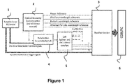
- the invention provides a system where a fine wavelength reference is introduced in the wavelength reference system in addition to the other references (for example an Athermal Etalon (coarse reference) and Gas cell wavelength reference (absolute reference)).
- This fine wavelength reference is an optical device with a periodic wavelength response such as a Mach-Zehnder interferometer (MZI) which can have a small free spectral range (FSR) compared to the Etalon reference.
- MZI Mach-Zehnder interferometer
- FSR free spectral range
- the MZI can be implemented using different technologies (e.g. fibre based, free-space optics, integrated optical circuits PLC, or built with polarization maintaining (PM) fibre and a polarizer).
- the fine reference section is adapted for pre-compensating nonlinearities in the optical wavelength tunable source.
- the reference section comprises at least one gas cell reference adapted to provide absolute frequency information.
- an active polarization control device adapted to control the state of polarization in an asynchronous or synchronous fashion to mitigate for polarization induced wavelength shifts in interrogated sensors/filters.
- An extra high speed polarization scrambler/switch can replace the PM fibre based passive polarization scrambler or added to the system.
- Adding the MZI and polarization scrambler/switch improves the accuracy of the results and reduces the polarization sensitivity of the optical fibre sensors/filters interrogated (e.g. FBGs) by the laser(s) in the system.
- the optical fibre sensors/filters interrogated e.g. FBGs
- Extensions to the system can also be accommodated through the use of multiple lasers sweeping in parallel at different wavelengths and sharing the MZI reference and polarization scrambler/switch.
- the MZI reference can also be used to calibrate the laser to pre-compensate for any non-linearity in the sweep.
- an optical assembly including the reference section is used to provide wavelength (absolute/relative) and power reference signals to the receiver section.
- the Interrogator optical splitter section is used to support multiple fibre channels containing optical sensors or devices.
- the Interrogator reference system includes a power reference to compensate for any power variations in the output of the tunable laser.
- the Interrogator reference system includes one or more Gas cell reference to provide absolute frequency information.
- an active polarization control device is used to control the state of polarization in an asynchronous (active polarization scrambler) or synchronous (active polarization switch) manner to mitigate for polarization induced wavelength shifts due to the optical sensors polarization dependency.
- the system is improved by increasing the number of tunable lasers/swept sources used for sweeping so as to further increase the flexibility and speed at which the sensors are measured.
- the invention provides a frequency compensation and polarization mitigation system used in a tunable laser based optical interrogator measuring sensor characteristics obtained from an array of optical sensors.
- Figure 5 shows two different implementations, (a) using PM couplers spliced together with a certain path length different to form an interferometer, and (b) using a piece of PM fibre with a certain length (differential group delay) to construct an interferometer when the input is spliced with a 45 degree angle and the output is connected to a polarizer.
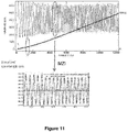
- the MZI periods (defined by a free spectral range (FSR) smaller than the Etalon peak spacing and having zero-crossing points or peak-through spacing defined by FSR/2) are used. Since the number of MZI periods between two Etalon peaks is constant, this information enables the measurement of the start and stop wavelength of each sweep segment by using the Etalon peak information as an absolute wavelength reference and the MZI information as a relative offset wavelength reference compared to the Etalon peak location. As an example in Figure 7 the spacing between two Etalon peaks is equivalent to three MZI periods (or 6 MZI crossing points), therefore the wavelength end point of the 1 st sweep segment is equivalent to its third Etalon peak location plus two MZI periods (4 MZI crossings).
- FSR free spectral range
- a passive polarization maintaining birefringent fibre is used as a continuous waveplate to scramble the polarization state of the laser source.
- the passive scrambler is constructed using a piece of PM fibre where the input is spliced with the laser output with a 45 degree angle between the birefringence axes and the other end is connected to a PM coupler/splitter with one output connected to the splitter section for the FBG sensors.
- the above approach allows the polarisation and wavelength to be sampled at the same time, and having both effects sampled accordingly in lock step with each other.
- the rotation of the polarisation becomes wavelength dependent and the polarisation state at the output of the passive scrambler rotates in proportion to the wavelength and the length of the PM fiber.
- the embodiments in the invention described with reference to the drawings comprise a computer apparatus and/or processes performed in a computer apparatus.
- the invention also extends to computer programs, particularly computer programs stored on or in a carrier adapted to bring the invention into practice.
- the program may be in the form of source code, object code, or a code intermediate source and object code, such as in partially compiled form or in any other form suitable for use in the implementation of the method according to the invention.
- the carrier may comprise a storage medium such as ROM, e.g. CD ROM, or magnetic recording medium, e.g. a floppy disk or hard disk.
- the carrier may be an electrical or optical signal which may be transmitted via an electrical or an optical cable or by radio or other means.
Landscapes
- Physics & Mathematics (AREA)
- General Physics & Mathematics (AREA)
- Electromagnetism (AREA)
- Optics & Photonics (AREA)
- Condensed Matter Physics & Semiconductors (AREA)
- Engineering & Computer Science (AREA)
- Plasma & Fusion (AREA)
- Optical Communication System (AREA)
- Optical Modulation, Optical Deflection, Nonlinear Optics, Optical Demodulation, Optical Logic Elements (AREA)
- Lasers (AREA)
Claims (14)
- Un système d'atténuation de polarisation et de référencement de longueur d'onde destiné à une utilisation avec une source laser accordable en longueur d'onde optique possédant un nombre de segments de balayage différents, ledit système comprenant :au moins une section de longueur d'onde de référence grossière stable comprenant un dispositif optique adapté de façon à fournir un signal de référence de longueur d'onde grossière destiné à la génération d'au moins un marqueur de longueur d'onde stable à l'intérieur d'un segment de balayage,une section de référence de longueur d'onde fine adaptée à la mesure d'une réponse en longueur d'onde périodique d'un dispositif optique, la section de référence de longueur d'onde fine comprenant un dispositif optique adapté de façon à fournir un signal de référence de longueur d'onde périodique fine destiné à la génération d'une pluralité de marqueurs de longueur d'onde fine à l'intérieur d'un segment de balayage possédant un décalage par rapport au marqueur de longueur d'onde stable, où le signal de référence de longueur d'onde fine possède une plage spectrale libre plus petite que l'espacement entre des marqueurs de longueur d'onde stable du signal de référence de longueur d'onde grossière, etun moyen de raccordement les uns aux autres de segments de balayage contigus de la source laser accordable au moyen de la pluralité de marqueurs de longueur d'onde fine référencés vis-à-vis du au moins un marqueur de longueur d'onde stable en tant que point de raccordement de sorte que le chevauchement requis minimal entre segments de balayage soit réduit.
- Un système selon la Revendication 1 où le au moins un marqueur de longueur d'onde stable comprend une réponse en longueur d'onde distincte stable sélectionnée parmi au moins un élément parmi pics, creux ou pentes détectés.
- Un système selon l'une quelconque des Revendications précédentes où le dispositif optique de la section de référence de longueur d'onde fine est adapté de façon à fournir une correction de fréquence des segments de balayage générés de source accordable en termes de bruit de fréquence instantané et de non-linéarité de balayage.
- Le système selon l'une quelconque des Revendications précédentes comprenant un étalon destiné à la fourniture du signal de référence de longueur d'onde grossière et un interféromètre de Mach-Zehnder destiné à la fourniture du signal de référence de longueur d'onde fine.
- Le système selon la Revendication 1 comprenant un moyen de mesure d'un espacement entre les points de passage par zéro du signal de référence de longueur d'onde périodique fine de façon à fournir des données de commande pour la source accordable de longueur d'onde.
- Le système selon l'une quelconque des Revendications 1 à 5 comprenant un moyen de détection de discontinuités quelconques dans la fréquence périodique du dispositif optique où des discontinuités détectées dans la fréquence périodique fournissent des données de commande pour la source accordable de longueur d'onde et où le système est configuré de façon à éviter des sauts de mode dans le balayage.
- Le système selon la Revendication 6 où les données de commande fournissent un moyen de recalibrage de points opérationnels de la source accordable de longueur d'onde optique.
- Un système selon l'une quelconque des Revendications précédentes où la section de référence de longueur d'onde fine est adaptée de façon à précompenser des non-linéarités dans le balayage généré de la source accordable de longueur d'onde optique.
- Un système selon l'une quelconque des Revendications précédentes où une section de référence absolue comprend au moins une référence de cellule à gaz adaptée de façon à fournir des informations de fréquence absolue.
- Un système selon la Revendication 1 où le dispositif optique de la section de référence de longueur d'onde fine comprend un interféromètre de Mach-Zehnder (MZI) et un brouilleur de polarisation.
- Le système selon la Revendication 10 où le MZI et le brouilleur comprennent au moins une fibre de maintien de polarisation configurée avec un angle de lancement de polarisation souhaité et une longueur adaptée de façon à fournir des informations de fréquence et à atténuer des effets induits par la polarisation dans les capteurs et/ou les filtres par la modification de l'état de polarisation de la sortie laser de manière synchrone avec des croisements, pics et creux de MZI détectés.
- Un système selon l'une quelconque des Revendications précédentes comprenant un dispositif de commande de polarisation active adapté de façon à commander l'état de polarisation de manière asynchrone ou synchrone de façon à atténuer des décalages de longueur d'onde induits par la polarisation dans des capteurs et/ou des filtres interrogés et/ou où la section de commande de polarisation est adaptée de façon à recevoir un signal de commande électrique à partir de la source accordable, et/ou
où la source accordable de longueur d'onde optique comprend un laser accordable ou une source de balayage de longueur d'onde. - Un procédé de référencement de longueur d'onde et d'atténuation de polarisation destiné à une utilisation avec une source laser accordable en longueur d'onde optique possédant un nombre de segments de balayage différents, ledit procédé comprenant les opérations suivantes :la sélection d'au moins une section de longueur d'onde de référence grossière stable comprenant un dispositif optique adapté de façon à fournir un signal de référence de longueur d'onde grossière destiné à la génération d'au moins un marqueur de longueur d'onde stable à l'intérieur d'un segment de balayage,la sélection d'une section de référence de longueur d'onde fine et son adaptation à la mesure d'une réponse en longueur d'onde périodique d'un dispositif optique, la section de référence de longueur d'onde fine comprenant un dispositif optique adapté de façon à fournir un signal de référence de longueur d'onde périodique fine destiné à la génération d'une pluralité de marqueurs de longueur d'onde fine à l'intérieur d'un segment de balayage possédant un décalage par rapport au marqueur de longueur d'onde stable, où le signal de référence de longueur d'onde fine possède une plage spectrale libre plus petite que l'espacement entre des marqueurs de longueur d'onde stable du signal de référence de longueur d'onde grossière, etle raccordement les uns aux autres de segments de balayage contigus de la source laser accordable au moyen de la pluralité de marqueurs de longueur d'onde fine référencés vis-à-vis du au moins un marqueur de longueur d'onde stable en tant que point de raccordement, de sorte que le chevauchement requis minimal entre segments de balayage soit réduit.
- Un programme informatique comprenant des instructions de programme qui, lorsqu'elles sont exécutées par un processeur informatique, amènent l'ordinateur à exécuter le procédé selon la Revendication 13.
Priority Applications (1)
| Application Number | Priority Date | Filing Date | Title |
|---|---|---|---|
| EP13821815.1A EP2936071B1 (fr) | 2012-12-20 | 2013-12-19 | Système et procédé pour compenser des distorsions de fréquence et des effets induits par la polarisation dans des systèmes optiques |
Applications Claiming Priority (4)
| Application Number | Priority Date | Filing Date | Title |
|---|---|---|---|
| US201261740067P | 2012-12-20 | 2012-12-20 | |
| EP12198743 | 2012-12-20 | ||
| PCT/EP2013/077548 WO2014096292A1 (fr) | 2012-12-20 | 2013-12-19 | Système et procédé permettant de compenser des distorsions de fréquence et des effets induits par la polarisation dans des systèmes optiques |
| EP13821815.1A EP2936071B1 (fr) | 2012-12-20 | 2013-12-19 | Système et procédé pour compenser des distorsions de fréquence et des effets induits par la polarisation dans des systèmes optiques |
Publications (2)
| Publication Number | Publication Date |
|---|---|
| EP2936071A1 EP2936071A1 (fr) | 2015-10-28 |
| EP2936071B1 true EP2936071B1 (fr) | 2018-04-25 |
Family
ID=47683452
Family Applications (1)
| Application Number | Title | Priority Date | Filing Date |
|---|---|---|---|
| EP13821815.1A Active EP2936071B1 (fr) | 2012-12-20 | 2013-12-19 | Système et procédé pour compenser des distorsions de fréquence et des effets induits par la polarisation dans des systèmes optiques |
Country Status (6)
| Country | Link |
|---|---|
| US (1) | US9287680B2 (fr) |
| EP (1) | EP2936071B1 (fr) |
| JP (1) | JP6537972B2 (fr) |
| AU (1) | AU2013366564B2 (fr) |
| CA (1) | CA2894629A1 (fr) |
| WO (1) | WO2014096292A1 (fr) |
Families Citing this family (11)
| Publication number | Priority date | Publication date | Assignee | Title |
|---|---|---|---|---|
| US10445403B2 (en) * | 2013-10-16 | 2019-10-15 | Faz Technology Limited | Method and system for tracking the centre of a peak from a plurality of sample points in an optical system |
| EP3070437A1 (fr) | 2015-03-20 | 2016-09-21 | FAZ Technology Limited | Système de mesure et procédé pour interroger des capteurs optiques biréfringents avec un interrogateur basé sur une source à balayage de fréquence |
| CN108474643B (zh) * | 2015-09-14 | 2020-04-24 | 统雷有限公司 | 用于一个或多个波长扫描激光器的设备和方法及其信号检测 |
| CN109154489B (zh) | 2016-06-08 | 2020-10-23 | 齐戈股份有限公司 | 使用波长可调谐激光器的精密定位系统 |
| CA3061993C (fr) | 2017-05-22 | 2025-04-01 | Imec Vzw | Système-puce de capteur laser iii-v/iv pour la surveillance en temps réel d’un niveau de concentration d’un constituant sanguin |
| WO2019149815A1 (fr) * | 2018-02-02 | 2019-08-08 | Uab Brolis Semiconductors | Détermination de longueur d'onde pour lasers largement accordables et systèmes laser associés |
| US12586975B2 (en) | 2020-08-25 | 2026-03-24 | Ntt, Inc. | Excitation device for optical amplifier |
| US12143156B2 (en) * | 2021-01-08 | 2024-11-12 | Rockwell Collins, Inc. | Multi-point self-calibration for broadband optical sensor interrogator |
| US12560754B2 (en) * | 2022-05-27 | 2026-02-24 | Ii-Vi Delaware, Inc. | Wavelength reference having repeating spectral features and unique spectral features |
| WO2025147640A1 (fr) * | 2024-01-04 | 2025-07-10 | Nirrin Technologies, Inc. | Systèmes et procédés de référencement de longueur d'onde et d'intensité |
| CN118641014B (zh) * | 2024-08-12 | 2024-10-29 | 山东科技大学 | 可调谐激光与光载射频融合解调的光纤振动测量方法 |
Family Cites Families (20)
| Publication number | Priority date | Publication date | Assignee | Title |
|---|---|---|---|---|
| JPS62148923A (ja) * | 1985-12-23 | 1987-07-02 | Nec Corp | 偏光制御デバイス |
| JPH01184888A (ja) * | 1988-01-13 | 1989-07-24 | Mitsubishi Electric Corp | レーザ波長の安定化方法 |
| JPH05113582A (ja) * | 1991-10-22 | 1993-05-07 | Ricoh Co Ltd | 光スイツチ |
| JP2770900B2 (ja) * | 1992-08-17 | 1998-07-02 | 日本電信電話株式会社 | 分布反射器及びそれを用いた波長可変半導体レーザ |
| JP3526671B2 (ja) * | 1995-08-25 | 2004-05-17 | アンリツ株式会社 | レーザ光源装置 |
| US6940588B2 (en) | 1997-02-14 | 2005-09-06 | Jds Uniphase Inc. | Measuring response characteristics of an optical component |
| JP3385898B2 (ja) * | 1997-03-24 | 2003-03-10 | 安藤電気株式会社 | 可変波長半導体レーザ光源 |
| US7139295B2 (en) * | 2003-01-27 | 2006-11-21 | Fibera, Inc. | Tunable wavelength locker, tunable wavelength spectrum monitor, and relative wavelength measurement system |
| IES20030281A2 (en) * | 2003-04-14 | 2004-10-20 | Intune Technologies Ltd | Method and apparatus for continuous sweeping of a tunable laser |
| US8315282B2 (en) * | 2005-01-20 | 2012-11-20 | Massachusetts Institute Of Technology | Fourier domain mode locking: method and apparatus for control and improved performance |
| US7327471B2 (en) * | 2005-02-25 | 2008-02-05 | Lockheed Martin Coherent Technologies, Inc. | Apparatus and method for stabilizing lasers using dual etalons |
| JP4679185B2 (ja) * | 2005-03-11 | 2011-04-27 | 株式会社東芝 | ファイバブラッググレーティング物理量計測装置およびファイバブラッググレーティング物理量計測方法 |
| US7636166B2 (en) * | 2006-01-23 | 2009-12-22 | Zygo Corporation | Interferometer system for monitoring an object |
| JP5242098B2 (ja) * | 2007-01-26 | 2013-07-24 | 古河電気工業株式会社 | 光ファイバセンサ及び変動位置検出方法 |
| US7599055B2 (en) * | 2007-02-27 | 2009-10-06 | Corning Incorporated | Swept wavelength imaging optical interrogation system and method for using same |
| JP5193732B2 (ja) * | 2008-08-07 | 2013-05-08 | 富士通株式会社 | 波長可変レーザモジュール、波長可変レーザ装置、及び、波長可変レーザの制御方法 |
| US7999944B2 (en) | 2008-10-23 | 2011-08-16 | Corning Incorporated | Multi-channel swept wavelength optical interrogation system and method for using same |
| JP5550384B2 (ja) * | 2010-03-01 | 2014-07-16 | キヤノン株式会社 | 光波干渉計測装置 |
| JP5961688B2 (ja) * | 2011-06-01 | 2016-08-02 | コーニンクレッカ フィリップス エヌ ヴェKoninklijke Philips N.V. | 血流分布測定システム及び方法 |
| CA2881216A1 (fr) * | 2012-08-07 | 2014-02-13 | Faz Technology Limited | Systeme et procede pour balayage de maniere dynamique de laser accordable |
-
2013
- 2013-12-19 JP JP2015548611A patent/JP6537972B2/ja active Active
- 2013-12-19 EP EP13821815.1A patent/EP2936071B1/fr active Active
- 2013-12-19 US US14/653,386 patent/US9287680B2/en active Active
- 2013-12-19 AU AU2013366564A patent/AU2013366564B2/en not_active Ceased
- 2013-12-19 CA CA2894629A patent/CA2894629A1/fr not_active Abandoned
- 2013-12-19 WO PCT/EP2013/077548 patent/WO2014096292A1/fr not_active Ceased
Non-Patent Citations (1)
| Title |
|---|
| None * |
Also Published As
| Publication number | Publication date |
|---|---|
| US9287680B2 (en) | 2016-03-15 |
| JP6537972B2 (ja) | 2019-07-03 |
| AU2013366564A1 (en) | 2015-07-02 |
| AU2013366564B2 (en) | 2016-12-22 |
| EP2936071A1 (fr) | 2015-10-28 |
| US20150349485A1 (en) | 2015-12-03 |
| CA2894629A1 (fr) | 2014-06-26 |
| JP2016506075A (ja) | 2016-02-25 |
| WO2014096292A1 (fr) | 2014-06-26 |
Similar Documents
| Publication | Publication Date | Title |
|---|---|---|
| EP2936071B1 (fr) | Système et procédé pour compenser des distorsions de fréquence et des effets induits par la polarisation dans des systèmes optiques | |
| US7333680B2 (en) | Fiber Bragg grating sensor system | |
| US11996889B2 (en) | Optical encoder devices and systems | |
| US8392138B2 (en) | System and method for correcting sampling errors associated with radiation source tuning rate fluctuations in swept-wavelength interferometry | |
| US20180010967A1 (en) | High precision wavelength measurement and control of a tunable laser | |
| KR102408644B1 (ko) | Ofdr 인터로게이터 모니터링 및 최적화를 위한 방법 및 장치 | |
| US9823125B2 (en) | System and method for dynamically sweeping a tunable laser | |
| EP4103913B1 (fr) | Capteur à fibre optique à taux d'échantillonnage élevé | |
| US10422721B2 (en) | Measurement system and method to interrogate birefringent optical sensors with a frequency swept source based interrogator | |
| WO2014017946A1 (fr) | Dispositif d'identification optique de canaux optiques | |
| US7589840B2 (en) | Broad- and inter-band multi-wavelength-reference method and apparatus for wavelength measurement or monitoring systems | |
| US20180299336A1 (en) | Pressure sensor utilizing bragg grating with single mode fiber | |
| CA2408043A1 (fr) | Capteur optique et appareil de lecture |
Legal Events
| Date | Code | Title | Description |
|---|---|---|---|
| PUAI | Public reference made under article 153(3) epc to a published international application that has entered the european phase |
Free format text: ORIGINAL CODE: 0009012 |
|
| 17P | Request for examination filed |
Effective date: 20150720 |
|
| AK | Designated contracting states |
Kind code of ref document: A1 Designated state(s): AL AT BE BG CH CY CZ DE DK EE ES FI FR GB GR HR HU IE IS IT LI LT LU LV MC MK MT NL NO PL PT RO RS SE SI SK SM TR |
|
| AX | Request for extension of the european patent |
Extension state: BA ME |
|
| DAX | Request for extension of the european patent (deleted) | ||
| 17Q | First examination report despatched |
Effective date: 20161219 |
|
| GRAP | Despatch of communication of intention to grant a patent |
Free format text: ORIGINAL CODE: EPIDOSNIGR1 |
|
| INTG | Intention to grant announced |
Effective date: 20171113 |
|
| GRAA | (expected) grant |
Free format text: ORIGINAL CODE: 0009210 |
|
| GRAS | Grant fee paid |
Free format text: ORIGINAL CODE: EPIDOSNIGR3 |
|
| AK | Designated contracting states |
Kind code of ref document: B1 Designated state(s): AL AT BE BG CH CY CZ DE DK EE ES FI FR GB GR HR HU IE IS IT LI LT LU LV MC MK MT NL NO PL PT RO RS SE SI SK SM TR |
|
| REG | Reference to a national code |
Ref country code: GB Ref legal event code: FG4D |
|
| REG | Reference to a national code |
Ref country code: CH Ref legal event code: EP |
|
| REG | Reference to a national code |
Ref country code: AT Ref legal event code: REF Ref document number: 993419 Country of ref document: AT Kind code of ref document: T Effective date: 20180515 |
|
| REG | Reference to a national code |
Ref country code: IE Ref legal event code: FG4D |
|
| REG | Reference to a national code |
Ref country code: DE Ref legal event code: R096 Ref document number: 602013036623 Country of ref document: DE |
|
| REG | Reference to a national code |
Ref country code: NL Ref legal event code: FP |
|
| REG | Reference to a national code |
Ref country code: LT Ref legal event code: MG4D |
|
| PG25 | Lapsed in a contracting state [announced via postgrant information from national office to epo] |
Ref country code: SE Free format text: LAPSE BECAUSE OF FAILURE TO SUBMIT A TRANSLATION OF THE DESCRIPTION OR TO PAY THE FEE WITHIN THE PRESCRIBED TIME-LIMIT Effective date: 20180425 Ref country code: LT Free format text: LAPSE BECAUSE OF FAILURE TO SUBMIT A TRANSLATION OF THE DESCRIPTION OR TO PAY THE FEE WITHIN THE PRESCRIBED TIME-LIMIT Effective date: 20180425 Ref country code: ES Free format text: LAPSE BECAUSE OF FAILURE TO SUBMIT A TRANSLATION OF THE DESCRIPTION OR TO PAY THE FEE WITHIN THE PRESCRIBED TIME-LIMIT Effective date: 20180425 Ref country code: NO Free format text: LAPSE BECAUSE OF FAILURE TO SUBMIT A TRANSLATION OF THE DESCRIPTION OR TO PAY THE FEE WITHIN THE PRESCRIBED TIME-LIMIT Effective date: 20180725 Ref country code: PL Free format text: LAPSE BECAUSE OF FAILURE TO SUBMIT A TRANSLATION OF THE DESCRIPTION OR TO PAY THE FEE WITHIN THE PRESCRIBED TIME-LIMIT Effective date: 20180425 Ref country code: BG Free format text: LAPSE BECAUSE OF FAILURE TO SUBMIT A TRANSLATION OF THE DESCRIPTION OR TO PAY THE FEE WITHIN THE PRESCRIBED TIME-LIMIT Effective date: 20180725 Ref country code: FI Free format text: LAPSE BECAUSE OF FAILURE TO SUBMIT A TRANSLATION OF THE DESCRIPTION OR TO PAY THE FEE WITHIN THE PRESCRIBED TIME-LIMIT Effective date: 20180425 |
|
| PG25 | Lapsed in a contracting state [announced via postgrant information from national office to epo] |
Ref country code: RS Free format text: LAPSE BECAUSE OF FAILURE TO SUBMIT A TRANSLATION OF THE DESCRIPTION OR TO PAY THE FEE WITHIN THE PRESCRIBED TIME-LIMIT Effective date: 20180425 Ref country code: HR Free format text: LAPSE BECAUSE OF FAILURE TO SUBMIT A TRANSLATION OF THE DESCRIPTION OR TO PAY THE FEE WITHIN THE PRESCRIBED TIME-LIMIT Effective date: 20180425 Ref country code: GR Free format text: LAPSE BECAUSE OF FAILURE TO SUBMIT A TRANSLATION OF THE DESCRIPTION OR TO PAY THE FEE WITHIN THE PRESCRIBED TIME-LIMIT Effective date: 20180726 Ref country code: LV Free format text: LAPSE BECAUSE OF FAILURE TO SUBMIT A TRANSLATION OF THE DESCRIPTION OR TO PAY THE FEE WITHIN THE PRESCRIBED TIME-LIMIT Effective date: 20180425 |
|
| REG | Reference to a national code |
Ref country code: AT Ref legal event code: MK05 Ref document number: 993419 Country of ref document: AT Kind code of ref document: T Effective date: 20180425 |
|
| PG25 | Lapsed in a contracting state [announced via postgrant information from national office to epo] |
Ref country code: PT Free format text: LAPSE BECAUSE OF FAILURE TO SUBMIT A TRANSLATION OF THE DESCRIPTION OR TO PAY THE FEE WITHIN THE PRESCRIBED TIME-LIMIT Effective date: 20180827 |
|
| REG | Reference to a national code |
Ref country code: DE Ref legal event code: R097 Ref document number: 602013036623 Country of ref document: DE |
|
| PG25 | Lapsed in a contracting state [announced via postgrant information from national office to epo] |
Ref country code: DK Free format text: LAPSE BECAUSE OF FAILURE TO SUBMIT A TRANSLATION OF THE DESCRIPTION OR TO PAY THE FEE WITHIN THE PRESCRIBED TIME-LIMIT Effective date: 20180425 Ref country code: AT Free format text: LAPSE BECAUSE OF FAILURE TO SUBMIT A TRANSLATION OF THE DESCRIPTION OR TO PAY THE FEE WITHIN THE PRESCRIBED TIME-LIMIT Effective date: 20180425 Ref country code: SK Free format text: LAPSE BECAUSE OF FAILURE TO SUBMIT A TRANSLATION OF THE DESCRIPTION OR TO PAY THE FEE WITHIN THE PRESCRIBED TIME-LIMIT Effective date: 20180425 Ref country code: EE Free format text: LAPSE BECAUSE OF FAILURE TO SUBMIT A TRANSLATION OF THE DESCRIPTION OR TO PAY THE FEE WITHIN THE PRESCRIBED TIME-LIMIT Effective date: 20180425 Ref country code: RO Free format text: LAPSE BECAUSE OF FAILURE TO SUBMIT A TRANSLATION OF THE DESCRIPTION OR TO PAY THE FEE WITHIN THE PRESCRIBED TIME-LIMIT Effective date: 20180425 Ref country code: CZ Free format text: LAPSE BECAUSE OF FAILURE TO SUBMIT A TRANSLATION OF THE DESCRIPTION OR TO PAY THE FEE WITHIN THE PRESCRIBED TIME-LIMIT Effective date: 20180425 |
|
| PG25 | Lapsed in a contracting state [announced via postgrant information from national office to epo] |
Ref country code: SM Free format text: LAPSE BECAUSE OF FAILURE TO SUBMIT A TRANSLATION OF THE DESCRIPTION OR TO PAY THE FEE WITHIN THE PRESCRIBED TIME-LIMIT Effective date: 20180425 Ref country code: IT Free format text: LAPSE BECAUSE OF FAILURE TO SUBMIT A TRANSLATION OF THE DESCRIPTION OR TO PAY THE FEE WITHIN THE PRESCRIBED TIME-LIMIT Effective date: 20180425 |
|
| PLBE | No opposition filed within time limit |
Free format text: ORIGINAL CODE: 0009261 |
|
| STAA | Information on the status of an ep patent application or granted ep patent |
Free format text: STATUS: NO OPPOSITION FILED WITHIN TIME LIMIT |
|
| 26N | No opposition filed |
Effective date: 20190128 |
|
| PG25 | Lapsed in a contracting state [announced via postgrant information from national office to epo] |
Ref country code: SI Free format text: LAPSE BECAUSE OF FAILURE TO SUBMIT A TRANSLATION OF THE DESCRIPTION OR TO PAY THE FEE WITHIN THE PRESCRIBED TIME-LIMIT Effective date: 20180425 |
|
| REG | Reference to a national code |
Ref country code: CH Ref legal event code: PL |
|
| PG25 | Lapsed in a contracting state [announced via postgrant information from national office to epo] |
Ref country code: MC Free format text: LAPSE BECAUSE OF FAILURE TO SUBMIT A TRANSLATION OF THE DESCRIPTION OR TO PAY THE FEE WITHIN THE PRESCRIBED TIME-LIMIT Effective date: 20180425 Ref country code: LU Free format text: LAPSE BECAUSE OF NON-PAYMENT OF DUE FEES Effective date: 20181219 |
|
| REG | Reference to a national code |
Ref country code: BE Ref legal event code: MM Effective date: 20181231 |
|
| PG25 | Lapsed in a contracting state [announced via postgrant information from national office to epo] |
Ref country code: BE Free format text: LAPSE BECAUSE OF NON-PAYMENT OF DUE FEES Effective date: 20181231 Ref country code: AL Free format text: LAPSE BECAUSE OF FAILURE TO SUBMIT A TRANSLATION OF THE DESCRIPTION OR TO PAY THE FEE WITHIN THE PRESCRIBED TIME-LIMIT Effective date: 20180425 |
|
| PG25 | Lapsed in a contracting state [announced via postgrant information from national office to epo] |
Ref country code: CH Free format text: LAPSE BECAUSE OF NON-PAYMENT OF DUE FEES Effective date: 20181231 Ref country code: LI Free format text: LAPSE BECAUSE OF NON-PAYMENT OF DUE FEES Effective date: 20181231 |
|
| PG25 | Lapsed in a contracting state [announced via postgrant information from national office to epo] |
Ref country code: MT Free format text: LAPSE BECAUSE OF NON-PAYMENT OF DUE FEES Effective date: 20181219 |
|
| PG25 | Lapsed in a contracting state [announced via postgrant information from national office to epo] |
Ref country code: TR Free format text: LAPSE BECAUSE OF FAILURE TO SUBMIT A TRANSLATION OF THE DESCRIPTION OR TO PAY THE FEE WITHIN THE PRESCRIBED TIME-LIMIT Effective date: 20180425 |
|
| PG25 | Lapsed in a contracting state [announced via postgrant information from national office to epo] |
Ref country code: CY Free format text: LAPSE BECAUSE OF FAILURE TO SUBMIT A TRANSLATION OF THE DESCRIPTION OR TO PAY THE FEE WITHIN THE PRESCRIBED TIME-LIMIT Effective date: 20180425 Ref country code: HU Free format text: LAPSE BECAUSE OF FAILURE TO SUBMIT A TRANSLATION OF THE DESCRIPTION OR TO PAY THE FEE WITHIN THE PRESCRIBED TIME-LIMIT; INVALID AB INITIO Effective date: 20131219 Ref country code: MK Free format text: LAPSE BECAUSE OF NON-PAYMENT OF DUE FEES Effective date: 20180425 |
|
| PG25 | Lapsed in a contracting state [announced via postgrant information from national office to epo] |
Ref country code: IS Free format text: LAPSE BECAUSE OF FAILURE TO SUBMIT A TRANSLATION OF THE DESCRIPTION OR TO PAY THE FEE WITHIN THE PRESCRIBED TIME-LIMIT Effective date: 20180825 |
|
| PGFP | Annual fee paid to national office [announced via postgrant information from national office to epo] |
Ref country code: NL Payment date: 20251230 Year of fee payment: 13 Ref country code: FR Payment date: 20251231 Year of fee payment: 13 |
|
| PGFP | Annual fee paid to national office [announced via postgrant information from national office to epo] |
Ref country code: IE Payment date: 20251230 Year of fee payment: 13 |
|
| PGFP | Annual fee paid to national office [announced via postgrant information from national office to epo] |
Ref country code: GB Payment date: 20260108 Year of fee payment: 13 |
|
| PGFP | Annual fee paid to national office [announced via postgrant information from national office to epo] |
Ref country code: DE Payment date: 20260227 Year of fee payment: 13 |