EP2936084B1 - Dispositif d'acheminement de matière - Google Patents
Dispositif d'acheminement de matière Download PDFInfo
- Publication number
- EP2936084B1 EP2936084B1 EP13799066.9A EP13799066A EP2936084B1 EP 2936084 B1 EP2936084 B1 EP 2936084B1 EP 13799066 A EP13799066 A EP 13799066A EP 2936084 B1 EP2936084 B1 EP 2936084B1
- Authority
- EP
- European Patent Office
- Prior art keywords
- fuel
- transport medium
- gaseous transport
- filling
- filling chamber
- Prior art date
- Legal status (The legal status is an assumption and is not a legal conclusion. Google has not performed a legal analysis and makes no representation as to the accuracy of the status listed.)
- Active
Links
- 239000000446 fuel Substances 0.000 title claims description 47
- 239000006163 transport media Substances 0.000 claims description 95
- 230000007704 transition Effects 0.000 claims description 41
- 238000003860 storage Methods 0.000 claims description 39
- 238000012546 transfer Methods 0.000 claims description 25
- 238000012545 processing Methods 0.000 claims description 10
- 238000004891 communication Methods 0.000 claims description 7
- 238000000926 separation method Methods 0.000 claims description 6
- 239000008187 granular material Substances 0.000 description 79
- 239000000463 material Substances 0.000 description 55
- 239000004831 Hot glue Substances 0.000 description 6
- 238000011161 development Methods 0.000 description 6
- 238000004140 cleaning Methods 0.000 description 4
- 239000007789 gas Substances 0.000 description 4
- 238000001816 cooling Methods 0.000 description 3
- 238000013461 design Methods 0.000 description 3
- 239000011261 inert gas Substances 0.000 description 3
- 239000000203 mixture Substances 0.000 description 3
- 238000004806 packaging method and process Methods 0.000 description 3
- 238000007599 discharging Methods 0.000 description 2
- 238000012536 packaging technology Methods 0.000 description 2
- 230000002093 peripheral effect Effects 0.000 description 2
- 238000010008 shearing Methods 0.000 description 2
- 238000009423 ventilation Methods 0.000 description 2
- 230000004913 activation Effects 0.000 description 1
- 238000004026 adhesive bonding Methods 0.000 description 1
- 239000013590 bulk material Substances 0.000 description 1
- 238000011109 contamination Methods 0.000 description 1
- 238000005429 filling process Methods 0.000 description 1
- 239000011521 glass Substances 0.000 description 1
- 239000012943 hotmelt Substances 0.000 description 1
- 238000012432 intermediate storage Methods 0.000 description 1
- 239000007788 liquid Substances 0.000 description 1
- 238000004519 manufacturing process Methods 0.000 description 1
- 239000002609 medium Substances 0.000 description 1
- 238000002844 melting Methods 0.000 description 1
- 230000008018 melting Effects 0.000 description 1
- 238000000034 method Methods 0.000 description 1
- 239000005022 packaging material Substances 0.000 description 1
- 235000011837 pasties Nutrition 0.000 description 1
- 238000007789 sealing Methods 0.000 description 1
- 239000007787 solid Substances 0.000 description 1
- 239000000126 substance Substances 0.000 description 1
Images


Classifications
-
- B—PERFORMING OPERATIONS; TRANSPORTING
- B65—CONVEYING; PACKING; STORING; HANDLING THIN OR FILAMENTARY MATERIAL
- B65G—TRANSPORT OR STORAGE DEVICES, e.g. CONVEYORS FOR LOADING OR TIPPING, SHOP CONVEYOR SYSTEMS OR PNEUMATIC TUBE CONVEYORS
- B65G53/00—Conveying materials in bulk through troughs, pipes or tubes by floating the materials or by flow of gas, liquid or foam
- B65G53/04—Conveying materials in bulk pneumatically through pipes or tubes; Air slides
- B65G53/16—Gas pressure systems operating with fluidisation of the materials
-
- G—PHYSICS
- G01—MEASURING; TESTING
- G01F—MEASURING VOLUME, VOLUME FLOW, MASS FLOW OR LIQUID LEVEL; METERING BY VOLUME
- G01F11/00—Apparatus requiring external operation adapted at each repeated and identical operation to measure and separate a predetermined volume of fluid or fluent solid material from a supply or container, without regard to weight, and to deliver it
- G01F11/28—Apparatus requiring external operation adapted at each repeated and identical operation to measure and separate a predetermined volume of fluid or fluent solid material from a supply or container, without regard to weight, and to deliver it with stationary measuring chambers having constant volume during measurement
- G01F11/282—Apparatus requiring external operation adapted at each repeated and identical operation to measure and separate a predetermined volume of fluid or fluent solid material from a supply or container, without regard to weight, and to deliver it with stationary measuring chambers having constant volume during measurement for fluent solid material not provided for in G01F11/34, G01F11/40, G01F11/46
-
- B—PERFORMING OPERATIONS; TRANSPORTING
- B65—CONVEYING; PACKING; STORING; HANDLING THIN OR FILAMENTARY MATERIAL
- B65G—TRANSPORT OR STORAGE DEVICES, e.g. CONVEYORS FOR LOADING OR TIPPING, SHOP CONVEYOR SYSTEMS OR PNEUMATIC TUBE CONVEYORS
- B65G53/00—Conveying materials in bulk through troughs, pipes or tubes by floating the materials or by flow of gas, liquid or foam
- B65G53/04—Conveying materials in bulk pneumatically through pipes or tubes; Air slides
- B65G53/06—Gas pressure systems operating without fluidisation of the materials
- B65G53/10—Gas pressure systems operating without fluidisation of the materials with pneumatic injection of the materials by the propelling gas
- B65G53/12—Gas pressure systems operating without fluidisation of the materials with pneumatic injection of the materials by the propelling gas the gas flow acting directly on the materials in a reservoir
-
- B—PERFORMING OPERATIONS; TRANSPORTING
- B65—CONVEYING; PACKING; STORING; HANDLING THIN OR FILAMENTARY MATERIAL
- B65G—TRANSPORT OR STORAGE DEVICES, e.g. CONVEYORS FOR LOADING OR TIPPING, SHOP CONVEYOR SYSTEMS OR PNEUMATIC TUBE CONVEYORS
- B65G53/00—Conveying materials in bulk through troughs, pipes or tubes by floating the materials or by flow of gas, liquid or foam
- B65G53/34—Details
Definitions
- the present invention relates to a device for conveying an operating material, in particular a granulate.
- Such devices are used in particular for industrial applications in order to convey operating materials, such as granulates, to their places of use, such as processing stations or application devices.
- An exemplary application is in the field of packaging technology.
- Known devices are particularly suitable for charging application devices with hot melt adhesives in the form of granules. These granules are then melted for application by said application devices.
- the EP2241867A1 a device for filling processing stations with a pumpable operating material, whereby two or more transfer chambers are assigned to a central tank for the operating material, each of which is assigned to one of the processing stations, in such a way that the operating material is initially transferred from the central tank to the respective transfer chamber and from there to the respective associated processing station can be conveyed, a pressure medium nozzle directed at the transfer chamber being arranged for conveying the operating material to the processing stations
- the object of the invention is to provide an improved device for conveying a fuel.
- the basic idea of the invention is the use of a device for conveying an operating material, such as a granulate, having a filling space with an inlet for filling the filling space with the granulate, a conveying section for conveying the granulate via an output, a transition from the filling space to the conveying section, the is changeable between an open and a closed position in order to enable a transfer option of the granulate from the filling space to the conveying section, in particular in the open position of the transition, the granulate filled through the inlet into the filling space in the open position of the transition by means of a gaseous transport medium, preferably compressed air, is transferred into the conveying section, and wherein the granulate is discharged from the conveying section by means of a gaseous transport medium, preferably compressed air, from the outlet.
- an operating material such as a granulate
- granules in particular can be used as the fuel.
- granules can be understood to mean a granular to powdery, in particular easily pourable, solid.
- optional general pumpable operating materials that can be mixed with a gaseous transport medium can also be transported.
- a fuel in granulate form has proven to be particularly advantageous, since a granulate can easily be conveyed by means of a gaseous transport medium.
- a hot melt adhesive in granulate form is used, which is used in particular in packaging technology for the production of cardboard boxes or similar packaging materials.
- a storage container or a storage tank is preferably provided in which the operating material is stored before it is transported through the device.
- the storage container can also be part of the device itself.
- the filling space can serve, in particular, for pre-portioning the operating material and / or as an intermediate store.
- the filling space can have means for detecting the quantity and / or the mass of fuel stored and supplied via the inlet.
- the fuel can reach the filling chamber through the inlet, for example, by means of a gaseous transport medium.
- filling and sucking in of the operating material is conceivable here.
- the entrance is preferably provided in the upper area of the filling space.
- the conveyor section is provided, which preferably adjoins the lower area of the filling space, which is separated from the filling space by said transition.
- the conveying section can also be a section or part, preferably of the lower region of the filling space, which can be separated from the filling space by the transition.
- the transition can be changed at least between an open and a closed position, communication between the filling space and the conveying section being possible in the open position and, in particular, a transfer of the operating material provided in the filling space into the conveying section.
- the closed position In the closed position again, such a separation of the conveying section from the filling space is preferably made possible that in particular no transfer of the operating material provided in the filling space into the conveying section is possible.
- the filling space is equipped with a first feed for a gaseous transport medium, which is preferably arranged in the upper region of the filling tower.
- a gaseous transport medium which is preferably arranged in the upper region of the filling tower.
- the inlet is preferably closed and the transition is in the open position. By supplying said gaseous transport medium, the operating material can then be transferred into the conveying section.
- the operating material from said conveying section can be output from the outlet by means of a gaseous transport medium, which can be the same gaseous transport medium as the transport medium described above, as well as a further and / or different one.
- Said output of the device can in particular be used to connect any peripheral applications to the device.
- Conceivable peripheral applications are, for example, order or processing stations, switches, intermediate storage or other storage containers.
- the conveying section is and wherein the granulate is discharged from the conveying section by means of a gaseous transport medium (preferably compressed air) from the outlet.
- Both the transfer and the output can be used as the gaseous transport medium. Nevertheless, the use of a different gas or gas mixture can also prove to be useful. The use of an inert gas can also prove to be expedient, in particular for reactive operating materials.
- the gaseous transport medium is introduced by pressurizing the filling space and / or the conveying section for transfer or for output.
- a vacuum system can prove to be expedient in which the gaseous transport medium is dispensed by applying a vacuum, in particular to the conveying section, for transferring the operating material from the filling space into the conveying section and / or using the vacuum at the outlet of the fuel from the conveying section from the outlet.
- the device preferably also contains a control unit or is connected to a control unit.
- the control unit can be used in particular to control the individual components.
- the opening of an exhaust air opening of the filling space can be provided during filling in order to avoid back pressure in the filling space and to be able to discharge the gaseous transport medium during filling.
- the inlet and / or the exhaust air opening can be closed as an alternative or in addition offset the transition into the open position can be provided in order to enable a transfer of the operating material from the filling space to the conveying section.
- the supply of the gaseous transport medium for the transfer of the operating material is preferably also controlled.
- the addition of a gaseous transport medium for dispensing the operating material from the outlet can also be controlled in terms of time.
- the transfer speed can be increased, and embodiments are also conceivable in which the operating material located in the filling space is loosened and / or separated and / or mixed by the gaseous transport medium.
- the gaseous transport medium can make it possible to cool the operating material, for example by setting the gaseous transport medium to a desired temperature.
- one and the same gaseous transport medium can be used for the transfer of operating material from the filling space into the conveying section and for the output of the operating material from the outlet.
- the output preferably takes place using the first and the second transport medium.
- both the transfer and, preferably, compressed air can be used as the gaseous transport medium.
- the use of a different gas or gas mixture can also prove to be useful.
- the use of an inert gas or at least one inert gas as a component of the transport medium can also prove to be expedient, in particular for reactive operating materials.
- first and the second gaseous transport medium are fed simultaneously to the filling tower or the conveying section in the open position of the transition in order to dispense the operating material from the outlet through the first and the second gaseous transport medium to enable.
- a grid or sieve arranged in the filling space, in particular in the upper region of the filling space, can be used as the means for separating.
- the means for separating can also be arranged not in, but adjacent to the filling space.
- a means for cleaning the means for separating is preferably provided in order to avoid clogging of the means for separating with the operating material and / or to enable cleaning of the means for separating.
- the gaseous transport medium can be used as the means for cleaning, in particular for transferring the operating material from the filling space into the conveying section, in order to, as it were, blow the means for separation free.
- the supply of this gaseous transport medium can be provided in such a way that the means for separating is arranged between said supply and the conveying section, the flow course of the gaseous transport medium being set such that it leads through the means for separating in the direction of the conveying section.
- a further advantage is accordingly to arrange the means for separating between a feed section for a gaseous transport medium and the conveying section that the gaseous transport medium, with which the operating material is transferred in the open position of the transition from the filling space to the conveying section, during the supply and flows during the transfer of the operating material through the means for separating, in order to enable the means for separating to be cleaned by said gaseous transport medium.
- a storage tank has also proven to be a particular advantage here, which has a storage space for the operating material for filling the filling space by means of a gaseous transport medium, said exhaust air opening being connected to a line system which opens into the storage space in order to provide a ventilation option for the storage space to enable the operating material located through the gaseous transport medium discharged through the exhaust air opening.
- the reservoir can be part of the device itself, but it can also be a separate component of a system, which in this case also contains the device according to the invention.
- a means for closing the exhaust air opening and / or the inlet having an actuator and being designed in such a way that the exhaust air opening and / or the inlet is caused by a movement of the actuator in the flow direction of the gaseous transport medium or able to close in the opposite direction.
- a means for closing can, for example, minimize the risk of parts of the operating material being sheared off by the actuator, so that in particular contamination of the means for closing can be prevented.
- one or more lifting cylinders are used to close off, in particular to prevent the operating material from shearing off at the inlet.
- Another advantage is the provision of a measuring device, in particular a scale and / or a level sensor in the filling space, in order to detect the quantity or mass of fuel stored in the filling space.
- the device is preferably connected to or equipped with a control unit so that the values recorded by the measuring device are processed and, if necessary, a further filling of the filling space with operating material can be controlled by means of the values.
- the filling space is dimensioned and the measuring device for recording the volume of the fuel filled into the filling space is designed in such a way that a volume of about half a liter of fuel can be safely received in the filling space and that said measuring device can reliably record this volume, if necessary . to control a further filling of the filling space.
- the filling space in particular the diameter and the height of the filling space, can be adapted so that filling volumes of operating material of up to 15 liters can be accommodated in the filling space, which are then transferred to the conveying section and output via the outlet.
- a means for closing the transition between the filling chamber and the conveying section having an actuator and being designed in such a way that it is able to close the transition by moving the actuator in the opposite direction to the transfer direction of the fuel from the filling chamber to the conveying section.
- a lifting cylinder is used here, in particular to prevent operating materials from shearing off.
- the means for closing is provided in the lower area of the filling space or adjoins the lower area of the filling space. It is also designed in such a way that when the transition from the closed to the open position changes, i.e. when the described actuator is released to the lower area of the filling chamber and transition area.
- This expansion of the space through the transition areas adjoining the lower area of the filling space can, for example, give the fuel stored in the filling space an opportunity to slide down or distribute it, so that the fuel can be loosened up, which results in a simplified transport of the fuel by means of the above described gaseous transport medium can lead.
- the means for closing the transition between the filling space and the conveying section is provided in the lower region of the filling space, said actuator being designed in the shape of a funnel on its side facing the filling space.
- the cross section of the filling space is larger than the cross section of the said actuator, the filling space being funnel-shaped in the lower area facing the means for closing in such a way that in the open position of the transition, i.e. at open actuator, a substantially continuous funnel extends from said lower region of the filling space over said funnel-shaped region of the actuator.
- the lower region of the filling space facing the transition is designed in the shape of a funnel and opens into the transition.
- a further basic idea of the present invention is the use of a dispensing or processing system comprising a device described in detail above for conveying an operating material such as granulate, a storage container for receiving the operating material, the storage container being connected to the device via a feed line.
- the filling space of the device is filled with the operating material from the storage container by means of a gaseous transport medium, the device having an exhaust air opening to discharge the gaseous transport medium and a means for separating the operating material being provided, which is designed in such a way that the fuel can be separated from the gaseous transport medium, so that the fuel enters the filling space and the gaseous transport medium escapes through the exhaust air opening, an exhaust air line being connected to the exhaust air opening, which opens into the storage container.
- the exhaust air from the device can be used, for example, for temperature control, in particular for cooling the operating material located in the storage container.
- Another basic idea is the provision and use of a dispensing system comprising a device described above for conveying an operating material, a storage container for receiving the operating material, the storage container being connected to the device via a supply line.
- a switch and / or one or more application units or processing stations which are each connected to the output opening of the device via one or more output lines.
- the filling space of the device is filled with the fuel from the storage container by means of a gaseous transport medium, the device having an exhaust air opening to discharge the gaseous transport medium and a means for separating the fuel being provided, which is designed in this way that a separation of the fuel from the gaseous transport medium is possible so that the fuel reaches the filling space and the gaseous transport medium escapes through the exhaust air opening, an exhaust air line being connected to the exhaust air opening, which opens into the storage container.
- a switch is connected to the dispensing opening of the device via a dispensing line, with a plurality of application units being attached to the switch are connected so that a large number of application units can be supplied with the operating material by means of a device via the switch used.
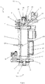
- Figure 1 shows a sectional view of a filling device 1 according to the invention for conveying a fuel.
- the filling device 1 is basically suitable for all pumpable operating materials, i.e. bulk goods, gel-like or pasty substances or liquids, it is used in the exemplary embodiment shown for conveying hot-melt adhesives for packaging machines, for example.
- the hot melt adhesive is provided as bulk material, namely in the form of granules, and stored in a storage or storage tank (not shown) and from there by means of the filling device 1 to a packaging machine or hot-melt adhesive machine (not shown), where the hot-melt adhesive can be melted and applied.
- the filling device 1 has a housing 2 which, in particular, encloses a filling space 3.
- the filling space 3 is essentially cylindrical, but can nevertheless have a different shape and is used to receive said granules.
- An inlet opening 4 is provided on a head side 18 of the filling device 1, via which the granulate can be fed to the filling space 3.
- the filling device 1 furthermore has an exit opening 5 which is used to convey the granulate out of the filling device 1, in particular to said packaging machines or hot-melt glueing machines, not shown.
- the filling space 3 is used in particular for pre-portioning a fixed amount of granules.
- a fill level sensor 20 is provided which monitors the fill level of the granules filled into the filling space 3.
- the level sensor 20 is connected via a control connection, not shown, to a control unit 37, which in turn is able to process the data recorded by the level sensor 20 and, depending on this, control the supply of the granulate via the inlet opening 4 into the filling space 3.
- further or alternative measuring devices can be provided in order to measure the quantity, in particular the volume or the weight, of the in the filling space 3 introduced granules to be monitored.
- the use of a scale (not shown) for the filling device 1 is conceivable in order to determine the additional weight due to the filling with granules.
- the use of a photo sensor or a camera can prove to be useful, which monitor, for example, through a sight glass in the wall of the housing 2 of the filling space 3, how much granulate is in the filling space 3.
- the granules reach the filling chamber 3 by means of a gaseous transport medium through the inlet opening 4.
- Compressed air is used as the gaseous transport medium, the granules being conveyed through the inlet opening 4 into the filling chamber 3 by means of compressed air.
- the granules are filled into the filling opening 4 by means of compressed air.
- An exhaust air opening 15 is provided on the housing 2 in the area of the head side 18 above the filling space 3 and the inlet opening 4 in order to transfer the gaseous transport medium required to convey the granulate into the filling space 3 again through an exhaust air slot 25 and an adjoining and in the exhaust air opening 15 discharging exhaust air duct 26 from the filling space 3.
- a separating screen 14 is provided within the housing 2 in the area of the head side 18 above the filling space 3 and between the inlet opening 4 and the exhaust air opening 15 as a means for separating.
- the separating sieve 14 extends over the entire free cross section within the housing 2 between the inlet opening 4 and the exhaust air opening 15 in such a way that the gaseous transport medium; which is used to convey the granules into the filling space 3, after flowing into the inlet opening 4, flows through the separating sieve 14 in order to reach the exhaust air opening 15.
- the gaseous transport medium which is used to convey the granules into the filling space 3, after flowing into the inlet opening 4
- the filling opening 4 for filling the filling space 3 and the exhaust air opening 15 for discharging the gaseous transport medium are open during the filling process. All other openings of the filling device 1 are, however, closed, which is preferably controlled by said control unit 37.
- the separating sieve 14 has a sieve size that is selected such that the granulate is separated from the gaseous transport medium, so that the granulate enters the filling space 3 located below the separating sieve 4 and the gaseous transport medium can escape through the exhaust air opening 15.
- the separating screen 14 is preferably designed to be exchangeable in order to be able to separate different grain sizes of granules.
- the filling device 1 has a lifting cylinder 12 with an actuator 13 as a means for closing.
- the exhaust air opening 15 or rather the exhaust air slot 25 can furthermore be closed by means of a further lifting cylinder 16 having an adjusting means 17 as a means for closing.
- Both lifting cylinders 12, 16 are activated by the control unit 37.
- other possibilities for closing the openings of the filling device 1, in particular of the inlet opening 4 and the exhaust air opening 15, which are known to the person skilled in the art and are suitable for the respective application, can be provided.
- a line system (not shown) is connected to said exhaust air opening 15, via which the discharged gaseous transport medium from the filling device 1 is returned to said storage tank for the granulate, which is not shown, the line system opening into a storage space of the storage tank in such a way that a ventilation possibility of the Granules located in the storage space can be made possible by the gaseous transport medium discharged through the exhaust air opening 15. In this way, in particular, cooling for the granules located there and / or loosening of the granules can be made possible.
- the filling space 3 opens with a funnel 24 in an opening designed as a transition 7, which in the shown state of the filling device 7 is closed by the actuator of a lifting cylinder 8.
- the actuator of the lifting cylinder 8 extends over a conveying section 6, which serves to convey the granulate out of the filling device 1 via the outlet opening 5.
- the filling device 1 also has a further connection for a gaseous transport medium, here a compressed air connection 10 with a compressed air nozzle 11 directed onto or into the conveying section 6, for applying compressed air to the conveying section 6 to convey the granules from the outlet 5
- a gaseous transport medium here a compressed air connection 10 with a compressed air nozzle 11 directed onto or into the conveying section 6, for applying compressed air to the conveying section 6 to convey the granules from the outlet 5
- the filling space 3 is separated from the conveying section 6 by means of the actuator of the lifting cylinder 8, which blocks or closes the transition 7, so that no granules can get from the filling space 3 into the conveying section 6.
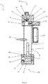
- FIG. 11 shows a sectional view of the filling device 1 from FIG Figure 1 in the output state.
- the above-described supply of the granulate through the inlet opening 4 ion the filling space 3 is here completed.
- the supply of the granules by means of the gaseous transport medium continued until the level sensor 20 measured a fixed volume of granules in the filling space 3.
- the control unit 37 then switched off the supply of the granulate either actively to the storage tank or storage tank (not shown).
- the lifting cylinder 12 located in the housing 2 has been activated by the control unit 37 as a means for closing the inlet opening 4 having a movable actuator 13, which is arranged and designed in such a way that the inlet opening 4 is closed by means of a movement of the actuator 13 opposite to Direction of flow of the gaseous transport medium when filling the filling space 3 is made possible.
- the further lifting cylinder 16 is provided with an actuator 17 in the area of the head side 18 above the separating sieve 14, which serves to close the exhaust air opening 15, the actuator 17 being designed in such a way that it uses the exhaust air opening 15 or rather the exhaust air slot 25 as a flow path to the exhaust air opening 15 has closed by a movement of the actuator 16 opposite to the flow direction of the gaseous transport medium.
- the activation of the lifting cylinder 16 also took place here by means of the control unit 37 after the defined filling volume in the filling space 3 had been recorded by the filling level sensor 20.
- the lifting cylinder 8 has been activated by the control unit 37 and the in Figure 1 closed state shown, in which the actuator of the lifting cylinder 8 blocks the transition 7 and therefore the junction 7 was in the closed position, has been transferred to an open state in which the junction 7 is released and is therefore in the open position.
- the actuator was moved in a direction which runs from the head side 18 in the direction of the bottom side 19.
- the movement of the actuator took place in such a way that the conveying section 6 arranged below the transition 7 and the filling space 3 was released, as well as the compressed air nozzle 11 opening into the conveying section 6 and the outlet opening 5 opposite the compressed air nozzle 11 communicating with the conveying section 6 via an outlet channel
- the compressed air nozzle 11 serves to act on the conveying section 6 with a gaseous transport medium, in the present case compressed air, to output the granulate from the outlet opening 5.
- the granules filled through the inlet opening 4 into the filling space 3 can reach the conveying section 6. On the one hand, this can take place by means of gravitational force, since the conveying section 6 is provided below the filling space 3, as described above. According to the invention, however, a gaseous transport medium is used here.
- the filling device 1 has a compressed air connection 9 above the separating sieve 14, through which compressed air can be introduced into the filling space 3 as said gaseous transport medium for transferring the granulate from the filling space 3 into the conveying section 6.
- the compressed air introduced into the filling device 1 by means of the compressed air connection flows through the separating sieve 14 to reach the filling space 3, in this case in the opposite direction to the exhaust air described above, which flows through the separating sieve 14 and then through the in Figure 2 closed exhaust air opening 15 is led out of the filling device 1.
- a cleaning of the separating sieve 14 can be made possible by this flow through, since any granules stuck in the meshes are blown out and get into the filling space 3.
- the compressed air flows further into the filling chamber 3 and transfers the granulate from there through the transition 7 in the open position into the conveying section 6.
- the conveying section 6 is pressurized by means of the compressed air nozzle 11 to convey the material that has passed from the filling chamber 3 into the conveying section 6 Granules.
- the connection of the nozzle 11 is connected to the compressed air connection 9 described above via a pipe connection 22, so that compressed air is simultaneously supplied to the filling device 1 both via the nozzle 11 and via the compressed air connection 9. The same is again controlled by the control unit 37 here.
- a first gaseous transport medium is fed to the filling device via the compressed air connection 9 into the filling space 3 for transporting the granules into the conveying section 6 and a second gaseous transport medium is fed via the nozzle 11 into the conveying section 6 for conveying the granulate from the outlet opening 5.
- the actuator of the lifting cylinder 8 has been displaced in such a way that communication between the conveying section 6 and the outlet opening is possible via said outlet channel.
- the compressed air introduced into the conveying section 6 via the compressed air connection 9 and the nozzle 11 can thus escape via the outlet opening 5, with the granulate being conveyed from the outlet opening 5 can be guaranteed. Accordingly, the granules are conveyed out of the outlet opening 5 not only using the compressed air introduced via the compressed air nozzle 11, but also using the compressed air supplied to the filling chamber 3 via the compressed air connection 9, which is used to transfer the granules from the filling chamber 3 to the Funding section 6 was used.
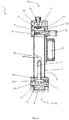
- Figure 3 shows a sectional view of an alternative filling device 1 according to the invention in the filling state.
- This filling device also has the top side 18 and the bottom side 19 as well as the housing 2, which encloses the filling space 3 for receiving a granulate.
- the function and the basic mode of operation corresponds to that of the Figures 1 and 2 Filling device 1 shown, so that the corresponding passages in the description can also be read on this filling device 1.
- the conveying section 6 of the filling device 1 shown here. This extends as an essentially hollow cylindrical tube within the filling space 3, the tube opening in the direction of the head side 18 in an arc segment and out of the filling space 3 in a side wall of the housing 2 in the Exit opening 5 opens.
- the tube is also designed to be open in the direction of the bottom side 19.
- the free area of the filling space between the conveying section 6 and the inner wall of the housing 2 is designed here as a transition 7, via which the granulate can be transferred from the filling space 3 into the conveying section 6.
- the transition 7 is in the closed state.
- the transition 7 is closed here by the actuator of a lifting cylinder provided on the bottom side 19, so that no communication between the filling space 3 and the conveying section 6 is possible.
- the actuator of the lifting cylinder 8 has a cross section that corresponds approximately to the filling space 3 and forms the bottom area of the filling space 3.
- the upper side of the actuator has a funnel-shaped area 24.
- the actuator has a channel 27 with which communication between the compressed air nozzle 11 and the conveying section 6 for dispensing the granulate from the dispensing opening 5 can be made possible.
- FIG. 4 shows a sectional view of the device from FIG Figure 3 in the output state.
- the control unit 37 is actuated by the lifting cylinder 8, so that its actuator moves in the direction of the bottom side 19, that is, opposite to the flow direction of the granulate, and releases the transition 7.
- the transition 7 is thus in the open position, so that communication from filling space 3 and conveyor section 6 is possible.
- the funnel-shaped region 27 of the actuator forms a funnel 24 on the bottom of the filling space 3.
- the channel 27 is coupled to the compressed air nozzle 11.
- the channel 27 extends through the actuator at an angle in such a way that it opens out on its upper side and opposite the inlet of the conveying section 6.
- FIGS Figure 5 a schematic view of a dispensing system 100 according to the invention comprising one in FIGS Figures 1 to 4 Filling device 1 shown for conveying a granulate and a storage container 29 for receiving the granulate with a bottom discharge funnel 31, the storage container 19 being connected to the filling device 1 via a feed line 32.
- the filling space 3 of the filling device 1 is filled with the granules from the storage container 29 by means of a gaseous transport medium, the filling device having an exhaust air opening 15 described above in order to discharge the gaseous transport medium and a means for separating 14 the granules being provided which is designed in such a way that a separation of the granules from the gaseous transport medium is possible, so that the granules reach the filling space 3 and the gaseous transport medium escapes through the exhaust air opening 15.
- an exhaust air line 33 is connected to the exhaust air opening 15 and opens into the storage container 29, the exhaust air being used for temperature control, in particular for cooling the granulate located in the storage container 29.
- application units 36 are provided for melting and applying the granulate, which are connected to the outlet opening 5 of the filling device 1 by means of discharge lines 34 via a switch 35 via, in turn, a discharge line 34. Accordingly, a large number of discharge units 34 can be supplied by means of a filling device 1, the granules being distributed by means of the switch 35, which can be controlled, for example, via the control unit 37 of the application unit 1.
Landscapes
- Engineering & Computer Science (AREA)
- Mechanical Engineering (AREA)
- Physics & Mathematics (AREA)
- Fluid Mechanics (AREA)
- General Physics & Mathematics (AREA)
- Filling Or Emptying Of Bunkers, Hoppers, And Tanks (AREA)
- Basic Packing Technique (AREA)
- Air Transport Of Granular Materials (AREA)
Claims (10)
- Dispositif (1) permettant l'acheminement d'une matière de service, présentant une chambre de remplissage (3) comportant une entrée (4) permettant le remplissage de la chambre de remplissage (3) avec la matière de service, un segment d'acheminement (6) permettant l'acheminement de la matière de service par l'intermédiaire d'une sortie (5), un élément de transition (7) depuis la chambre de remplissage (3) jusqu'au segment d'acheminement (6), un moyen de fermeture (8) de l'élément de transition (7) étant prévu entre la chambre de remplissage (3) et le segment d'acheminement (6), le moyen de fermeture (8) présentant un actionneur (8) et étant conçu de manière à pouvoir fermer l'élément de transition (7) en déplaçant l'actionneur (8) dans le sens opposé au sens de transfert de la matière de service depuis la chambre de remplissage (3) jusqu'au segment d'acheminement (6), pour basculer entre une position ouverte et une position fermée de l'élément de transition (7) afin de permettre, dans la position ouverte, une communication entre la chambre de remplissage (3) et le segment d'acheminement (6) et, dans la position fermée, une isolation du segment d'acheminement (6) de la chambre de remplissage (3), la chambre de remplissage (3) présentant une alimentation (9) permettant d'alimenter de l'air comprimé en tant que milieu de transport gazeux afin de transférer, dans la position ouverte de l'élément de transition (7), la matière de service alimentée dans la chambre de remplissage (3) à travers l'entrée (4) vers le segment d'acheminement (6) et afin de distribuer la matière de service à partir du segment d'acheminement (6) hors de la sortie (5), la chambre de remplissage (3) étant remplie avec la matière de service au moyen d'un milieu de transport gazeux, une ouverture d'évacuation d'air (15) étant prévue afin de décharger le milieu de transport gazeux, et un moyen de séparation (14) de la matière de service étant prévu, lequel est conçu de manière à permettre que la matière de service soit séparée du milieu de transport gazeux, de sorte que la matière de service atteint la chambre de remplissage (3) et que le milieu de transport gazeux s'échappe à travers l'ouverture d'évacuation d'air (15).
- Dispositif (1) selon la revendication 1, caractérisé en ce que de l'air comprimé est alimenté en tant que premier milieu de transport gazeux dans la chambre de remplissage (3) pour transporter la matière de service dans le segment d'acheminement (6) et que de l'air comprimé est alimenté en tant que second milieu de transport gazeux dans le segment d'acheminement (3) pour transporter la matière de service hors de la sortie (5), en particulier jusqu'à une station de traitement raccordée à la sortie (5).
- Dispositif (1) selon la revendication 2, caractérisé en ce que les premier et second milieux de transport gazeux sont amenés simultanément, au moins temporairement, dans la chambre de remplissage (3) ou dans le segment d'acheminement (6) dans la position ouverte de l'élément de transition (7), afin de permettre une distribution de la matière de service hors de la sortie (5) par à la fois le premier et le second milieu de transport gazeux.
- Dispositif selon la revendication 1, caractérisé en ce que le moyen de séparation (14) est réalisé sous la forme d'une grille ou d'un tamis disposé dans la chambre de remplissage (3).
- Dispositif (1) selon l'une des revendications précédentes, caractérisé en ce que le moyen de séparation (14) est disposé entre un segment d'alimentation (9) destiné à l'air comprimé en tant que milieu de transport gazeux et le segment d'acheminement (6), de telle sorte que le milieu de transport gazeux, au moyen duquel la matière de service est transférée, dans la position ouverte de l'élément de transition (7), depuis la chambre de remplissage (3) jusqu'au segment d'acheminement (6), s'écoule pendant l'alimentation et pendant le transfert de la matière de service à travers le moyen de séparation (14) afin de permettre le nettoyage du moyen de séparation (14) par ledit milieu de transport gazeux.
- Dispositif (1) selon l'une des revendications précédentes, caractérisé en ce qu'un moyen de fermeture (16, 17, 12, 13) de l'ouverture d'évacuation d'air (15) et/ou de l'entrée (4) est prévu, le moyen de fermeture (16, 17,12,13) présentant un actionneur (13, 17) et étant conçu de telle sorte qu'il peut fermer l'ouverture d'évacuation d'air (15) et/ou l'entrée (4) en déplaçant l'actionneur (13, 17) dans le sens d'écoulement du milieu de transport gazeux ou dans le sens opposé à celui-ci.
- Dispositif (1) selon l'une des revendications précédentes, caractérisé en ce que la zone inférieure de la chambre de remplissage (3) tournée vers l'élément de transition (7) est en forme d'entonnoir (24, 27) et débouche de préférence dans l'élément de transition (7).
- Système de distribution (100) comprenant un dispositif (1) d'acheminement d'une matière de service selon l'une des revendications 1 à 7, un réservoir de stockage (29) permettant de recevoir la matière de service, le réservoir de stockage (19) étant relié au dispositif (1) par l'intermédiaire d'une conduite d'alimentation (32).
- Système de distribution (100) selon la revendication 8, caractérisé en ce que le réservoir de stockage (29) présentant une chambre de stockage destinée à la matière de service est prévu pour remplir la chambre de remplissage (3) au moyen d'air comprimé en tant que milieu de transport gazeux, ladite ouverture d'évacuation d'air (15) étant raccordée à un système de conduite qui débouche dans la chambre de stockage afin de permettre une ventilation de la matière de service située dans la chambre de stockage par le milieu de transport gazeux déchargé à travers l'ouverture d'évacuation d'air (15).
- Système de distribution (100) selon l'une des revendications 8 ou 9, caractérisé en ce que la chambre de remplissage (3) du dispositif (1) est remplie avec la matière de service à partir du réservoir de stockage (29) au moyen d'air comprimé en tant que milieu de transport gazeux, le dispositif (1) présentant une ouverture d'évacuation d'air (15) pour décharger le milieu de transport gazeux, et un moyen de séparation (14) de la matière de service étant prévu, lequel est conçu de manière à permettre que la matière de service soit séparée du milieu de transport gazeux, de sorte que la matière de service atteint la chambre de remplissage (3) et que le milieu de transport gazeux s'échappe à travers l'ouverture d'évacuation d'air (15), une conduite d'évacuation d'air (33) qui débouche dans le réservoir de stockage (29) étant raccordée à l'ouverture d'évacuation d'air (15).
Applications Claiming Priority (2)
| Application Number | Priority Date | Filing Date | Title |
|---|---|---|---|
| DE102012224054.3A DE102012224054A1 (de) | 2012-12-20 | 2012-12-20 | Vorrichtung zum Befördern eines Betriebsstoffes |
| PCT/EP2013/075387 WO2014095349A1 (fr) | 2012-12-20 | 2013-12-03 | Dispositif d'acheminement de matière |
Publications (2)
| Publication Number | Publication Date |
|---|---|
| EP2936084A1 EP2936084A1 (fr) | 2015-10-28 |
| EP2936084B1 true EP2936084B1 (fr) | 2021-03-24 |
Family
ID=49683750
Family Applications (1)
| Application Number | Title | Priority Date | Filing Date |
|---|---|---|---|
| EP13799066.9A Active EP2936084B1 (fr) | 2012-12-20 | 2013-12-03 | Dispositif d'acheminement de matière |
Country Status (7)
| Country | Link |
|---|---|
| US (1) | US9688486B2 (fr) |
| EP (1) | EP2936084B1 (fr) |
| JP (1) | JP6230615B2 (fr) |
| CN (2) | CN113650819A (fr) |
| DE (1) | DE102012224054A1 (fr) |
| TW (1) | TWI603908B (fr) |
| WO (1) | WO2014095349A1 (fr) |
Families Citing this family (2)
| Publication number | Priority date | Publication date | Assignee | Title |
|---|---|---|---|---|
| DE102012224054A1 (de) * | 2012-12-20 | 2014-06-26 | Henkel Ag & Co. Kgaa | Vorrichtung zum Befördern eines Betriebsstoffes |
| US10226917B2 (en) * | 2015-07-27 | 2019-03-12 | Dmg Mori Seiki Usa | Powder delivery systems and methods for additive manufacturing apparatus |
Citations (3)
| Publication number | Priority date | Publication date | Assignee | Title |
|---|---|---|---|---|
| DE2409128A1 (de) * | 1974-02-26 | 1975-09-11 | Karl Hehl | Vorrichtung zur automatischen beschikkung einer verarbeitungsmaschine mit rieselfaehigem gut |
| DE102010060114A1 (de) * | 2010-10-22 | 2012-04-26 | Thönnißen Möller Engineering GmbH | Verfahren und Vorrichtung zur pneumatischen Förderung und/oder Dosierung eines Schüttguts |
| DE102011001276A1 (de) * | 2011-03-15 | 2012-09-20 | Symelt Gmbh | Entlüftungsvorrichtung |
Family Cites Families (37)
| Publication number | Priority date | Publication date | Assignee | Title |
|---|---|---|---|---|
| US2734782A (en) * | 1956-02-14 | Pneumatic conveyors | ||
| US2707132A (en) * | 1951-11-23 | 1955-04-26 | Baresch Charles Albert | Pneumatic conveyor apparatus |
| FR1098596A (fr) * | 1954-01-19 | 1955-08-08 | Procédé pour assurer le débit d'une poudre fine par un orifice et dispositif pour le mettre en oeuvre | |
| US3094249A (en) * | 1959-04-14 | 1963-06-18 | British Oxygen Co Ltd | Powder dispensing apparatus |
| US3432208A (en) * | 1967-11-07 | 1969-03-11 | Us Air Force | Fluidized particle dispenser |
| JPS527238B2 (fr) * | 1972-07-15 | 1977-03-01 | ||
| US3827610A (en) * | 1972-08-09 | 1974-08-06 | H Stiefel | Volumetric filling device |
| DE2443865A1 (de) * | 1974-09-13 | 1976-03-25 | Freier Grunder Eisen Metall | Vorrichtung zum einschleusen und schubweisen foerdern von rieselfaehigen guetern, insbesondere granulate und giessereisand |
| JPS53113594U (fr) * | 1977-02-17 | 1978-09-09 | ||
| JPS578417A (en) * | 1980-06-19 | 1982-01-16 | Mitsubishi Keikinzoku Kogyo Kk | Metering device for powder and granule |
| US4497599A (en) * | 1981-03-23 | 1985-02-05 | Advance Engineering, Inc. | System for preventing clogging of the outlet orifice of a dispenser tank containing powdered reagent and auxiliary tank discharge means |
| US4502819A (en) * | 1981-06-12 | 1985-03-05 | Denka Engineering Kabushiki Kaisha | Constant discharge device in a conveyor for powdery and granular materials |
| DE3230315C2 (de) * | 1982-08-14 | 1986-11-27 | Bühler-Miag GmbH, 3300 Braunschweig | Vorrichtung zum Einbringen von Schüttgut in eine pneumatische Druckförderleitung |
| JPS59190112A (ja) * | 1983-04-09 | 1984-10-27 | Matsui Seisakusho:Kk | 粉粒体の投入供給方法とその装置 |
| US4472091A (en) * | 1983-04-25 | 1984-09-18 | Pennwalt Corporation | Dry powder metering apparatus |
| DE3420616A1 (de) * | 1984-06-02 | 1985-12-05 | Alb. Klein Gmbh & Co Kg, 5241 Niederfischbach | Vorrichtung und verfahren zur steuerung eines schleusvorganges fuer ein haufwerk von schuettgutpartikeln |
| JPS612328U (ja) * | 1984-06-11 | 1986-01-09 | 株式会社 朋来鐵工所 | ホツパロ−ダにおけるダンパ構造 |
| SU1207937A1 (ru) * | 1984-10-30 | 1986-01-30 | Пкб@"Главстроймеханизация" | Склад дл хранени сыпучих материалов |
| JPH0225136Y2 (fr) * | 1985-01-25 | 1990-07-11 | ||
| GB8511122D0 (en) * | 1985-05-01 | 1985-06-12 | Wildon K | Discharging particulate material |
| DE3621149A1 (de) * | 1986-06-24 | 1988-01-14 | Werner Knippenberg | Anlage zum einschleusen von schuett- oder rieselfaehigem feststoff-foerdergut in den luftstrom einer luftfoerderleitung, sowie verfahren zum betreiben der anlage |
| US5340241A (en) * | 1992-02-04 | 1994-08-23 | Motan, Inc. | Device for metering and entraining a product into a gas stream |
| FI97217C (fi) * | 1995-03-07 | 1996-11-11 | Wiser Oy | Annostelijalaite |
| SE9603063D0 (sv) * | 1996-08-23 | 1996-08-23 | Astra Ab | Device and method for metering a particulate substance and apparatus comprising a plurality of such devices |
| US6079461A (en) * | 1998-08-17 | 2000-06-27 | The Heil Co. | Use of inert gas in transfer of comminuted product to tank |
| DE10153425A1 (de) * | 2001-11-03 | 2003-05-15 | Pfister Gmbh | Verfahren und Vorrichtung zum gravimetrischen Dosieren von Schüttgut |
| US6722294B2 (en) * | 2002-08-06 | 2004-04-20 | Vitro Global, S.A. | Method and apparatus for feeding a pulverized material |
| US7846399B2 (en) * | 2004-03-23 | 2010-12-07 | W.R. Grace & Co.-Conn. | System and process for injecting catalyst and/or additives into a fluidized catalytic cracking unit |
| US7231947B2 (en) * | 2004-06-08 | 2007-06-19 | The Young Industries, Inc. | System for pneumatically conveying bulk materials with improved discharge arrangement |
| JP2006112527A (ja) * | 2004-10-14 | 2006-04-27 | Kawata Mfg Co Ltd | 気力輸送用開閉弁、配管切換装置および粉粒体計量装置 |
| US20100284768A1 (en) * | 2007-10-04 | 2010-11-11 | Olin-Nunez Miguel Angel | Method and apparatus for feeding a pulverized material |
| JP5160292B2 (ja) * | 2008-04-21 | 2013-03-13 | バブコック日立株式会社 | 加圧粉体供給装置及びその運転方法 |
| DE102009007116B4 (de) * | 2009-02-02 | 2015-02-19 | Henkel Ag & Co. Kgaa | Behälter mit Ventil für eine Abgabepistole und Abgabesystem |
| DE202009005561U1 (de) | 2009-04-16 | 2009-07-02 | Fass, Wolfgang, Dipl.-Ing. | Vorrichtung und Anordnung zum Befüllen von Verarbeitungsstationen |
| CN201971173U (zh) * | 2011-01-25 | 2011-09-14 | 侯秋香 | 气力物料输送系统 |
| DE102012224054A1 (de) * | 2012-12-20 | 2014-06-26 | Henkel Ag & Co. Kgaa | Vorrichtung zum Befördern eines Betriebsstoffes |
| US8936416B2 (en) * | 2013-05-01 | 2015-01-20 | Crystal-Mark, Inc., A Swan Technologies Corporation | Fluidized particle abrasion device with precision control |
-
2012
- 2012-12-20 DE DE102012224054.3A patent/DE102012224054A1/de not_active Withdrawn
-
2013
- 2013-12-03 CN CN202111002411.0A patent/CN113650819A/zh active Pending
- 2013-12-03 CN CN201380066051.8A patent/CN104854432A/zh active Pending
- 2013-12-03 US US14/654,048 patent/US9688486B2/en not_active Expired - Fee Related
- 2013-12-03 WO PCT/EP2013/075387 patent/WO2014095349A1/fr not_active Ceased
- 2013-12-03 EP EP13799066.9A patent/EP2936084B1/fr active Active
- 2013-12-03 JP JP2015548329A patent/JP6230615B2/ja not_active Expired - Fee Related
- 2013-12-06 TW TW102144760A patent/TWI603908B/zh not_active IP Right Cessation
Patent Citations (3)
| Publication number | Priority date | Publication date | Assignee | Title |
|---|---|---|---|---|
| DE2409128A1 (de) * | 1974-02-26 | 1975-09-11 | Karl Hehl | Vorrichtung zur automatischen beschikkung einer verarbeitungsmaschine mit rieselfaehigem gut |
| DE102010060114A1 (de) * | 2010-10-22 | 2012-04-26 | Thönnißen Möller Engineering GmbH | Verfahren und Vorrichtung zur pneumatischen Förderung und/oder Dosierung eines Schüttguts |
| DE102011001276A1 (de) * | 2011-03-15 | 2012-09-20 | Symelt Gmbh | Entlüftungsvorrichtung |
Also Published As
| Publication number | Publication date |
|---|---|
| JP6230615B2 (ja) | 2017-11-15 |
| JP2016500359A (ja) | 2016-01-12 |
| TWI603908B (zh) | 2017-11-01 |
| WO2014095349A1 (fr) | 2014-06-26 |
| CN113650819A (zh) | 2021-11-16 |
| CN104854432A (zh) | 2015-08-19 |
| DE102012224054A1 (de) | 2014-06-26 |
| EP2936084A1 (fr) | 2015-10-28 |
| US20160083200A1 (en) | 2016-03-24 |
| US9688486B2 (en) | 2017-06-27 |
| TW201429850A (zh) | 2014-08-01 |
Similar Documents
| Publication | Publication Date | Title |
|---|---|---|
| EP0423559B2 (fr) | Installation de transport pneumatique à aspiration pour alimenter gravimétriquement des composants de matières en vrac | |
| DE102011112016B3 (de) | Verfahren zum Reinigen von Dosiervorrichtungen, die zum Beschicken von Vorrichtungen - zum Beispiel Extruder, Spritzgussmaschinen oder dergleichen - mit Schüttgütern - Pellets, Spänen, Granulaten, Pulvern, Flakes, Körnen, Mehl oder dergleichen - dienen, und Vorrichtung zur Durchführung eines derartigen Verfahrens und Steuerung für die Reinigung einer derartigen Dosiervorrichtung | |
| EP2799374B1 (fr) | Système et procédé de sortie de récipients de boisson d'un dispositif de transport se déplaçant | |
| EP3010812B1 (fr) | Machine d'emballage et procédé | |
| DE69804959T2 (de) | Verfahren und vorrichtung zum transport von schüttgut, körnigem material oder pulverförmigem material | |
| EP3238832B2 (fr) | Dispositif de transport destine a transporter de la poudre de revetement vers un applicateur de poudre, installation de revetement de poudre et procede de fonctionnement d'un dispositif de revetement de poudre | |
| EP2196079B1 (fr) | Système de remplissage | |
| EP1469289B1 (fr) | Dispositif de dosage pour pigments pulvérulants | |
| EP1319615A2 (fr) | Installation pour le chargement des utilisateurs avec matière en vrac pulverulent | |
| EP2349845A1 (fr) | Dispositif d'ensachage de produit en vrac | |
| EP2359704B1 (fr) | Dispositif et procédé de réunion de flux de matière, notamment pour une cartouche de vidage | |
| DE102015114147A1 (de) | Dosiervorrichtung für granulares Material mit Körnerzähler | |
| DE4335074C1 (de) | Vorrichtung zum Beschicken einer einer Verpackungseinrichtung vorgeschalteten Wägeeinrichtung mit zerbrechlichen Lebensmitteln unregelmäßiger Größe und ähnlichen Produkten, insbesondere Kartoffelchips | |
| EP2936084B1 (fr) | Dispositif d'acheminement de matière | |
| DE3900664A1 (de) | Verfahren und vorrichtung zum reinigen des rohmaterial-beschickungsbehaelters einer verarbeitungsmaschine | |
| DE102008020218B3 (de) | Verfahren und Vorrichtung zur Überführung von fließfähigem Schüttgut | |
| EP4180777B1 (fr) | Dispositif de pesage et de transport et procédé de transport et de détection du débit massique de produits en vrac | |
| EP0468399A2 (fr) | Dispositif pour le dosage et/ou le mélange continu, pneumatique gravimetrique de marchandises en vrac | |
| EP2241867A1 (fr) | Dispositif et agencement destinés au remplissage de postes de traitement | |
| EP2152586B1 (fr) | Emballeuse | |
| WO2023135219A1 (fr) | Dispositif de séparation et de mesure d'un produit en vrac de petit volume | |
| DE102008050729A1 (de) | Packmaschine und Verfahren zum Füllen von Schüttgütern in Säcke | |
| EP1803664B1 (fr) | Dispositif pour l'interruption d'un flux continu de produits dans une presse rotative | |
| WO2005012147A2 (fr) | Procede et dispositif pour transporter des composants dans une voie de transport tubulaire | |
| DE10226722B4 (de) | Waage zur Erfassung des Massendurchsatzes nach dem Differentialprinzip |
Legal Events
| Date | Code | Title | Description |
|---|---|---|---|
| PUAI | Public reference made under article 153(3) epc to a published international application that has entered the european phase |
Free format text: ORIGINAL CODE: 0009012 |
|
| 17P | Request for examination filed |
Effective date: 20150608 |
|
| AK | Designated contracting states |
Kind code of ref document: A1 Designated state(s): AL AT BE BG CH CY CZ DE DK EE ES FI FR GB GR HR HU IE IS IT LI LT LU LV MC MK MT NL NO PL PT RO RS SE SI SK SM TR |
|
| AX | Request for extension of the european patent |
Extension state: BA ME |
|
| DAX | Request for extension of the european patent (deleted) | ||
| TPAC | Observations filed by third parties |
Free format text: ORIGINAL CODE: EPIDOSNTIPA |
|
| STAA | Information on the status of an ep patent application or granted ep patent |
Free format text: STATUS: EXAMINATION IS IN PROGRESS |
|
| 17Q | First examination report despatched |
Effective date: 20180607 |
|
| GRAP | Despatch of communication of intention to grant a patent |
Free format text: ORIGINAL CODE: EPIDOSNIGR1 |
|
| STAA | Information on the status of an ep patent application or granted ep patent |
Free format text: STATUS: GRANT OF PATENT IS INTENDED |
|
| INTG | Intention to grant announced |
Effective date: 20201217 |
|
| GRAS | Grant fee paid |
Free format text: ORIGINAL CODE: EPIDOSNIGR3 |
|
| GRAA | (expected) grant |
Free format text: ORIGINAL CODE: 0009210 |
|
| STAA | Information on the status of an ep patent application or granted ep patent |
Free format text: STATUS: THE PATENT HAS BEEN GRANTED |
|
| AK | Designated contracting states |
Kind code of ref document: B1 Designated state(s): AL AT BE BG CH CY CZ DE DK EE ES FI FR GB GR HR HU IE IS IT LI LT LU LV MC MK MT NL NO PL PT RO RS SE SI SK SM TR |
|
| REG | Reference to a national code |
Ref country code: GB Ref legal event code: FG4D Free format text: NOT ENGLISH |
|
| REG | Reference to a national code |
Ref country code: CH Ref legal event code: EP |
|
| REG | Reference to a national code |
Ref country code: IE Ref legal event code: FG4D Free format text: LANGUAGE OF EP DOCUMENT: GERMAN |
|
| REG | Reference to a national code |
Ref country code: AT Ref legal event code: REF Ref document number: 1374953 Country of ref document: AT Kind code of ref document: T Effective date: 20210415 Ref country code: DE Ref legal event code: R096 Ref document number: 502013015591 Country of ref document: DE |
|
| REG | Reference to a national code |
Ref country code: LT Ref legal event code: MG9D |
|
| PG25 | Lapsed in a contracting state [announced via postgrant information from national office to epo] |
Ref country code: GR Free format text: LAPSE BECAUSE OF FAILURE TO SUBMIT A TRANSLATION OF THE DESCRIPTION OR TO PAY THE FEE WITHIN THE PRESCRIBED TIME-LIMIT Effective date: 20210625 Ref country code: HR Free format text: LAPSE BECAUSE OF FAILURE TO SUBMIT A TRANSLATION OF THE DESCRIPTION OR TO PAY THE FEE WITHIN THE PRESCRIBED TIME-LIMIT Effective date: 20210324 Ref country code: FI Free format text: LAPSE BECAUSE OF FAILURE TO SUBMIT A TRANSLATION OF THE DESCRIPTION OR TO PAY THE FEE WITHIN THE PRESCRIBED TIME-LIMIT Effective date: 20210324 Ref country code: BG Free format text: LAPSE BECAUSE OF FAILURE TO SUBMIT A TRANSLATION OF THE DESCRIPTION OR TO PAY THE FEE WITHIN THE PRESCRIBED TIME-LIMIT Effective date: 20210624 Ref country code: NO Free format text: LAPSE BECAUSE OF FAILURE TO SUBMIT A TRANSLATION OF THE DESCRIPTION OR TO PAY THE FEE WITHIN THE PRESCRIBED TIME-LIMIT Effective date: 20210624 |
|
| PG25 | Lapsed in a contracting state [announced via postgrant information from national office to epo] |
Ref country code: SE Free format text: LAPSE BECAUSE OF FAILURE TO SUBMIT A TRANSLATION OF THE DESCRIPTION OR TO PAY THE FEE WITHIN THE PRESCRIBED TIME-LIMIT Effective date: 20210324 Ref country code: RS Free format text: LAPSE BECAUSE OF FAILURE TO SUBMIT A TRANSLATION OF THE DESCRIPTION OR TO PAY THE FEE WITHIN THE PRESCRIBED TIME-LIMIT Effective date: 20210324 Ref country code: LV Free format text: LAPSE BECAUSE OF FAILURE TO SUBMIT A TRANSLATION OF THE DESCRIPTION OR TO PAY THE FEE WITHIN THE PRESCRIBED TIME-LIMIT Effective date: 20210324 |
|
| REG | Reference to a national code |
Ref country code: NL Ref legal event code: MP Effective date: 20210324 |
|
| PG25 | Lapsed in a contracting state [announced via postgrant information from national office to epo] |
Ref country code: NL Free format text: LAPSE BECAUSE OF FAILURE TO SUBMIT A TRANSLATION OF THE DESCRIPTION OR TO PAY THE FEE WITHIN THE PRESCRIBED TIME-LIMIT Effective date: 20210324 |
|
| PG25 | Lapsed in a contracting state [announced via postgrant information from national office to epo] |
Ref country code: LT Free format text: LAPSE BECAUSE OF FAILURE TO SUBMIT A TRANSLATION OF THE DESCRIPTION OR TO PAY THE FEE WITHIN THE PRESCRIBED TIME-LIMIT Effective date: 20210324 Ref country code: EE Free format text: LAPSE BECAUSE OF FAILURE TO SUBMIT A TRANSLATION OF THE DESCRIPTION OR TO PAY THE FEE WITHIN THE PRESCRIBED TIME-LIMIT Effective date: 20210324 Ref country code: CZ Free format text: LAPSE BECAUSE OF FAILURE TO SUBMIT A TRANSLATION OF THE DESCRIPTION OR TO PAY THE FEE WITHIN THE PRESCRIBED TIME-LIMIT Effective date: 20210324 Ref country code: SM Free format text: LAPSE BECAUSE OF FAILURE TO SUBMIT A TRANSLATION OF THE DESCRIPTION OR TO PAY THE FEE WITHIN THE PRESCRIBED TIME-LIMIT Effective date: 20210324 |
|
| PG25 | Lapsed in a contracting state [announced via postgrant information from national office to epo] |
Ref country code: IS Free format text: LAPSE BECAUSE OF FAILURE TO SUBMIT A TRANSLATION OF THE DESCRIPTION OR TO PAY THE FEE WITHIN THE PRESCRIBED TIME-LIMIT Effective date: 20210724 Ref country code: RO Free format text: LAPSE BECAUSE OF FAILURE TO SUBMIT A TRANSLATION OF THE DESCRIPTION OR TO PAY THE FEE WITHIN THE PRESCRIBED TIME-LIMIT Effective date: 20210324 Ref country code: SK Free format text: LAPSE BECAUSE OF FAILURE TO SUBMIT A TRANSLATION OF THE DESCRIPTION OR TO PAY THE FEE WITHIN THE PRESCRIBED TIME-LIMIT Effective date: 20210324 Ref country code: PT Free format text: LAPSE BECAUSE OF FAILURE TO SUBMIT A TRANSLATION OF THE DESCRIPTION OR TO PAY THE FEE WITHIN THE PRESCRIBED TIME-LIMIT Effective date: 20210726 Ref country code: PL Free format text: LAPSE BECAUSE OF FAILURE TO SUBMIT A TRANSLATION OF THE DESCRIPTION OR TO PAY THE FEE WITHIN THE PRESCRIBED TIME-LIMIT Effective date: 20210324 Ref country code: ES Free format text: LAPSE BECAUSE OF FAILURE TO SUBMIT A TRANSLATION OF THE DESCRIPTION OR TO PAY THE FEE WITHIN THE PRESCRIBED TIME-LIMIT Effective date: 20210324 |
|
| REG | Reference to a national code |
Ref country code: DE Ref legal event code: R097 Ref document number: 502013015591 Country of ref document: DE |
|
| PG25 | Lapsed in a contracting state [announced via postgrant information from national office to epo] |
Ref country code: DK Free format text: LAPSE BECAUSE OF FAILURE TO SUBMIT A TRANSLATION OF THE DESCRIPTION OR TO PAY THE FEE WITHIN THE PRESCRIBED TIME-LIMIT Effective date: 20210324 Ref country code: AL Free format text: LAPSE BECAUSE OF FAILURE TO SUBMIT A TRANSLATION OF THE DESCRIPTION OR TO PAY THE FEE WITHIN THE PRESCRIBED TIME-LIMIT Effective date: 20210324 |
|
| PLBE | No opposition filed within time limit |
Free format text: ORIGINAL CODE: 0009261 |
|
| STAA | Information on the status of an ep patent application or granted ep patent |
Free format text: STATUS: NO OPPOSITION FILED WITHIN TIME LIMIT |
|
| PG25 | Lapsed in a contracting state [announced via postgrant information from national office to epo] |
Ref country code: SI Free format text: LAPSE BECAUSE OF FAILURE TO SUBMIT A TRANSLATION OF THE DESCRIPTION OR TO PAY THE FEE WITHIN THE PRESCRIBED TIME-LIMIT Effective date: 20210324 |
|
| 26N | No opposition filed |
Effective date: 20220104 |
|
| PG25 | Lapsed in a contracting state [announced via postgrant information from national office to epo] |
Ref country code: IS Free format text: LAPSE BECAUSE OF FAILURE TO SUBMIT A TRANSLATION OF THE DESCRIPTION OR TO PAY THE FEE WITHIN THE PRESCRIBED TIME-LIMIT Effective date: 20210724 |
|
| PG25 | Lapsed in a contracting state [announced via postgrant information from national office to epo] |
Ref country code: MC Free format text: LAPSE BECAUSE OF FAILURE TO SUBMIT A TRANSLATION OF THE DESCRIPTION OR TO PAY THE FEE WITHIN THE PRESCRIBED TIME-LIMIT Effective date: 20210324 |
|
| GBPC | Gb: european patent ceased through non-payment of renewal fee |
Effective date: 20211203 |
|
| REG | Reference to a national code |
Ref country code: BE Ref legal event code: MM Effective date: 20211231 |
|
| PG25 | Lapsed in a contracting state [announced via postgrant information from national office to epo] |
Ref country code: LU Free format text: LAPSE BECAUSE OF NON-PAYMENT OF DUE FEES Effective date: 20211203 Ref country code: IE Free format text: LAPSE BECAUSE OF NON-PAYMENT OF DUE FEES Effective date: 20211203 Ref country code: GB Free format text: LAPSE BECAUSE OF NON-PAYMENT OF DUE FEES Effective date: 20211203 |
|
| PG25 | Lapsed in a contracting state [announced via postgrant information from national office to epo] |
Ref country code: BE Free format text: LAPSE BECAUSE OF NON-PAYMENT OF DUE FEES Effective date: 20211231 |
|
| PG25 | Lapsed in a contracting state [announced via postgrant information from national office to epo] |
Ref country code: IT Free format text: LAPSE BECAUSE OF FAILURE TO SUBMIT A TRANSLATION OF THE DESCRIPTION OR TO PAY THE FEE WITHIN THE PRESCRIBED TIME-LIMIT Effective date: 20210324 |
|
| PGFP | Annual fee paid to national office [announced via postgrant information from national office to epo] |
Ref country code: TR Payment date: 20221201 Year of fee payment: 10 Ref country code: FR Payment date: 20221222 Year of fee payment: 10 Ref country code: DE Payment date: 20221213 Year of fee payment: 10 |
|
| REG | Reference to a national code |
Ref country code: AT Ref legal event code: MM01 Ref document number: 1374953 Country of ref document: AT Kind code of ref document: T Effective date: 20211203 |
|
| PG25 | Lapsed in a contracting state [announced via postgrant information from national office to epo] |
Ref country code: AT Free format text: LAPSE BECAUSE OF NON-PAYMENT OF DUE FEES Effective date: 20211203 |
|
| PGFP | Annual fee paid to national office [announced via postgrant information from national office to epo] |
Ref country code: CH Payment date: 20221213 Year of fee payment: 10 |
|
| PG25 | Lapsed in a contracting state [announced via postgrant information from national office to epo] |
Ref country code: HU Free format text: LAPSE BECAUSE OF FAILURE TO SUBMIT A TRANSLATION OF THE DESCRIPTION OR TO PAY THE FEE WITHIN THE PRESCRIBED TIME-LIMIT; INVALID AB INITIO Effective date: 20131203 |
|
| PG25 | Lapsed in a contracting state [announced via postgrant information from national office to epo] |
Ref country code: CY Free format text: LAPSE BECAUSE OF FAILURE TO SUBMIT A TRANSLATION OF THE DESCRIPTION OR TO PAY THE FEE WITHIN THE PRESCRIBED TIME-LIMIT Effective date: 20210324 |
|
| PG25 | Lapsed in a contracting state [announced via postgrant information from national office to epo] |
Ref country code: MK Free format text: LAPSE BECAUSE OF FAILURE TO SUBMIT A TRANSLATION OF THE DESCRIPTION OR TO PAY THE FEE WITHIN THE PRESCRIBED TIME-LIMIT Effective date: 20210324 |
|
| REG | Reference to a national code |
Ref country code: DE Ref legal event code: R119 Ref document number: 502013015591 Country of ref document: DE |
|
| REG | Reference to a national code |
Ref country code: CH Ref legal event code: PL |
|
| PG25 | Lapsed in a contracting state [announced via postgrant information from national office to epo] |
Ref country code: MT Free format text: LAPSE BECAUSE OF FAILURE TO SUBMIT A TRANSLATION OF THE DESCRIPTION OR TO PAY THE FEE WITHIN THE PRESCRIBED TIME-LIMIT Effective date: 20210324 |
|
| PG25 | Lapsed in a contracting state [announced via postgrant information from national office to epo] |
Ref country code: DE Free format text: LAPSE BECAUSE OF NON-PAYMENT OF DUE FEES Effective date: 20240702 |
|
| PG25 | Lapsed in a contracting state [announced via postgrant information from national office to epo] |
Ref country code: FR Free format text: LAPSE BECAUSE OF NON-PAYMENT OF DUE FEES Effective date: 20231231 |
|
| PG25 | Lapsed in a contracting state [announced via postgrant information from national office to epo] |
Ref country code: CH Free format text: LAPSE BECAUSE OF NON-PAYMENT OF DUE FEES Effective date: 20231231 |
|
| PG25 | Lapsed in a contracting state [announced via postgrant information from national office to epo] |
Ref country code: FR Free format text: LAPSE BECAUSE OF NON-PAYMENT OF DUE FEES Effective date: 20231231 Ref country code: DE Free format text: LAPSE BECAUSE OF NON-PAYMENT OF DUE FEES Effective date: 20240702 Ref country code: CH Free format text: LAPSE BECAUSE OF NON-PAYMENT OF DUE FEES Effective date: 20231231 |