EP2936111B1 - Procédé et appareil de contrôle de pneumatiques ou de produits semi-finis associés sur une ligne de production - Google Patents
Procédé et appareil de contrôle de pneumatiques ou de produits semi-finis associés sur une ligne de production Download PDFInfo
- Publication number
- EP2936111B1 EP2936111B1 EP13828823.8A EP13828823A EP2936111B1 EP 2936111 B1 EP2936111 B1 EP 2936111B1 EP 13828823 A EP13828823 A EP 13828823A EP 2936111 B1 EP2936111 B1 EP 2936111B1
- Authority
- EP
- European Patent Office
- Prior art keywords
- polarisation
- surface portion
- light radiation
- equal
- tyre
- Prior art date
- Legal status (The legal status is an assumption and is not a legal conclusion. Google has not performed a legal analysis and makes no representation as to the accuracy of the status listed.)
- Active
Links
Images






Classifications
-
- G—PHYSICS
- G01—MEASURING; TESTING
- G01N—INVESTIGATING OR ANALYSING MATERIALS BY DETERMINING THEIR CHEMICAL OR PHYSICAL PROPERTIES
- G01N21/00—Investigating or analysing materials by the use of optical means, i.e. using sub-millimetre waves, infrared, visible or ultraviolet light
- G01N21/84—Systems specially adapted for particular applications
- G01N21/88—Investigating the presence of flaws or contamination
- G01N21/8806—Specially adapted optical and illumination features
-
- G—PHYSICS
- G01—MEASURING; TESTING
- G01M—TESTING STATIC OR DYNAMIC BALANCE OF MACHINES OR STRUCTURES; TESTING OF STRUCTURES OR APPARATUS, NOT OTHERWISE PROVIDED FOR
- G01M17/00—Testing of vehicles
- G01M17/007—Wheeled or endless-tracked vehicles
- G01M17/02—Tyres
- G01M17/027—Tyres using light, e.g. infrared, ultraviolet or holographic techniques
-
- G—PHYSICS
- G01—MEASURING; TESTING
- G01N—INVESTIGATING OR ANALYSING MATERIALS BY DETERMINING THEIR CHEMICAL OR PHYSICAL PROPERTIES
- G01N21/00—Investigating or analysing materials by the use of optical means, i.e. using sub-millimetre waves, infrared, visible or ultraviolet light
- G01N21/17—Systems in which incident light is modified in accordance with the properties of the material investigated
- G01N21/21—Polarisation-affecting properties
-
- G—PHYSICS
- G01—MEASURING; TESTING
- G01M—TESTING STATIC OR DYNAMIC BALANCE OF MACHINES OR STRUCTURES; TESTING OF STRUCTURES OR APPARATUS, NOT OTHERWISE PROVIDED FOR
- G01M17/00—Testing of vehicles
- G01M17/007—Wheeled or endless-tracked vehicles
- G01M17/02—Tyres
-
- G—PHYSICS
- G01—MEASURING; TESTING
- G01N—INVESTIGATING OR ANALYSING MATERIALS BY DETERMINING THEIR CHEMICAL OR PHYSICAL PROPERTIES
- G01N21/00—Investigating or analysing materials by the use of optical means, i.e. using sub-millimetre waves, infrared, visible or ultraviolet light
- G01N21/17—Systems in which incident light is modified in accordance with the properties of the material investigated
- G01N21/47—Scattering, i.e. diffuse reflection
- G01N2021/4792—Polarisation of scatter light
-
- G—PHYSICS
- G01—MEASURING; TESTING
- G01N—INVESTIGATING OR ANALYSING MATERIALS BY DETERMINING THEIR CHEMICAL OR PHYSICAL PROPERTIES
- G01N21/00—Investigating or analysing materials by the use of optical means, i.e. using sub-millimetre waves, infrared, visible or ultraviolet light
- G01N21/84—Systems specially adapted for particular applications
- G01N21/88—Investigating the presence of flaws or contamination
- G01N21/8806—Specially adapted optical and illumination features
- G01N2021/8848—Polarisation of light
-
- G—PHYSICS
- G01—MEASURING; TESTING
- G01N—INVESTIGATING OR ANALYSING MATERIALS BY DETERMINING THEIR CHEMICAL OR PHYSICAL PROPERTIES
- G01N21/00—Investigating or analysing materials by the use of optical means, i.e. using sub-millimetre waves, infrared, visible or ultraviolet light
- G01N21/84—Systems specially adapted for particular applications
- G01N21/88—Investigating the presence of flaws or contamination
- G01N21/95—Investigating the presence of flaws or contamination characterised by the material or shape of the object to be examined
- G01N21/952—Inspecting the exterior surface of cylindrical bodies or wires
Definitions
- the present invention relates to a method and an apparatus for controlling tyres or related semi-finished products in a tyre production line, in particular a method and an apparatus for controlling the possible presence of irregularities and/or foreign bodies on the (or in proximity to the) surface of a tyre or of a semi-finished product thereof.
- the present invention also relates to a process and a tyre production line comprising respectively the aforesaid method and the aforesaid apparatus for controlling tyres or related semi-finished products.
- tyre it is intended the vulcanised tyre, i.e. after vulcanisation.
- si-finished product it is intended both a precursor of the tyre in one step of the production process, such as the green tyre, i.e. the semi-finished product at the end of the different building steps and before vulcanisation, and elements used during the process for producing the tyre which contribute to forming the tyre in any step of the production process, and which typically are formed by means of elongated elements, strips and/or rubber-covered plies (possibly reinforced with textile or metallic material) arranged and/or to be arranged on one or more building supports.
- the green tyre i.e. the semi-finished product at the end of the different building steps and before vulcanisation
- elements used during the process for producing the tyre which contribute to forming the tyre in any step of the production process, and which typically are formed by means of elongated elements, strips and/or rubber-covered plies (possibly reinforced with textile or metallic material) arranged and/or to be arranged on one or more building supports.
- Such quality controls include, for example, those carried out by human operators who dedicate a pre-established time period, e.g. comprised between 30 s and 60 s, to a visual and tactile examination of the tyre; if, in light of one's experience and sensitivity, the operator should suspect that the tyre does not respect certain quality standards, the tyre itself is subjected to further controls, by means of suitable equipment, for the purpose of evaluating possible structural and/or quality deficiencies.
- a pre-established time period e.g. comprised between 30 s and 60 s
- the patent document JP2011-196741 describes a method for the optical inspection of the external shape of a tyre comprising irradiating polarised light on the surface of the tyre, receiving reflected light of the polarised light from the surface of the tyre by using a polarisation video camera, and detecting the non-uniformities on the surface of the tyre from the analysis of the change in the polarisation angle of the reflected light.
- a polarisation camera is used comprising a polariser over at least three or more different directions.
- the patent document JP2010261724 describes an apparatus for the inspection of the internal surface of a tyre which includes means for the irradiation of polarised light on the two opposite sides of the internal surface of a tyre and a camera provided with means for the polarisation of the light reflected by the internal surface of the tyre in order to prevent the formation of rings.
- the Applicant has addressed the problem of providing that the quality controls in the production of tyres can be at least partly performed by means of reliable optical inspection methods, so as to be able to provide a technical aid to human operators, and/or to automate the recognition of at least some flaws.
- the Applicant has observed that in order for the quality control to be industrially employed in a tyre production line, it is necessary that the control itself be carried out in limited times, less than or corresponding to the normal times used by the conventional methods for controlling quality.
- the Applicant has realised that the optical inspection method described in the abovementioned document JP2011-196741 necessarily provides for a minimum of three acquisitions of the light reflected by each portion of tyre on respectively three different states of linear polarisation. Since each single acquisition on a specific polarisation state requires considerable time consumption (in the context of the process and the tyre production line), especially if the control is conducted on each single tyre or semi-finished product, there follows a disadvantageous lengthening of the production times.
- the Applicant has found that using one or more components of a sub-selection of components of the Stokes vector of the light reflected by the surface of a tyre or a semi-finished product, it is possible to develop a method and an apparatus for controlling the tyre that can be implemented and respectively inserted in a tyre production line, without substantially altering the productivity of the production line itself.
- the invention relates to a method for controlling tyres or semi-finished products in a tyre production line.
- the invention in a second aspect, relates to an apparatus for controlling tyres or semi-finished products in a tyre production line.
- the apparatus comprises:
- the invention in a third aspect, relates to a process for producing tyres comprising at least one operation for building green tyres, an operation for vulcanising green tyres and an operation for controlling tyres or semi-finished products in accordance with the method of the first aspect of the present invention.
- the invention in a fourth aspect, relates to a tyre production line comprising at least one work station, i.e. an area structured and configured for carrying out at least one operation for building green tyres, at least one vulcanisation station, i.e. an area structured and configured for carrying out a green tyres vulcanisation operation, and at least one control station comprising an apparatus for controlling tyres or semi-finished products according to the apparatus of the second aspect of the present invention.
- work station i.e. an area structured and configured for carrying out at least one operation for building green tyres
- at least one vulcanisation station i.e. an area structured and configured for carrying out a green tyres vulcanisation operation
- at least one control station comprising an apparatus for controlling tyres or semi-finished products according to the apparatus of the second aspect of the present invention.
- the Applicant has found that for the purpose of detecting flaws on the surface of a tyre or a semi-finished product, the Stokes vector of such surface has proven particularly significant, in at least one, or more, of its components selected within the aforesaid subgroup of three components.
- the Applicant observes that generally the components of the Stokes vector (in brief "the Stokes components”) define exactly one state of polarisation, even for light not completely polarised, i.e. one polarisation state is perfectly well-known when all the Stokes components are known.
- the method for testing described in JP2011-196741 which also detects the radiation reflected on at least three different states of linear polarisation (e.g. 0°, 90° and 135°), nevertheless does not use any Stokes component, but rather is limited to determining the (linear) polarisation angle of the reflected light starting from a polarised incident radiation (linearly, for example at 45°).
- the Applicant has found that the use of the Stokes vector in one or more of its three aforesaid components, Q, U and V, allows obtaining significant information with the least number of acquisitions possible, at the very least with only two acquisitions.
- the use of the Stokes vector in one or more of the three aforesaid components, Q, U and V allows the use of incident light, even (and rather preferably) not polarised, unlike the known methods which require polarised incident light.
- optical', 'light' and the like make reference to a spectrum of the electromagnetic radiation which has at least one portion falling within an enlarged range of the optical band, and not necessarily falling strictly within the optical band (i.e. 400-700 nm), e.g. such enlarged range of the optical band can range from the ultraviolet to the infrared (e.g. wavelength from 350 nm to 900 nm).
- the light radiation has a spectrum centred in the optical band, e.g. centred around 550 nm.
- the spectrum has narrow band, e.g. with width at half height equal to 20 nm (advantageously in such a manner one limits the dependence of the polarisation of the wavelength of the radiation).
- the light radiation can be broadband (e.g. white light).
- detecting the optical intensity of the light radiation on a polarisation state indicates detecting the optical intensity of the radiation projected on the polarisation state.
- each value representative of a Stokes component requires a small consumption of computational resources, unlike for example JP2011-196741 , where the intensities detected are interpolated with a predefined and parameterised curve of the intensity as a function of the linear polarisation angle and where the maximum point of such interpolated curve is calculated.
- the three pairs of polarisation states are respectively: the horizontal and vertical linear polarisation for the first pair, the linear polarisation at +45° and -45° for the second pair and the right and left circular polarisation for the third pair.
- Such polarisation states will be termed "main polarisation states”. It is observed that the reference system selected for defining the aforesaid main polarisation states is arbitrary (in other words, the method is unchanging for any rigid rotation of the six polarisation states on Poincaré sphere).
- optical intensity of the light radiation detected on the horizontal and vertical linear polarisation will be indicated with the symbols E1 and E2, respectively, while that detected on the linear polarisation at +45° and -45° and on the right and left circular polarisation will be respectively indicated with the symbols E3, E4, E5 and E6.
- said number M of values representative of an equivalent number of Stokes components comprises the value representative of the second component, Q (in which case, E1 and E2 must be detected).
- it is provided to detect the optical intensity of the light radiation reflected by said surface portion on the first pair of polarisation states by passing the reflected light radiation through a linear polariser aligned along the horizontal axis and through a linear polariser aligned along the vertical axis, respectively.
- the two polarisers used respectively for each pair of main polarisation states can be used in time succession (preferably) or simultaneously upon spatial division of the reflected light radiation.
- the optical intensity of the light radiation reflected by said surface portion on the third pair of polarisation states by passing the reflected light radiation through (as regards the right circular polarisation) a quarter-wave plate with the fast axis thereof ("fast axis") positioned along the horizontal axis followed, downstream of the plate with respect to the direction of propagation of the light radiation (which thus first crosses the plate and then the polariser), by a linear polariser aligned at +45° with respect to the horizontal axis and, respectively (as regards the left circular polarisation), through a quarter-wave plate with the fast axis thereof positioned along the horizontal axis followed by a linear polariser aligned at -45°with respect to the horizontal axis.
- fast axis the fast axis thereof
- said number N is equal to 1 and said number M is equal to 1, more preferably the pair of polarisation states on which the optical intensity of the reflected light radiation is detected is the first pair (E1, E2) and said value representative of the Stokes components is representative of the second Stokes component, Q.
- the Applicant in such a manner with only two acquisitions (e.g. as opposed to three of the patent JP2011-196741 ), very significant information is obtained.
- said number N of pairs of polarisation states is equal to 2 or 3 and said number M is equal to 2 or 3, wherein said M values representative of the Stokes components comprise the representative value of at least one between the third and the fourth Stokes component, U and V, optionally of both.
- a further value representative of a first component of the Stokes vector, I equal to the, or a function of the, sum of the two optical intensities of the light radiation reflected by the surface portion on the first pair of polarisation states.
- said M values representative of the components of the Stokes vector further comprise the value representative of the second component Q (i.e. I, Q and U or I, Q and V or I, Q, U and V).
- the method comprises calculating both DOLP and PSI.
- said number N is equal to 3 and said number M is equal to 3.
- one or more of the aforesaid polarisation parameters constitute highly significant parameters for identifying surface flaws.
- the light radiation which lights or for lighting at least one surface portion of the tyre or the semi-finished product is not polarised or it is at least partly not polarised.
- the angle formed between the direction of propagation of the light radiation which lights the surface and the normal to the plane locally tangent to the envelope of the surface portion is greater than or equal to 30°, preferably greater than or equal to 45° (e.g. equal to 90°).
- the surface portion produces sensitive effects of polarisation on the light radiation.
- At least one digital camera also of linear type
- a digital optical sensor adapted to detect said reflected light radiation and an optical objective with an axis thereof (e.g. the barycentre axis of the objective lenses), where more preferably the angle formed between such axis and the normal to the plane locally tangent to the envelope of the surface portion is smaller than or equal to 50°, preferably smaller than or equal to 30° (e.g. equal to 0°).
- the angle formed by the direction of propagation of the light radiation which lights the portion of the surface and said axis of the objective of the camera is greater than or equal to 40°, preferably greater than or equal to 60° (e.g. equal to 90°).
- said detection system comprises said at least one digital camera and a number 2N of polarisers, each structured for projecting the reflected light radiation on a respective state belonging to said N pairs of polarisation states.
- some of or all the 2N polarisers can be positioned upstream of the camera with respect to the direction of propagation of the reflected light radiation, in a mutually exclusive manner.
- the detection system can comprise one and only one camera and, placed upstream before the same, a member on which all the 2N polarisers are mounted, such member configured for positioning only one polariser at a time in front of the camera.
- said source comprises one and only one light source.
- the detection system comprises a number 2N of digital cameras, each with a respective polariser different from the other polarisers.
- the 2N cameras can be angularly uniformly distributed around the circumference of the tyre (also in the green state), and in such case said source comprises a number 2N of light sources, each associated with a respective camera.
- the 2N cameras are positioned in a single angular position (e.g. one next to the other) and use the same single light source.
- the apparatus comprises (at least) one robotised arm, at whose free end said detection system and said source are mounted.
- the surface portion Preferably it is provided to discretise said surface portion in a finite number of points.
- point it is naturally intended a small subsurface portion having finite size, e.g. comparable to a pixel of a digital image of the surface itself, and not a mathematical point having zero size.
- it is provided to detect and/or calculate and/or generate a respective control signal and/or analysing the respective control signal, for each point of the surface portion.
- each of said M values representative of the Stokes components and/or for each of said polarisation parameters an image of said surface portion in which each point of the surface is displayed as a function of the respective value of said representative value and/or, respectively, of said polarisation parameter. More preferably each point of the surface is displayed with a colour, or a grey scale, or white or black, as a function of the respective value of said representative value and/or polarisation parameter.
- processing unit is also configured for driving and controlling said apparatus.
- the station for controlling tyres comprises a pair of the aforesaid apparatuses for controlling tyres in a production line and, interposed between the two apparatuses with reference to the production flow, a machine for tilting the tyre around an axis orthogonal to the cylindrical symmetry axis of the tyre.
- the operation for controlling tyres or semi-finished products comprises controlling a plurality n of tyres or semi-finished products in a predefined time range.
- the Applicant deems that in this manner it is possible to obtain, in acceptable times and in a precise and reliable manner, a control of the surface of the tyres or semi-finished products that can be advantageously used for controlling the quality of the tyres or semi-finished products in a production process.
- control station is provided downstream of said vulcanisation station with respect to the production flow, or said control of tyres in a production process is performed after the vulcanisation of said tyre. In this manner, it is possible to verify the presence of possible surface flaws of the tyre which could have occurred also during or following a vulcanisation operation.
- each of said n-k tyres or semi-finished products forwarded outside the production flow is sent to a verification station for carrying out at least one further analysis on the same tyre or semi-finished product.
- said predefined time for controlling the plurality n of tyres or semi-finished products is comprised between about n/5 times and about 5n times a cycle time (defined as the maximum time employed by a semi-finished product to move from a work station).
- a cycle time defined as the maximum time employed by a semi-finished product to move from a work station.
- said predefined time corresponds with about n times a cycle time.
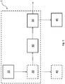
- reference number 1 generally indicates a production line in which an inspection is performed by means of the method and/or the apparatus according to the present invention.
- reference number is used for similar elements, even in the modified embodiments thereof.
- the production line 1 comprises at least one work station 10, at least one control station 20 and at least one vulcanisation station 30.
- the production line 1 can also comprise further stations, not illustrated in detail herein.
- control station 20 is provided downstream of the vulcanisation station 30 (with reference to the production flow indicated by the arrows), in order to control the tyres after vulcanisation.
- a further control station 20 (shown in dashed line) is operatively situated downstream of the work station 10 and upstream of the vulcanisation station 30 (in order, for example, to control the green tyres or the semi-finished products).
- a flow diagram of a process 200 for producing tyres in accordance with the present invention is schematically illustrated in figure 13 .
- the process 200 comprises at least one operation 210 for building green tyres (typically performed in the aforesaid work station 10), an operation 230 for vulcanising green tyres (typically performed in the aforesaid work station 30 subsequently to the building operation 210) and an operation 220 for controlling tyres or semi-finished products (typically performed in the aforesaid work station 20 subsequently at least to the building operation 210).
- the operation 220 for controlling tyres or semi-finished products provides for controlling n tyres or semi-finished products in a predefined time range, for example equal to about n times a cycle time.
- a flow of n tyres or semi-finished products is fed into the inlet of the control station 20.
- the cycle time can be comprised between about 20 s and about 120 s, more preferably between about 60 s and about 90 s.
- n tyres or semi-finished products will be sequentially processed, one after the other, by the same devices present in the control station 20.
- the control operation provides for lighting with a light radiation at least one portion of the surface of the tyre or semi-finished product; detecting the optical intensity of the light radiation reflected by the surface portion on a number N (with N equal to 1, preferably, or 2 or 3) of pairs of polarisation states belonging to a group of three pairs of polarisation states corresponding to three pairs of points on Poincaré sphere, the three pairs of points being located at the opposite ends of three respective diameters of the Poincaré sphere orthogonal to each other; calculating, on the surface portion, a number M (with M equal to 1, preferably, or 2 or 3) of values representative of an equivalent number of components of the Stokes vector belonging to a subgroup of three components of the Stokes vector comprising a second component, Q, equal to the, or a function of the, difference of the two optical intensities of the light radiation reflected by the surface portion on the first pair of polarisation states, a third component, U, equal to the, or a function of the, difference of the two optical
- control station 20 As a function of the control signal generated for each tyre or semi-finished product, the control station 20 establishes how to direct the n tyres or semi-finished products received in inlet:
- the n-k tyres forwarded outside the production flow are sent to a verification station 40 (outside the production line), where more in-depth analyses can be carried out to verify if the tyres must actually be definitively discarded.
- the production process consequently provides for a further verification operation 240 (carried out in the verification station 40) subsequent to the control operation only carried out on the n-k tyres or semi-finished products at least preliminarily deemed to be unsuitable.
- the control station 20 comprises at least one apparatus 100 for controlling tyres in a production line according to the method of the present invention.
- the apparatus 100 comprises a member 110 for moving a tyre 101 (shown in a dashed line in figure 2 ) having a horizontal support plane 120, such member adapted to rotate around an axis perpendicular to itself (in fig.2 perpendicular to the plane of the sheet), such axis coinciding with the cylindrical symmetry axis of the tyre.
- the apparatus 100 further comprises a source 130 adapted to emit a light radiation for lighting a surface portion of the tyre or semi-finished product supported on the support plane, and, at a distance from the source, a detection system 140 adapted to detect the optical intensity of the light radiation reflected by the surface portion on a number N, with N ranging from 1 to 3, of pairs of polarisation states belonging to a group of three pairs of polarisation states corresponding to three pairs of points on Poincaré sphere, the three pairs of points being located at the opposite ends of three respective diameters of the Poincaré sphere orthogonal to each other.
- the detection system comprises two digital cameras 141, each having a digital sensor adapted to detect the reflected light radiation, and each camera associated with a polariser 142 according to the present invention arranged upstream of the respective camera.
- the source 130 comprises, for example, two light sources 131 each associated with a respective camera.
- the two cameras are for example diametrically opposed with respect to the tyre.
- N a possible solution (not shown) provides for two further cameras, each with the respective polariser and the respective light source, diametrically opposite each other along a diameter (i.e.
- each group formed by a camera with the respective polariser and the respective light source can be moved in space in a manner so as to be able to sequentially control both the surface of the tread and that of the accessible sidewall.
- the apparatus 100 comprises a robotised arm 102 at whose free end the source 130 and the detection system 140 (represented only schematically) are rigidly mounted.
- the detection system 140 can comprise two cameras mounted side-by-side on the robotised arm with their respective polariser, or only one camera and, placed upstream before the same, a member (not shown) on which the two polarisers are mounted, such member configured for positioning only one polariser at a time in front of the camera.
- the apparatus 100 further comprises a processing unit 150 adapted to receive a detection signal from the detection system, and configured for carrying out the abovementioned operations.
- a tyre 101 is supported on the support plane 120 and subjected to a first complete rotation around the symmetry axis thereof in order to control the entire perimeter extension of the surface of the tread, and (possibly upon suitable repositioning of the light sources and the detection system) subjected to a second complete rotation around the symmetry axis thereof in order to control the entire perimeter extension of the surface of the accessible sidewall (the sidewall turned upward).
- the control station 20 for the tyres can comprise a pair of the aforesaid apparatuses 100 for controlling tyres in a production line and, interposed between the two apparatuses with reference to the production flow, a machine 50 for tilting the tyre around an axis orthogonal to the cylindrical symmetry axis of the tyre.
- a machine 50 for tilting the tyre around an axis orthogonal to the cylindrical symmetry axis of the tyre it is possible to control the two sidewalls of the tyre respectively in the two apparatuses.
- multiple apparatuses can also be present in accordance with the present invention and/or multiple pairs of apparatuses with a tilting machine interposed (which can be shared by multiple pairs of apparatuses).
- the flow of tyres or semi-finished products to be inspected can then be subdivided between the different control apparatuses.
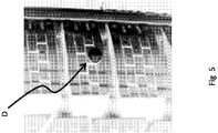
- Figures 5 to 12 show an example of implementation of the method in accordance with the present invention.
- Figure 5 shows a normal visible-light photograph in grey tones and without any polarisation filter of a surface portion of a tyre, on which a foreign metallic body D has been intentionally included.
- the surface portion is lit with white light.
- the axis of the objective of the camera is normal to the plane tangent to the envelope of the surface of the tread at the centre of the tread.
- the angle between the axis of the objective and the direction of propagation of the radiation incident on the surface portion is equal to about 90°.
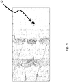
- Figures 6 , 7 and 8 show the respective image in black and white of the surface portion substantially coinciding with that of figure 5 obtained by associating each discrete point of the surface with a value representative respectively of the second, third and fourth Stokes component, Q, U and V, and after thresholding on the grey tones.
- the reference system for the main polarisation states is oriented with the horizontal and vertical linear polarisation axes, respectively parallel to the horizontal axis and vertical axis of the figures 6-12 .
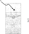
- Figures 9-12 show the respective image in black and white of the same surface portion obtained by associating each discrete point of the surface with a value representative respectively of the degree of linear polarisation, DOLP, of the degree of polarisation, DOP, of the degree of circular polarisation, DOCP and of the polarisation angle, PSI, and after suitable thresholding on the grey tones.
- DOLP degree of linear polarisation
- DOP degree of polarisation
- DOCP degree of circular polarisation
- PSI polarisation angle
- the flaw D clearly stands out in all the images, in particular in those of figures 6 , 9 , 10 and 12 .
- the images, and/or for even more reason the respective detection signals can be subjected to suitable processing algorithms (such as the algorithms that actuate a median filter or those known as "blob detection", which are able to recognise and isolate parts of the image with high pixel densities) in order to distinguish the flaw from the rest of the image.
- suitable processing algorithms such as the algorithms that actuate a median filter or those known as "blob detection", which are able to recognise and isolate parts of the image with high pixel densities
Landscapes
- Physics & Mathematics (AREA)
- General Physics & Mathematics (AREA)
- General Health & Medical Sciences (AREA)
- Chemical & Material Sciences (AREA)
- Analytical Chemistry (AREA)
- Biochemistry (AREA)
- Life Sciences & Earth Sciences (AREA)
- Health & Medical Sciences (AREA)
- Immunology (AREA)
- Pathology (AREA)
- Investigating Materials By The Use Of Optical Means Adapted For Particular Applications (AREA)
- Investigating Or Analysing Materials By Optical Means (AREA)
- Length Measuring Devices By Optical Means (AREA)
Claims (15)
- Procédé de contrôle de pneus ou de produits semi-finis dans une chaîne de production de pneus (1), le procédé comprenant le fait :- d'éclairer avec un rayonnement lumineux au moins une partie de la surface d'un pneu ou d'un produit semi-fini (101) à inspecter ;- de détecter l'intensité optique du rayonnement lumineux réfléchi par ladite partie de surface sur un nombre N de paires d'états de polarisation appartenant à un groupe de trois paires d'états de polarisation correspondant à trois paires de points sur la sphère de Poincaré, les trois paires de points étant situées au niveau des extrémités opposées de trois diamètres respectifs de la sphère de Poincaré orthogonaux entre eux, ledit nombre N étant égal à 1 ou 2 ou 3 ;- de calculer, sur ladite partie de surface, un nombre M de valeurs représentant un nombre équivalent de composantes du vecteur de Stokes appartenant à un sous-groupe de trois composantes du vecteur de Stokes comprenant une deuxième composante, Q, égale à, ou une fonction de, la différence des deux intensités optiques du rayonnement lumineux réfléchi par la partie de surface sur la première paire d'états de polarisation, une troisième composante, U, égale à, ou une fonction de, la différence des deux intensités optiques du rayonnement lumineux réfléchi par la partie de surface sur la deuxième paire d'états de polarisation et une quatrième composante, V, égale à, ou une fonction de, la différence des deux intensités optiques du rayonnement lumineux réfléchi par la partie de surface sur la troisième paire d'états de polarisation, où ledit nombre M est égal à 1 ou 2 ou 3 ;- de générer, pour ladite partie de surface, un signal de contrôle respectif représentant chacune desdites valeurs représentant lesdites composantes du vecteur de Stokes ;- d'analyser ledit signal de contrôle respectif sur ladite partie de surface pour détecter la présence éventuelle de défauts de surface.
- Procédé tel que revendiqué dans la revendication 1, dans lequel la première paire d'états de polarisation est constituée de la polarisation linéaire horizontale et verticale, la deuxième paire d'états de polarisation est constituée de la polarisation linéaire à +45° et -45° et la troisième paire d'états de polarisation est constituée de la polarisation circulaire droite et gauche,
dans lequel l'intensité optique du rayonnement lumineux réfléchi par ladite partie de surface sur la première paire d'états de polarisation est détectée en faisant passer le rayonnement lumineux réfléchi à travers un polariseur linéaire aligné le long de l'axe horizontal et à travers un polariseur linéaire aligné le long de l'axe vertical, respectivement,
et/ou dans lequel l'intensité optique du rayonnement lumineux réfléchi par ladite partie de surface sur la deuxième paire d'états de polarisation est détectée en faisant passer le rayonnement lumineux réfléchi à travers un polariseur linéaire aligné à +45° par rapport à l'horizontale et à travers un polariseur linéaire aligné à -45° par rapport à l'horizontale, respectivement,
et/ou dans lequel l'intensité optique du rayonnement lumineux réfléchi par ladite partie de surface sur la troisième paire d'états de polarisation est détectée, en ce qui concerne la polarisation circulaire droite, en faisant passer le rayonnement lumineux réfléchi à travers une lame quart d'onde avec son axe rapide positionné le long de l'axe horizontal suivi, en aval de la lame par rapport à la direction de propagation du rayonnement lumineux, d'un polariseur linéaire aligné à +45° par rapport à l'axe horizontal et, en ce qui concerne la polarisation circulaire gauche, en faisant passer le rayonnement lumineux réfléchi à travers une lame quart d'onde avec son axe rapide positionné le long de l'axe horizontal suivi d'un polariseur linéaire aligné à -45° par rapport à l'axe horizontal. - Procédé tel que revendiqué dans l'une quelconque des revendications précédentes, dans lequel ledit nombre N est égal à 1 et ledit nombre M est égal à 1 et dans lequel la paire d'états de polarisation sur laquelle l'intensité optique du rayonnement lumineux réfléchi est détectée est la première paire et ladite valeur représentant les composantes de Stokes représente la deuxième composante de Stokes, Q.
- Procédé tel que revendiqué dans l'une quelconque des revendications précédentes, dans lequel il est en outre prévu de calculer, sur ladite partie de surface, une valeur supplémentaire représentant une première composante du vecteur de Stokes, I, égale à, ou une fonction de, la somme des deux intensités optiques du rayonnement lumineux réfléchi par la partie de surface sur la première paire d'états de polarisation.
- Procédé tel que revendiqué dans la revendication 4, dans lequel ledit nombre N de paires d'états de polarisation est égal à 2 ou 3 et ledit nombre M est égal à 2 ou 3, et dans lequel lesdites M valeurs représentant un nombre équivalent de composantes de Stokes comprennent la valeur représentant la deuxième composante, Q et dans lequel il est prévu de calculer, sur ladite partie de surface, en fonction desdites M valeurs représentant les composantes de Stokes et de ladite valeur supplémentaire représentant la première composante de Stokes, au moins un premier paramètre de polarisation, de préférence également au moins un deuxième paramètre de polarisation, plus préférentiellement également un troisième paramètre de polarisation, appartenant à un groupe de paramètres de polarisation constitué d'un degré de polarisation linéaire, DOLP=sqrt (Q2+U2) /I, d'un angle de polarisation, PSI=0,5*atan(U/Q) et d'un degré de polarisation circulaire, DOCP=V/I.
- Procédé tel que revendiqué dans la revendication 5 dans lequel ledit nombre N est égal à trois et ledit nombre M est égal à trois, et dans lequel le procédé comprend le calcul, sur ladite partie de surface, en fonction desdites M valeurs représentant les composantes de Stokes et de ladite valeur supplémentaire représentant la première composante de Stokes, d'un degré de polarisation, DOP=sqrt (Q2+U2+V2) /I.
- Procédé tel que revendiqué dans l'une quelconque des revendications précédentes, dans lequel le rayonnement lumineux qui éclaire au moins une partie de surface du pneu ou du produit semi-fini n'est pas polarisé ou il est au moins en partie non polarisé.
- Procédé tel que revendiqué dans l'une quelconque des revendications précédentes, dans lequel, dans l'opération d'éclairage d'une partie de la surface, l'angle formé entre la direction de propagation du rayonnement lumineux qui éclaire la surface et la normale au plan localement tangent à l'enveloppe de la partie de surface est supérieur ou égal à 30°, de préférence supérieur ou égal à 45°.
- Procédé tel que revendiqué dans l'une quelconque des revendications précédentes, dans lequel il est prévu de détecter l'intensité optique du rayonnement lumineux réfléchi au moyen d'au moins une caméra numérique ayant un capteur optique numérique adapté pour détecter ledit rayonnement lumineux réfléchi et un objectif optique avec un axe de celui-ci, dans lequel l'angle formé entre ledit axe et la normale au plan localement tangent à l'enveloppe de la partie de surface est inférieur ou égal à 50°, de préférence inférieur ou égal à 30°, et dans lequel l'angle formé par la direction de propagation du rayonnement lumineux qui éclaire la partie de la surface et ledit axe de l'objectif de la caméra est supérieur ou égal à 40°, de préférence supérieur ou égal à 60°.
- Procédé tel que revendiqué dans l'une quelconque des revendications précédentes, comprenant en outre la discrétisation de ladite partie de surface en un nombre fini de points, dans lequel l'opération/les opérations pour détecter l'intensité optique et/ou générer un signal de détection respectif et/ou calculer un nombre M de valeurs et/ou calculer les paramètres de polarisation et/ou générer un signal de contrôle respectif et/ou analyser le signal de contrôle respectif, est/sont effectuée(s) pour chaque point de la partie de surface, le procédé comprenant en outre la création, pour chacune desdites M valeurs représentant les composantes de Stokes et/ou pour chacun desdits paramètres de polarisation, d'une image de ladite partie de surface dans laquelle chaque point de la surface est affiché en fonction de la valeur respective de ladite valeur représentative et/ou, respectivement, dudit paramètre de polarisation.
- Processus (200) de production de pneus comprenant au moins une opération (210) de construction de pneus crus, une opération (230) de vulcanisation de pneus crus et une opération (220) de contrôle de pneus ou de produits semi-finis selon le procédé tel que revendiqué dans l'une quelconque des revendications précédentes.
- Appareil (100) de contrôle de pneus ou de produits semi-finis (101) dans une chaîne de production de pneus (1), l'appareil comprenant :- un élément (110) pour déplacer un pneu ou un produit semi-fini ayant un plan de support (120), de préférence horizontal, adapté pour tourner autour d'un axe perpendiculairement à lui-même ;- une source (130) adaptée pour émettre un rayonnement lumineux pour éclairer une partie de surface du pneu ou du produit semi-fini, lorsqu'il se trouve sur le plan de support, et, à distance de ladite source, un système de détection (140) adapté pour détecter l'intensité optique du rayonnement lumineux réfléchi par ladite partie de surface sur un nombre N de paires d'états de polarisation appartenant à un groupe de trois paires d'états de polarisation correspondant à trois paires de points sur la sphère de Poincaré, les trois paires de points étant situées au niveau des extrémités opposées de trois diamètres respectifs de la sphère de Poincaré orthogonaux entre eux, ledit nombre N étant égal à 1 ou 2 ou 3, et pour générer un signal de détection respectif ; et- une unité de traitement (150) adaptée pour recevoir, à partir du système de détection, ledit signal de détection et configurée pour les fonctions suivantes consistant :- à calculer, sur ladite partie de surface, un nombre M de valeurs représentant un nombre équivalent de composantes du vecteur de Stokes appartenant à un sous-groupe de trois composantes du vecteur de Stokes comprenant une deuxième composante, Q, égale à, ou une fonction de, la différence des deux intensités optiques du rayonnement lumineux réfléchi par la partie de surface sur la première paire d'états de polarisation, une troisième composante, U, égale à, ou une fonction de, la différence des deux intensités optiques du rayonnement lumineux réfléchi par la partie de surface sur la deuxième paire d'états de polarisation et une quatrième composante, V, égale à, ou une fonction de, la différence des deux intensités optiques du rayonnement lumineux réfléchi par la partie de surface sur la troisième paire d'états de polarisation, où ledit nombre M est égal à 1 ou 2 ou 3 ;- à générer, pour ladite partie de surface, un signal de contrôle respectif représentant chacune desdites M valeurs représentant lesdites composantes du vecteur de Stokes et- à analyser ledit signal de contrôle respectif sur ladite partie de surface pour détecter la présence éventuelle de défauts de surface.
- Appareil tel que revendiqué dans la revendication précédente, dans lequel ledit système de détection comprend au moins une caméra numérique (141) et un nombre 2N de polariseurs (142), chacun structuré pour projeter le rayonnement lumineux réfléchi sur un état respectif appartenant auxdites N paires d'états de polarisation, où la totalité ou une partie des polariseurs 2N peut être positionnée en amont de la caméra par rapport à la direction de propagation du rayonnement lumineux réfléchi, d'une manière mutuellement exclusive.
- Appareil tel que revendiqué dans la revendication 12, dans lequel ledit système de détection comprend un nombre 2N de polariseurs (142), chacun structuré pour projeter le rayonnement lumineux réfléchi sur un état respectif appartenant auxdites N paires d'états de polarisation, où le système de détection comprend un nombre 2N de caméras numériques, chacune munie d'un polariseur respectif différent des autres polariseurs,
dans lequel les 2N caméras sont réparties de manière angulairement uniforme autour de la circonférence du pneu ou du produit semi-fini, ladite source comprenant un nombre 2N de sources lumineuses (131) associées chacune à une caméra respective,
ou dans lequel les 2N caméras sont positionnées dans une position angulaire unique par rapport à l'extension du périmètre du pneu ou du produit semi-fini, et utilisent la même source lumineuse unique. - Chaîne (1) de production de pneus comprenant au moins un poste de travail (10), c'est-à-dire une zone structurée et configurée pour réaliser au moins une opération de construction de pneus crus, au moins un poste de vulcanisation (30), c'est-à-dire une zone structurée et configurée pour réaliser une opération de vulcanisation de pneus crus, et au moins un poste de contrôle (20) comprenant un appareil (100) pour contrôler des pneus ou des produits semi-finis tel que revendiqué dans l'une quelconque des revendications 12 à 14, où le poste de contrôle de pneus comprend une paire desdits appareils (100) pour contrôler des pneus dans une chaîne de production et, interposée entre les deux appareils en référence au flux de production, une machine (50) pour incliner le pneu autour d'un axe orthogonal à l'axe de symétrie cylindrique du pneu.
Applications Claiming Priority (3)
| Application Number | Priority Date | Filing Date | Title |
|---|---|---|---|
| ITMI20122218 | 2012-12-21 | ||
| US201361806153P | 2013-03-28 | 2013-03-28 | |
| PCT/IB2013/061016 WO2014097133A1 (fr) | 2012-12-21 | 2013-12-17 | Procédé et appareil de contrôle de pneumatiques ou de produits semi-finis associés sur une ligne de production |
Publications (2)
| Publication Number | Publication Date |
|---|---|
| EP2936111A1 EP2936111A1 (fr) | 2015-10-28 |
| EP2936111B1 true EP2936111B1 (fr) | 2021-08-04 |
Family
ID=47720662
Family Applications (1)
| Application Number | Title | Priority Date | Filing Date |
|---|---|---|---|
| EP13828823.8A Active EP2936111B1 (fr) | 2012-12-21 | 2013-12-17 | Procédé et appareil de contrôle de pneumatiques ou de produits semi-finis associés sur une ligne de production |
Country Status (4)
| Country | Link |
|---|---|
| EP (1) | EP2936111B1 (fr) |
| CN (1) | CN105190277B (fr) |
| RU (1) | RU2642169C2 (fr) |
| WO (1) | WO2014097133A1 (fr) |
Families Citing this family (5)
| Publication number | Priority date | Publication date | Assignee | Title |
|---|---|---|---|---|
| KR102534392B1 (ko) * | 2014-12-22 | 2023-05-19 | 피렐리 타이어 소시에떼 퍼 아찌오니 | 생산라인에서 타이어를 제어하기 위한 기기 |
| EP3237837B1 (fr) | 2014-12-22 | 2020-02-19 | Pirelli Tyre S.p.A. | Procédé et appareil pour contrôler des pneus dans une chaîne de production |
| BR112018012559B1 (pt) * | 2015-12-28 | 2022-03-03 | Pirelli Tyre S.P.A | Método para gerenciamento de um aparelho para verificação de pneu, e, aparelho para verificação de pneu |
| EP3397936B1 (fr) * | 2015-12-28 | 2020-02-26 | Pirelli Tyre S.p.A. | Dispositif de controle de pneus |
| DE102018125450A1 (de) * | 2018-10-15 | 2020-04-16 | HELLA GmbH & Co. KGaA | Verfahren zum Ermitteln mindestens eines Relativparameters zumindest der Lage oder der Bewegung eines ersten Fahrzeugs in Relation zu einem zweiten Fahrzeug |
Family Cites Families (10)
| Publication number | Priority date | Publication date | Assignee | Title |
|---|---|---|---|---|
| JP2003240521A (ja) * | 2002-02-21 | 2003-08-27 | Bridgestone Corp | 被検体の外観・形状検査方法とその装置、及び、被検体の外観・形状検出装置 |
| US7808637B2 (en) * | 2003-11-26 | 2010-10-05 | Axometrics, Incorporated | Method and apparatus for determining liquid crystal cell parameters from full mueller matrix measurements |
| WO2007124930A1 (fr) * | 2006-04-28 | 2007-11-08 | Micronic Laser Systems Ab | Procede et appareil pour enregistrer des images et etudier des surfaces |
| EP2084488B1 (fr) * | 2006-10-20 | 2017-03-22 | Bioaxial | Dispositifs optiques fondés sur la diffraction conique interne |
| JP5104004B2 (ja) * | 2007-04-19 | 2012-12-19 | Jfeスチール株式会社 | 表面欠陥検査装置および表面欠陥検査方法 |
| US8600243B2 (en) * | 2008-04-18 | 2013-12-03 | Purdue Research Foundation | Polarization mode dispersion compensation |
| JP5312182B2 (ja) | 2009-04-30 | 2013-10-09 | 株式会社ブリヂストン | タイヤ内面検査装置 |
| JP5837283B2 (ja) * | 2010-03-18 | 2015-12-24 | 株式会社ブリヂストン | タイヤの外観検査方法および外観検査装置 |
| CN102313749B (zh) * | 2010-06-30 | 2013-03-06 | 软控股份有限公司 | 工程机械轮胎激光散斑检测装置及其方法 |
| CN102183529B (zh) * | 2011-03-22 | 2013-10-16 | 广州华工百川科技股份有限公司 | 便携式激光散斑轮胎无损检测仪及其检测方法 |
-
2013
- 2013-12-17 WO PCT/IB2013/061016 patent/WO2014097133A1/fr not_active Ceased
- 2013-12-17 RU RU2015128626A patent/RU2642169C2/ru active
- 2013-12-17 EP EP13828823.8A patent/EP2936111B1/fr active Active
- 2013-12-17 CN CN201380066568.7A patent/CN105190277B/zh active Active
Also Published As
| Publication number | Publication date |
|---|---|
| CN105190277A (zh) | 2015-12-23 |
| EP2936111A1 (fr) | 2015-10-28 |
| CN105190277B (zh) | 2018-04-10 |
| RU2015128626A (ru) | 2017-01-30 |
| WO2014097133A1 (fr) | 2014-06-26 |
| RU2642169C2 (ru) | 2018-01-24 |
Similar Documents
| Publication | Publication Date | Title |
|---|---|---|
| EP2936111B1 (fr) | Procédé et appareil de contrôle de pneumatiques ou de produits semi-finis associés sur une ligne de production | |
| RU2763417C2 (ru) | Система и связанный с ней способ обнаружения мелких дефектов на/в листе стекла на технологической линии | |
| US10697857B2 (en) | Method and apparatus for checking tyres in a production line | |
| US10697762B2 (en) | Apparatus for controlling tyres in a production line | |
| WO2011159280A2 (fr) | Détection d'anomalie de surface de pneu | |
| WO2017109688A1 (fr) | Appareil et procédé permettant de vérifier des pneus | |
| EP3365651B1 (fr) | Station et procédé de vérification de pneus | |
| KR101299571B1 (ko) | 타이어 검사방법 | |
| EP3391013B1 (fr) | Appareil et procédé pour l'analyse de pneus | |
| KR102473365B1 (ko) | 머신러닝을 이용한 타이어 검사 시스템 및 이를 이용한 타이어 검사 방법 | |
| EP3397463B1 (fr) | Procédé de gestion d'un appareil de contrôle de pneu et appareil de contrôle de pneu conçu pour fonctionner selon ce procédé | |
| JP5644990B2 (ja) | 長尺物の外観検査方法及びその装置 | |
| BR112015013597B1 (pt) | método e aparelho para controlar pneus ou produtos semi-acabados, e, processo e linha de produção de pneu | |
| JP2016001165A (ja) | タイヤの外観検査方法 |
Legal Events
| Date | Code | Title | Description |
|---|---|---|---|
| PUAI | Public reference made under article 153(3) epc to a published international application that has entered the european phase |
Free format text: ORIGINAL CODE: 0009012 |
|
| 17P | Request for examination filed |
Effective date: 20150521 |
|
| AK | Designated contracting states |
Kind code of ref document: A1 Designated state(s): AL AT BE BG CH CY CZ DE DK EE ES FI FR GB GR HR HU IE IS IT LI LT LU LV MC MK MT NL NO PL PT RO RS SE SI SK SM TR |
|
| AX | Request for extension of the european patent |
Extension state: BA ME |
|
| RAP1 | Party data changed (applicant data changed or rights of an application transferred) |
Owner name: PIRELLI TYRE S.P.A. |
|
| DAX | Request for extension of the european patent (deleted) | ||
| GRAP | Despatch of communication of intention to grant a patent |
Free format text: ORIGINAL CODE: EPIDOSNIGR1 |
|
| STAA | Information on the status of an ep patent application or granted ep patent |
Free format text: STATUS: GRANT OF PATENT IS INTENDED |
|
| INTG | Intention to grant announced |
Effective date: 20210324 |
|
| GRAS | Grant fee paid |
Free format text: ORIGINAL CODE: EPIDOSNIGR3 |
|
| GRAA | (expected) grant |
Free format text: ORIGINAL CODE: 0009210 |
|
| STAA | Information on the status of an ep patent application or granted ep patent |
Free format text: STATUS: THE PATENT HAS BEEN GRANTED |
|
| AK | Designated contracting states |
Kind code of ref document: B1 Designated state(s): AL AT BE BG CH CY CZ DE DK EE ES FI FR GB GR HR HU IE IS IT LI LT LU LV MC MK MT NL NO PL PT RO RS SE SI SK SM TR |
|
| REG | Reference to a national code |
Ref country code: GB Ref legal event code: FG4D |
|
| RIN1 | Information on inventor provided before grant (corrected) |
Inventor name: BOFFA, VINCENZO Inventor name: GALLO, MARCO Inventor name: MONTRUCCHIO, BARTOLOMEO |
|
| REG | Reference to a national code |
Ref country code: AT Ref legal event code: REF Ref document number: 1417450 Country of ref document: AT Kind code of ref document: T Effective date: 20210815 |
|
| REG | Reference to a national code |
Ref country code: CH Ref legal event code: EP |
|
| REG | Reference to a national code |
Ref country code: DE Ref legal event code: R096 Ref document number: 602013078673 Country of ref document: DE |
|
| REG | Reference to a national code |
Ref country code: IE Ref legal event code: FG4D |
|
| REG | Reference to a national code |
Ref country code: LT Ref legal event code: MG9D |
|
| REG | Reference to a national code |
Ref country code: NL Ref legal event code: MP Effective date: 20210804 |
|
| REG | Reference to a national code |
Ref country code: AT Ref legal event code: MK05 Ref document number: 1417450 Country of ref document: AT Kind code of ref document: T Effective date: 20210804 |
|
| PG25 | Lapsed in a contracting state [announced via postgrant information from national office to epo] |
Ref country code: HR Free format text: LAPSE BECAUSE OF FAILURE TO SUBMIT A TRANSLATION OF THE DESCRIPTION OR TO PAY THE FEE WITHIN THE PRESCRIBED TIME-LIMIT Effective date: 20210804 Ref country code: RS Free format text: LAPSE BECAUSE OF FAILURE TO SUBMIT A TRANSLATION OF THE DESCRIPTION OR TO PAY THE FEE WITHIN THE PRESCRIBED TIME-LIMIT Effective date: 20210804 Ref country code: SE Free format text: LAPSE BECAUSE OF FAILURE TO SUBMIT A TRANSLATION OF THE DESCRIPTION OR TO PAY THE FEE WITHIN THE PRESCRIBED TIME-LIMIT Effective date: 20210804 Ref country code: LT Free format text: LAPSE BECAUSE OF FAILURE TO SUBMIT A TRANSLATION OF THE DESCRIPTION OR TO PAY THE FEE WITHIN THE PRESCRIBED TIME-LIMIT Effective date: 20210804 Ref country code: BG Free format text: LAPSE BECAUSE OF FAILURE TO SUBMIT A TRANSLATION OF THE DESCRIPTION OR TO PAY THE FEE WITHIN THE PRESCRIBED TIME-LIMIT Effective date: 20211104 Ref country code: AT Free format text: LAPSE BECAUSE OF FAILURE TO SUBMIT A TRANSLATION OF THE DESCRIPTION OR TO PAY THE FEE WITHIN THE PRESCRIBED TIME-LIMIT Effective date: 20210804 Ref country code: PT Free format text: LAPSE BECAUSE OF FAILURE TO SUBMIT A TRANSLATION OF THE DESCRIPTION OR TO PAY THE FEE WITHIN THE PRESCRIBED TIME-LIMIT Effective date: 20211206 Ref country code: NO Free format text: LAPSE BECAUSE OF FAILURE TO SUBMIT A TRANSLATION OF THE DESCRIPTION OR TO PAY THE FEE WITHIN THE PRESCRIBED TIME-LIMIT Effective date: 20211104 Ref country code: FI Free format text: LAPSE BECAUSE OF FAILURE TO SUBMIT A TRANSLATION OF THE DESCRIPTION OR TO PAY THE FEE WITHIN THE PRESCRIBED TIME-LIMIT Effective date: 20210804 Ref country code: ES Free format text: LAPSE BECAUSE OF FAILURE TO SUBMIT A TRANSLATION OF THE DESCRIPTION OR TO PAY THE FEE WITHIN THE PRESCRIBED TIME-LIMIT Effective date: 20210804 |
|
| PG25 | Lapsed in a contracting state [announced via postgrant information from national office to epo] |
Ref country code: PL Free format text: LAPSE BECAUSE OF FAILURE TO SUBMIT A TRANSLATION OF THE DESCRIPTION OR TO PAY THE FEE WITHIN THE PRESCRIBED TIME-LIMIT Effective date: 20210804 Ref country code: LV Free format text: LAPSE BECAUSE OF FAILURE TO SUBMIT A TRANSLATION OF THE DESCRIPTION OR TO PAY THE FEE WITHIN THE PRESCRIBED TIME-LIMIT Effective date: 20210804 Ref country code: GR Free format text: LAPSE BECAUSE OF FAILURE TO SUBMIT A TRANSLATION OF THE DESCRIPTION OR TO PAY THE FEE WITHIN THE PRESCRIBED TIME-LIMIT Effective date: 20211105 |
|
| PG25 | Lapsed in a contracting state [announced via postgrant information from national office to epo] |
Ref country code: NL Free format text: LAPSE BECAUSE OF FAILURE TO SUBMIT A TRANSLATION OF THE DESCRIPTION OR TO PAY THE FEE WITHIN THE PRESCRIBED TIME-LIMIT Effective date: 20210804 |
|
| PG25 | Lapsed in a contracting state [announced via postgrant information from national office to epo] |
Ref country code: DK Free format text: LAPSE BECAUSE OF FAILURE TO SUBMIT A TRANSLATION OF THE DESCRIPTION OR TO PAY THE FEE WITHIN THE PRESCRIBED TIME-LIMIT Effective date: 20210804 |
|
| REG | Reference to a national code |
Ref country code: DE Ref legal event code: R097 Ref document number: 602013078673 Country of ref document: DE |
|
| PG25 | Lapsed in a contracting state [announced via postgrant information from national office to epo] |
Ref country code: SM Free format text: LAPSE BECAUSE OF FAILURE TO SUBMIT A TRANSLATION OF THE DESCRIPTION OR TO PAY THE FEE WITHIN THE PRESCRIBED TIME-LIMIT Effective date: 20210804 Ref country code: SK Free format text: LAPSE BECAUSE OF FAILURE TO SUBMIT A TRANSLATION OF THE DESCRIPTION OR TO PAY THE FEE WITHIN THE PRESCRIBED TIME-LIMIT Effective date: 20210804 Ref country code: RO Free format text: LAPSE BECAUSE OF FAILURE TO SUBMIT A TRANSLATION OF THE DESCRIPTION OR TO PAY THE FEE WITHIN THE PRESCRIBED TIME-LIMIT Effective date: 20210804 Ref country code: EE Free format text: LAPSE BECAUSE OF FAILURE TO SUBMIT A TRANSLATION OF THE DESCRIPTION OR TO PAY THE FEE WITHIN THE PRESCRIBED TIME-LIMIT Effective date: 20210804 Ref country code: CZ Free format text: LAPSE BECAUSE OF FAILURE TO SUBMIT A TRANSLATION OF THE DESCRIPTION OR TO PAY THE FEE WITHIN THE PRESCRIBED TIME-LIMIT Effective date: 20210804 Ref country code: AL Free format text: LAPSE BECAUSE OF FAILURE TO SUBMIT A TRANSLATION OF THE DESCRIPTION OR TO PAY THE FEE WITHIN THE PRESCRIBED TIME-LIMIT Effective date: 20210804 |
|
| PLBE | No opposition filed within time limit |
Free format text: ORIGINAL CODE: 0009261 |
|
| STAA | Information on the status of an ep patent application or granted ep patent |
Free format text: STATUS: NO OPPOSITION FILED WITHIN TIME LIMIT |
|
| 26N | No opposition filed |
Effective date: 20220506 |
|
| PG25 | Lapsed in a contracting state [announced via postgrant information from national office to epo] |
Ref country code: MC Free format text: LAPSE BECAUSE OF FAILURE TO SUBMIT A TRANSLATION OF THE DESCRIPTION OR TO PAY THE FEE WITHIN THE PRESCRIBED TIME-LIMIT Effective date: 20210804 |
|
| REG | Reference to a national code |
Ref country code: CH Ref legal event code: PL |
|
| GBPC | Gb: european patent ceased through non-payment of renewal fee |
Effective date: 20211217 |
|
| PG25 | Lapsed in a contracting state [announced via postgrant information from national office to epo] |
Ref country code: SI Free format text: LAPSE BECAUSE OF FAILURE TO SUBMIT A TRANSLATION OF THE DESCRIPTION OR TO PAY THE FEE WITHIN THE PRESCRIBED TIME-LIMIT Effective date: 20210804 |
|
| REG | Reference to a national code |
Ref country code: BE Ref legal event code: MM Effective date: 20211231 |
|
| PG25 | Lapsed in a contracting state [announced via postgrant information from national office to epo] |
Ref country code: LU Free format text: LAPSE BECAUSE OF NON-PAYMENT OF DUE FEES Effective date: 20211217 Ref country code: IE Free format text: LAPSE BECAUSE OF NON-PAYMENT OF DUE FEES Effective date: 20211217 Ref country code: GB Free format text: LAPSE BECAUSE OF NON-PAYMENT OF DUE FEES Effective date: 20211217 |
|
| PG25 | Lapsed in a contracting state [announced via postgrant information from national office to epo] |
Ref country code: BE Free format text: LAPSE BECAUSE OF NON-PAYMENT OF DUE FEES Effective date: 20211231 |
|
| PG25 | Lapsed in a contracting state [announced via postgrant information from national office to epo] |
Ref country code: LI Free format text: LAPSE BECAUSE OF NON-PAYMENT OF DUE FEES Effective date: 20211231 Ref country code: CH Free format text: LAPSE BECAUSE OF NON-PAYMENT OF DUE FEES Effective date: 20211231 |
|
| PG25 | Lapsed in a contracting state [announced via postgrant information from national office to epo] |
Ref country code: HU Free format text: LAPSE BECAUSE OF FAILURE TO SUBMIT A TRANSLATION OF THE DESCRIPTION OR TO PAY THE FEE WITHIN THE PRESCRIBED TIME-LIMIT; INVALID AB INITIO Effective date: 20131217 |
|
| PG25 | Lapsed in a contracting state [announced via postgrant information from national office to epo] |
Ref country code: CY Free format text: LAPSE BECAUSE OF FAILURE TO SUBMIT A TRANSLATION OF THE DESCRIPTION OR TO PAY THE FEE WITHIN THE PRESCRIBED TIME-LIMIT Effective date: 20210804 |
|
| PG25 | Lapsed in a contracting state [announced via postgrant information from national office to epo] |
Ref country code: MK Free format text: LAPSE BECAUSE OF FAILURE TO SUBMIT A TRANSLATION OF THE DESCRIPTION OR TO PAY THE FEE WITHIN THE PRESCRIBED TIME-LIMIT Effective date: 20210804 |
|
| PG25 | Lapsed in a contracting state [announced via postgrant information from national office to epo] |
Ref country code: MT Free format text: LAPSE BECAUSE OF FAILURE TO SUBMIT A TRANSLATION OF THE DESCRIPTION OR TO PAY THE FEE WITHIN THE PRESCRIBED TIME-LIMIT Effective date: 20210804 |
|
| PGFP | Annual fee paid to national office [announced via postgrant information from national office to epo] |
Ref country code: FR Payment date: 20241226 Year of fee payment: 12 |
|
| PGFP | Annual fee paid to national office [announced via postgrant information from national office to epo] |
Ref country code: IT Payment date: 20241218 Year of fee payment: 12 |
|
| PGFP | Annual fee paid to national office [announced via postgrant information from national office to epo] |
Ref country code: DE Payment date: 20241227 Year of fee payment: 12 |
|
| PG25 | Lapsed in a contracting state [announced via postgrant information from national office to epo] |
Ref country code: TR Free format text: LAPSE BECAUSE OF FAILURE TO SUBMIT A TRANSLATION OF THE DESCRIPTION OR TO PAY THE FEE WITHIN THE PRESCRIBED TIME-LIMIT Effective date: 20210804 |