EP2936148B1 - Système et procédé pour détecter un analyte dans un échantillon corporel fluidique - Google Patents
Système et procédé pour détecter un analyte dans un échantillon corporel fluidique Download PDFInfo
- Publication number
- EP2936148B1 EP2936148B1 EP13815806.8A EP13815806A EP2936148B1 EP 2936148 B1 EP2936148 B1 EP 2936148B1 EP 13815806 A EP13815806 A EP 13815806A EP 2936148 B1 EP2936148 B1 EP 2936148B1
- Authority
- EP
- European Patent Office
- Prior art keywords
- continuity
- function pins
- controller
- sample
- test strip
- Prior art date
- Legal status (The legal status is an assumption and is not a legal conclusion. Google has not performed a legal analysis and makes no representation as to the accuracy of the status listed.)
- Not-in-force
Links
Images


Classifications
-
- H—ELECTRICITY
- H01—ELECTRIC ELEMENTS
- H01R—ELECTRICALLY-CONDUCTIVE CONNECTIONS; STRUCTURAL ASSOCIATIONS OF A PLURALITY OF MUTUALLY-INSULATED ELECTRICAL CONNECTING ELEMENTS; COUPLING DEVICES; CURRENT COLLECTORS
- H01R12/00—Structural associations of a plurality of mutually-insulated electrical connecting elements, specially adapted for printed circuits, e.g. printed circuit boards [PCB], flat or ribbon cables, or like generally planar structures, e.g. terminal strips, terminal blocks; Coupling devices specially adapted for printed circuits, flat or ribbon cables, or like generally planar structures; Terminals specially adapted for contact with, or insertion into, printed circuits, flat or ribbon cables, or like generally planar structures
- H01R12/50—Fixed connections
- H01R12/59—Fixed connections for flexible printed circuits, flat or ribbon cables or like structures
- H01R12/61—Fixed connections for flexible printed circuits, flat or ribbon cables or like structures connecting to flexible printed circuits, flat or ribbon cables or like structures
- H01R12/613—Fixed connections for flexible printed circuits, flat or ribbon cables or like structures connecting to flexible printed circuits, flat or ribbon cables or like structures by means of interconnecting elements
-
- G—PHYSICS
- G01—MEASURING; TESTING
- G01N—INVESTIGATING OR ANALYSING MATERIALS BY DETERMINING THEIR CHEMICAL OR PHYSICAL PROPERTIES
- G01N33/00—Investigating or analysing materials by specific methods not covered by groups G01N1/00 - G01N31/00
- G01N33/48—Biological material, e.g. blood, urine; Haemocytometers
- G01N33/483—Physical analysis of biological material
- G01N33/487—Physical analysis of biological material of liquid biological material
- G01N33/4875—Details of handling test elements, e.g. dispensing or storage, not specific to a particular test method
- G01N33/48771—Coding of information, e.g. calibration data, lot number
-
- H—ELECTRICITY
- H01—ELECTRIC ELEMENTS
- H01R—ELECTRICALLY-CONDUCTIVE CONNECTIONS; STRUCTURAL ASSOCIATIONS OF A PLURALITY OF MUTUALLY-INSULATED ELECTRICAL CONNECTING ELEMENTS; COUPLING DEVICES; CURRENT COLLECTORS
- H01R12/00—Structural associations of a plurality of mutually-insulated electrical connecting elements, specially adapted for printed circuits, e.g. printed circuit boards [PCB], flat or ribbon cables, or like generally planar structures, e.g. terminal strips, terminal blocks; Coupling devices specially adapted for printed circuits, flat or ribbon cables, or like generally planar structures; Terminals specially adapted for contact with, or insertion into, printed circuits, flat or ribbon cables, or like generally planar structures
- H01R12/70—Coupling devices
- H01R12/71—Coupling devices for rigid printing circuits or like structures
- H01R12/712—Coupling devices for rigid printing circuits or like structures co-operating with the surface of the printed circuit or with a coupling device exclusively provided on the surface of the printed circuit
- H01R12/714—Coupling devices for rigid printing circuits or like structures co-operating with the surface of the printed circuit or with a coupling device exclusively provided on the surface of the printed circuit with contacts abutting directly the printed circuit; Button contacts therefore provided on the printed circuit
-
- H—ELECTRICITY
- H01—ELECTRIC ELEMENTS
- H01R—ELECTRICALLY-CONDUCTIVE CONNECTIONS; STRUCTURAL ASSOCIATIONS OF A PLURALITY OF MUTUALLY-INSULATED ELECTRICAL CONNECTING ELEMENTS; COUPLING DEVICES; CURRENT COLLECTORS
- H01R13/00—Details of coupling devices of the kinds covered by groups H01R12/70 or H01R24/00 - H01R33/00
- H01R13/66—Structural association with built-in electrical component
- H01R13/665—Structural association with built-in electrical component with built-in electronic circuit
- H01R13/6683—Structural association with built-in electrical component with built-in electronic circuit with built-in sensor
-
- H—ELECTRICITY
- H01—ELECTRIC ELEMENTS
- H01R—ELECTRICALLY-CONDUCTIVE CONNECTIONS; STRUCTURAL ASSOCIATIONS OF A PLURALITY OF MUTUALLY-INSULATED ELECTRICAL CONNECTING ELEMENTS; COUPLING DEVICES; CURRENT COLLECTORS
- H01R2201/00—Connectors or connections adapted for particular applications
- H01R2201/12—Connectors or connections adapted for particular applications for medicine and surgery
-
- H—ELECTRICITY
- H01—ELECTRIC ELEMENTS
- H01R—ELECTRICALLY-CONDUCTIVE CONNECTIONS; STRUCTURAL ASSOCIATIONS OF A PLURALITY OF MUTUALLY-INSULATED ELECTRICAL CONNECTING ELEMENTS; COUPLING DEVICES; CURRENT COLLECTORS
- H01R2201/00—Connectors or connections adapted for particular applications
- H01R2201/20—Connectors or connections adapted for particular applications for testing or measuring purposes
Definitions
- the present application relates to systems and methods for detecting an analyte in a bodily-fluid sample.
- the determination (e.g., detection and/or concentration measurement) of an analyte in a fluid sample is of particular interest in the medical field. For example, it can be desirable to determine glucose, ketone bodies, cholesterol, lipoproteins, triglycerides, acetaminophen and/or HbAlc concentrations in a sample of a bodily fluid such as urine, blood, plasma, interstitial fluid, or other fluids found in the bodies of humans or other organisms. Such determinations can be achieved using an analytical test strip and test meter combination.
- US2003203498A1 discloses a system for measuring a glucose level in a blood sample includes a test strip and a meter.
- the test strip includes a sample chamber, a working electrode, a counter electrode, fill-detect electrodes, and an auto-on conductor.
- the auto-on conductor causes the meter to wake up and perform a test strip sequence when the test strip is inserted in the meter.
- the meter measures a voltage drop across the auto-on conductor and identifies a strip based on the voltage drop. If the strip is a test strip, the meter performs a test strip sequence.
- the meter includes a strip connector.
- the strip connector includes a channel with an opening for receiving a test strip. Electrical contacts and are disposed in the channel. When the distal end of the test strip is properly inserted into strip connector, the connector electrical contacts contact the test strip electrical contacts and auto-on conductor to electrically connect the test strip to the meter.
- US2005019805A1 discloses a system for detecting blood glucose comprising a test strip.
- a working electrode, a counter electrode and dose sufficiency electrodes are arranged on a substrate of the test strip.
- Two measurement contact pads, which are connected to the working and counter electrode, and additional information contact pads are arranged on the substrate.
- the system measures the conductivity between the various measurement and information contact pads in order to identify the lot or family ID of the test strip.
- the system automatically chooses the calibration dataset that matches the test strip currently inserted into the system.
- test strip can be provided between a test strip and a controller, e.g., to detect analytes in bodily-fluid samples.
- controller e.g., to detect analytes in bodily-fluid samples.
- various types of test strips can be separately utilized in a test meter, or only those test strips with a selected continuity configuration.
- the incorporation of at least three electrodes and corresponding conductive tracks further provides improved measurement of samples, e.g., by measuring hematocrit separately from glucose in a blood sample.
- a connector for use with a substrate, such as an analytical test strip used for determining the presence of an analyte (e.g., blood glucose), as well as to methods of use of the connector and systems for use therewith.
- analyte e.g., blood glucose
- a substrate such as an analytical test strip used for determining the presence of an analyte (e.g., blood glucose)
- an analyte e.g., blood glucose
- any discussion of a feature being between two other features in a particular direction does not require that feature be on a straight line between the two other features.
- the stem of a capital Y is between the upper-left and upper-right diagonal segments of the Y in a horizontal direction, even though the stem is below any straight line between those segments.
- FIG. 1 is a perspective view of an electrical connector. As discussed in greater detail herein the electrical 1 connector 110 is adapted to receive a first substrate 351 ( FIG. 3 ).
- Electrical connector 110 includes a housing 120.
- the housing 120 can be injection-molded, machine, or otherwise formed so it has sufficient mechanical strength to retain the pins 131, 132, 133, 134, 135, 139.
- the housing 120 has an interior cavity 128 into which the pins protrude.
- the interior cavity 128 is sized and shaped to receive a substrate removably inserted in the housing 120.
- the substrate is inserted through the port 129 in housing 120.
- the port 129 can be a hole, slot, slit, recess, or other access feature permitting the first substrate 351 to be releasably inserted into the interior 128 of the electrical connector 110, or otherwise brought into operative arrangement with electrical connector 110 as described herein.
- the housing 120 also includes at least one first alignment feature 121, defined within the interior cavity and opposite a port side of the housing 120.
- Each first alignment feature 121 is spaced apart from the port 129 to define a direction 125 of permitted insertion of the first substrate 351 into the electrical connector 110.
- the defined direction 125 of permitted insertion can extend substantially from the port 129 toward the at least one alignment feature 121.
- the electrical connector 110 includes a plurality of function pins. According to this exemplary embodiment of the present invention five function pins 131, 132, 133, 134, 135 are disposed.
- the function pins 131, 132, 133, 134, 135 are mounted to housing 120, in this example by being incorporated in the plastic of housing 120 during an injection-molding process that forms the housing 120.
- the term "mounted to” provides for protrusion beyond the housing 120 in any direction, whether externally or internally.
- Each function pin 131, 132, 133, 134, 135 has a respective contact 141, 142, 143, 144, 145 arranged to electrically connect to at least a respective one of a plurality of conductive tracks ( FIG.
- Each contact 141, 142, 143, 144, 145 can contact the same conductive track as another contact 141, 142, 143, 144, 145, or a conductive track contacted by no other contact 141, 142, 143, 144, 145.
- Contacts 141, 142, 143, 144, 145 are arranged between the port 129 and the at least one first alignment feature 121 in the defined direction 125 of permitted insertion. As discussed above, the term "between" does not necessarily imply or prohibit collinearity. As discussed below, in various embodiments, the function pins advantageously interrelate with substrates having various configurations of conductive tracks.
- a sense pin 139 is mounted to the housing 120, the sense pin 139 having a contact 149 adapted to electrically connect to at least one of the plurality of conductive tracks of a first substrate 351 inserted a predetermined distance 352 ( FIG. 3 ) into the electrical connector 110 and along the defined direction 125 of permitted insertion.
- the sense pin 139 and each function pin 131, 132, 133, 134, 135 includes a plurality of electrically-connected segments (for clarity, not labeled), at least one of the segments being mechanically mounted to the housing 120. Each electrically-connected segment can be stamped, die-cut, or otherwise formed.
- the housing 120 has a port side 179 having port 129 and two pin sides 171, 172 laterally adjacent to port side 179.
- the sense pin 139 and various function pins 131, 132, 133, 134, 135 protrude through corresponding ones of the pin sides 171, 172.
- the housing 120 can also have a fourth side 174 opposite the port side 179. The fourth side 174 can be adjacent to one or both of the pin sides 171, 172.
- the herein-depicted connector is exemplary and therefore other suitable shapes and configurations are possible. That is, the connector 110 can have more than four sides, in which case the term "fourth" does not constrain the fourth side 174 to appear a particular place around the perimeter of the housing 120 or its footprint.
- the function pins 131, 132, and 133 are mounted to the housing 120 and include segments 181, 182, 183, respectively, that protrude through the pin side 171 beyond the perimeter of housing 120 to permit making electrical contact between electrical connector 110 and a printed-circuit board (PCB) or other component to which electrical connector 110 is mounted. Each segment 181, 182, 183 is electrically connected to the respective pin 131, 132, 133 and any other segments thereof.
- Mounting features 122 engage with corresponding features in a PCB (not shown) to retain electrical connector 110 in position with respect to the PCB.
- Function pins 134, 135, and sense pin 139 include segments 184, 185, 189, respectively, that protrude through pin side 172 beyond the perimeter of the housing 120 to likewise enable electrical contact.
- the contact 149 of sense pin 139 can be arranged farther from the port 129, e.g., closer to the at least one first alignment feature 121, than the respective contact 141, 142, 143, 144, 145 of at least one of the function pins 131, 132, 133, 134, 135. This can advantageously reduce the chance of false-insertion detection in systems, such as that described below with reference to FIG. 6 .
- the contact 149 of sense pin 139 can be closer to the at least one first alignment feature 121 than each of the respective contacts 141, 142, 143, 144, 145 of function pins 131, 132, 133, 134, 135 in the defined direction 125 of permitted insertion. In this way, as a first substrate 351 ( FIG. 3 ) is inserted into the interior of the connector 110, the sense pin contact 149 is encountered last.
- FIG. 2 is a partial-cutaway bottom perspective view of the connector 110, in which one corner 201 is cut away to more clearly show various electrically-connected segments 289, 189 of the sense pin 139. Electrically-connected segment 288 of sense pin 139 is also visible, connected to the sense pin contact 149.
- each electrically-connected segment of the sense pin 139 extends substantially parallel or substantially perpendicular to the defined direction 135 of permitted insertion of a first substrate 351 ( FIG. 3 ). Routing the sense pin 139 in this manner substantially using a plurality of non-diagonal segments with respect to the insertion direction 135 can reduce stresses on the sense pin 139 as substrates 351 are routinely inserted and removed, extending the life of sense pin 139 and thus of the electrical connector 110. According to at least one version, at least one of the plurality of electrically-connected segments, e.g., segment 189, extends substantially perpendicular to the defined direction 125 of permitted insertion.
- FIG. 3 is a partial-cutaway perspective of a first substrate 351 that is inserted in the exemplary electrical connector 110.
- This view has been augmented to provide needed clarity for purposes of describing various features. More specifically, a portion 301 of the housing 120 above the port 129 is cut away to more clearly show the first substrate 351 (the cut-away area extends across substrate 351 to show blocking features 329, discussed below). In addition, portions adjacent to alignment features 121, 321 are cut away to more clearly show the profile of the connector 110. Portions of sense pin 139 are also not shown in this view so that conductive track 343, contact 143, and nearby components are visible.
- the first substrate 351 is a substrate for a test strip, as discussed below and having a width 305.
- the first substrate 351 is inserted into electrical connector 110 by pushing or otherwise moving it into the port side of the connector in the defined direction 125 of permitted insertion.
- the port 129 and the PCB or other surface to which the electrical connector 110 is mounted constrain the first substrate 351 (and thus test strip 550, FIG. 5 , in various examples of the present invention) to lie substantially within a plane of permitted insertion.
- conductive tracks 341, 342, 343, 344, 345 Disposed over the first substrate 351 is a plurality of conductive tracks 341, 342, 343, 344, 345, electrically discontinuous from each other.
- a total of five (5) conductive tracks 341, 342, 343, 344, 345 are disposed over a face surface 381 of first substrate 351, and are discussed below with reference to FIGS. 7-13 based on various configurations thereof.
- conductive tracks 341, 342, 343, 344, 345 are shown hatched to distinguish them from sense pin 139 and function pins 131, 132, 133, 134, 135.
- At least one insulating layer 385 is disposed over the conductive tracks 341, 342, 343, 344, 345 except for an area at one end of the first substrate 351, as shown, to permit electrical contact.
- each function pin contact 141, 142, 143, 144, 145, 149 makes electrical contact with respective conductive tracks 341, 342, 343, 344, 345 when the first substrate 351 is fully inserted in electrical connector 110.
- the contacts 141, 142, 143, 144, 145, 149 of the function pins 131, 132, 133, 134, 135 and the sense pin 139 are vertices of a convex polygon in the plane of permitted insertion.
- Contact 149 of sense pin 139 is arranged so that a straight line can be drawn in the plane of permitted insertion from contact 149 to any other contact 141, 142, 143, 144, 145 without crossing a straight line between any two adjacent contacts (e.g., 141-142, 142-143, 143-144, 144-145, 145-149, 149-141).
- These instances permit more straightforward routing of conductive tracks 341, 342, 343, 344, 345, as discussed below.
- the port 129 can include one or more blocking feature(s) 329 adapted to oppose or prevent the insertion of a second substrate (not shown) having a thickness greater than a selected thickness limit.
- blocking features 329 can be protrusions designed to be a certain predetermined height above the PCB or other device to which electrical connector 110 is mounted. Any substrate thicker than a predetermined height will be pressed by the PCB against blocking features 329 and thus restricted or hindered from fully entering the port 129.
- blocking features 329 can such as pairs of pins or other protrusions can be provided, the features being spaced a fixed distance apart to permit only substrates with thicknesses less than or equal to the fixed distance to pass port 129.
- the housing 120 can also include at least one second alignment feature 321 spaced apart from the port 129 and the at least one first alignment feature 121.
- the first and second alignment features 121, 321 are discussed below with reference to FIG. 5 .
- the housing 120 is bilaterally symmetrical, so that a first alignment feature 121 and a second alignment feature 321 are symmetrical about an axis of symmetry of the housing 120. In various other examples, the axis of symmetry is parallel to the defined direction 125 of preferred insertion.
- the width 309 of port 129 is not more than about 1.1 times selected width 305 of a first substrate 351 (" ⁇ 1.1 ⁇ "), or not more than 1.05 ⁇ , or not more than 1.0748 ⁇ .
- the port 129 includes two guiding surfaces 398 arranged on opposite sides of port 129 and extending substantially parallel to the defined direction 125 of permitted insertion.
- width 305 is 5.5 ⁇ 0.15mm and width 309 is 5.7 ⁇ 0.05mm, so 5.75mm/5.35mm ⁇ 1.0748 is the maximum factor by which the port width 309 exceeds the width 305 of the first substrate 351.
- the sense pin contact 149 can be arranged between the respective contacts of at least two of the function pins laterally, i.e., in a direction substantially perpendicular to the defined direction 125.
- the sense pin contact 149 is disposed laterally between either of function pin contacts 141 and 142, and either of pin contacts 144 and 145.
- the sense pin contact 149 can be collinearly aligned with laterally disposed contacts or offset therefrom and irrespective of the orientation of the segments of the sense pin 149.). That is, sense pins having diagonal segments, or including no segments in the plane of permitted insertion (e.g., sense pin 139 can be a pogo pin) can be disposed in this manner.
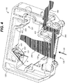
- FIG. 4 illustrates the prior exemplary electrical connector 110 including a sense pin in accordance with one segmented configuration.
- the sense pin 139 is shown hatched for clarity.
- the housing can be fabricated from a molding process, such as an injection molding process.
- the sense pin 139 is formed, then is retained in the mold (not shown) by grips (e.g., cylindrical pins) while the housing 120 is molded around the retained sense pin. Those grips leave at least one void 400 in housing 120.
- Function pins can also be similarly formed and molded-in, with or without retention grips. Function pins or the sense pin 139 can also be similarly retained during molding by grips holding parts of the pins outside the housing 120, e.g., segment 189.
- One or more first substrate(s) 351 are test strips used with a test meter, e.g., a glucose meter.
- the substrates 351 can be cycled through the connector 110, i.e., inserted and subsequently removed, four or more times per day.
- the connector 110 has a working life of at least five years, for a total of at least 7300 cycles.
- the sense pin 139 and the function pins 131, 132, 133, 134, 135 flex or bend.
- the pins 131, 132, 133, 134, 135, 139 experience strain, residual stresses in the materials of those pins can initiate cracks or accelerate their propagation, possibly causing fatigue failure of one or more of the pins. Accordingly, it is useful to fabricate the connector 110 in a manner that reduces residual stresses in the pins.
- diagonal segments in the pin 139 can be less resistant to the force applied by the plastic than are segments parallel or perpendicular to the defined direction 125.
- Such diagonal segments can be substantially parallel or perpendicular to the flow of plastic, instead of oblique thereto. Not using such diagonal segments can reduce twisting of the pin 139 during molding. Using the grips discussed above more firmly anchors the pin 139 in the mold, providing additional resistance to the force exerted by the molten plastic.
- the sense pin 139 can be designed with no segment (e.g., segments 288, 289, 189) extending other than substantially parallel or substantially perpendicular to the defined direction 125 of permitted insertion. This orientation can improve the stability and repeatability of forces on the sense pin 139 as a first substrate 351 ( FIG. 3 ) is inserted and removed from the connector 110, advantageously increasing the lifetime of the sense pin 139 and thus of connector 110.
- the connector 110 includes at least one first alignment feature 121, as discussed above.
- First alignment feature(s) 121, second alignment feature(s) 321, or both, can include at least one guiding surface 422 and at least one retaining surface 423, disposed along the defined direction 125 of permitted insertion.
- Guiding surface(s) 422 form respective acute angle(s) ⁇ (each surface 422 can have a different value of ⁇ ) with the defined direction 125 of permitted insertion.
- Retaining surface(s) 423 are substantially parallel to direction 125 of permitted insertion.
- Guiding surface(s) 422 lead a first substrate 351 ( FIG. 3 ) as a leading edge thereof approaches retaining surface(s) 423.
- FIG. 5 depicts a bottom view of test strip 550 partially inserted in the electrical connector 110.
- the test strip 550 includes a substrate 351, as shown in FIG. 3 .
- Retaining surfaces 523, 524 are as retaining surface 423 in FIG. 4 .
- second alignment feature 321 is spaced apart from the port 129 and first alignment feature 121.
- Alignment features 121, 321 are arranged to define a permitted angle ⁇ of first substrate 351 inserted into electrical connector 110 with respect to direction 125 of permitted insertion. If longitudinal axis 515 of test strip 550 is farther in magnitude from direction 125 than permitted angle ⁇ , test strip 550 will be blocked from full insertion into electrical connector 110 by alignment feature 121, 321, or both. In the example shown, ⁇ is at the permitted angle of (in this example) 1.93°. Test strip 550 can only be fully inserted into electrical connector 110 if longitudinal axis 515 is within 1.93° (in this example) of direction 125.
- test strip 550 is in contact with retaining surface 523 but not with retaining surface 524. If longitudinal axis 515 were 1.93° counterclockwise from direction 125, instead of 1.93° clockwise as shown here, end 551 would be in contact with retaining surface 524 but not with retaining surface 523.
- the spacing between retaining surfaces 523 and 524, width 309 ( FIG. 3 ) of port 129, and the relative positions of port 128 and alignment features 121, 321, are selected to provide a desired direction 125 and permitted angle ⁇ based on width 305 ( FIG. 3 ) of test strip 550 or its substrate 351.
- FIG. 6 shows components of a system for detecting an analyte in a bodily-fluid sample according to an example of the present invention.
- a controller 686 controls operation of the system.
- Controller 686 can include a microcontroller, microprocessor, field-programmable gate array (FPGA), programmable logic array or device (PLA or PLD), programmable array logic (PAL) device, digital signal processor (DSP), or other logic or processing component adapted to perform functions described herein, or more than one of any of those, in any combination.
- FPGA field-programmable gate array
- PLA or PLD programmable logic array or device
- PAL programmable array logic
- DSP digital signal processor
- Test strip 650 is similar to test strip 550 and includes a sample-receiving chamber 651 (dashed outline) and a plurality of conductive tracks 341, 342, 343, 344, 345 electrically discontinuous from each other.
- Each conductive track 341, 342, 343, 344, 345 is arranged at least partially on a first side 381 ( FIG. 3 ) of the test strip 650, and is and at least partially adjacent to the sample-receiving chamber 651. That is, each conductive track 341, 342, 343, 344, 345 is arranged so that the track's electrical properties can be influenced by a sample in the sample-receiving chamber 651, or so that electrical signals through the track can be applied to a sample in the sample-receiving chamber.
- each conductive track 341, 342, 343, 344, 345 can be adjacent to the sample-receiving chamber 651 on any side thereof, or more than one side thereof.
- the test strip 650 can also include other conductive tracks (not shown) that are not necessarily adjacent to the sample-receiving chamber 651.
- a fluid sample enters sample-receiving chamber 651 through port 70 (discussed below with reference to FIG. 12 ).
- Sample-receiving chamber 651 includes a sample channel extending from port 70, and an enzyme area (here, the wide rectangular portion overlapping the electrodes 671, 672, 673). An enzyme is deposited in the enzyme area; this is discussed below with reference to reagent layer 72 ( FIG. 12 ).
- Sense pin 139 ( FIG. 1 ) is mounted to the housing 120.
- the sense pin contact 149 (represented as a square) is adapted to electrically connect to at least one of the respective ones of the plurality of conductive tracks 341, 342, 343, 344, 345 of the test strip 650 inserted in the electrical connector 110.
- the sense pin contact 149 is arranged opposite the port 129 along the defined direction 125 of permitted insertion.
- the sense pin contact 149 does not have to be centered laterally (i.e., in a direction substantially perpendicular to the direction 125).
- each of the pin contacts can electrically connect to a respective, different conductive track 341, 342, 343, 344, 345, or more than one of the pin contacts can electrically connect to the same one of the conductive tracks 341, 342, 343, 344, 345.
- the function pins 131, 132, 133, 134, 135, 139 are not shown for clarity, but respective electrically-connected segments 181, 182, 183, 184, 185, 189 are shown, and connected to the contacts as indicated.
- the connection between the sense pin contact 149 and segment 189 is shown dashed only to visually differentiate that connection from other connections shown.
- the controller 686 communicates with some or all of the segments 181, 182, 183, 184, 185, 189, as represented graphically by the dotted line beneath each segment 181, 182, 183, 184, 185, 189 connecting the segment to the controller 686.
- a continuity sensor 690 is adapted to detect an electrical connection between the sense pin 139 and, respectively, each of the three or more function pins 131, 132, 133, 134, 135, and to provide to the controller 686 an indication of which function pin(s) 131, 132, 133, 134, 135 are electrically connected to the sense pin 139.
- the continuity sensor 690 is configured to detect an electrical connection between any of a selection of pin pairs.
- a continuity sensor 690 is electrically connected to segments 183 and 189 and can thus detect an electrical connection between a function pin 133 and the sense pin 139. In the example shown, this connection is made by an electrically-conductive strap 652 when test strip 650 is substantially fully inserted into the electrical connector 110.
- the continuity sensor 690 can wholly or partly be provided as a component of the controller 686, or can be a separate component communicating with the controller 686. Continuity sensor 690 can apply a test voltage or current, sense a test current, voltage, or magnetic field, or perform any suitable combination of those or other continuity-detection techniques.
- failure to detect continuity can be a result of non-insertion of a test strip 650, incomplete insertion of the test strip into the connector 110, insertion of a test strip that does not have strap 652 adapted to connect two contacts, or insertion of a test strip that does not have conductive tracks positioned to make electrical connection with the function pin and sense pin contacts 141, 142, 143, 144, 145, 149. Examples are discussed below.
- a storage unit 689 stores a plurality of selected continuity configurations and respective corresponding selections of two or more of the function pins. These are described below.
- a suitable storage unit 689 can include nonvolatile random-access memory (NVRAM), Flash memory, read-only memory (ROM), mask hardwiring, laser-trimmed resistors or traces on a silicon die, jumpers or resistors on a PCB or die, dual inline package (DIP) switches, PCB bridges or cuts, or other storage devices.
- the plurality of selected continuity configurations can be stored as data to be read by controller 686 or as code to be executed by controller 686.
- Storage unit 689 can include nonvolatile program storage for controller 686.
- the controller 686 is adapted to automatically respond to an indication from the continuity sensor 690 that an electrical connection has been detected between the sense pin 139 and at least one of the function pins 131, 132, 133, 134, 135. Controller 686 compares the provided indication of which of the function pins 131, 132, 133, 134, 135 is or are connected to sense pin 139 to each of the stored selected continuity configurations from storage unit 689. If the provided indication corresponds to one of the stored selected continuity configurations, controller 686 takes a measurement. As described herein , the terms "corresponds to" means that the provided indication and the selected continuity configuration represent the same conductive track on the test strip, whether or not the same identifier is used in the indication and the configuration. In an example shown here, a storage unit 689 can store a continuity configuration of "pin 133 connected" to the sense pin 139, and a corresponding selection of "pins 131, 132".
- the controller 686 takes a measurement by activating those function pin(s) indicated by the stored corresponding selection from the storage unit 689 (e.g., activate pins 131, 132). Activating those function pins results in applying a test electrical signal to or across the sample-receiving chamber 651 (note that the term "across" is conventional in the electrical arts and does not constrain the mechanical orientation of electrodes such as electrodes 671, 672). A resulting electrical signal is measured to detect the analyte in the sample-receiving chamber 651.
- the electrical signal is a voltage and the controller 686 is further adapted to measure a current between the two of the conductive tracks to detect the analyte.
- Detecting the analyte can include detecting whether or not an analyte is present in the sample-receiving chamber and, if so, detecting a property of that analyte.
- controller 686 receives from continuity sensor 690 an indication that a function pin 133 is electrically connected to the sense pin 139, controller 686 sees a match with one of the stored continuity configurations and retrieves the corresponding selection from storage unit 689. Since the corresponding selection includes function pins 131 and 132, controller 686 activates the function pins 131, 132 by supplying voltage or current to the segments 181, 182, respectively.
- the controller 686 can be further adapted to present an error indication if the provided indication does not correspond to any of the plurality of stored sleeted continuity configurations.
- the controller 686 can present the error via an output unit 669.
- Output unit 669 can include a device that produces a visual or audible indication to the user.
- the output unit 669 can include at least one light that blinks or is otherwise illuminated when the controller 686 presents the error; a bell, beeper or buzzer that sounds; or a horn that blows.
- an audio- or visual-reproduction system can be activated (e.g., a computer screen that displays a pop-up error dialog), or a network interface that transmits information about the error to a human-machine interface (HMI), server, terminal, smartphone, pager, or other computing or communications device.
- HMI human-machine interface
- Storage unit 689 stores a plurality of selected continuity configurations and respective corresponding selections of two or more of the function pins.
- a storage unit 689 can store: Continuity configuration: pin(s) connected to sense pin 139 Selection of function pins 131 132, 131 132 132, 131 133 132, 131 134 135, 134 135 135, 134
- the controller compares the provided indication to each of the stored selected continuity configurations. If the provided indication corresponds to one of the stored selected continuity configurations, the controller 686 activates the ones of the function pins indicated by the stored respective corresponding selection. An electrical signal is thus applied across the sample-receiving chamber 651 to detect the analyte in sample-receiving chamber 651, as described above.
- more than one set of function pins can be used simultaneously.
- the stored corresponding selection specifies that at least as many as two sets of at least two of the function pins each be activated.
- storage unit 689 stores: Continuity configuration: pin(s) connected to sense pin Selection of function pins: first set Selection of function pins: second set 131 132, 131 135, 134 132 132, 131 135, 134 133 132, 131 135, 134 134 134, 135 131, 132 135 134, 135 131, 132 135 134, 135 131, 132 135 134, 135 131, 132
- the bodily-fluid sample is whole blood.
- the controller can be adapted to apply the test electrical signal by applying a glucose-measurement signal across the function pins in the first set and, simultaneously or sequentially (in either order) applying a hematocrit-measurement signal across the function pins in the second set. This permits correcting for noise in glucose measurements that can be caused by varying hematocrit levels.
- the first set can include three function pins of the connector 110.
- the storage unit 689 stores the following, and the row marked (*) corresponds to the example shown in FIG. 6 :
- Continuity configuration pin(s) connected to sense pin Selection of function pins: first set Selection of function pins: second set 131 132, 133; 131 135, 134 132 132, 133; 131 135, 134 133 (*) 132, 133; 131 135, 134 134 134, 133; 135 131, 132 135 134, 133; 135 131, 132 135 134, 133; 135 131, 132
- the controller 686 applies the glucose measurement signal between a first of the three of the function pins and a second of the three of the function pins, e.g., in row (*), between pins 132 and 131.
- the controller 686 also applies the glucose measurement signal between a third of the three of the function pins and the second of the three of the function pins, e.g., between pins 133 and 131.
- pins 132 and 133 can be electrically connected, e.g., via conductive tracks 342, 343, respectively, to respective working electrodes 672, 673, both of which are operationally arranged adjacent to sample-receiving chamber 651 with respect to a common counter/reference electrode 671 electrically connected via conductive track 341 to pin 131.
- This provides a simple failsafe wherein measurements can be taken using only pin 132 if the electrode 673 or the conductive track 343 connected to pin 133 is inoperative (e.g., open due to mechanical damage), and vice versa. In various examples, this failsafe is used and hematocrit measurement is not used.
- Hematocrit can be measured with pins 134, 135 in the second set. These pins are connected via the conductive tracks 344, 345, respectively, to electrodes 674, 675, respectively.
- the electrodes 674, 675 are positioned between the port 70 and the electrode 671, which is the closest of electrodes 671, 672, 673 to port 70.
- the controller 686 applies a hematocrit-measurement signal or another sample-parameter measurement signal to the electrodes 674, 675.
- the controller 686 measures resulting electrical characteristics (e.g., voltage, current, waveform, or frequency) of signals on the electrodes 674, 675 and uses the measured characteristics to determine a parameter of the sample in the sample-receiving chamber 651. For example, the controller 686 can use a hematocrit measurement to set a glucose-assay delay time. Controller 686 then waits for the glucose-assay delay time to pass before applying the glucose measurement signal to the selected function pins.
- resulting electrical characteristics
- Measuring hematocrit can permit more accurate glucose readings in blood samples having a high hematocrit level or low hematocrit level.
- a hematocrit level represents a percentage of the volume occupied by red blood cells.
- a high hematocrit blood sample is more viscous (up to about 10 centipoise at 70% hematocrit) than a low hematocrit blood sample (about 3 centipoise at 20% hematocrit).
- a high hematocrit blood sample has a higher oxygen content than a low hematocrit blood because of the concomitant increase in hemoglobin, which is a carrier for oxygen.
- the hematocrit level can influence the viscosity and oxygen content of blood. Both viscosity and oxygen content can change the magnitude of the glucose current and in turn cause the glucose concentration measurement to be inaccurate. Measuring hematocrit permits correcting for those inaccuracies. Examples of hematocrit correction are given in US Patent Application Publication No. 2011/0005941 .
- An electrical connector 110 can further include two or more alignment features arranged, e.g., as shown in FIG. 3 .
- Respective contacts 141, 142, 143, 144, 145, 149 ( FIG. 3 ) of function pins 131, 132, 133, 134, 135 and sense pin 139 are between port 129 and each of the alignment features 121, 321 (both FIG. 3 ) in direction 125 of permitted insertion.
- sense pin 129 includes a plurality of electrically-connected segments, e.g., segments 288, 289, 189. At least one of the segments is mechanically mounted to housing 120. Each segment extends substantially parallel or substantially perpendicular to direction 125 of permitted insertion. In various instances, sense pin 129 does not include any segment extending other than substantially parallel or substantially perpendicular to direction 125 of permitted insertion.
- test strip and test meter combinations advantageously permit readily identifying analytical test strips as suitable or unsuitable for use by the test meter based on whether the signal processing module senses an appropriate electrical continuity or electrical discontinuity. Such identification advantageously permits the test meter to proceed with analyte determination only when appropriate, thus avoiding potentially improper, erroneous or inaccurate analyte determinations based on the use of unsuitable analytical test strips.
- commercial market “A” can be supplied with analytical test strips that have a first electrical configuration (e.g., strap 652 connecting pins 141, 149), while commercial market “B” can be supplied with analytical test strips that have a second, different electrical configuration (e.g., strap 652 connecting pins 145, 149).
- signal processing modules of test meters supplied to users in markets "A” and “B” would be programmed to identify analyte test strips with the appropriate electrical continuity or discontinuity as suitable for use and analyte test strips with inappropriate electrical continuity or discontinuity as unsuitable for use.
- a market B test meter would determine that the analytical test strip was unsuitable for use (because the indication would not match the stored continuity configuration) and, if desired, display an appropriate message to a user on a display module of the test meter.
- FIGS. 7-11 show layouts of conductive tracks on substrates 351.
- a plurality of conductive tracks 341, 342, 343, 344, 345 are shown, electrically connected to contacts 141, 142, 143, 144, 145 (represented graphically as circles), respectively.
- the sense pin contact 149 (represented graphically as a circle in FIG. 1 ) is also shown.
- FIG. 7 shows a strap 652 electrically connecting a function pin contact 143 to the sense pin contact 149.
- FIG. 8 shows strap 652 electrically connecting contact 141 to contact 149.
- FIG. 9 shows strap 652 electrically connecting contact 142 to contact 149.
- FIG. 10 shows strap 652 electrically connecting contact 144 to contact 149.
- FIG. 11 shows strap 652 electrically connecting contact 145 to contact 149.
- FIG. 12 is an exploded perspective view of an exemplary test strip. Further details are provided in US Patent Application Publication No. 2007/0074977 .
- the test strip 62 includes a first support layer 66, a spacer 60, and a second support layer 64.
- Support layers 66, 64 and spacer 60 can be electrically insulating, e.g., plastic.
- Support layers 66, 64 and spacer 60 can be sufficiently rigid to provide mechanical support to test strip 62, or can be layers coated over other sufficiently rigid structures.
- the test strip 62 includes a sample-receiving chamber 61 for receiving a sample, e.g., a bodily-fluid sample.
- Sample-receiving chamber 61 is formed by a cutout area 68 in the spacer 60.
- a sample, e.g., a bodily-fluid sample can be delivered through a port 70.
- Test strip 62 can have one or two ports 70, or more. One of the ports 70 can provide a sample inlet and the other can act as a vent.
- the sample-receiving chamber 61 can be adapted for analyzing small volume samples.
- a sample-receiving chamber 61 can have a volume ranging from about 0.1 microliters to about 5 microliters, or 0.2 to about 3 microliters, or about 0.3 microliters to about 1 microliter.
- electrodes of the test strip can be closely spaced.
- the height of spacer 60 can be in the range of about 1 micrometre to about 500 micrometres, or between about 10 micrometres and about 400 micrometres, or between about 40 micrometres and about 200 micrometres. More details of exemplary test strips are given in US Patent No. 8,163,162 .
- Electrodes can be arranged spaced apart in a facing or opposing faced arrangement, or in other coplanar or non-coplanar configurations.
- a reagent layer 72 can be disposed within the sample-receiving chamber 61 using a process such as slot coating, coating by dispensing liquid from the end of a tube, ink jetting, and screen printing. Such processes are described, for example, in U.S. Patent Nos. 6,749,887 ; 6,689,411 ; 6,676 , 995 ; and 6,830,934 .
- reagent layer 72 is deposited onto an electrode and includes at least a mediator and an enzyme.
- a mediator can be in either of two redox states which may be referred to as an oxidizable substance or a reducible substance.
- Suitable mediators include ferricyanide, ferrocene, ferrocene derivatives, osmium bipyridyl complexes, and quinone derivatives.
- suitable enzymes include glucose oxidase, glucose dehydrogenase (GDH) based on a pyrroloquinoline quinone co-factor, and GDH based on a nicotinamide adenine dinucleotide co-factor.
- GDH glucose dehydrogenase
- GDH glucose dehydrogenase
- a nicotinamide adenine dinucleotide co-factor One exemplary reagent formulation for reagent layer 72 is described in U.S. Application Ser. No. 10/242,951 , entitled, Method for Manufacturing a Sterilized and Calibrated Biosensor-Based Medical Device, published as U.S. Application Publication No. 2004/0120848 .
- Electrodes can be disposed over the face of first support layer 66 visible in FIG. 12 , and over the face of second support layer 64 not visible in FIG. 12 . Electrodes can be disposed on both faces of sample-receiving chamber 61, or around the edges thereof. Also disposed over support layer 66 or support layer 64 are one or more conductive tracks connected to the electrodes. In this example, conductive tracks 341, 342, 343, 344, 345 are disposed over support layer 66 and electrically connected to contacts 141, 142, 143, 144, 145 (represented graphically as black circles), respectively. A conductive track 341 is connected to the electrode 1201. Other electrodes are not shown, but each conductive track 341, 342, 343, 344, 345 can connect to zero or more electrodes.
- Spacer 60 can include electrically-conductive vias to provide electrical connections between conductive tracks on support layer 66 and conductive tracks on support layer 64. As discussed above with reference to FIG. 6 , contacts 141, 142, 143, 144, 145, 149 electrically connect with conductive tracks 341, 342, 343, 344, 345 to permit applying electrical signals to sample-receiving chamber 61 or a fluid or bodily-fluid sample therein.
- Test strip 62 can include a variety of electrical contact configurations for electrically connecting to a meter. For example, U.S. Patent No. 6,379,513 discloses electrochemical cell connection means.
- the electrodes can be thin films.
- electrodes include conductive material formed from materials such as gold, palladium, carbon, silver, platinum, tin oxide, iridium, indium, and combinations thereof (e.g., indium-doped tin oxide or "ITO").
- Electrodes can be formed by disposing a conductive material onto a support layer 66, 64 by a sputtering, electroless plating, or a screen printing process.
- sputtered gold electrode 1202 is disposed over side 1265 (the side not visible in FIG. 12 ) of support layer 64 and sputtered palladium electrode 1201 is disposed over side 1266 (the side visible in FIG.
- support layer 66 Suitable materials that can be employed as the insulating sheet include, for example, plastics (e.g. PET, PETG, polyimide, polycarbonate, polystyrene), silicon, ceramic, glass, and combinations thereof.
- plastics e.g. PET, PETG, polyimide, polycarbonate, polystyrene
- silicon e.g., silicon, ceramic, glass, and combinations thereof.
- support layers 64, 66 can be formed from 7 mil polyester substrate(s).
- support layer 66 includes a polyester base on which has been deposited, e.g., by sputtering, a Pd coating forming working electrode 1201.
- Dry reagent layer 72 includes buffer, mediator, and enzyme, as described herein.
- Spacer 60 is a double-sided adhesive having cutout area 68 that defines the electrochemical cell. The spacer can be less than about 200 ⁇ m thick.
- Support layer 64 includes a polyester base on which has been deposited, e.g., by sputtering, an Au coating forming reference electrode 1202.
- a glucose oxidase/ferricyanide system is used to determine glucose concentrations via the following reactions: Reaction 1: glucose + glucose oxidase ⁇ gluconic acid + reduced glucose oxidase Reaction 2: reduced glucose oxidase + 2 ferricyanide ⁇ glucose oxidase + 2 ferrocyanide.
- Ferricyanide [Fe(CN) 6 ] 3-
- Ferricyanide [Fe(CN) 6 ] 4-
- Ferrocyanide [Fe(CN) 6 ] 4-
- the concentration of ferrocyanide indicates the initial concentration of glucose.
- the total reaction is the sum of reactions 1 and 2.
- Reaction 3 glucose + 2 ferri cyanide ⁇ gluconic acid + 2 ferrocyanide
- Glucose refers specifically to ⁇ -D-glucose. Details of this system are described in PCT Application No. WO 97/18465 and US Patent No. 6,444,115 .
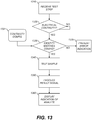
- FIG. 13 is an exemplary flowchart for determining an analyte in a bodily-fluid sample according to the present invention. Various combinations and orders of these steps can be used. Processing begins with step 1310.
- an analytical test strip is received using an electrical connector of a test meter.
- the analytical test strip includes a sample-receiving chamber adapted to receive the bodily-fluid sample, e.g., as shown in FIG. 12 .
- the receiving step is carried out according to this exemplary method such that at least three conductive tracks exposed on a first side of the analytical test strip make electrical contact with respective function pins of the electrical connector and at least one of the conductive tracks further makes electrical contact with a sense pin of the electrical connector, e.g., as shown in FIG. 6 .
- Step 1310 is followed by step 1320.
- a controller of the test meter is used to sense electrical continuities between the sense pin and, respectively, each of the at least three function pins.
- the controller can include or be electrically connected to a continuity sensor. The controller senses electrical continuity whether or not it relies on other components in doing so. When continuity is sensed, step 1320 is followed by step 1330. If no continuity is detected, the controller can wait for continuity, prompt a user to insert a strip, or signal an error.
- step 1330 when continuity is sensed, the controller compares an identity of the first one of the function pins to stored continuity-configuration information 1331.
- the identity of the first one of the function pins can be a pin number or position, or another identifying value correlated with those.
- step 1320 can include a continuity sensor providing a multi-bit digital value or bitmask to the controller, that value or bitmask indicating which of the function pins is electrically connected to the sense pin.
- step 1340 When the identity matches, step 1330 is followed by step 1340.
- step 1330 can be followed by step 1335.
- step 1335 the controller automatically presents an error indication.
- the error indicates that the identity of the first one of the function pins does not correspond to any of the plurality of stored values of continuity-configuration information.
- the error can be presented on a display, audio interface, network interface, or other device, e.g., as described above with reference to output unit 669 ( FIG. 6 ).
- step 1340 if the identity of the first one of the function pins corresponds to one of the plurality of stored values of continuity configuration information, the controller automatically applies a selected electrical signal to selected ones of the function pins indicated by the one of the plurality of stored values of continuity-configuration information and measures at least one result electrical signal. Step 1340 is followed by step 1350.
- Step 1330 includes the controller automatically comparing the identity of the first one of the function pins to each of a plurality of stored values of continuity-configuration information. If the identity matches one of the plurality, step 1340 includes the controller automatically applying a selected electrical signal to selected ones of the function pins indicated by the matching stored value of the continuity-configuration information. This permits using different configurations of test strips with one controller.
- step 1350 the controller automatically processes the result electrical signal to detect whether a bodily-fluid sample has been applied to the sample-receiving chamber and, if so, to determine the analyte in the applied bodily-fluid sample. Examples are discussed below. Step 1350 can be followed by step 1360.
- the analyte is glucose and the bodily-fluid sample is a whole blood sample.
- an indication of the determined analyte is presented on a display, e.g., by the controller automatically commanding the display.
- a display e.g., by the controller automatically commanding the display.
- the level of glucose in a blood sample measured in mg/dL or mmol/L, can be displayed as a number.
- An electrochemical (amperometric) method for measuring an analyte concentration in an aqueous sample involves placing the sample into a reaction zone (e.g., sample-receiving chamber 61, FIG. 12 ) in an electrochemical cell that has two electrodes (e.g., electrodes 1201, 1202, FIG. 12 ) having an impedance that is suitable for the amperometric measurement.
- the analyte is allowed to react directly with an electrode or with a redox reagent, as described above, to form an oxidizable (or reducible) substance in an amount that corresponds to the analyte concentration.
- the quantity of oxidizable (or reducible) substance is then determined electrochemically.
- the method accurately determines the point in time at which the sample is detected in the reaction zone. This permits an electrochemical waveform (e.g., voltage) to be applied immediately after the sample has been applied and accurately defines an incubation period or reaction time. In turn, this improves the accuracy and precision of the assay.
- electrochemical waveform e.g., voltage
- a small, constant current source can be applied across the electrode of an electrochemical diagnostic strip and a potential difference between the electrodes is monitored.
- a dry gap between electrodes 1201, 1202. Therefore, negligible current flows.
- the controller 686 FIG. 6
- the controller 686 can be configured to recognize the decrease in voltage as indicative of a sample and automatically stops applying a constant-current electrical signal to the selected ones of the function pins 131, 132, 133, 134, 135 ( FIG. 1 ).
- the controller can then apply a constant-voltage electrical signal to the selected ones of the function pins 131, 132, 133, 134, 135. While the constant voltage is applied, current or charge are measured as a function of time to permit the analyte concentration to be calculated.
- the current that is measured at a predetermined time after the constant voltage is applied is a measure of the analyte concentration, once the system has been calibrated using samples having known analyte concentrations.
- the duration of the predetermined time is not critical. It can be at least about 3 seconds when the fluid is blood and the analyte is glucose. That duration generally provides sufficient time to dissolve reagents and reduce an amount of mediator that is readily measurable. All things being equal, at high hematocrit, longer times are needed. The duration can be ⁇ 10s.
- the same predetermined time can be used for multiple successive measurements of respective samples. Further examples are given in US Patent No. 6,193,873 and US Patent Application Publication No. 2007/0074977 .
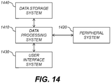
- FIG. 14 is a block diagram showing components of a data-processing system for analyzing data and performing other analyses described herein.
- the system includes a data processing system 1410, a peripheral system 1420, a user interface system 1430, and a data storage system 1440.
- the peripheral system 1420, the user interface system 1430 and the data storage system 1440 are communicatively connected to the data processing system 1410.
- the controller 186 and receiver 130 can each include one or more of systems 1410, 1420, 1430, 1440.
- the data processing system 1410 includes one or more data processing devices that implement the processes of the various examples described herein.
- the phrases "data processing device” or “data processor” are intended to include any data processing device, such as a central processing unit (“CPU"), a desktop computer, a laptop computer, a mainframe computer, a personal digital assistant, a BlackberryTM, a digital camera, cellular phone, or any other device for processing data, managing data, or handling data, whether implemented with electrical, magnetic, optical, biological components, or otherwise.
- CPU central processing unit
- BlackberryTM a digital camera
- cellular phone or any other device for processing data, managing data, or handling data, whether implemented with electrical, magnetic, optical, biological components, or otherwise.
- the data storage system 1440 includes one or more processor-accessible memories configured to store information, including the information needed to execute the processes of the various examples described herein.
- the data storage system 1440 can be a distributed processor-accessible memory system including multiple processor-accessible memories communicatively connected to the data processing system 1410 via a plurality of computers or devices.
- the data storage system 1440 need not be a distributed processor-accessible memory system and, consequently, can include one or more processor-accessible memories located within a single data processor or device.
- Data storage system 1440 in controller 686 includes code or other commands to cause signal processing module 386 to carry out a suitable algorithm that determines an analyte based on the electrochemical response of analytical test strip 650 ( FIG. 6 ).
- the algorithm can accommodate the electrochemical response of various electrodes (e.g., electrode 1201, FIG. 12 ) within electrochemical-based analytical test strip 650.
- processor-accessible memory is intended to include any processor-accessible data storage device, whether volatile or nonvolatile, electronic, magnetic, optical, or otherwise, including but not limited to, registers, floppy disks, hard disks, Compact Discs, DVDs, flash memories, ROMs, and RAMs.
- the phrase "communicatively connected” is intended to include any type of connection, whether wired or wireless, between devices, data processors, or programs in which data can be communicated.
- the phrase "communicatively connected” is intended to include a connection between devices or programs within a single data processor, a connection between devices or programs located in different data processors, and a connection between devices not located in data processors.
- the data storage system 1440 is shown separately from the data processing system 1410, one skilled in the art will appreciate that the data storage system 1440 can be stored completely or partially within the data processing system 1410.
- the peripheral system 1420 and the user interface system 1430 are shown separately from the data processing system 1410, one skilled in the art will appreciate that one or both of such systems can be stored completely or partially within the data processing system 1410.
- the peripheral system 1420 can include one or more devices configured to provide digital content records to the data processing system 1410.
- the peripheral system 1420 can include digital still cameras, digital video cameras, cellular phones, or other data processors.
- the data processing system 1410 upon receipt of digital content records from a device in the peripheral system 1420, can store such digital content records in the data storage system 1440.
- the user interface system 1430 can include a mouse, a keyboard, another computer, or any device or combination of devices from which data is input to the data processing system 1410.
- the peripheral system 1420 is shown separately from the user interface system 1430, the peripheral system 1420 can be included as part of the user interface system 1430.
- the user interface system 1430 also can include a display device, a processor-accessible memory, or any device or combination of devices to which data is output by the data processing system 1410.
- a display device e.g., a liquid crystal display
- a processor-accessible memory e.g., a liquid crystal display
- the user interface system 1430 includes a processor-accessible memory, such memory can be part of the data storage system 1440 even though the user interface system 1430 and the data storage system 1440 are shown separately in FIG. 14 .
- the present invention can be embodied as a system or a method. Accordingly, embodiments may take the form of entirely hardware, or a combination of software and hardware. These forms and instances can all generally be referred to herein as a "service,” “circuit,” “circuitry,” “module,” or “system.”
- a computer program product embodied in one or more computer readable medium(s) having computer readable program code embodied thereon.
- a computer program product can include one or more storage media, for example; magnetic storage media such as magnetic disk (such as a floppy disk) or magnetic tape; optical storage media such as optical disk, optical tape, or machine readable bar code; solid-state electronic storage devices such as random access memory (RAM), or read-only memory (ROM); or any other physical device or media employed to store a computer program having instructions for controlling one or more computers to practice various examples.
- Computer-readable storage media include a portable computer diskette, a hard disk, a random access memory (RAM), a read-only memory (ROM), an erasable programmable read-only memory (EPROM or Flash memory), an optical fiber, a portable compact disc read-only memory (CD-ROM), an optical storage device, a magnetic storage device, or any suitable combination of the foregoing.
- a computer readable storage medium may be any tangible medium that can contain, or store a program for use by or in connection with an instruction execution system, apparatus, or device.
- Program code and/or executable instructions embodied on a computer readable medium may be transmitted using any appropriate medium, including but not limited to wireless, wireline, optical fiber cable, RF, or any suitable combination of appropriate media.
- Computer program code for carrying out operations for various examples can execute entirely on the user's computer (device), partly on the user's computer, as a stand-alone software package, partly on the user's computer and partly on a remote computer or entirely on the remote computer or server.
- the remote computer may be connected to the user's computer through any type of network, including a local area network (LAN) or a wide area network (WAN), or the connection may be made to an external computer (for example, through the Internet using an Internet Service Provider).
- LAN local area network
- WAN wide area network
- Internet Service Provider for example, AT&T, MCI, Sprint, EarthLink, MSN, GTE, etc.
- Computer program instructions can be stored in a computer readable medium that can direct a computer, other programmable data processing apparatus, or other devices to function in a particular manner.
- the computer program instructions may also be loaded onto a computer, other programmable data processing apparatus, or other devices to cause a series of operational steps to be performed on the computer, other programmable apparatus or other devices to produce a computer implemented process such that the instructions which execute on the computer or other programmable apparatus provide processes for implementing the functions/acts specified herein.
Landscapes
- Health & Medical Sciences (AREA)
- Engineering & Computer Science (AREA)
- Life Sciences & Earth Sciences (AREA)
- Biomedical Technology (AREA)
- Physics & Mathematics (AREA)
- Chemical & Material Sciences (AREA)
- Biochemistry (AREA)
- General Health & Medical Sciences (AREA)
- Molecular Biology (AREA)
- Urology & Nephrology (AREA)
- Optics & Photonics (AREA)
- Food Science & Technology (AREA)
- Medicinal Chemistry (AREA)
- Analytical Chemistry (AREA)
- Hematology (AREA)
- General Physics & Mathematics (AREA)
- Biophysics (AREA)
- Immunology (AREA)
- Pathology (AREA)
- Microelectronics & Electronic Packaging (AREA)
- Investigating Or Analyzing Materials By The Use Of Electric Means (AREA)
- Investigating Or Analysing Biological Materials (AREA)
- Measurement Of The Respiration, Hearing Ability, Form, And Blood Characteristics Of Living Organisms (AREA)
Claims (11)
- Système destiné à détecter un analyte dans un échantillon de fluide corporel, ledit système comprenant :a) un contrôleur (686) ;b) une bandelette réactive (62) ayant une chambre de réception d'échantillon (61) et une pluralité de pistes conductrices (341, 342, 343, 344, 345) électriquement discontinues les unes des autres, chaque piste conductrice (341, 342, 343, 344, 345) étant disposée au moins partiellement sur un premier côté de ladite bandelette réactive (62) et au moins partiellement adjacente à la chambre de réception d'échantillon (61) ;c) un connecteur électrique (110) comprenant :i) un boîtier (120) avec un orifice (129) adapté pour recevoir la bandelette réactive (62) insérée dans une direction d'insertion autorisée (125) ;ii) au moins trois broches de fonction (131, 132, 133, 134, 135) montées sur le boîtier (120), chaque dite broche de fonction (131, 132, 133, 134, 135) ayant un contact respectif (141, 142, 143, 144, 145) agencé pour se raccorder électriquement à une piste respective de la pluralité de pistes conductrices (341, 342, 343, 344, 345) de la bandelette réactive (62) insérée dans le connecteur électrique (110) ; etiii) une broche de détection (139) montée sur le boîtier (120) et ayant un contact (149) adapté pour se raccorder électriquement à une des pistes respectives de la pluralité de pistes conductrices (341, 342, 343, 344, 345) de la bandelette réactive (62) insérée dans le connecteur électrique (110), le contact (149) de ladite broche de détection (139) étant disposé à l'opposé de l'orifice (129) le long de la direction d'insertion autorisée (125) ;d) un capteur de continuité (690) adapté pour détecter des continuités électriques entre la broche de détection (139) et, respectivement, chacune des au moins trois broches de fonction (131, 132, 133, 134, 135), les continuités électriques fournissant une indication sur celle(s) des au moins trois broches de fonction (131, 132, 133, 134, 135) qui est/sont raccordée(s) électriquement à la broche de détection (139) ; ete) une unité de stockage (689), l'unité de stockage (689) stockant une pluralité de configurations de continuité sélectionnées et des sélections correspondantes respectives d'au moins deux des broches de fonction (131, 132, 133, 134, 135),
la sélection d'au moins deux broches de fonction (131, 132, 133, 134, 135) correspondant à une première configuration de continuité sélectionnée parmi la pluralité de configurations de continuité sélectionnées différant de la sélection d'au moins deux broches de fonction (131, 132, 133, 134, 135) correspondant à une deuxième configuration de continuité sélectionnée parmi la pluralité de configurations de continuité sélectionnées ;
dans lequel le contrôleur (686) est adapté pour, automatiquement :i) en réponse au capteur de continuité (690), comparer l'indication fournie à chacune des configurations de continuité sélectionnées stockées ; etii) si l'indication fournie correspond à une des configurations de continuité sélectionnées stockées, activer celles des broches de fonction (131, 132, 133, 134, 135) indiquées par la sélection correspondante respective stockée pour appliquer un signal électrique à travers la chambre de réception d'échantillon (61), et mesurer un signal électrique résultant pour détecter l'analyte dans la chambre de réception d'échantillon (61) . - Système selon la revendication 1, dans lequel le contrôleur (686) est également adapté pour présenter une indication d'erreur si l'indication fournie ne correspond à aucune de la pluralité de configurations de continuité sélectionnées stockées.
- Système selon la revendication 1, dans lequel :a) l'échantillon de fluide corporel est du sang total ;b) au moins une des sélections correspondantes stockées spécifie que deux ensembles d'au moins deux des broches de fonction (131, 132, 133, 134, 135) doivent être chacun activés ; etc) le contrôleur (686) est adapté pour appliquer le signal électrique en appliquant un signal de mesure de glucose à travers les broches de fonction (131, 132, 133, 134, 135) dans le premier ensemble et en appliquant un signal de mesure d'hématocrite à travers les broches de fonction (131, 132, 133, 134, 135) dans le deuxième ensemble.
- Système selon la revendication 3, dans lequel le premier ensemble comporte trois des broches de fonction (131, 132, 133, 134, 135) et le contrôleur (686) applique le signal de mesure de glucose entre une première des trois broches de fonction données (131, 132, 133, 134, 135) et une deuxième des trois broches de fonction données (131, 132, 133, 134, 135), mais aussi entre une troisième des trois broches de fonction données (131, 132, 133, 134, 135) et la deuxième des trois broches de fonction données (131, 132, 133, 134, 135) .
- Système selon la revendication 1, dans lequel le connecteur électrique (110) comporte en outre deux éléments d'alignement (121, 321) disposés de telle sorte que les contacts respectifs (141, 142, 143, 144, 145, 149) des broches de fonction (131, 132, 133, 134, 135) et de la broche de détection (139) se situent entre l'orifice (129) et chacun des éléments d'alignement (121, 321) dans la direction d'insertion autorisée (125).
- Système selon la revendication 1, dans lequel la broche de détection (139) comporte une pluralité de segments raccordés électriquement (189, 288, 289), au moins un desdits segments raccordés électriquement étant monté mécaniquement sur le boîtier, chaque dit segment raccordé électriquement (189, 288, 289) s'étendant de façon sensiblement parallèle ou sensiblement perpendiculaire à la direction d'insertion autorisée (125).
- Système selon la revendication 1, dans lequel la broche de détection (139) ne comporte aucun segment s'étendant d'une autre façon que sensiblement parallèle ou sensiblement perpendiculaire à la direction d'insertion autorisée (125).
- Procédé de détermination d'un analyte dans un échantillon de fluide corporel, le procédé comprenant :la réception (1310) d'une bandelette réactive (62) au moyen d'un connecteur électrique (110) d'un appareil de mesure de telle sorte qu'au moins trois pistes conductrices (341, 342, 343, 344, 345) exposées sur un premier côté de la bandelette réactive (62) fassent contact électrique avec trois broches de fonction respectives (131, 132, 133, 134, 135) du connecteur électrique (110) et au moins une des pistes conductrices (341, 342, 343, 344, 345) fasse également contact électrique avec une broche de détection (139) du connecteur électrique (110), la bandelette réactive (62) comportant une chambre de réception d'échantillon (61) adaptée pour recevoir l'échantillon de fluide corporel ;la détection (1320), au moyen d'un contrôleur (686) de l'appareil de mesure, de continuités électriques entre la broche de détection (139) et, respectivement, chacune des trois broches de fonction (131, 132, 133, 134, 135) ;quand une continuité est détectée, la comparaison (1330), par le contrôleur (686), d'une identité d'une première des trois broches de fonction (131, 132, 133, 134, 135) à des informations de configuration de continuité stockées ;si l'identité de la première des trois broches de fonction (131, 132, 133, 134, 135) correspond aux informations de configuration de continuité stockées, l'application automatique (1340), par le contrôleur (686), d'un signal électrique sélectionné à des broches sélectionnées parmi les trois broches de fonction (131, 132, 133, 134, 135) indiquées par les informations de configuration de continuité stockées et la mesure d'un signal électrique résultant ; etle traitement automatique (1350), par le contrôleur (686), du signal électrique résultant pour détecter si un échantillon de fluide corporel a été appliqué à la chambre de réception d'échantillon (61) et, le cas échéant, pour déterminer l'analyte dans l'échantillon de fluide corporel appliqué ;dans lequel l'étape de comparaison (1330) comporte la comparaison automatique, par le contrôleur (686), de l'identité de la première des trois broches de fonction (131, 132, 133, 134, 135) à chacune d'une pluralité de valeurs stockées d'information de configuration de continuité, une première valeur stockée d'information de configuration de continuité dans la pluralité de valeurs stockées d'information de configuration de continuité différant d'une deuxième valeur stockée d'information de configuration de continuité dans la pluralité de valeurs stockées d'information de configuration de continuité, et si l'identité correspond à une de la pluralité de valeurs stockées d'information de configuration de continuité, l'application automatique, par le contrôleur (686), d'un signal électrique sélectionné à des broches sélectionnées parmi les trois broches de fonction (131, 132, 133, 134, 135) indiquées par la valeur stockée correspondante d'information de configuration de continuité.
- Procédé selon la revendication 8, dans lequel l'analyte est le glucose et l'échantillon de fluide corporel est un échantillon de sang total.
- Procédé selon la revendication 8, comportant en outre la présentation (1360) d'une indication de l'analyte déterminé sur un écran.
- Procédé selon la revendication 8, comportant en outre la présentation automatique (1335), par le contrôleur (686), d'une indication d'erreur si l'identité de la première des trois broches de fonction (131, 132, 133, 134, 135) ne correspond à aucune de la pluralité de valeurs stockées d'information de configuration de continuité.
Priority Applications (1)
| Application Number | Priority Date | Filing Date | Title |
|---|---|---|---|
| EP19204116.8A EP3620791A1 (fr) | 2012-12-20 | 2013-12-19 | Connecteur électrique pour substrat disposant de pistes conductrices |
Applications Claiming Priority (2)
| Application Number | Priority Date | Filing Date | Title |
|---|---|---|---|
| US13/722,983 US8926369B2 (en) | 2012-12-20 | 2012-12-20 | Electrical connector for substrate having conductive tracks |
| PCT/GB2013/053354 WO2014096826A1 (fr) | 2012-12-20 | 2013-12-19 | Connecteur électrique pour substrat présentant des pistes conductrices |
Related Child Applications (1)
| Application Number | Title | Priority Date | Filing Date |
|---|---|---|---|
| EP19204116.8A Division EP3620791A1 (fr) | 2012-12-20 | 2013-12-19 | Connecteur électrique pour substrat disposant de pistes conductrices |
Publications (2)
| Publication Number | Publication Date |
|---|---|
| EP2936148A1 EP2936148A1 (fr) | 2015-10-28 |
| EP2936148B1 true EP2936148B1 (fr) | 2019-11-20 |
Family
ID=49917183
Family Applications (2)
| Application Number | Title | Priority Date | Filing Date |
|---|---|---|---|
| EP19204116.8A Withdrawn EP3620791A1 (fr) | 2012-12-20 | 2013-12-19 | Connecteur électrique pour substrat disposant de pistes conductrices |
| EP13815806.8A Not-in-force EP2936148B1 (fr) | 2012-12-20 | 2013-12-19 | Système et procédé pour détecter un analyte dans un échantillon corporel fluidique |
Family Applications Before (1)
| Application Number | Title | Priority Date | Filing Date |
|---|---|---|---|
| EP19204116.8A Withdrawn EP3620791A1 (fr) | 2012-12-20 | 2013-12-19 | Connecteur électrique pour substrat disposant de pistes conductrices |
Country Status (12)
| Country | Link |
|---|---|
| US (1) | US8926369B2 (fr) |
| EP (2) | EP3620791A1 (fr) |
| JP (1) | JP2016502100A (fr) |
| KR (1) | KR20150099794A (fr) |
| CN (1) | CN105008921B (fr) |
| AU (1) | AU2013366021B2 (fr) |
| BR (1) | BR112015014892A2 (fr) |
| CA (2) | CA2895641C (fr) |
| ES (1) | ES2768267T3 (fr) |
| RU (1) | RU2015129544A (fr) |
| TW (1) | TW201448360A (fr) |
| WO (1) | WO2014096826A1 (fr) |
Families Citing this family (13)
| Publication number | Priority date | Publication date | Assignee | Title |
|---|---|---|---|---|
| KR102240512B1 (ko) * | 2014-07-31 | 2021-04-16 | 삼성전자주식회사 | 혈당 측정 장치, 혈당 측정 방법 및 혈당 측정 모듈을 포함하는 전자 장치 |
| US10114031B2 (en) | 2014-09-26 | 2018-10-30 | Abbott Point Of Care Inc. | Single channel cartridge device for coagulation assays in fluid samples |
| CN107107057B (zh) * | 2014-09-26 | 2020-12-15 | 雅培医护站股份有限公司 | 用于流体样本中的凝结测定的盒设备识别 |
| EP3198281B1 (fr) | 2014-09-26 | 2023-01-25 | Abbott Point Of Care, Inc. | Formulations d'acide ellagique pour une utilisation dans des tests de coagulation |
| WO2016049533A1 (fr) | 2014-09-26 | 2016-03-31 | Abbott Point Of Care Inc. | Dispositif cartouche avec jonctions fluidiques pour mesures de coagulation dans des échantillons de fluide |
| WO2016049515A1 (fr) * | 2014-09-26 | 2016-03-31 | Abbott Point Of Care Inc. | Dispositif microfabriqué avec des capteurs de microenvironnement pour analyser la coagulation dans des échantillons fluides |
| TWI652871B (zh) * | 2016-07-07 | 2019-03-01 | 莫仕有限公司 | 微型配電盒及其製造方法 |
| US20180059092A1 (en) * | 2016-08-25 | 2018-03-01 | Cilag Gmbh International | Hand-held test meter with smooth dimpled electrical contacts, contact stopper ribs, and metal shield plate |
| GB2553355A (en) * | 2016-09-05 | 2018-03-07 | Continental Automotive Gmbh | Connection device for providing a mechanical and electrical connection of at least one sensor element to an electronic circuit, and cable endpiece |
| CN110231537B (zh) * | 2019-06-29 | 2021-10-29 | 潍柴动力股份有限公司 | 一种ecu针脚错误配置的检测方法及装置 |
| KR20230062816A (ko) * | 2020-09-07 | 2023-05-09 | 어센시아 다이어비티즈 케어 홀딩스 아게 | 연속 피분석물 모니터링 디바이스의 베이스 유닛에 전자 유닛의 결합을 가능하게 하는 방법 및 장치 |
| TWI814562B (zh) * | 2022-08-31 | 2023-09-01 | 超極生技股份有限公司 | 用於量測氣體酸鹼度的電化學試片 |
| CN116169532B (zh) * | 2023-02-22 | 2026-03-03 | 中航光电科技股份有限公司 | 一种弹载用射频刚柔印制板组件 |
Family Cites Families (54)
| Publication number | Priority date | Publication date | Assignee | Title |
|---|---|---|---|---|
| US995A (en) | 1838-11-03 | Lansing b | ||
| US6676A (en) | 1849-08-28 | Gold-washer | ||
| AUPN661995A0 (en) | 1995-11-16 | 1995-12-07 | Memtec America Corporation | Electrochemical cell 2 |
| AUPO581397A0 (en) | 1997-03-21 | 1997-04-17 | Memtec America Corporation | Sensor connection means |
| US6039599A (en) * | 1997-06-30 | 2000-03-21 | The Whitaker Corporation | Switch for a card reader assembly |
| JPH1140270A (ja) * | 1997-07-11 | 1999-02-12 | Amp Japan Ltd | カード用コネクタ |
| US6830934B1 (en) | 1999-06-15 | 2004-12-14 | Lifescan, Inc. | Microdroplet dispensing for a medical diagnostic device |
| US6193873B1 (en) | 1999-06-15 | 2001-02-27 | Lifescan, Inc. | Sample detection to initiate timing of an electrochemical assay |
| FR2796763B1 (fr) * | 1999-07-23 | 2002-02-01 | Itt Mfg Enterprises Inc | Connecteur electrique pour carte a circuit(s) integre(s) comportant un commutateur de verrou du couvercle porte carte |
| US20060091006A1 (en) | 1999-11-04 | 2006-05-04 | Yi Wang | Analyte sensor with insertion monitor, and methods |
| US6616819B1 (en) | 1999-11-04 | 2003-09-09 | Therasense, Inc. | Small volume in vitro analyte sensor and methods |
| JP3429732B2 (ja) * | 2000-05-22 | 2003-07-22 | 大宏電機株式会社 | 電気コネクタ及びその製造方法 |
| US6444115B1 (en) | 2000-07-14 | 2002-09-03 | Lifescan, Inc. | Electrochemical method for measuring chemical reaction rates |
| JP4264478B2 (ja) * | 2001-09-28 | 2009-05-20 | アークレイ株式会社 | 測定用具および濃度測定装置 |
| JP2003146469A (ja) * | 2001-11-05 | 2003-05-21 | Kanegafuchi Chem Ind Co Ltd | 媒体搬送ベルト及びその製造方法 |
| US6749887B1 (en) | 2001-11-28 | 2004-06-15 | Lifescan, Inc. | Solution drying system |
| US6689411B2 (en) | 2001-11-28 | 2004-02-10 | Lifescan, Inc. | Solution striping system |
| US6743635B2 (en) | 2002-04-25 | 2004-06-01 | Home Diagnostics, Inc. | System and methods for blood glucose sensing |
| US20080112852A1 (en) * | 2002-04-25 | 2008-05-15 | Neel Gary T | Test Strips and System for Measuring Analyte Levels in a Fluid Sample |
| US6946299B2 (en) * | 2002-04-25 | 2005-09-20 | Home Diagnostics, Inc. | Systems and methods for blood glucose sensing |
| DE60324738D1 (de) | 2002-07-18 | 2009-01-02 | Panasonic Corp | Messvorrichtung mit einem Biosensor |
| US20040120848A1 (en) | 2002-12-20 | 2004-06-24 | Maria Teodorczyk | Method for manufacturing a sterilized and calibrated biosensor-based medical device |
| KR100502713B1 (ko) | 2003-05-29 | 2005-07-20 | 주식회사 헬스피아 | 자가 진단용 배터리 팩과 자가 진단 시스템 |
| US7645421B2 (en) * | 2003-06-20 | 2010-01-12 | Roche Diagnostics Operations, Inc. | System and method for coding information on a biosensor test strip |
| CN2682649Y (zh) * | 2003-12-25 | 2005-03-02 | 富士康(昆山)电脑接插件有限公司 | 电子卡连接器 |
| CN2736962Y (zh) * | 2004-09-21 | 2005-10-26 | 富士康(昆山)电脑接插件有限公司 | 电子卡连接器 |
| TWM279070U (en) * | 2005-04-01 | 2005-10-21 | Hon Hai Prec Ind Co Ltd | Electrical card connector |
| JP4678333B2 (ja) * | 2005-09-29 | 2011-04-27 | 住友電装株式会社 | レバー式コネクタ |
| US7749371B2 (en) | 2005-09-30 | 2010-07-06 | Lifescan, Inc. | Method and apparatus for rapid electrochemical analysis |
| US7381096B2 (en) * | 2005-10-28 | 2008-06-03 | Hewlett-Packard Development Company, L.P. | Media power protection system and method |
| CN2847573Y (zh) * | 2005-11-22 | 2006-12-13 | 上海莫仕连接器有限公司 | 电子卡连接器 |
| US7488216B2 (en) * | 2005-12-02 | 2009-02-10 | Biomedix Taiwan Co., Ltd. | Connector to receive blood test chips for use with a blood-substance measuring device |
| US8163162B2 (en) | 2006-03-31 | 2012-04-24 | Lifescan, Inc. | Methods and apparatus for analyzing a sample in the presence of interferents |
| EP2957908A1 (fr) | 2006-10-05 | 2015-12-23 | Lifescan Scotland Limited | Procédés de détermination d'une concentration d'analyte à l'aide d'algorithmes de traitement de signal |
| TWM325636U (en) * | 2006-11-30 | 2008-01-11 | Tai Sol Electronics Co Ltd | Electronic card connector having detection function of card-insertion |
| TWM326718U (en) * | 2007-06-04 | 2008-02-01 | Hon Hai Prec Ind Co Ltd | Electrical card connector |
| US7875461B2 (en) | 2007-07-24 | 2011-01-25 | Lifescan Scotland Limited | Test strip and connector |
| TW200914826A (en) | 2007-09-21 | 2009-04-01 | Apex Biotechnology Corp | Electrochemical quantitative analysis system and method for the same |
| US20090095623A1 (en) | 2007-10-10 | 2009-04-16 | Agamatrix, Inc. | Identification Method for Electrochemical Test Strips |
| JP2009176510A (ja) * | 2008-01-23 | 2009-08-06 | Honda Tsushin Kogyo Co Ltd | メモリーカード用コネクタ |
| JP4964800B2 (ja) * | 2008-02-14 | 2012-07-04 | モレックス インコーポレイテド | カード用コネクタ |
| US7896703B2 (en) | 2008-07-17 | 2011-03-01 | Abbott Diabetes Care Inc. | Strip connectors for measurement devices |
| WO2010042586A1 (fr) * | 2008-10-07 | 2010-04-15 | Molex Incorporated | Capuchon de terminaison utilisé dans un système de gestion de réseau câblé |
| MY155070A (en) * | 2009-01-23 | 2015-08-28 | Molex Inc | Socket connector having detecting switch |
| WO2010091793A2 (fr) | 2009-01-30 | 2010-08-19 | Pelikan Technologies Gmbh & Co. Kg | Dispositif de mesure d'analytes avec un arrière-plan de codage sur bandelette |
| CN101807753B (zh) * | 2009-02-17 | 2012-12-19 | 富士康(昆山)电脑接插件有限公司 | 卡连接器 |
| US7775826B1 (en) * | 2009-06-12 | 2010-08-17 | Cheng Uei Precision Industry Co., Ltd. | Card connector |
| US20110057671A1 (en) | 2009-09-04 | 2011-03-10 | Lifescan Scotland, Ltd. | Methods, system and device to identify a type of test strip |
| US8608920B2 (en) | 2009-12-14 | 2013-12-17 | Taidoc Technology Corporation | Electrochemical biosensor strip and method for identifying a corresponding biosensing device by said strip |
| US8828330B2 (en) | 2010-01-28 | 2014-09-09 | Abbott Diabetes Care Inc. | Universal test strip port |
| JP5576688B2 (ja) * | 2010-03-16 | 2014-08-20 | 日本光電工業株式会社 | コネクタ、カードエッジコネクタ及びそれを使用したセンサ |
| JP5585156B2 (ja) * | 2010-03-26 | 2014-09-10 | ミツミ電機株式会社 | 薄型コネクタ |
| US7896670B1 (en) * | 2010-04-30 | 2011-03-01 | Cheng Uei Precision Industry Co., Ltd. | Card connector |
| MX367439B (es) * | 2010-06-07 | 2019-08-22 | Ascensia Diabetes Care Holdings Ag | Sistema de gestion de llenado insuficiente para un biosensor. |
-
2012
- 2012-12-20 US US13/722,983 patent/US8926369B2/en active Active
-
2013
- 2013-12-18 TW TW102146816A patent/TW201448360A/zh unknown
- 2013-12-19 AU AU2013366021A patent/AU2013366021B2/en not_active Ceased
- 2013-12-19 BR BR112015014892A patent/BR112015014892A2/pt not_active Application Discontinuation
- 2013-12-19 WO PCT/GB2013/053354 patent/WO2014096826A1/fr not_active Ceased
- 2013-12-19 EP EP19204116.8A patent/EP3620791A1/fr not_active Withdrawn
- 2013-12-19 CN CN201380073486.5A patent/CN105008921B/zh not_active Expired - Fee Related
- 2013-12-19 KR KR1020157019409A patent/KR20150099794A/ko not_active Ceased
- 2013-12-19 ES ES13815806T patent/ES2768267T3/es active Active
- 2013-12-19 EP EP13815806.8A patent/EP2936148B1/fr not_active Not-in-force
- 2013-12-19 CA CA2895641A patent/CA2895641C/fr active Active
- 2013-12-19 JP JP2015548756A patent/JP2016502100A/ja active Pending
- 2013-12-19 RU RU2015129544A patent/RU2015129544A/ru not_active Application Discontinuation
- 2013-12-19 CA CA3126526A patent/CA3126526C/fr active Active
Non-Patent Citations (1)
| Title |
|---|
| None * |
Also Published As
| Publication number | Publication date |
|---|---|
| HK1215071A1 (en) | 2016-08-12 |
| TW201448360A (zh) | 2014-12-16 |
| EP3620791A1 (fr) | 2020-03-11 |
| CN105008921A (zh) | 2015-10-28 |
| CA3126526A1 (fr) | 2014-06-26 |
| JP2016502100A (ja) | 2016-01-21 |
| BR112015014892A2 (pt) | 2017-07-11 |
| RU2015129544A (ru) | 2017-01-25 |
| US8926369B2 (en) | 2015-01-06 |
| KR20150099794A (ko) | 2015-09-01 |
| AU2013366021B2 (en) | 2019-01-03 |
| CA2895641C (fr) | 2022-01-04 |
| AU2013366021A1 (en) | 2015-07-23 |
| ES2768267T3 (es) | 2020-06-22 |
| CA3126526C (fr) | 2023-07-18 |
| EP2936148A1 (fr) | 2015-10-28 |
| WO2014096826A1 (fr) | 2014-06-26 |
| CN105008921B (zh) | 2018-12-07 |
| US20140179151A1 (en) | 2014-06-26 |
| CA2895641A1 (fr) | 2014-06-26 |
Similar Documents
| Publication | Publication Date | Title |
|---|---|---|
| EP2936148B1 (fr) | Système et procédé pour détecter un analyte dans un échantillon corporel fluidique | |
| US9395319B2 (en) | Analytical test meter | |
| US20150241378A1 (en) | Electrochemical-based analytical test strip with bare interferent electrodes | |
| CN216978925U (zh) | 一种检测用的生物传感器 | |
| US9541520B2 (en) | Analytical test strip | |
| TW201534915A (zh) | 雙腔室分析測試條 | |
| EP2990784B1 (fr) | Procédé de mesure d'échantillon liquide | |
| US20110284393A1 (en) | Analytical test strip with an electrode having electrochemically active and inert areas of a predetermined size and distribution | |
| US20120312699A1 (en) | Differentiable analytical test strip and test meter combination | |
| EP2297574B1 (fr) | Biocapteur | |
| HK1215071B (en) | System and method for detecting an analyte in a bodily-fluid sample | |
| HK40023150A (en) | Electrical connector for substrate having conductive tracks | |
| US20120312082A1 (en) | Differentiable analytical test strip and test meter combination | |
| US20080169799A1 (en) | Method for biosensor analysis | |
| US20120048746A1 (en) | Analyte test strip with electrically distinguishable divided electrode | |
| HK1221503B (en) | Analytical test meter |
Legal Events
| Date | Code | Title | Description |
|---|---|---|---|
| PUAI | Public reference made under article 153(3) epc to a published international application that has entered the european phase |
Free format text: ORIGINAL CODE: 0009012 |
|
| 17P | Request for examination filed |
Effective date: 20150720 |
|
| AK | Designated contracting states |
Kind code of ref document: A1 Designated state(s): AL AT BE BG CH CY CZ DE DK EE ES FI FR GB GR HR HU IE IS IT LI LT LU LV MC MK MT NL NO PL PT RO RS SE SI SK SM TR |
|
| AX | Request for extension of the european patent |
Extension state: BA ME |
|
| DAX | Request for extension of the european patent (deleted) | ||
| REG | Reference to a national code |
Ref country code: HK Ref legal event code: DE Ref document number: 1215071 Country of ref document: HK |
|
| STAA | Information on the status of an ep patent application or granted ep patent |
Free format text: STATUS: EXAMINATION IS IN PROGRESS |
|
| 17Q | First examination report despatched |
Effective date: 20170918 |
|
| GRAP | Despatch of communication of intention to grant a patent |
Free format text: ORIGINAL CODE: EPIDOSNIGR1 |
|
| STAA | Information on the status of an ep patent application or granted ep patent |
Free format text: STATUS: GRANT OF PATENT IS INTENDED |
|
| RIC1 | Information provided on ipc code assigned before grant |
Ipc: H01R 12/71 20110101ALI20190520BHEP Ipc: H01R 12/61 20110101ALI20190520BHEP Ipc: G01N 33/487 20060101AFI20190520BHEP Ipc: H01R 13/66 20060101ALI20190520BHEP |
|
| INTG | Intention to grant announced |
Effective date: 20190604 |
|
| GRAS | Grant fee paid |
Free format text: ORIGINAL CODE: EPIDOSNIGR3 |
|
| GRAA | (expected) grant |
Free format text: ORIGINAL CODE: 0009210 |
|
| STAA | Information on the status of an ep patent application or granted ep patent |
Free format text: STATUS: THE PATENT HAS BEEN GRANTED |
|
| AK | Designated contracting states |
Kind code of ref document: B1 Designated state(s): AL AT BE BG CH CY CZ DE DK EE ES FI FR GB GR HR HU IE IS IT LI LT LU LV MC MK MT NL NO PL PT RO RS SE SI SK SM TR |
|
| REG | Reference to a national code |
Ref country code: GB Ref legal event code: FG4D |
|
| REG | Reference to a national code |
Ref country code: CH Ref legal event code: EP Ref country code: CH Ref legal event code: NV Representative=s name: E. BLUM AND CO. AG PATENT- UND MARKENANWAELTE , CH |
|
| REG | Reference to a national code |
Ref country code: IE Ref legal event code: FG4D |
|
| REG | Reference to a national code |
Ref country code: DE Ref legal event code: R096 Ref document number: 602013063171 Country of ref document: DE |
|
| REG | Reference to a national code |
Ref country code: AT Ref legal event code: REF Ref document number: 1204758 Country of ref document: AT Kind code of ref document: T Effective date: 20191215 |
|
| PGFP | Annual fee paid to national office [announced via postgrant information from national office to epo] |
Ref country code: DE Payment date: 20191203 Year of fee payment: 7 |
|
| REG | Reference to a national code |
Ref country code: NL Ref legal event code: MP Effective date: 20191120 |
|
| REG | Reference to a national code |
Ref country code: LT Ref legal event code: MG4D |
|
| PG25 | Lapsed in a contracting state [announced via postgrant information from national office to epo] |
Ref country code: SE Free format text: LAPSE BECAUSE OF FAILURE TO SUBMIT A TRANSLATION OF THE DESCRIPTION OR TO PAY THE FEE WITHIN THE PRESCRIBED TIME-LIMIT Effective date: 20191120 Ref country code: LV Free format text: LAPSE BECAUSE OF FAILURE TO SUBMIT A TRANSLATION OF THE DESCRIPTION OR TO PAY THE FEE WITHIN THE PRESCRIBED TIME-LIMIT Effective date: 20191120 Ref country code: NO Free format text: LAPSE BECAUSE OF FAILURE TO SUBMIT A TRANSLATION OF THE DESCRIPTION OR TO PAY THE FEE WITHIN THE PRESCRIBED TIME-LIMIT Effective date: 20200220 Ref country code: GR Free format text: LAPSE BECAUSE OF FAILURE TO SUBMIT A TRANSLATION OF THE DESCRIPTION OR TO PAY THE FEE WITHIN THE PRESCRIBED TIME-LIMIT Effective date: 20200221 Ref country code: LT Free format text: LAPSE BECAUSE OF FAILURE TO SUBMIT A TRANSLATION OF THE DESCRIPTION OR TO PAY THE FEE WITHIN THE PRESCRIBED TIME-LIMIT Effective date: 20191120 Ref country code: FI Free format text: LAPSE BECAUSE OF FAILURE TO SUBMIT A TRANSLATION OF THE DESCRIPTION OR TO PAY THE FEE WITHIN THE PRESCRIBED TIME-LIMIT Effective date: 20191120 Ref country code: BG Free format text: LAPSE BECAUSE OF FAILURE TO SUBMIT A TRANSLATION OF THE DESCRIPTION OR TO PAY THE FEE WITHIN THE PRESCRIBED TIME-LIMIT Effective date: 20200220 Ref country code: NL Free format text: LAPSE BECAUSE OF FAILURE TO SUBMIT A TRANSLATION OF THE DESCRIPTION OR TO PAY THE FEE WITHIN THE PRESCRIBED TIME-LIMIT Effective date: 20191120 |
|
| PG25 | Lapsed in a contracting state [announced via postgrant information from national office to epo] |
Ref country code: RS Free format text: LAPSE BECAUSE OF FAILURE TO SUBMIT A TRANSLATION OF THE DESCRIPTION OR TO PAY THE FEE WITHIN THE PRESCRIBED TIME-LIMIT Effective date: 20191120 Ref country code: HR Free format text: LAPSE BECAUSE OF FAILURE TO SUBMIT A TRANSLATION OF THE DESCRIPTION OR TO PAY THE FEE WITHIN THE PRESCRIBED TIME-LIMIT Effective date: 20191120 Ref country code: IS Free format text: LAPSE BECAUSE OF FAILURE TO SUBMIT A TRANSLATION OF THE DESCRIPTION OR TO PAY THE FEE WITHIN THE PRESCRIBED TIME-LIMIT Effective date: 20200320 |
|
| REG | Reference to a national code |
Ref country code: ES Ref legal event code: FG2A Ref document number: 2768267 Country of ref document: ES Kind code of ref document: T3 Effective date: 20200622 |
|
| PG25 | Lapsed in a contracting state [announced via postgrant information from national office to epo] |
Ref country code: AL Free format text: LAPSE BECAUSE OF FAILURE TO SUBMIT A TRANSLATION OF THE DESCRIPTION OR TO PAY THE FEE WITHIN THE PRESCRIBED TIME-LIMIT Effective date: 20191120 |
|
| PGFP | Annual fee paid to national office [announced via postgrant information from national office to epo] |
Ref country code: FR Payment date: 20200127 Year of fee payment: 7 |
|
| PG25 | Lapsed in a contracting state [announced via postgrant information from national office to epo] |
Ref country code: CZ Free format text: LAPSE BECAUSE OF FAILURE TO SUBMIT A TRANSLATION OF THE DESCRIPTION OR TO PAY THE FEE WITHIN THE PRESCRIBED TIME-LIMIT Effective date: 20191120 Ref country code: RO Free format text: LAPSE BECAUSE OF FAILURE TO SUBMIT A TRANSLATION OF THE DESCRIPTION OR TO PAY THE FEE WITHIN THE PRESCRIBED TIME-LIMIT Effective date: 20191120 Ref country code: EE Free format text: LAPSE BECAUSE OF FAILURE TO SUBMIT A TRANSLATION OF THE DESCRIPTION OR TO PAY THE FEE WITHIN THE PRESCRIBED TIME-LIMIT Effective date: 20191120 Ref country code: PT Free format text: LAPSE BECAUSE OF FAILURE TO SUBMIT A TRANSLATION OF THE DESCRIPTION OR TO PAY THE FEE WITHIN THE PRESCRIBED TIME-LIMIT Effective date: 20200412 Ref country code: DK Free format text: LAPSE BECAUSE OF FAILURE TO SUBMIT A TRANSLATION OF THE DESCRIPTION OR TO PAY THE FEE WITHIN THE PRESCRIBED TIME-LIMIT Effective date: 20191120 |
|
| REG | Reference to a national code |
Ref country code: CH Ref legal event code: PL |
|
| REG | Reference to a national code |
Ref country code: AT Ref legal event code: MK05 Ref document number: 1204758 Country of ref document: AT Kind code of ref document: T Effective date: 20191120 |
|
| REG | Reference to a national code |
Ref country code: DE Ref legal event code: R097 Ref document number: 602013063171 Country of ref document: DE |
|
| REG | Reference to a national code |
Ref country code: BE Ref legal event code: MM Effective date: 20191231 |
|
| PG25 | Lapsed in a contracting state [announced via postgrant information from national office to epo] |
Ref country code: SK Free format text: LAPSE BECAUSE OF FAILURE TO SUBMIT A TRANSLATION OF THE DESCRIPTION OR TO PAY THE FEE WITHIN THE PRESCRIBED TIME-LIMIT Effective date: 20191120 Ref country code: SM Free format text: LAPSE BECAUSE OF FAILURE TO SUBMIT A TRANSLATION OF THE DESCRIPTION OR TO PAY THE FEE WITHIN THE PRESCRIBED TIME-LIMIT Effective date: 20191120 Ref country code: MC Free format text: LAPSE BECAUSE OF FAILURE TO SUBMIT A TRANSLATION OF THE DESCRIPTION OR TO PAY THE FEE WITHIN THE PRESCRIBED TIME-LIMIT Effective date: 20191120 |
|
| PLBE | No opposition filed within time limit |
Free format text: ORIGINAL CODE: 0009261 |
|
| STAA | Information on the status of an ep patent application or granted ep patent |
Free format text: STATUS: NO OPPOSITION FILED WITHIN TIME LIMIT |
|
| 26N | No opposition filed |
Effective date: 20200821 |
|
| GBPC | Gb: european patent ceased through non-payment of renewal fee |
Effective date: 20200220 |
|
| PG25 | Lapsed in a contracting state [announced via postgrant information from national office to epo] |
Ref country code: IT Free format text: LAPSE BECAUSE OF NON-PAYMENT OF DUE FEES Effective date: 20191219 Ref country code: IE Free format text: LAPSE BECAUSE OF NON-PAYMENT OF DUE FEES Effective date: 20191219 Ref country code: LU Free format text: LAPSE BECAUSE OF NON-PAYMENT OF DUE FEES Effective date: 20191219 |
|
| PG25 | Lapsed in a contracting state [announced via postgrant information from national office to epo] |
Ref country code: SI Free format text: LAPSE BECAUSE OF FAILURE TO SUBMIT A TRANSLATION OF THE DESCRIPTION OR TO PAY THE FEE WITHIN THE PRESCRIBED TIME-LIMIT Effective date: 20191120 Ref country code: BE Free format text: LAPSE BECAUSE OF NON-PAYMENT OF DUE FEES Effective date: 20191231 Ref country code: PL Free format text: LAPSE BECAUSE OF FAILURE TO SUBMIT A TRANSLATION OF THE DESCRIPTION OR TO PAY THE FEE WITHIN THE PRESCRIBED TIME-LIMIT Effective date: 20191120 Ref country code: LI Free format text: LAPSE BECAUSE OF NON-PAYMENT OF DUE FEES Effective date: 20191231 Ref country code: AT Free format text: LAPSE BECAUSE OF FAILURE TO SUBMIT A TRANSLATION OF THE DESCRIPTION OR TO PAY THE FEE WITHIN THE PRESCRIBED TIME-LIMIT Effective date: 20191120 Ref country code: CH Free format text: LAPSE BECAUSE OF NON-PAYMENT OF DUE FEES Effective date: 20191231 |
|
| PG25 | Lapsed in a contracting state [announced via postgrant information from national office to epo] |
Ref country code: GB Free format text: LAPSE BECAUSE OF NON-PAYMENT OF DUE FEES Effective date: 20200220 |
|
| REG | Reference to a national code |
Ref country code: ES Ref legal event code: FD2A Effective date: 20210525 |
|
| PG25 | Lapsed in a contracting state [announced via postgrant information from national office to epo] |
Ref country code: CY Free format text: LAPSE BECAUSE OF FAILURE TO SUBMIT A TRANSLATION OF THE DESCRIPTION OR TO PAY THE FEE WITHIN THE PRESCRIBED TIME-LIMIT Effective date: 20191120 |
|
| REG | Reference to a national code |
Ref country code: DE Ref legal event code: R119 Ref document number: 602013063171 Country of ref document: DE |
|
| PG25 | Lapsed in a contracting state [announced via postgrant information from national office to epo] |
Ref country code: MT Free format text: LAPSE BECAUSE OF FAILURE TO SUBMIT A TRANSLATION OF THE DESCRIPTION OR TO PAY THE FEE WITHIN THE PRESCRIBED TIME-LIMIT Effective date: 20191120 Ref country code: HU Free format text: LAPSE BECAUSE OF FAILURE TO SUBMIT A TRANSLATION OF THE DESCRIPTION OR TO PAY THE FEE WITHIN THE PRESCRIBED TIME-LIMIT; INVALID AB INITIO Effective date: 20131219 |
|
| PG25 | Lapsed in a contracting state [announced via postgrant information from national office to epo] |
Ref country code: ES Free format text: LAPSE BECAUSE OF NON-PAYMENT OF DUE FEES Effective date: 20191220 |
|
| PG25 | Lapsed in a contracting state [announced via postgrant information from national office to epo] |
Ref country code: FR Free format text: LAPSE BECAUSE OF NON-PAYMENT OF DUE FEES Effective date: 20201231 |
|
| PG25 | Lapsed in a contracting state [announced via postgrant information from national office to epo] |
Ref country code: DE Free format text: LAPSE BECAUSE OF NON-PAYMENT OF DUE FEES Effective date: 20210701 |
|
| PG25 | Lapsed in a contracting state [announced via postgrant information from national office to epo] |
Ref country code: TR Free format text: LAPSE BECAUSE OF FAILURE TO SUBMIT A TRANSLATION OF THE DESCRIPTION OR TO PAY THE FEE WITHIN THE PRESCRIBED TIME-LIMIT Effective date: 20191120 |
|
| PG25 | Lapsed in a contracting state [announced via postgrant information from national office to epo] |
Ref country code: MK Free format text: LAPSE BECAUSE OF FAILURE TO SUBMIT A TRANSLATION OF THE DESCRIPTION OR TO PAY THE FEE WITHIN THE PRESCRIBED TIME-LIMIT Effective date: 20191120 |