EP2936209B1 - Mems-basierter rotationssensor für seismische anwendungen und sensoreinheiten damit - Google Patents
Mems-basierter rotationssensor für seismische anwendungen und sensoreinheiten damit Download PDFInfo
- Publication number
- EP2936209B1 EP2936209B1 EP13865987.5A EP13865987A EP2936209B1 EP 2936209 B1 EP2936209 B1 EP 2936209B1 EP 13865987 A EP13865987 A EP 13865987A EP 2936209 B1 EP2936209 B1 EP 2936209B1
- Authority
- EP
- European Patent Office
- Prior art keywords
- sensor
- seismic
- data acquisition
- mems
- seismic data
- Prior art date
- Legal status (The legal status is an assumption and is not a legal conclusion. Google has not performed a legal analysis and makes no representation as to the accuracy of the status listed.)
- Active
Links
Images



Classifications
-
- G—PHYSICS
- G01—MEASURING; TESTING
- G01V—GEOPHYSICS; GRAVITATIONAL MEASUREMENTS; DETECTING MASSES OR OBJECTS; TAGS
- G01V1/00—Seismology; Seismic or acoustic prospecting or detecting
- G01V1/16—Receiving elements for seismic signals; Arrangements or adaptations of receiving elements
- G01V1/162—Details
- G01V1/164—Circuits therefore
-
- G—PHYSICS
- G01—MEASURING; TESTING
- G01P—MEASURING LINEAR OR ANGULAR SPEED, ACCELERATION, DECELERATION, OR SHOCK; INDICATING PRESENCE, ABSENCE, OR DIRECTION, OF MOVEMENT
- G01P15/00—Measuring acceleration; Measuring deceleration; Measuring shock, i.e. sudden change of acceleration
- G01P15/02—Measuring acceleration; Measuring deceleration; Measuring shock, i.e. sudden change of acceleration by making use of inertia forces using solid seismic masses
- G01P15/08—Measuring acceleration; Measuring deceleration; Measuring shock, i.e. sudden change of acceleration by making use of inertia forces using solid seismic masses with conversion into electric or magnetic values
- G01P15/125—Measuring acceleration; Measuring deceleration; Measuring shock, i.e. sudden change of acceleration by making use of inertia forces using solid seismic masses with conversion into electric or magnetic values by capacitive pick-up
-
- G—PHYSICS
- G01—MEASURING; TESTING
- G01V—GEOPHYSICS; GRAVITATIONAL MEASUREMENTS; DETECTING MASSES OR OBJECTS; TAGS
- G01V1/00—Seismology; Seismic or acoustic prospecting or detecting
- G01V1/003—Seismic data acquisition in general, e.g. survey design
-
- G—PHYSICS
- G01—MEASURING; TESTING
- G01V—GEOPHYSICS; GRAVITATIONAL MEASUREMENTS; DETECTING MASSES OR OBJECTS; TAGS
- G01V1/00—Seismology; Seismic or acoustic prospecting or detecting
- G01V1/16—Receiving elements for seismic signals; Arrangements or adaptations of receiving elements
- G01V1/18—Receiving elements, e.g. seismometer, geophone or torque detectors, for localised single point measurements
-
- G—PHYSICS
- G01—MEASURING; TESTING
- G01V—GEOPHYSICS; GRAVITATIONAL MEASUREMENTS; DETECTING MASSES OR OBJECTS; TAGS
- G01V1/00—Seismology; Seismic or acoustic prospecting or detecting
- G01V1/38—Seismology; Seismic or acoustic prospecting or detecting specially adapted for water-covered areas
- G01V1/3808—Seismic data acquisition, e.g. survey design
-
- G—PHYSICS
- G01—MEASURING; TESTING
- G01C—MEASURING DISTANCES, LEVELS OR BEARINGS; SURVEYING; NAVIGATION; GYROSCOPIC INSTRUMENTS; PHOTOGRAMMETRY OR VIDEOGRAMMETRY
- G01C19/00—Gyroscopes; Turn-sensitive devices using vibrating masses; Turn-sensitive devices without moving masses; Measuring angular rate using gyroscopic effects
- G01C19/56—Turn-sensitive devices using vibrating masses, e.g. vibratory angular rate sensors based on Coriolis forces
- G01C19/5705—Turn-sensitive devices using vibrating masses, e.g. vibratory angular rate sensors based on Coriolis forces using masses driven in reciprocating rotary motion about an axis
- G01C19/5712—Turn-sensitive devices using vibrating masses, e.g. vibratory angular rate sensors based on Coriolis forces using masses driven in reciprocating rotary motion about an axis the devices involving a micromechanical structure
-
- G—PHYSICS
- G01—MEASURING; TESTING
- G01V—GEOPHYSICS; GRAVITATIONAL MEASUREMENTS; DETECTING MASSES OR OBJECTS; TAGS
- G01V1/00—Seismology; Seismic or acoustic prospecting or detecting
- G01V1/16—Receiving elements for seismic signals; Arrangements or adaptations of receiving elements
- G01V1/18—Receiving elements, e.g. seismometer, geophone or torque detectors, for localised single point measurements
- G01V1/189—Combinations of different types of receiving elements
-
- G—PHYSICS
- G01—MEASURING; TESTING
- G01V—GEOPHYSICS; GRAVITATIONAL MEASUREMENTS; DETECTING MASSES OR OBJECTS; TAGS
- G01V1/00—Seismology; Seismic or acoustic prospecting or detecting
- G01V1/38—Seismology; Seismic or acoustic prospecting or detecting specially adapted for water-covered areas
Definitions
- Seismic exploration involves surveying subterranean geological formations for hydrocarbon deposits.
- a seismic survey typically involves deploying seismic source(s) and seismic sensors at predetermined locations.
- the sources generate seismic waves, which propagate into the geological formations creating pressure changes and vibrations along their way. Changes in elastic properties of the geological formation scatter the seismic waves, changing their direction of propagation and other properties. Part of the energy emitted by the sources reaches the seismic sensors.
- Some seismic sensors are sensitive to pressure changes (hydrophones), others to particle motion (e.g., geophones), and industrial surveys may deploy only one type of sensors or both.
- the sensors In response to the detected seismic events, the sensors generate electrical signals to produce seismic data. Analysis of the seismic data can then indicate the presence or absence of probable locations of hydrocarbon deposits.
- US2012026834 discloses a seismic data acquisition system and method with seismic sources and sensor assemblies, wherein a sensor assembly comprises a vertical sensor and horizontal gradient sensors mounted on a common support plate.
- WO2010054216 discloses a MEMS-based accelerometer for seismic data acquisition, wherein a proof mass is suspended on springs between two fixed electrodes, and another electrode is coupled to the proof mass.
- seismic data acquisition along a surface has been accomplished by placing seismic sources and sensors along a straight line.
- the reflection points in the ground are located in a two-dimensional plane delimited by the transverse line and the vertical axis. This is often referred to as a two-dimensional seismic survey.
- three-dimensional seismic surveys are often preferred in order to obtain better signal quality and to improve the space and the time resolution.
- One of the drawbacks of three-dimensional surveys is the requirement of a large amount of sensors, which necessitates a large deployment crew. This results in increased costs and decreased efficiency. Accordingly, improved seismic sensors allowing for sparse sampling and thus less deployment of sensors without compromising data quality are desired.
- a sensor unit for land-based seismic data acquisition includes a particle motion sensor for measuring a vertical wavefield in which the vertical wavefield has a horizontal gradient.
- the sensor unit further includes a first MEMS-based rotational accelerometer for measuring an x-component of the horizontal gradient and a second MEMS-based rotational accelerometer positioned orthogonally to the first MEMS-based rotational accelerometer.
- the second MEMS-based rotational accelerometer measures a y-component of the horizontal gradient.
- At least one of the first and second MEMS-based rotational accelerometers includes a substrate, an anchor disposed on the substrate, and a proof mass coupled to the anchor via a plurality of flexural springs.
- the proof mass has a first electrode coupled to and extending therefrom.
- a second electrode is fixed to the substrate, and one of the first and second electrodes is configured to receive an actuation signal, and an other of the first and second electrodes is configured to generate an electrical signal having an amplitude corresponding with a degree of angular movement of the first electrode relative to the second electrode.
- the MEMS-based rotation sensor further includes closed loop circuitry configured to receive the electrical signal and provide the actuation signal.
- a seismic data acquisition system having one or more sources for generating seismic waves and one or more sensor units for recording seismic waves generated by the sources.
- the one or more sensor units include a first seismic sensor for measuring a vertical wavefield of the seismic waves, and a second seismic sensor for measuring a gradient of the vertical wavefield.
- a method for performing seismic data acquisition includes generating seismic waves using one or more sources, and recording seismic waves generated by the sources using one or more sensor units.
- the one or more sensor units include a first seismic sensor for measuring a vertical wavefield of the seismic waves and a second seismic sensor for measuring a gradient of the vertical wavefield.
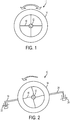
- FIGURE 1 schematically illustrates mechanical structure of a capacitive microelectromechanical system (MEMS)-based rotation sensor 10 according to one embodiment of the present disclosure.
- the MEMS-based design of the sensor 10 is advantageous due to its size, low power dissipation and low cost.
- the MEMS-based rotation sensor 10 includes a central anchor 12 coupled to a seismic mass 14 via a plurality of flexure springs 16.
- the central anchor 12 has a radius of approximately 300 ⁇ m, while the seismic mass 14 has a width of approximately 300 ⁇ m.
- the central anchor 12 and seismic mass 14 have other dimensions.
- the anchor 12 is coupled to the outside environment and thus experiences angular accelerations, which causes the seismic mass 14 to rotate due to inertial effects.
- the flexure springs 16 are able to bend, thus permitting rotation of the seismic mass 14 about anchor 12.
- the MEMS-based rotation sensor 10 includes a pair of beam-shaped electrodes 18, 20, which are disposed at opposing sides of the sensor.
- such electrodes 18, 20 have a length of 550 ⁇ m and a width of 5 ⁇ m.
- the beam-shaped electrodes 18, 20 have other dimensions.
- the pair of electrodes 18, 20 cooperate to detect differential capacitance resulting from angular displacement of the MEMS-based rotation sensor.
- electrode 18 is displaced from its origin position 22 as a result of the angular displacement of the seismic mass 14.
- Electrode 20 is also displaced in an opposite direction (relative to displacement of electrode 18) from its origin position 24 as a result of the displacement of the seismic mass 14.
- electrode 18 increases its capacitance of a quantity ⁇
- electrode 20 decreases its capacitance of the same quantity ⁇ .
- the capacitance difference of the two electrodes 18, 20 gives the capacitance variation quantity ⁇ , which is related to the rotation of the seismic mass 14.
- Angular displacements of the seismic mass 14 are thus converted into electrical signals using such a differential capacitor detector.
- the respective change in capacitance at the electrodes 18 and 20 may also be different quantities, may vary by a linear function, and may also vary by a non-linear function.
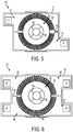
- a MEMS-based rotation sensor 30 is illustrated to include sliding comb electrodes 32, 34 which are used for detection of differential capacitance resulting from rotation of a seismic mass 36.
- the sliding comb electrodes 32, 34 have a finger length of 20 ⁇ m, a finger width of 3 ⁇ m, a comb length of 420 ⁇ m, and a comb width of 50 ⁇ m.
- the MEMS-based rotation sensor 30 further includes a central anchor 38 and flexural springs 39, which couple the seismic mass 36 to the central anchor.
- the comb electrodes 32, 34 generate electromechanical efforts in order to balance seismic angular displacements at the same time as differential capacitance detection.
- Capacitance variations of the MEMS-based rotation sensor 30 generate a current, which passes through a charge amplifier to obtain an output voltage.
- open-loop readout is achieved whereby the output voltage is proportional to the input angular accelerations measured by the MEMS-based rotation sensor 30.
- the MEMS-based rotation sensors described herein may be used with feedback control loop architecture that linearizes the force function with respect to a control voltage to thereby increase dynamic performances. This can be accomplished with analog control, digital control, or a combination thereof.
- An actuation signal such as a square wave, triangle wave, sinusoid, or other waveform may be applied to one or more electrodes (e.g., electrodes 32, 34).
- one or more of the electrodes e.g., electrodes 32, 34
- the electrical signal corresponding to angular acceleration may also be generated without an actuation signal.
- feedback control loop architecture 40 may include a sigma-delta modulator 42, which receives the electrical signal corresponding to angular acceleration and may be used to convert the measurement signal into a bit-stream voltage output.
- the output voltage may be passed through an integrator 44, a charge amplifier 46, and a proportional-integral-derivative (PID) controller 48 before applying a coarse quantization process 50.
- PID proportional-integral-derivative
- the analog signal may be converted into a bit-stream sequence.
- the bit-stream may then be sent to a force feedback generator 52, which may provide the actuation signal to electrodes of the MEMS-based rotation sensor (e.g., electrode 32) to create electrostatic forces proportional to the bit-stream average.
- the electrodes may be arranged such that a first set of the electrodes receive the actuation signal and a second set of the electrodes generate the electrical signal corresponding to angular acceleration. The first and second sets may or may not overlap. Some, or all, of the electrodes may receive the activation signal and also generate the electrical signal corresponding to angular acceleration.
- a MEMS-based rotation sensor 60 includes a seismic mass 62 disposed about a central anchor 64.
- the seismic mass 62 is coupled to the anchor 64 via a plurality of flexural springs 66.
- the MEMS-based rotation sensor 60 includes four flexural springs 66.
- the seismic mass 62 includes a plurality of electrodes 68 ( e.g., beam-shaped electrodes) extending from and adapted to move with the seismic mass.
- the MEMS-based rotation sensor 60 is disposed on a substrate 70, which includes a pair of fixed electrodes 72, 74 disposed at opposing sides of the seismic mass 62.
- a trench 76 separates the areas of the substrate 70 having the electrodes 72, 74.
- a MEMS-based rotation sensor 80 includes a seismic mass 82 coupled to a central anchor 84 via a plurality of flexural springs 86.
- the seismic mass 82 includes a plurality of electrodes 88 ( e.g., in a beam configuration) extending from and adapted to move with the seismic mass.
- electrodes 90, 92 are split and distributed around the seismic mass 82.
- the MEMS-based rotation sensor 80 is disposed on a substrate 92 and includes a pair of trenches 94, 96 to separate the areas of the substrate having the electrode sets 88, 90.
- the MEMS-based rotation sensor described herein may be used with a variety of other seismic sensors.
- the MEMS-based rotation sensor would measure the gradient of any signals measured by the translational accelerometer.
- the translational accelerometer may be a MEMS-based translational accelerometer that utilizes the same feedback control loop architecture 40 ( FIG. 4 ) as the MEMS-based rotation sensor.
- the MEMS-based rotation sensors described herein may be used in the seismic data acquisition context to reduce the number of sensor nodes and/or increase the spacing among such nodes, thus resulting in larger deployable arrays and/or lower operating costs. More particularly, the MEMS-based rotation sensors described herein may be used to measure the gradient of any signal acquired by translational accelerometers deployed in a seismic survey.
- surface waves e.g., ground roll waves
- Surface waves typical of land seismic operation noises have higher amplitudes due to their stronger energy and their small apparent wavelength at the free surface.
- the MEMS-based rotation sensors described herein are well-suited to measure the spatial gradients of noise components at the free surface. As a result of such gradient measurements, it is possible to interpolate noise components between sensor nodes, thus allowing for sparser spatial sampling. For example, rather than employing a standard Nyquist sampling 98 requiring two measurements for the shortest wavelength of a signal ( FIGURE 7 ), the MEMS-based rotation sensors according to the present disclosure permit Papoulis sampling 99, which only requires co-located measurements of the vertical wavefield and its gradient at each cycle for the shortest wavelength ( FIGURE 8 ). Accordingly, deploying MEMS-based rotation sensors according to the present disclosure requires less sensors for seismic data acquisition without compromising data quality.
- rotation measurement data may be used as a noise model for adaptive subtraction of ground roll noise.
- the MEMS-based rotation sensors described herein may be used in a variety of seismic data acquisition systems.
- an arrangement of sensor assemblies 100 that are used for land-based seismic surveying are deployed on a ground surface 102.
- the ground surface 102 overlies a geological formation 104 of interest, such as a hydrocarbon reservoir.
- One or more seismic sources 106 which can be vibrators, air guns, or explosive devices, are deployed in a survey field in which the sensor assemblies 100 are located.
- an exemplary sensory assembly 100 is illustrated to include a pair of MEMS-based rotation sensors (e.g., rotation sensor 60) according to the present disclosure as well as a MEMS-based translational accelerometer 110. It is to be appreciated that the MEMS-based rotation sensors 60 shown in FIG. 10 may be replaced with any MEMS-based rotation sensor disclosed herein. In the embodiment of FIG.
- the sensor assembly 100 includes the MEMS-based rotation sensors 60 positioned orthogonally to one another such that one of the MEMS-based rotation sensors measures the x-component of the horizontal gradient of the vertical wavefield and the other of the MEMS-based rotation sensor measures the y-component of the horizontal gradient of the vertical wavefield.
- the sensor assembly 100 may further include one or more spikes 112, or coupling elements, to improve coupling of the sensor assembly to the ground surface.
- the sensor assembly 100 may be entirely or partially inserted into the ground, proximate the surface, so as to be coupled to the ground and sensitive to ground roll.
- the sensor assembly 100 can extend across the ground surface.
- the sensor assemblies 100 are interconnected by an electrical cable 114 (or other type of communication medium) to a signal processing unit 150.
- the sensor assemblies can communicate wirelessly with the controller signal processing unit (for cable-free sensor assemblies).
- intermediate routers or concentrators may be provided at intermediate points of the network of sensor assemblies 100 to enable communication between the sensor assemblies and the signal processing unit 150.
- the signal processing unit 150 shown in FIG. 9 further includes processing software 152 that is executable on a processor 154.
- the processor 154 is connected to storage media 156 ( e.g., one or more disk-based storage devices and/or one or more memory devices).
- the storage media 156 is used to store sensor data 158, which includes output data produced by each of the sensor assemblies 100.
- the software 152 in the signal processing unit 150 is executable to process the sensor data 158 to produce an output to characterize the geological formation 104. It should be appreciated that the items in the processing unit 150 can be incorporated into the sensor units 100. This could be used in a "blind node" arrangement, where individual nodes are self contained with respect to collected data and/or power and/or communication.
- FIGURE 11 depicts an embodiment of a marine-based seismic data acquisition system 200 in accordance with some embodiments of the present disclosure.
- a survey vessel 202 tows one or more seismic streamers 204 (one exemplary streamer 204 being depicted in FIG. 11 ) behind the vessel.
- the streamers 204 may be arranged in a spread in which multiple streamers are towed in approximately the same plane at the same depth.
- the streamers 204 may be towed at multiple depths, such as in an over/under spread, for example.
- the seismic streamers 204 may be several thousand meters long and may contain various support cables (not shown), as well as wiring and/or circuitry (not shown) that may be used to support communication along the streamers.
- each streamer 204 includes a primary cable into which is mounted seismic sensors that record seismic signals.
- the streamers 204 contain seismic sensor units 206, which may include a hydrophone, particle motion sensors and the MEMS-based rotation sensor 10, 30, 60, 80 described herein.
- each sensor unit 206 is capable of detecting a pressure wavefield and at least one component of a particle motion that is associated with acoustic signals that are proximate to the sensor.
- Examples of particle motions include one or more components of a particle displacement, one or more components (inline (x), crossline (y) and vertical (z) components) of a particle velocity and one or more components of a particle acceleration.
- Each sensor unit 206 is further capable of detecting angular accelerations of vibration noise.
- the sensor units 206 may include one or more hydrophones, geophones, particle displacement sensors, particle velocity sensors, accelerometers, pressure gradient sensors, rotation sensors or combinations thereof.
- the sensor units 206 may include a capacitive microelectromechanical system (MEMS)-based sensor that is sensitive to translational accelerations and the MEMS-based rotation sensor 10, 30, 60, 80 that is sensitive to angular accelerations.
- MEMS microelectromechanical system
- the marine seismic data acquisition system 200 further includes seismic sources 208 (two exemplary seismic sources 208 being depicted in FIG. 11 ), such as air guns and the like.
- the seismic sources 208 may be coupled to, or towed by, the survey vessel 202.
- the seismic sources 208 may operate independently of the survey vessel 202, in that the sources may be coupled to other vessels or buoys.
- acoustic signals 210 are produced by the seismic sources 208 and are directed down through a water column 212 into strata 214 and 216 beneath a water bottom surface 218.
- the acoustic signals 210 are reflected from the various subterranean geological formations, such as an exemplary formation 220 that is depicted in FIG. 11 .
- the incident acoustic signals 210 that are created by the sources 208 produce corresponding reflected acoustic signals, or pressure waves 222, which are sensed by the seismic sensors of the streamer(s) 204.
- the pressure waves that are received and sensed by the seismic sensors include "up going" pressure waves that propagate to the sensors without reflection, as well as “down going” pressure waves that are produced by reflections of the pressure waves 222 from an air-water boundary, or free surface 224.
- the seismic sensors of the streamer(s) 204 generate signals (digital signals, for example), called "traces," which indicate the acquired measurements of the pressure wavefield and particle motion.
- the traces are recorded and may be at least partially processed by a signal processing unit 226 (e.g., a unit the same or similar to the signal processing unit 150 of FIG. 9 ) that is deployed on the survey vessel 202, in accordance with some embodiments of the present disclosure.
- a signal processing unit 226 e.g., a unit the same or similar to the signal processing unit 150 of FIG. 9
- a particular multi-component sensor may provide a trace, which corresponds to a measure of a pressure wavefield by its hydrophone; and the sensor may provide one or more traces that correspond to one or more components of particle motion.
- the sensor unit may further sense angular accelerations via the MEMS-based rotation sensor described herein. Such measurements facilitate the removal of transverse vibration noise.
- the goal of the seismic acquisition is to build up an image of a survey area for purposes of identifying subterranean geological formations, such as the exemplary geological formation 220.
- Subsequent analysis of the representation may reveal probable locations of hydrocarbon deposits in subterranean geological formations.
- portions of the analysis of the representation may be performed on the seismic survey vessel 202, such as by the signal processing unit 226.
- the representation may be processed by a seismic data processing system located remotely of the vessel 202.
- MEMS-based rotation sensor 10 is described for use in seismic data acquisition systems, it is to be appreciated that the sensor may be used in other data acquisition systems outside of the field of seismic data acquisition.
- the breadth and scope of the present disclosure should not be limited by any of the above-described exemplary embodiments, but should be defined only in accordance with the following claims and their equivalents.
- the above advantages and features are provided in described embodiments, but shall not limit the application of the claims to processes and structures accomplishing any or all of the above advantages.
Landscapes
- Life Sciences & Earth Sciences (AREA)
- Physics & Mathematics (AREA)
- Remote Sensing (AREA)
- Engineering & Computer Science (AREA)
- General Physics & Mathematics (AREA)
- General Life Sciences & Earth Sciences (AREA)
- Environmental & Geological Engineering (AREA)
- Geology (AREA)
- Acoustics & Sound (AREA)
- Geophysics (AREA)
- Oceanography (AREA)
- Geophysics And Detection Of Objects (AREA)
- Gyroscopes (AREA)
Claims (12)
- Seismisches Datenerfassungssystem, das umfasst:eine oder mehrere Quellen (106) zum Erzeugen seismischer Wellen; undeine oder mehrere Sensoreinheiten (100, 206) zum Aufzeichnen von den Quellen (106) erzeugter seismischer Wellen,wobei die eine oder die mehreren Sensoreinheiten (100, 206) einen ersten seismischen Sensor zum Messen eines vertikalen Wellenfeldes der seismischen Wellen und einen zweiten seismischen Sensor zum Messen eines Gradienten des vertikalen Wellenfeldes aufweisen; gekennzeichnet durch
ein Gehäuse, wobei der erste seismische Sensor und der zweite seismische Sensor im Gehäuse angeordnet sind,
wobei der zweite Sensor ein MEMS-basierter Rotationssensor (10, 30, 60, 80) ist; und wobei der MEMS-basierte Rotationssensor (10, 30, 60, 80) umfasst:ein Substrat;eine zentrale Verankerung (12, 38, 64, 84), die auf dem Substrat angeordnet ist;eine seismische Masse (14, 36, 62, 82), die mit der zentralen Verankerung über eine Mehrzahl von Biegefedern (16, 39, 66, 86) gekoppelt ist, wobei die seismische Masse (14, 36, 62, 82) eine erste Elektrode (18, 32) aufweist, die mit der seismischen Masse gekoppelt ist und sich von dieser erstreckt;eine zweite Elektrode (20, 34), die am Substrat festgelegt ist, wobei eine der ersten und zweiten Elektrode (18, 20, 32, 34) dazu ausgelegt ist, ein Ansteuersignal zu empfangen, und eine andere der ersten und zweiten Elektrode (18, 20, 32, 34) dazu ausgelegt ist, ein elektrisches Signal zu erzeugen, das eine Amplitude aufweist, die einem Grad einer Winkelbewegung der ersten Elektrode (18, 32) relativ zur zweiten Elektrode (20; 34) entspricht; undein geschlossenes Regelkreissystem (40), das dazu ausgelegt ist, das elektrischeSignal zu empfangen und das Ansteuersignal bereitzustellen, undwobei wenigstens eine der ersten und zweiten Elektrode (18, 20, 32, 34) eine Balkenform umfasst, wobei eine Länge der Elektroden größer als eine Breite der seismischen Masse (14, 36, 62, 82) ist. - Seismisches Datenerfassungssystem gemäß Anspruch 1, wobei der erste seismische Sensor ein Einkomponenten-Teilchenbewegungssensor ist.
- Seismisches Datenerfassungssystem gemäß Anspruch 1, wobei der erste seismische Sensor ein Dreikomponenten-Teilchenbewegungssensor ist.
- Seismisches Datenerfassungssystem gemäß Anspruch 1, das ferner einen dritten Sensor zum Messen eines Gradienten des vertikalen Wellenfeldes umfasst, wobei der dritte Sensor ein zum zweiten Sensor orthogonal positionierter MEMS-basierter Rotationssensor ist.
- Seismisches Datenerfassungssystem gemäß Anspruch 1, wobei die elektrischen Signale analoge Signale sind und das geschlossene Regelkreissystem (40) Mittel zum Umwandeln der analogen Signale in jeweilige Bitstream-Sequenzen umfasst.
- Seismisches Datenerfassungssystem gemäß Anspruch 5, wobei das geschlossene Regelkreissystem ferner einen Kraftrückführungsgenerator (52) zum Empfangen der jeweiligen Bitstream-Sequenzen und Umwandeln der jeweiligen Bitstream-Sequenzen in das Ansteuersignal umfasst.
- Seismisches Datenerfassungssystem gemäß Anspruch 1, wobei das seismische Datenerfassungssystem ein landgestütztes seismisches Datenerfassungssystem ist.
- Seismisches Datenerfassungssystem gemäß Anspruch 1, wobei das seismische Datenerfassungssystem ein marinegestütztes seismisches Datenerfassungssystem ist.
- Verfahren zum Durchführen einer seismischen Datenerfassung, das umfasst:Erzeugen seismischer Wellen unter Verwendung einer oder mehrerer Quellen (106);Aufzeichnen von den Quellen erzeugter seismischer Wellen unter Verwendung einer oder mehrerer Sensoreinheiten (100, 206), die einen ersten seismischen Sensor zum Messen eines vertikalen Wellenfeldes der seismischen Wellen und einen zweiten seismischen Sensor zum Messen eines Gradienten des vertikalen Wellenfeldes aufweisen, dadurch gekennzeichnet, dass der erste seismische Sensor und der zweite seismische Sensor in einem Gehäuse angeordnet sind, der zweite seismische Sensor ein MEMS-basierter Rotationssensor (10, 30, 60, 80) ist; undwobei der MEMS-basierte Rotationssensor (10, 30, 60, 80) umfasst:ein Substrat;eine zentrale Verankerung (12, 38, 64, 84), die auf dem Substrat angeordnet ist;eine seismische Masse (14, 36, 62, 82), die mit der zentralen Verankerung (12, 38, 64, 84) über eine Mehrzahl von Biegefedern (16, 39, 66, 86) gekoppelt ist, wobei die seismische Masse (14, 36, 62, 82) eine erste Elektrode aufweist, die mit der seismischen Masse (14, 36, 62, 82) gekoppelt ist und sich von dieser erstreckt;eine zweite Elektrode (20, 34), die am Substrat festgelegt ist, wobei eine der ersten und zweiten Elektrode (18, 20, 32, 34) dazu ausgelegt ist, ein Ansteuersignal zu empfangen, und eine andere der ersten und zweiten Elektrode (18, 20, 32, 34) dazu ausgelegt ist, ein elektrisches Signal zu erzeugen, das eine Amplitude aufweist, die einem Grad einer Winkelbewegung der ersten (18, 32) relativ zur zweiten Elektrode (20; 34) entspricht; undein geschlossenes Regelkreissystem (40), das dazu ausgelegt ist, das elektrische Signal zu empfangen und das Ansteuersignal bereitzustellen, und wobei wenigstens eine der ersten und zweiten Elektrode (18, 20, 32, 34) eine Balkenform umfasst,wobei eine Länge der Elektroden größer als eine Breite der seismischen Masse (14, 36, 62, 82) ist.
- Verfahren gemäß Anspruch 9, wobei der erste seismische Sensor ein MEMS-basierter translatorischer Beschleunigungsmesser zum Messen des vertikalen Wellenfeldes ist.
- Verfahren gemäß Anspruch 9, wobei die seismische Datenerfassung in einer Landumgebung durchgeführt wird.
- Verfahren gemäß Anspruch 9, wobei die seismische Datenerfassung in einer marinen Umgebung durchgeführt wird.
Applications Claiming Priority (3)
| Application Number | Priority Date | Filing Date | Title |
|---|---|---|---|
| US201261739602P | 2012-12-19 | 2012-12-19 | |
| US14/104,806 US9547095B2 (en) | 2012-12-19 | 2013-12-12 | MEMS-based rotation sensor for seismic applications and sensor units having same |
| PCT/US2013/075396 WO2014099786A1 (en) | 2012-12-19 | 2013-12-16 | Mems-based rotation sensor for seismic applications and sensor units having same |
Publications (3)
| Publication Number | Publication Date |
|---|---|
| EP2936209A1 EP2936209A1 (de) | 2015-10-28 |
| EP2936209A4 EP2936209A4 (de) | 2016-01-06 |
| EP2936209B1 true EP2936209B1 (de) | 2018-11-28 |
Family
ID=50979080
Family Applications (1)
| Application Number | Title | Priority Date | Filing Date |
|---|---|---|---|
| EP13865987.5A Active EP2936209B1 (de) | 2012-12-19 | 2013-12-16 | Mems-basierter rotationssensor für seismische anwendungen und sensoreinheiten damit |
Country Status (8)
| Country | Link |
|---|---|
| US (4) | US9547095B2 (de) |
| EP (1) | EP2936209B1 (de) |
| CN (1) | CN105026959B (de) |
| AU (1) | AU2013363143A1 (de) |
| BR (1) | BR112015014826B1 (de) |
| CA (1) | CA2895190A1 (de) |
| MX (1) | MX342870B (de) |
| WO (1) | WO2014099786A1 (de) |
Families Citing this family (20)
| Publication number | Priority date | Publication date | Assignee | Title |
|---|---|---|---|---|
| US9547095B2 (en) | 2012-12-19 | 2017-01-17 | Westerngeco L.L.C. | MEMS-based rotation sensor for seismic applications and sensor units having same |
| US9417346B2 (en) * | 2013-08-29 | 2016-08-16 | Westerngeco L.L.C. | Seismic vibrator device and method with rotation sensor |
| EP3137926A4 (de) | 2014-04-28 | 2017-12-13 | Westerngeco LLC | Rekonstruktion eines wellenfeldes |
| NO347442B1 (en) * | 2014-12-08 | 2023-11-06 | Schlumberger Technology Bv | A seismic sensor unit, a system for seismic surveying and a method for processing seismic data |
| DE102015207637A1 (de) * | 2015-04-27 | 2016-10-27 | Robert Bosch Gmbh | Mikromechanische Struktur für einen Beschleunigungssensor |
| MX381934B (es) | 2015-05-01 | 2025-03-13 | Reflection Marine Norge As | Prospección con fuentes directivas de vibradores marinos. |
| WO2016179206A1 (en) | 2015-05-05 | 2016-11-10 | Schlumberger Technology Corporation | Removal of acquisition effects from marine seismic data |
| BR112018007364A2 (pt) | 2015-11-17 | 2018-10-23 | Halliburton Energy Services Inc | sistema e método microeletromecânico (mem) para detectar propriedades de furo de poço |
| MX392202B (es) | 2015-12-02 | 2025-03-21 | Schlumberger Technology Bv | Tendido de sensores sismicos terrestres con pares de sensores sismicos de multiples componentes adyacentes en promedio a una distancia de al menos veinte metros. |
| CN105759075B (zh) * | 2016-02-25 | 2017-09-19 | 中国科学院地质与地球物理研究所 | 一种高精度挠性加速度计 |
| CN105783853B (zh) * | 2016-03-03 | 2018-05-15 | 浙江大学 | 一种可用于水下载具定位的缆绳的形变监测系统 |
| GB2566240A (en) | 2016-06-15 | 2019-03-06 | Schlumberger Technology Bv | Systems and methods for acquiring seismic data with gradient data |
| CN106199688B (zh) * | 2016-06-29 | 2018-02-23 | 成都理工大学 | 集成有主动震源的高精度三分量微地震检波器及实现方法 |
| CN105973453A (zh) * | 2016-07-25 | 2016-09-28 | 重庆大学 | 一种新型三轴绝对扭转振动传感器 |
| CN106123841A (zh) * | 2016-07-25 | 2016-11-16 | 重庆大学 | 一种新型三轴绝对扭转振动传感器结构 |
| US20190101662A1 (en) * | 2017-10-04 | 2019-04-04 | Westerngeco Llc | Compressive sensing marine streamer system |
| CN108363094B (zh) * | 2018-04-20 | 2023-10-10 | 湖北省地震局 | 旋转地震计 |
| US11820648B2 (en) * | 2018-05-15 | 2023-11-21 | Murata Manufacturing Co., Ltd. | Vibration damping in MEMS acceleration sensors |
| CN112682054B (zh) * | 2020-12-03 | 2022-08-23 | 重庆文理学院 | 一种用于tbm施工监测的挖掘设备及其勘测方法 |
| IT202100024644A1 (it) * | 2021-09-27 | 2023-03-27 | St Microelectronics Srl | Circuito di controllo di un giroscopio mems, giroscopio mems e metodo di controllo |
Family Cites Families (39)
| Publication number | Priority date | Publication date | Assignee | Title |
|---|---|---|---|---|
| US2657373A (en) * | 1949-09-06 | 1953-10-27 | Phillips Petroleum Co | Apparatus for seismic exploration |
| US5734104A (en) * | 1993-08-16 | 1998-03-31 | Panenka; Jerry R. | Laplace gravity gradiometer |
| US7711672B2 (en) * | 1998-05-28 | 2010-05-04 | Lawrence Au | Semantic network methods to disambiguate natural language meaning |
| DE19938206A1 (de) * | 1999-08-12 | 2001-02-15 | Bosch Gmbh Robert | Mikromechanischer Drehbeschleunigungssensor |
| WO2001069266A1 (en) * | 2000-03-13 | 2001-09-20 | Microsensors, Inc. | Method of driving mems sensor with balanced four-phase comb drive |
| US6885918B2 (en) * | 2000-06-15 | 2005-04-26 | Geo-X Systems, Ltd. | Seismic monitoring and control method |
| WO2002050874A2 (en) * | 2000-12-19 | 2002-06-27 | Coventor, Incorporated | Mems device having an actuator with curved electrodes |
| US6393914B1 (en) | 2001-02-13 | 2002-05-28 | Delphi Technologies, Inc. | Angular accelerometer |
| WO2002088631A2 (en) | 2001-05-02 | 2002-11-07 | The Regents Of The University Of California | Non-resonant four degrees-of-freedom micromachined gyroscope |
| US20020189351A1 (en) * | 2001-06-14 | 2002-12-19 | Reeds John W. | Angular rate sensor having a sense element constrained to motion about a single axis and flexibly attached to a rotary drive mass |
| US6513380B2 (en) * | 2001-06-19 | 2003-02-04 | Microsensors, Inc. | MEMS sensor with single central anchor and motion-limiting connection geometry |
| US6776042B2 (en) * | 2002-01-25 | 2004-08-17 | Kinemetrics, Inc. | Micro-machined accelerometer |
| US7239577B2 (en) | 2002-08-30 | 2007-07-03 | Pgs Americas, Inc. | Apparatus and methods for multicomponent marine geophysical data gathering |
| AU2003276913A1 (en) * | 2002-09-18 | 2004-04-08 | Carnegie Mellon University | Built-in self test of mems |
| US7137300B2 (en) * | 2003-03-19 | 2006-11-21 | California Institute Of Technology | Parylene capacitive accelerometer utilizing electrical fringing field sensing and method of making |
| US7100446B1 (en) * | 2004-07-20 | 2006-09-05 | The Regents Of The University Of California | Distributed-mass micromachined gyroscopes operated with drive-mode bandwidth enhancement |
| JP4353087B2 (ja) * | 2004-12-01 | 2009-10-28 | 株式会社デンソー | 回転振動型角速度センサ |
| US7656746B2 (en) * | 2005-04-08 | 2010-02-02 | Westerngeco L.L.C. | Rational motion compensated seabed seismic sensors and methods of use in seabed seismic data acquisition |
| US8477561B2 (en) | 2005-04-26 | 2013-07-02 | Westerngeco L.L.C. | Seismic streamer system and method |
| GB2428089B (en) * | 2005-07-05 | 2008-11-05 | Schlumberger Holdings | Borehole seismic acquisition system using pressure gradient sensors |
| US7623414B2 (en) | 2006-02-22 | 2009-11-24 | Westerngeco L.L.C. | Particle motion vector measurement in a towed, marine seismic cable |
| US7549334B2 (en) * | 2006-04-24 | 2009-06-23 | Milli Sensor Systems + Actuators | Small angle bias measurement mechanism for MEMS instruments |
| US8250921B2 (en) * | 2007-07-06 | 2012-08-28 | Invensense, Inc. | Integrated motion processing unit (MPU) with MEMS inertial sensing and embedded digital electronics |
| US7843765B2 (en) * | 2007-08-09 | 2010-11-30 | Westerngeco L.L.C. | Attenuating a surface seismic wave |
| US8042394B2 (en) * | 2007-09-11 | 2011-10-25 | Stmicroelectronics S.R.L. | High sensitivity microelectromechanical sensor with rotary driving motion |
| GB0720412D0 (en) * | 2007-10-18 | 2007-11-28 | Melexis Nv | Combined mems accelerometer and gyroscope |
| GB2456313B (en) * | 2008-01-10 | 2010-05-12 | Westerngeco Seismic Holdings | Sensor devices |
| BRPI0912057B1 (pt) * | 2008-08-08 | 2020-09-15 | Assa Abloy Ab | Mecanismo de sensor direcional e autenticação de comunicações |
| US8104346B2 (en) * | 2008-11-10 | 2012-01-31 | Westerngeco L.L.C. | MEMS-based capacitive sensor |
| IT1391972B1 (it) * | 2008-11-26 | 2012-02-02 | St Microelectronics Rousset | Giroscopio microelettromeccanico con movimento di azionamento rotatorio e migliorate caratteristiche elettriche |
| IT1392741B1 (it) * | 2008-12-23 | 2012-03-16 | St Microelectronics Rousset | Giroscopio microelettromeccanico con migliorata reiezione di disturbi di accelerazione |
| US9304216B2 (en) * | 2009-02-05 | 2016-04-05 | Westerngeco L.L.C. | Seismic acquisition system and technique |
| US8534127B2 (en) * | 2009-09-11 | 2013-09-17 | Invensense, Inc. | Extension-mode angular velocity sensor |
| US8322216B2 (en) | 2009-09-22 | 2012-12-04 | Duli Yu | Micromachined accelerometer with monolithic electrodes and method of making the same |
| US20110228635A1 (en) | 2010-03-22 | 2011-09-22 | Pgs Geophysical As | Self-positioning nodal geophysical recorder |
| US8654606B2 (en) | 2010-07-27 | 2014-02-18 | Westerngeco L.L.C. | Obtaining a response based on differencing of outputs of sensors |
| US20120250460A1 (en) | 2011-04-04 | 2012-10-04 | Pascal Edme | Noise attenuation using rotation data |
| US8875578B2 (en) * | 2011-10-26 | 2014-11-04 | Silicon Laboratories Inc. | Electronic damper circuit for MEMS sensors and resonators |
| US9547095B2 (en) | 2012-12-19 | 2017-01-17 | Westerngeco L.L.C. | MEMS-based rotation sensor for seismic applications and sensor units having same |
-
2013
- 2013-12-12 US US14/104,806 patent/US9547095B2/en active Active
- 2013-12-16 AU AU2013363143A patent/AU2013363143A1/en not_active Abandoned
- 2013-12-16 MX MX2015007892A patent/MX342870B/es active IP Right Grant
- 2013-12-16 EP EP13865987.5A patent/EP2936209B1/de active Active
- 2013-12-16 WO PCT/US2013/075396 patent/WO2014099786A1/en not_active Ceased
- 2013-12-16 BR BR112015014826-3A patent/BR112015014826B1/pt active IP Right Grant
- 2013-12-16 CA CA2895190A patent/CA2895190A1/en not_active Abandoned
- 2013-12-16 CN CN201380071994.XA patent/CN105026959B/zh active Active
-
2017
- 2017-01-16 US US15/407,241 patent/US10451753B2/en active Active
-
2019
- 2019-10-18 US US16/657,563 patent/US11487031B2/en active Active
-
2022
- 2022-10-27 US US18/050,248 patent/US12111434B2/en active Active
Non-Patent Citations (1)
| Title |
|---|
| None * |
Also Published As
| Publication number | Publication date |
|---|---|
| CN105026959A (zh) | 2015-11-04 |
| EP2936209A1 (de) | 2015-10-28 |
| MX342870B (es) | 2016-10-17 |
| MX2015007892A (es) | 2015-10-12 |
| AU2013363143A1 (en) | 2015-07-09 |
| US9547095B2 (en) | 2017-01-17 |
| WO2014099786A1 (en) | 2014-06-26 |
| US20200049843A1 (en) | 2020-02-13 |
| CN105026959B (zh) | 2018-05-18 |
| EP2936209A4 (de) | 2016-01-06 |
| US20230070241A1 (en) | 2023-03-09 |
| BR112015014826A2 (pt) | 2017-07-11 |
| BR112015014826B1 (pt) | 2022-03-29 |
| US12111434B2 (en) | 2024-10-08 |
| US10451753B2 (en) | 2019-10-22 |
| US20170261626A1 (en) | 2017-09-14 |
| US20150316667A1 (en) | 2015-11-05 |
| US11487031B2 (en) | 2022-11-01 |
| CA2895190A1 (en) | 2014-06-26 |
Similar Documents
| Publication | Publication Date | Title |
|---|---|---|
| US12111434B2 (en) | MEMS-based rotation sensor for seismic applications and sensor units having same | |
| CN102265184B (zh) | 基于mems的电容传感器 | |
| US8645071B2 (en) | Direct velocity seismic sensing | |
| US20140112094A1 (en) | Direct velocity seismic sensing | |
| US10962667B2 (en) | Data-driven clock drift adjustment | |
| WO2004065986A2 (en) | A marine seismic acquisition method and apparatus | |
| US9010170B2 (en) | Method and apparatus to test an accelerometer | |
| US20140269180A1 (en) | Gravity Measurements By Towed Streamers | |
| WO2014152151A1 (en) | Determining a seismic vibrator signature | |
| CA3010138C (en) | Data-driven clock drift adjustment |
Legal Events
| Date | Code | Title | Description |
|---|---|---|---|
| PUAI | Public reference made under article 153(3) epc to a published international application that has entered the european phase |
Free format text: ORIGINAL CODE: 0009012 |
|
| 17P | Request for examination filed |
Effective date: 20150612 |
|
| AK | Designated contracting states |
Kind code of ref document: A1 Designated state(s): AL AT BE BG CH CY CZ DE DK EE ES FI FR GB GR HR HU IE IS IT LI LT LU LV MC MK MT NL NO PL PT RO RS SE SI SK SM TR |
|
| AX | Request for extension of the european patent |
Extension state: BA ME |
|
| A4 | Supplementary search report drawn up and despatched |
Effective date: 20151203 |
|
| RIC1 | Information provided on ipc code assigned before grant |
Ipc: G01V 1/18 20060101ALI20151127BHEP Ipc: G01V 1/24 20060101ALI20151127BHEP Ipc: G01V 1/38 20060101AFI20151127BHEP |
|
| 17Q | First examination report despatched |
Effective date: 20151216 |
|
| DAX | Request for extension of the european patent (deleted) | ||
| RIN1 | Information on inventor provided before grant (corrected) |
Inventor name: VANCAUWENBERGHE, OLIVIER Inventor name: GOUJON, NICOLAS Inventor name: PAULSON, HANS Inventor name: PROJETTI, MAXIME |
|
| GRAP | Despatch of communication of intention to grant a patent |
Free format text: ORIGINAL CODE: EPIDOSNIGR1 |
|
| INTG | Intention to grant announced |
Effective date: 20180629 |
|
| GRAS | Grant fee paid |
Free format text: ORIGINAL CODE: EPIDOSNIGR3 |
|
| GRAA | (expected) grant |
Free format text: ORIGINAL CODE: 0009210 |
|
| AK | Designated contracting states |
Kind code of ref document: B1 Designated state(s): AL AT BE BG CH CY CZ DE DK EE ES FI FR GB GR HR HU IE IS IT LI LT LU LV MC MK MT NL NO PL PT RO RS SE SI SK SM TR |
|
| REG | Reference to a national code |
Ref country code: CH Ref legal event code: EP |
|
| REG | Reference to a national code |
Ref country code: AT Ref legal event code: REF Ref document number: 1070883 Country of ref document: AT Kind code of ref document: T Effective date: 20181215 |
|
| REG | Reference to a national code |
Ref country code: DE Ref legal event code: R096 Ref document number: 602013047613 Country of ref document: DE |
|
| REG | Reference to a national code |
Ref country code: IE Ref legal event code: FG4D |
|
| REG | Reference to a national code |
Ref country code: NL Ref legal event code: MP Effective date: 20181128 |
|
| REG | Reference to a national code |
Ref country code: LT Ref legal event code: MG4D |
|
| REG | Reference to a national code |
Ref country code: AT Ref legal event code: MK05 Ref document number: 1070883 Country of ref document: AT Kind code of ref document: T Effective date: 20181128 |
|
| PG25 | Lapsed in a contracting state [announced via postgrant information from national office to epo] |
Ref country code: HR Free format text: LAPSE BECAUSE OF FAILURE TO SUBMIT A TRANSLATION OF THE DESCRIPTION OR TO PAY THE FEE WITHIN THE PRESCRIBED TIME-LIMIT Effective date: 20181128 Ref country code: BG Free format text: LAPSE BECAUSE OF FAILURE TO SUBMIT A TRANSLATION OF THE DESCRIPTION OR TO PAY THE FEE WITHIN THE PRESCRIBED TIME-LIMIT Effective date: 20190228 Ref country code: FI Free format text: LAPSE BECAUSE OF FAILURE TO SUBMIT A TRANSLATION OF THE DESCRIPTION OR TO PAY THE FEE WITHIN THE PRESCRIBED TIME-LIMIT Effective date: 20181128 Ref country code: LT Free format text: LAPSE BECAUSE OF FAILURE TO SUBMIT A TRANSLATION OF THE DESCRIPTION OR TO PAY THE FEE WITHIN THE PRESCRIBED TIME-LIMIT Effective date: 20181128 Ref country code: LV Free format text: LAPSE BECAUSE OF FAILURE TO SUBMIT A TRANSLATION OF THE DESCRIPTION OR TO PAY THE FEE WITHIN THE PRESCRIBED TIME-LIMIT Effective date: 20181128 Ref country code: ES Free format text: LAPSE BECAUSE OF FAILURE TO SUBMIT A TRANSLATION OF THE DESCRIPTION OR TO PAY THE FEE WITHIN THE PRESCRIBED TIME-LIMIT Effective date: 20181128 Ref country code: IS Free format text: LAPSE BECAUSE OF FAILURE TO SUBMIT A TRANSLATION OF THE DESCRIPTION OR TO PAY THE FEE WITHIN THE PRESCRIBED TIME-LIMIT Effective date: 20190328 Ref country code: AT Free format text: LAPSE BECAUSE OF FAILURE TO SUBMIT A TRANSLATION OF THE DESCRIPTION OR TO PAY THE FEE WITHIN THE PRESCRIBED TIME-LIMIT Effective date: 20181128 |
|
| REG | Reference to a national code |
Ref country code: NO Ref legal event code: T2 Effective date: 20181128 |
|
| PG25 | Lapsed in a contracting state [announced via postgrant information from national office to epo] |
Ref country code: RS Free format text: LAPSE BECAUSE OF FAILURE TO SUBMIT A TRANSLATION OF THE DESCRIPTION OR TO PAY THE FEE WITHIN THE PRESCRIBED TIME-LIMIT Effective date: 20181128 Ref country code: PT Free format text: LAPSE BECAUSE OF FAILURE TO SUBMIT A TRANSLATION OF THE DESCRIPTION OR TO PAY THE FEE WITHIN THE PRESCRIBED TIME-LIMIT Effective date: 20190328 Ref country code: GR Free format text: LAPSE BECAUSE OF FAILURE TO SUBMIT A TRANSLATION OF THE DESCRIPTION OR TO PAY THE FEE WITHIN THE PRESCRIBED TIME-LIMIT Effective date: 20190301 Ref country code: SE Free format text: LAPSE BECAUSE OF FAILURE TO SUBMIT A TRANSLATION OF THE DESCRIPTION OR TO PAY THE FEE WITHIN THE PRESCRIBED TIME-LIMIT Effective date: 20181128 Ref country code: AL Free format text: LAPSE BECAUSE OF FAILURE TO SUBMIT A TRANSLATION OF THE DESCRIPTION OR TO PAY THE FEE WITHIN THE PRESCRIBED TIME-LIMIT Effective date: 20181128 |
|
| PG25 | Lapsed in a contracting state [announced via postgrant information from national office to epo] |
Ref country code: NL Free format text: LAPSE BECAUSE OF FAILURE TO SUBMIT A TRANSLATION OF THE DESCRIPTION OR TO PAY THE FEE WITHIN THE PRESCRIBED TIME-LIMIT Effective date: 20181128 |
|
| PG25 | Lapsed in a contracting state [announced via postgrant information from national office to epo] |
Ref country code: PL Free format text: LAPSE BECAUSE OF FAILURE TO SUBMIT A TRANSLATION OF THE DESCRIPTION OR TO PAY THE FEE WITHIN THE PRESCRIBED TIME-LIMIT Effective date: 20181128 Ref country code: DK Free format text: LAPSE BECAUSE OF FAILURE TO SUBMIT A TRANSLATION OF THE DESCRIPTION OR TO PAY THE FEE WITHIN THE PRESCRIBED TIME-LIMIT Effective date: 20181128 Ref country code: IT Free format text: LAPSE BECAUSE OF FAILURE TO SUBMIT A TRANSLATION OF THE DESCRIPTION OR TO PAY THE FEE WITHIN THE PRESCRIBED TIME-LIMIT Effective date: 20181128 Ref country code: CZ Free format text: LAPSE BECAUSE OF FAILURE TO SUBMIT A TRANSLATION OF THE DESCRIPTION OR TO PAY THE FEE WITHIN THE PRESCRIBED TIME-LIMIT Effective date: 20181128 |
|
| REG | Reference to a national code |
Ref country code: CH Ref legal event code: PL |
|
| REG | Reference to a national code |
Ref country code: DE Ref legal event code: R097 Ref document number: 602013047613 Country of ref document: DE |
|
| PG25 | Lapsed in a contracting state [announced via postgrant information from national office to epo] |
Ref country code: SK Free format text: LAPSE BECAUSE OF FAILURE TO SUBMIT A TRANSLATION OF THE DESCRIPTION OR TO PAY THE FEE WITHIN THE PRESCRIBED TIME-LIMIT Effective date: 20181128 Ref country code: MC Free format text: LAPSE BECAUSE OF FAILURE TO SUBMIT A TRANSLATION OF THE DESCRIPTION OR TO PAY THE FEE WITHIN THE PRESCRIBED TIME-LIMIT Effective date: 20181128 Ref country code: EE Free format text: LAPSE BECAUSE OF FAILURE TO SUBMIT A TRANSLATION OF THE DESCRIPTION OR TO PAY THE FEE WITHIN THE PRESCRIBED TIME-LIMIT Effective date: 20181128 Ref country code: SM Free format text: LAPSE BECAUSE OF FAILURE TO SUBMIT A TRANSLATION OF THE DESCRIPTION OR TO PAY THE FEE WITHIN THE PRESCRIBED TIME-LIMIT Effective date: 20181128 Ref country code: RO Free format text: LAPSE BECAUSE OF FAILURE TO SUBMIT A TRANSLATION OF THE DESCRIPTION OR TO PAY THE FEE WITHIN THE PRESCRIBED TIME-LIMIT Effective date: 20181128 Ref country code: LU Free format text: LAPSE BECAUSE OF NON-PAYMENT OF DUE FEES Effective date: 20181216 |
|
| REG | Reference to a national code |
Ref country code: IE Ref legal event code: MM4A |
|
| REG | Reference to a national code |
Ref country code: BE Ref legal event code: MM Effective date: 20181231 |
|
| PLBE | No opposition filed within time limit |
Free format text: ORIGINAL CODE: 0009261 |
|
| STAA | Information on the status of an ep patent application or granted ep patent |
Free format text: STATUS: NO OPPOSITION FILED WITHIN TIME LIMIT |
|
| PG25 | Lapsed in a contracting state [announced via postgrant information from national office to epo] |
Ref country code: IE Free format text: LAPSE BECAUSE OF NON-PAYMENT OF DUE FEES Effective date: 20181216 Ref country code: SI Free format text: LAPSE BECAUSE OF FAILURE TO SUBMIT A TRANSLATION OF THE DESCRIPTION OR TO PAY THE FEE WITHIN THE PRESCRIBED TIME-LIMIT Effective date: 20181128 |
|
| 26N | No opposition filed |
Effective date: 20190829 |
|
| PG25 | Lapsed in a contracting state [announced via postgrant information from national office to epo] |
Ref country code: BE Free format text: LAPSE BECAUSE OF NON-PAYMENT OF DUE FEES Effective date: 20181231 |
|
| PG25 | Lapsed in a contracting state [announced via postgrant information from national office to epo] |
Ref country code: CH Free format text: LAPSE BECAUSE OF NON-PAYMENT OF DUE FEES Effective date: 20181231 Ref country code: LI Free format text: LAPSE BECAUSE OF NON-PAYMENT OF DUE FEES Effective date: 20181231 |
|
| PG25 | Lapsed in a contracting state [announced via postgrant information from national office to epo] |
Ref country code: MT Free format text: LAPSE BECAUSE OF NON-PAYMENT OF DUE FEES Effective date: 20181216 |
|
| PG25 | Lapsed in a contracting state [announced via postgrant information from national office to epo] |
Ref country code: TR Free format text: LAPSE BECAUSE OF FAILURE TO SUBMIT A TRANSLATION OF THE DESCRIPTION OR TO PAY THE FEE WITHIN THE PRESCRIBED TIME-LIMIT Effective date: 20181128 |
|
| PG25 | Lapsed in a contracting state [announced via postgrant information from national office to epo] |
Ref country code: CY Free format text: LAPSE BECAUSE OF FAILURE TO SUBMIT A TRANSLATION OF THE DESCRIPTION OR TO PAY THE FEE WITHIN THE PRESCRIBED TIME-LIMIT Effective date: 20181128 Ref country code: MK Free format text: LAPSE BECAUSE OF NON-PAYMENT OF DUE FEES Effective date: 20181128 Ref country code: HU Free format text: LAPSE BECAUSE OF FAILURE TO SUBMIT A TRANSLATION OF THE DESCRIPTION OR TO PAY THE FEE WITHIN THE PRESCRIBED TIME-LIMIT; INVALID AB INITIO Effective date: 20131216 |
|
| PGFP | Annual fee paid to national office [announced via postgrant information from national office to epo] |
Ref country code: DE Payment date: 20241023 Year of fee payment: 12 |
|
| PGFP | Annual fee paid to national office [announced via postgrant information from national office to epo] |
Ref country code: NO Payment date: 20241211 Year of fee payment: 12 |
|
| PGFP | Annual fee paid to national office [announced via postgrant information from national office to epo] |
Ref country code: GB Payment date: 20241001 Year of fee payment: 12 |
|
| PGFP | Annual fee paid to national office [announced via postgrant information from national office to epo] |
Ref country code: FR Payment date: 20241008 Year of fee payment: 12 |