EP2936974B1 - Goutteur d'irrigation par goutte-à-goutte et dispositif d'irrigation par goutte-à-goutte équipé de ce dernier - Google Patents
Goutteur d'irrigation par goutte-à-goutte et dispositif d'irrigation par goutte-à-goutte équipé de ce dernier Download PDFInfo
- Publication number
- EP2936974B1 EP2936974B1 EP13864026.3A EP13864026A EP2936974B1 EP 2936974 B1 EP2936974 B1 EP 2936974B1 EP 13864026 A EP13864026 A EP 13864026A EP 2936974 B1 EP2936974 B1 EP 2936974B1
- Authority
- EP
- European Patent Office
- Prior art keywords
- drip irrigation
- groove part
- dripper
- groove
- irrigation dripper
- Prior art date
- Legal status (The legal status is an assumption and is not a legal conclusion. Google has not performed a legal analysis and makes no representation as to the accuracy of the status listed.)
- Not-in-force
Links
- 238000003973 irrigation Methods 0.000 title claims description 213
- 230000002262 irrigation Effects 0.000 claims description 211
- 239000007788 liquid Substances 0.000 claims description 72
- 230000002093 peripheral effect Effects 0.000 claims description 20
- 230000003247 decreasing effect Effects 0.000 claims description 8
- 238000011144 upstream manufacturing Methods 0.000 claims description 7
- 230000002401 inhibitory effect Effects 0.000 claims description 5
- 230000000694 effects Effects 0.000 description 10
- 235000004522 Pentaglottis sempervirens Nutrition 0.000 description 8
- XLYOFNOQVPJJNP-UHFFFAOYSA-N water Substances O XLYOFNOQVPJJNP-UHFFFAOYSA-N 0.000 description 7
- 241000196324 Embryophyta Species 0.000 description 6
- 239000000463 material Substances 0.000 description 5
- 239000002689 soil Substances 0.000 description 5
- 238000004519 manufacturing process Methods 0.000 description 4
- 238000012986 modification Methods 0.000 description 4
- 230000004048 modification Effects 0.000 description 4
- 239000011347 resin Substances 0.000 description 4
- 229920005989 resin Polymers 0.000 description 4
- 230000002708 enhancing effect Effects 0.000 description 2
- 238000001125 extrusion Methods 0.000 description 2
- 239000003337 fertilizer Substances 0.000 description 2
- 238000011010 flushing procedure Methods 0.000 description 2
- 239000003621 irrigation water Substances 0.000 description 2
- -1 polypropylene Polymers 0.000 description 2
- 239000008400 supply water Substances 0.000 description 2
- 239000004698 Polyethylene Substances 0.000 description 1
- 239000004743 Polypropylene Substances 0.000 description 1
- QVGXLLKOCUKJST-UHFFFAOYSA-N atomic oxygen Chemical compound [O] QVGXLLKOCUKJST-UHFFFAOYSA-N 0.000 description 1
- 238000004891 communication Methods 0.000 description 1
- 238000012937 correction Methods 0.000 description 1
- 230000006866 deterioration Effects 0.000 description 1
- 238000011161 development Methods 0.000 description 1
- 238000002844 melting Methods 0.000 description 1
- 230000008018 melting Effects 0.000 description 1
- 238000000034 method Methods 0.000 description 1
- 229910052760 oxygen Inorganic materials 0.000 description 1
- 239000001301 oxygen Substances 0.000 description 1
- 229920000573 polyethylene Polymers 0.000 description 1
- 229920001155 polypropylene Polymers 0.000 description 1
- 230000002265 prevention Effects 0.000 description 1
- 238000005086 pumping Methods 0.000 description 1
- 229920002379 silicone rubber Polymers 0.000 description 1
- 239000004945 silicone rubber Substances 0.000 description 1
- 230000002459 sustained effect Effects 0.000 description 1
- 238000012360 testing method Methods 0.000 description 1
Images




Classifications
-
- A—HUMAN NECESSITIES
- A01—AGRICULTURE; FORESTRY; ANIMAL HUSBANDRY; HUNTING; TRAPPING; FISHING
- A01G—HORTICULTURE; CULTIVATION OF VEGETABLES, FLOWERS, RICE, FRUIT, VINES, HOPS OR SEAWEED; FORESTRY; WATERING
- A01G25/00—Watering gardens, fields, sports grounds or the like
- A01G25/02—Watering arrangements located above the soil which make use of perforated pipe-lines or pipe-lines with dispensing fittings, e.g. for drip irrigation
-
- A—HUMAN NECESSITIES
- A01—AGRICULTURE; FORESTRY; ANIMAL HUSBANDRY; HUNTING; TRAPPING; FISHING
- A01G—HORTICULTURE; CULTIVATION OF VEGETABLES, FLOWERS, RICE, FRUIT, VINES, HOPS OR SEAWEED; FORESTRY; WATERING
- A01G25/00—Watering gardens, fields, sports grounds or the like
- A01G25/02—Watering arrangements located above the soil which make use of perforated pipe-lines or pipe-lines with dispensing fittings, e.g. for drip irrigation
- A01G25/023—Dispensing fittings for drip irrigation, e.g. drippers
-
- B—PERFORMING OPERATIONS; TRANSPORTING
- B05—SPRAYING OR ATOMISING IN GENERAL; APPLYING FLUENT MATERIALS TO SURFACES, IN GENERAL
- B05B—SPRAYING APPARATUS; ATOMISING APPARATUS; NOZZLES
- B05B15/00—Details of spraying plant or spraying apparatus not otherwise provided for; Accessories
- B05B15/60—Arrangements for mounting, supporting or holding spraying apparatus
- B05B15/65—Mounting arrangements for fluid connection of the spraying apparatus or its outlets to flow conduits
- B05B15/658—Mounting arrangements for fluid connection of the spraying apparatus or its outlets to flow conduits the spraying apparatus or its outlet axis being perpendicular to the flow conduit
-
- Y—GENERAL TAGGING OF NEW TECHNOLOGICAL DEVELOPMENTS; GENERAL TAGGING OF CROSS-SECTIONAL TECHNOLOGIES SPANNING OVER SEVERAL SECTIONS OF THE IPC; TECHNICAL SUBJECTS COVERED BY FORMER USPC CROSS-REFERENCE ART COLLECTIONS [XRACs] AND DIGESTS
- Y02—TECHNOLOGIES OR APPLICATIONS FOR MITIGATION OR ADAPTATION AGAINST CLIMATE CHANGE
- Y02A—TECHNOLOGIES FOR ADAPTATION TO CLIMATE CHANGE
- Y02A40/00—Adaptation technologies in agriculture, forestry, livestock or agroalimentary production
- Y02A40/10—Adaptation technologies in agriculture, forestry, livestock or agroalimentary production in agriculture
- Y02A40/22—Improving land use; Improving water use or availability; Controlling erosion
Definitions
- the present invention relates to a drip irrigation dripper and a drip irrigation device including the drip irrigation dripper, and particularly to a drip irrigation dripper and a drip irrigation device including the drip irrigation dripper, which are suitable for growing plants.
- Drip irrigation systems have been used to supply water and/or irrigation liquids such as liquid fertilizer to the plants grown on the soil in the agricultural land, plantation and the like.
- Such a drip irrigation system includes a pump for pumping up water from the water source, a filter, a fertigation device (chemigation device if necessary), a back flow prevention device, a main pipe, an elongated drip watering tube connected to the terminal of the main pipe, and the like.
- the drip watering tube is laid on the soil on which plants are grown.
- the drip watering tube is configured to eject a predetermined amount of irrigation liquid in the tube main body per unit time (i.e., at a predetermined ejection rate) from a plurality of ejection ports bored in the elongated tube main body at predetermined intervals along the length of the tube main body, to slowly supply the irrigation liquid (i.e., to perform drip irrigation) to the soil outside the drip watering tube.
- the use of the drip watering tube enables one not only to save water and fertilizer but also to supply water at a moderate supply rate.
- the oxygen required for plant roots can be ensured in the soil.
- growing of plants can be favorably managed.
- a plurality of drip irrigation drippers for controlling the ejection amount of the irrigation liquid from each of ejection ports per unit time are provided at the respective ejection ports.
- this drip irrigation dripper water flowing in the tube main body flows into the drip irrigation dripper through the inflow port and flows through a pressure reduction channel (labyrinth) inside the drip irrigation dripper in such a manner that the pressure of the irrigation liquid is reduced, and then, the irrigation liquid is ejected from the ejection port communicated with the downstream side of the pressure reduction channel.
- a pressure reduction channel labelyrinth
- drip irrigation drippers are provided with a so-called differential pressure control mechanism (pressure correction function).
- pressure correction function pressure correction function
- Such drip irrigation drippers of this type have for example a three-component structure in which an elastic film (for example, silicone rubber) such as a diaphragm is sandwiched by an inflow side member and an ejection side member, as with the drip irrigation dripper (emitter unit) disclosed in PTL 1.
- the drip irrigation dripper of this type is designed such that the ejection amount of the irrigation liquid from the drip irrigation dripper (emitter) has substantially no relation with the variation in pressure of the irrigation flow supplied to the drip irrigation dripper.
- the drip irrigation dripper of this type has been expected to suppress non-uniformity in the ejection amount of the irrigation liquid between the drip irrigation drippers disposed on the upstream side (high pressure side) and those disposed on the downstream side (low pressure side) in the tube main body, to thereby equalize the grow rate of plant on the entire soil.
- the emitter unit includes inlet port slits, an outlet port, a flow-control passageway and guide ribs on a top surface. In this emitter, water flowing in the water supply tube flows into the emitter through the inlet port and flows through the flow-control passageway inside the emitter in such a manner that the pressure of the irrigation liquid is reduced. And then, the irrigation liquid is ejected from the outlet port communicated with the downstream side of the flow-control passageway.
- the drip irrigation dripper disclosed in PTL 1 has a high performance, it requires a large number of components causing the drip irrigation dripper to be undesirably larger in size (in particular, larger in height).
- the drip irrigation dripper is disposed in the tube main body, the area occupancy of the drip irrigation dripper inside the tube main body with respect to the cross-section of the channel becomes larger.
- the drip irrigation dripper on the upstream side is laid on the channel, and thus undesirably serves as a large hindrance to hinder the flow of the irrigation liquid that passes the drip irrigation dripper on the upstream side to be ejected to the outside from the drip irrigation dripper on the downstream side, causing the pressure drop to be increased.
- the drip irrigation dripper disclosed in PTL 1 when used, it may be difficult to perform long-distance watering utilizing a considerably long drip watering tube unless a high pressure pump is used, so that the ejection amount may also be unstable.
- a drip irrigation dripper of the present invention is a drip irrigation dripper to be disposed on an inner peripheral surface of an elongated flow pipe configured to allow an irrigation liquid to flow therethrough at a position corresponding to an ejection port for the irrigation liquid, the ejection port extending through the inner peripheral surface and an outer peripheral surface of the flow pipe, the drip irrigation dripper configured to perform drip irrigation by ejecting the irrigation liquid from the ejection port, the drip irrigation dripper being formed into a shape of plate elongated in a longitudinal direction of the flow pipe to have a bottom surface to be joined to the inner peripheral surface of the flow pipe and a top surface opposite to the bottom surface, the drip irrigation dripper comprising:
- the first groove part may be formed into a wedge shape.
- the first groove part may be formed in such a shape that the groove depth is gradually increased toward a center portion in a groove width direction.
- the first groove part may be formed in such a shape that a center line in the groove width direction is inclined relative to the longitudinal direction.
- a filter structure for inhibiting foreign matters from entering the channel may be formed in the first groove part.
- the drip irrigation dripper may further include in the top surface a second groove part that extends from a second end toward a first end in the longitudinal direction, and the second groove part may be formed in such a shape that a groove width and a groove depth are gradually decreased toward the first end.
- the second groove part may be formed into a wedge shape.
- the second groove part may be formed in such a shape that the groove depth is gradually increased toward a center portion in a groove width direction.
- the second groove part may be formed in such a shape that a center line in the groove width direction is inclined relative to the longitudinal direction.
- the drip irrigation dripper may further include in the top surface a second groove part that extends from a second end toward a first end in the longitudinal direction, and the second groove part may be formed in such a shape that a groove width and a groove depth are gradually decreased toward the first end, and may be formed in such a shape that a center line in the groove width direction is parallel to the center line of the first groove part.
- a filter structure for inhibiting foreign matters from entering the channel may be formed in the second groove part.
- a drip irrigation device of the present invention includes: an elongated flow pipe configured to allow an irrigation liquid to flow therethrough; and the drip irrigation dripper according to the present invention disposed at a position corresponding to an ejection port for irrigation liquid which extends through the inner peripheral surface and the outer peripheral surface of the flow pipe.
- the first groove part may be disposed in the top surface on an upstream end side in a flow direction of the irrigation liquid in the flow pipe.
- the first groove part can reduce the channel resistance by the drip irrigation dripper to the irrigation liquid flowing in the flow pipe to increase the rectilinearity of the irrigation liquid, and thus pressure drop of the irrigation liquid can be reduced, making it possible to properly perform long-distance watering.
- Suitably configuring the shape of the first groove part can further enhance the rectilinearity of the irrigation liquid.
- the flow of the irrigation liquid flowing over the first groove part can be gathered toward the center portion in the width direction to enable the flow to be straightened along the central portion, and thus the rectilinearity of the irrigation liquid can be further enhanced.
- the first groove part can generate a spiral vortex flow of the irrigation liquid in the flow pipe, thus forming a flow of the irrigation liquid that is not easily resisted by the drip irrigation dripper as much as possible, to thereby enable pressure drop to be reduced further effectively. It is also possible to provide an effect of flushing a filter structure with the irrigation liquid flowing over the first groove part at high speed. Even when the drip irrigation dripper is wrongly assembled reversely in the longitudinal direction in the flow pipe, the second groove part can achieve similar functions as those of the first groove part, thus enhancing the manufacturing easiness and the yield rate. Even when wrong assembly occurs, suitably configuring the shape of the second groove part can further enhance the rectilinearity of the irrigation liquid.
- the flow of the irrigation liquid flowing over the second groove part can be gathered toward the center portion in the width direction to enable the flow to be straightened along the central portion, and thus the rectilinearity of the irrigation liquid can be further enhanced.
- the second groove part can generate a spiral vortex flow of the irrigation liquid in the flow pipe, thus forming a flow of the irrigation liquid that is not easily resisted by the drip irrigation dripper as much as possible, to thereby enable pressure drop to be reduced further effectively.
- the cooperative operation of the first and second groove parts in a plurality of drip irrigation drippers disposed along the channel inside the flow pipe can sustain the spiral vortex flow over a long distance, and thus the pressure drop can be effectively reduced over a long distance.
- pressure drop can be effectively reduced, making it possible to properly perform long-distance watering.
- Embodiment 1 of the present invention a drip irrigation dripper according to Embodiment 1 of the present invention will be described with reference to FIGS. 1 to 3 .
- FIG. 1 is a schematic perspective bird's eye view of drip irrigation dripper 1 according to Embodiment 1 of the present invention.
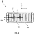
- FIG. 2 is a plan view of drip irrigation dripper 1 illustrated in FIG. 1 .
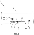
- FIG. 3 is a schematic sectional view illustrating drip watering tube 2 as a drip irrigation device according to Embodiment 1.
- drip watering tube 2 in Embodiment 1 includes substantially cylindrical elongated tube main body 3 as a flow pipe for flowing the irrigation liquid, and drip irrigation dripper 1 disposed inside tube main body 3.
- drip irrigation dripper 1 is disposed on inner peripheral surface 31 of tube main body 3 at a position corresponding to ejection port 33 for irrigation liquid which extends through inner peripheral surface 31 and outer peripheral surface 32 of tube main body 3 in such a manner as to cover ejection port 33. Drip irrigation dripper 1 controls the ejection amount of the irrigation liquid from corresponding ejection port 33 per unit time.
- FIG. 3 illustrates one drip irrigation dripper 1 and one ejection port 33 for convenience's sake, a plurality of drip irrigation drippers 1 and ejection ports 33 are disposed at predetermined intervals along the length of tube main body 3 in practical use.
- the left and right sides of the channel inside tube main body 3 correspond to the upstream (water source) side and the downstream side, respectively.
- drip irrigation dripper (drip irrigation dripper main body) 1 is formed into a shape of substantially cuboid plate in appearance elongated in the longitudinal direction of tube main body 3.
- the approximate contour of drip irrigation dripper 1 is composed of bottom surface 11, top surface 12 opposite to bottom surface 11, and side surface 13 connecting bottom surface 11 to top surface 12.
- the materials for drip irrigation dripper 1 and tube main body 3 are not particularly limited.
- the material for drip irrigation dripper 1 is a resin such as polypropylene
- the material for tube main body 3 is a resin such as polyethylene having a melting point lower than that of drip irrigation dripper 1.
- the method of manufacturing tube main body 3 is not particularly limited, either.
- tube main body 3 may be formed by extrusion molding.
- Drip irrigation dripper 1 is joined to inner peripheral surface 31 of tube main body 3 at bottom surface 11.
- joining of drip irrigation dripper 1 formed by extrusion molding to inner peripheral surface 31 of tube main body 3 may be designed to be completed concurrently with the curing of tube main body 3 after disposing drip irrigation dripper 1 on inner peripheral surface 31 of uncured tube main body 3.
- inflow part 5 that allows the irrigation liquid in tube main body 3 to flow into channel 4 inside drip irrigation dripper 1 is disposed on top surface 12 of drip irrigation dripper 1.
- ejection amount control part 6 that controls the ejection amount of the irrigation liquid to be ejected from ejection port 33 through channel 4 is disposed at a position on the downstream side of inflow part 5 in channel 4.
- channel 4 either may be formed only by drip irrigation dripper 1, or may be formed by drip irrigation dripper 1 and inner peripheral surface 31 of tube main body 3.
- inflow part 5 may be provided with a single or a plurality of inflow ports bored on top surface 12 to allow communication between the outside of drip irrigation dripper 1 (channel inside tube main body 3) and channel 4.
- ejection amount control part 6 may have a pressure reduction channel part for forming a pressure reduction channel (a part of channel 4) that allows the irrigation liquid having flowed from inflow part 5 to flow toward ejection port 33 while reducing the pressure of the irrigation liquid. Furthermore, ejection amount control part 6 may have a diaphragm part that is disposed to be exposed to the liquid pressure of the irrigation liquid and is formed to be deformed toward ejection port 33 larger as the liquid pressure becomes larger so as to increase the shielding amount of ejection port 33 or channel 4 immediately before ejection port 33.
- PTL 1 discloses a configuration to allow irrigation water to flow from a housing inlet (inflow part) into a restriction channel (pressure reduction channel) for pressure reduction and allow the irrigation water of which pressure was reduced to flow out of a housing outlet toward an ejection port, and to control the inflow and the outflow with a film (diaphragm part).
- Japanese Patent Application No. 2012-118551 filed prior to the present application discloses a drip irrigation dripper that includes an inflow part, a pressure reduction channel part and a diaphragm part, and that is formed integrally of a resin material.
- 2012-216575 discloses a drip irrigation dripper that has an inflow control part (inflow part), a pressure reduction channel part and a flow rate control part, and that is formed integrally of a resin material. These disclosed techniques may be employed as means for embodying channel 4, inflow part 5, and ejection amount control part 6 of drip irrigation dripper 1 of the present embodiment.
- first groove part 121 is formed in top surface 12 to extend from a first end (left end in FIG. 2 ) toward a second end (right end in FIG. 2 ) in the longitudinal direction (Y direction) of top surface 12.
- first end in the longitudinal direction of top surface 12 is an end portion on the upstream side in the flow direction of the irrigation liquid in tube main body 3.
- the end portion on the second end side in the longitudinal direction of first groove part 121 is positioned closer to the first end side than the center portion to the first end side in the longitudinal direction of top surface 12.
- first groove part 121 is formed into such a wedge shape (in other words, triangle pyramid shape) that the groove width (dimension in X direction) and the groove depth (dimension in Z direction) are gradually decreased toward the second end in the longitudinal direction of top surface 12.
- first groove part 121 is formed such that the groove depth is gradually increased toward the center portion in the groove width direction.
- First groove part 121 has a shape of isosceles triangle in a plan view ( FIG. 2 ).
- filter structure 123 for inhibiting foreign matters from entering channel 4 is formed on top surface 12 including first groove part 121.
- the filter structure 123 has a plurality of convex parts 1231.
- the plurality of convex parts 1231 are elongated in the width direction (X direction) of top surface 12, and has a predetermined height (dimension in Z direction).
- the convex parts 1231 are disposed at predetermined intervals in the longitudinal direction of top surface 12.
- drip irrigation dripper 1 of Embodiment 1 a part of the irrigation liquid flowing in tube main body 3 flows into channel 4 of drip irrigation dripper 1 from inflow part 5, and the ejection amount thereof is controlled by ejection amount control part 6, so that the irrigation liquid is ejected from ejection port 33 toward the outside of drip watering tube 2.
- the irrigation liquid not flowing into drip irrigation dripper 1 passes over top surface 12 of drip irrigation dripper 1 to flow toward the downstream in tube main body 3.
- the resistance by drip irrigation dripper 1 to the irrigation liquid passing over first groove part 121 is effectively reduced by first groove part 121.
- the flow is gathered toward the center portion in the width direction of first groove part 121 to allow the flow to be straightened along the central portion, and thus high rectilinearity toward the downstream in tube main body 3 can be performed.
- pressure drop of the irrigation liquid caused by drip irrigation dripper 1 is effectively reduced by first groove part 121.
- the irrigation liquid can be allowed to flow toward the downstream in tube main body 3 while maintaining the liquid pressure, thereby securing the opportunity for drip irrigation dripper 1 on the downstream side to eject the irrigation liquid.
- the irrigation liquid in tube main body 3 can be allowed to flow efficiently up to the downstream side by alleviating the pressure drop caused by drip irrigation dripper 1. Therefore, disposing a plurality of drip irrigation drippers 1 according to the present invention along tube main body 3 makes it possible to properly perform long-distance watering.
- the irrigation liquid can pass over first groove part 121 at high speed, the irrigation liquid can flush filter structure 123 on first groove part 121. Therefore, it is possible to reduce a deterioration in the performance of drip irrigation dripper 1.
- a portion in side surface 13 in a predetermined range closer to top surface 12 may be formed into curved surface 131, to thereby further reduce pressure drop.
- drip irrigation dripper 1 according to Embodiment 2 of the present invention will be described with reference to FIGS. 4 to 7 .
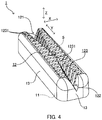
- FIG. 4 is a schematic perspective bird's eye view illustrating a drip irrigation dripper according to Embodiment 2 of the present invention.
- FIG. 5 is a plan view of the drip irrigation dripper illustrated in FIG. 4 .
- FIG. 6 is a schematic sectional view of a drip watering tube for the drip irrigation dripper according to Embodiment 2 of the present invention.
- drip irrigation dripper 1 of Embodiment 2 includes second groove part 122 formed in top surface 12, in addition to the configuration of drip irrigation dripper 1 of Embodiment 1.
- second groove part 122 extends from a second end (right end in FIG. 5 ) toward a first end (left end in FIG. 5 ) in the longitudinal direction (Y direction) of top surface 12.
- the end portion on the first end side in the longitudinal direction of second groove part 122 is positioned closer to the second end side in the longitudinal direction than the center portion in the longitudinal direction of top surface 12 to the second end side.
- first groove part 121 is formed from the first end toward the second end in the longitudinal direction of top surface 12.
- second groove part 122 is formed into such a wedge shape (in other words, triangle pyramid shape) that the groove width (dimension in X direction) and the groove depth (dimension in Z direction) are gradually decreased toward the first end in the longitudinal direction of top surface 12.
- second groove part 122 is formed such that the groove depth is gradually increased toward the center portion in the groove width direction.
- Second groove part 122 has a shape of isosceles triangle in a plan view ( FIG. 5 ). It is noted that the shape of second groove part 122 may be congruent with the shape of first groove part 121. In addition, as illustrated in FIG. 5 , the center line of second groove part 122 may be disposed collinearly with the center line (broken straight line) of first groove part 121.
- second groove part 122 instead of first groove part 121, can perform the function of enhancing the rectilinearity of the irrigation liquid.
- drip irrigation dripper 1 of Embodiment 2 has the configuration capable of absorbing the manufacturing error, the manufacturing easiness and the yield rate can be enhanced.
- drip irrigation dripper 1 according to Embodiment 3 of the present invention will be described with reference to FIGS. 8 to 10 .
- FIG. 8 is a schematic perspective bird's eye view illustrating a drip irrigation dripper according to Embodiment 3 of the present invention.
- FIG. 9 is a plan view of the drip irrigation dripper illustrated in FIG. 8 .
- FIG. 10 is an explanatory drawing of the operation and effect of the drip irrigation dripper according to Embodiment 3.
- drip irrigation dripper 1 according to Embodiment 3 and drip irrigation dripper 1 according to Embodiment 1 differ in that the center line (see broken straight line in FIG. 9 ) of first groove part 121 is inclined relative to the longitudinal direction (Y direction) of top surface 12.
- first groove part 121 generates a flow of the irrigation liquid that is inclined relative to the longitudinal direction of tube main body 3, thereby allowing the flow to be a spiral vortex flow to move toward the downstream in tube main body 3.
- Such a spiral vertex flow is not easily resisted by drip irrigation dripper 1 compared with a linear flow, and thus pressure drop can be reduced further effectively.
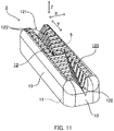
- FIG. 11 is a schematic perspective bird's eye view illustrating a drip irrigation dripper according to a modification of Embodiment 3.
- FIG. 12 is a plan view of the drip irrigation dripper illustrated in FIG. 11 .
- first groove part 121 and second groove part 122 may be formed such that the center lines thereof are parallel to each other.
- first groove parts 121 and second groove parts 122 of a plurality of drip irrigation drippers inside tube main body 3 can sustain the spiral vortex flow over a longer distance, and thus the pressure drop can be reduced further effectively.
- inflow part 5 may be formed on first groove part 121 or second groove part 122.
- Filter structure 123 on first groove part 121 and second groove part 122 may be provided as necessary.
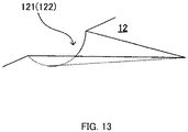
- FIG. 13 is a perspective view illustrating the main portion of another embodiment of the present invention. As illustrated in FIG. 13 , first groove part 121 and second groove part 122 may be formed into a substantially semi-conical shape.
- the present invention it is possible to easily provide a dripper in which dropping of liquid is performed at a suitable rate using the pressure of the liquid to be dropped. Therefore, it is expected that the dripper is broadly applied in the technical fields of drip irrigation, an endurance test and the like where dropping for a long period of time is desired, and that the further development in the technical fields is achieved.
Landscapes
- Life Sciences & Earth Sciences (AREA)
- Soil Sciences (AREA)
- Engineering & Computer Science (AREA)
- Water Supply & Treatment (AREA)
- Environmental Sciences (AREA)
- Nozzles (AREA)
- Infusion, Injection, And Reservoir Apparatuses (AREA)
Claims (13)
- Goutteur d'irrigation au goutte-à-goutte (1) à disposer sur une surface périphérique interne (31) d'un tuyau d'écoulement allongé configuré pour permettre l'écoulement à travers lui d'un liquide d'irrigation en une position correspondant à un orifice d'éjection (33) pour le liquide d'irrigation, l'orifice d'éjection (33) s'étendant à travers la surface périphérique intérieure (31) et une surface périphérique extérieure du tuyau d'écoulement, le goutteur d'irrigation au goutte-à-goutte (1) étant configuré pour réaliser une irrigation au goutte-à-goutte en éjectant le liquide d'irrigation à partir de l'orifice d'éjection (33),
le goutteur d'irrigation au goutte-à-goutte (1) étant façonné en forme de plaque allongée dans une direction longitudinale du tuyau d'écoulement pour présenter une surface de fond (11) à joindre à la surface périphérique intérieure (31) du tuyau d'écoulement et une surface de dessus (12), opposée à la surface de fond (11), le goutteur d'irrigation au goutte-à-goutte (1) comprenant :une partie de débit entrant (5) disposée dans la surface de dessus (12) et destinée à permettre l'écoulement du liquide d'écoulement dans le tuyau d'écoulement vers un canal (4) du corps principal du goutteur d'irrigation au goutte-à-goutte (1), etune partie de contrôle de quantité d'éjection (6) disposée en une position sur un côté aval de la partie de débit entrant (5) dans le canal (4) du corps principal du goutteur d'irrigation au goutte-à-goutte (1) afin de contrôler une quantité d'éjection du liquide d'irrigation éjecté à partir de l'orifice d'éjection (33) à travers le canal (4), etune première partie de rainure (121) formée dans la surface de dessus (12), la première partie de rainure (121) s'étendant d'une première extrémité vers une seconde extrémité de la surface de dessus dans la direction longitudinale,caractérisé en ce quela première partie de rainure (121) est façonnée sous une forme telle qu'une largeur de rainure et une profondeur de rainure sont diminuées progressivement vers la seconde extrémité. - Goutteur d'irrigation au goutte-à-goutte (1) selon la revendication 1, dans lequel la première partie de rainure (121) est façonnée en forme de cale.
- Goutteur d'irrigation au goutte-à-goutte (1) selon la revendication 2, dans lequel la première partie de rainure (121) est façonnée sous une forme telle qu'une profondeur de rainure est augmentée progressivement vers une portion centrale dans une direction de largeur de rainure.
- Goutteur d'irrigation au goutte-à-goutte (1) selon la revendication 3, dans lequel la première partie de rainure (121) est façonnée sous une forme telle qu'une ligne centrale dans la direction de largeur de rainure est inclinée par rapport à la direction longitudinale.
- Goutteur d'irrigation au goutte-à-goutte (1) selon la revendication 1, dans lequel une structure de filtre destinée à empêcher l'entrée de corps étrangers dans le canal (4) est façonnée dans la première partie de rainure (121).
- Goutteur d'irrigation au goutte-à-goutte (1) selon l'une quelconque des revendications 1 à 5, comprenant en outre : une seconde partie de rainure (122) façonnée dans la surface de dessus (12), la seconde partie de rainure (122) s'étendant d'une seconde extrémité vers une première extrémité de la surface de dessus (12) dans la direction longitudinale, dans lequel
la seconde partie de rainure (122) est façonnée sous une forme telle qu'une largeur de rainure et une profondeur de rainure sont diminuées progressivement vers la première extrémité. - Goutteur d'irrigation au goutte-à-goutte (1) selon la revendication 6, dans lequel la seconde partie de rainure (122) est façonnée en forme de cale.
- Goutteur d'irrigation au goutte-à-goutte (1) selon la revendication 7, dans lequel la seconde partie de rainure (122) est façonnée sous une forme telle que la profondeur de rainure est augmentée progressivement vers une portion centrale dans une direction de largeur de rainure.
- Goutteur d'irrigation au goutte-à-goutte (1) selon la revendication 8, dans lequel la seconde partie de rainure (122) est façonnée sous une forme telle qu'une ligne centrale dans la direction de largeur de rainure est inclinée par rapport à la direction longitudinale.
- Goutteur d'irrigation au goutte-à-goutte (1) selon la revendication 4, comprenant en outre : une seconde partie de rainure (122) façonnée dans la surface de dessus (12), la seconde partie de rainure (122) s'étendant d'une seconde extrémité vers une première extrémité de la surface de dessus (12) dans la direction longitudinale, dans lequel
la seconde partie de rainure (122) est façonnée sous une forme telle qu'une largeur de rainure et une profondeur de rainure sont diminuées progressivement vers la première extrémité, et est façonnée sous une forme telle qu'une ligne centrale dans la direction de largeur de rainure est parallèle à la ligne centrale de la première partie de rainure (121). - Goutteur d'irrigation au goutte-à-goutte (1) selon la revendication 6, dans lequel une structure de filtre destinée à empêcher l'entrée de corps étrangers dans le canal (4) est façonnée dans la seconde partie de rainure (122).
- Dispositif d'irrigation au goutte-à-goutte comprenant :un tuyau d'écoulement allongé configuré pour permettre l'écoulement à travers lui d'un liquide d'irrigation, etle goutteur d'irrigation au goutte-à-goutte (1) selon l'une quelconque des revendications 1 à 11, disposé en une position correspondant à un orifice d'éjection (33) pour le liquide d'irrigation, l'orifice d'éjection (33) s'étendant à travers la surface périphérique intérieure et la surface périphérique extérieure du tuyau d'écoulement.
- Goutteur d'irrigation au goutte-à-goutte selon la revendication 12, dans lequel
le goutteur d'irrigation au goutte-à-goutte (1) est le goutteur d'irrigation au goutte-à-goutte (1) selon l'une quelconque des revendications 1 à 5, et
la première partie de rainure (121) est disposée dans la surface de dessus (12) sur un côté d'extrémité amont dans une direction d'écoulement du liquide d'irrigation dans le tuyau d'écoulement.
Applications Claiming Priority (2)
| Application Number | Priority Date | Filing Date | Title |
|---|---|---|---|
| JP2012278353 | 2012-12-20 | ||
| PCT/JP2013/007480 WO2014097638A1 (fr) | 2012-12-20 | 2013-12-19 | Goutteur d'irrigation par goutte-à-goutte et dispositif d'irrigation par goutte-à-goutte équipé de ce dernier |
Publications (3)
| Publication Number | Publication Date |
|---|---|
| EP2936974A1 EP2936974A1 (fr) | 2015-10-28 |
| EP2936974A4 EP2936974A4 (fr) | 2016-07-13 |
| EP2936974B1 true EP2936974B1 (fr) | 2018-04-11 |
Family
ID=50977997
Family Applications (1)
| Application Number | Title | Priority Date | Filing Date |
|---|---|---|---|
| EP13864026.3A Not-in-force EP2936974B1 (fr) | 2012-12-20 | 2013-12-19 | Goutteur d'irrigation par goutte-à-goutte et dispositif d'irrigation par goutte-à-goutte équipé de ce dernier |
Country Status (7)
| Country | Link |
|---|---|
| US (1) | US9883639B2 (fr) |
| EP (1) | EP2936974B1 (fr) |
| JP (1) | JP6251186B2 (fr) |
| CN (1) | CN104853593B (fr) |
| ES (1) | ES2672197T3 (fr) |
| IL (1) | IL239547B (fr) |
| WO (1) | WO2014097638A1 (fr) |
Families Citing this family (7)
| Publication number | Priority date | Publication date | Assignee | Title |
|---|---|---|---|---|
| JP6630472B2 (ja) * | 2014-10-07 | 2020-01-15 | 株式会社エンプラス | エミッタおよび点滴灌漑用チューブ |
| WO2016136695A1 (fr) * | 2015-02-25 | 2016-09-01 | 株式会社エンプラス | Goutteur et tube d'irrigation goutte à goutte |
| JP6532763B2 (ja) | 2015-02-25 | 2019-06-19 | 株式会社エンプラス | エミッタおよび点滴灌漑用チューブ |
| JP6639212B2 (ja) * | 2015-12-09 | 2020-02-05 | 株式会社エンプラス | エミッタおよび点滴灌漑用チューブ |
| JP2019054758A (ja) * | 2017-09-21 | 2019-04-11 | 株式会社エンプラス | エミッタおよび点滴灌漑用チューブ |
| CN109429662B (zh) * | 2018-11-27 | 2024-01-19 | 长安大学 | 一种具有水肥耦合功能的滴灌系统 |
| CN118901557B (zh) * | 2024-09-20 | 2025-03-21 | 河南民荣建筑工程有限公司 | 农田滴灌装置及在水利灌溉中的应用 |
Family Cites Families (17)
| Publication number | Priority date | Publication date | Assignee | Title |
|---|---|---|---|---|
| US3981452A (en) * | 1975-02-10 | 1976-09-21 | Gershon Eckstein | Irrigation pipes with dripper units and method of its manufacture |
| US3993248A (en) * | 1975-08-13 | 1976-11-23 | Harmony Emitter Company, Inc. | Fluid flow regulator |
| CH678476A5 (fr) * | 1986-04-11 | 1991-09-30 | Maillefer Sa | |
| US4869432A (en) * | 1987-12-04 | 1989-09-26 | Christy Mark H | Elastomeric flow control pin for irrigation systems |
| US5400973A (en) * | 1993-07-30 | 1995-03-28 | Cohen; Amir | Pressure responsive regulated flow restrictor useful for drip irrigation |
| US5615838A (en) * | 1995-03-10 | 1997-04-01 | Drip Irrigation Systems, Ltd. | In-line retention drip emitter |
| US6116523A (en) * | 1997-05-06 | 2000-09-12 | T-Systems International, Inc. | Pressure-compensating drip irrigation hose and method for its manufacture |
| IL121967A (en) | 1997-10-14 | 2001-06-14 | Hydro Plan Eng Ltd | Irrigation output unit |
| IL122777A (en) * | 1997-12-28 | 2003-12-10 | Amir Cohen | Valve controlled drip irrigation lines |
| US6173526B1 (en) * | 1998-02-10 | 2001-01-16 | Angelo L. Mazzei | Beneficiation of soil with dissolved oxygen for growing crops |
| US8302887B2 (en) * | 2005-03-31 | 2012-11-06 | Rain Bird Corporation | Drip emitter |
| JP4998261B2 (ja) | 2005-06-06 | 2012-08-15 | 三菱瓦斯化学株式会社 | レジスト用化合物およびレジスト組成物 |
| CN100498807C (zh) * | 2007-02-09 | 2009-06-10 | 中国农业大学 | 一种抗堵塞滴灌灌水器设计方法 |
| US7988076B2 (en) * | 2008-10-20 | 2011-08-02 | D.R.T.S. Enterprises Ltd. | Non-clogging non-pressure compensated drip emitter |
| CN201938158U (zh) * | 2011-01-11 | 2011-08-24 | 喀什宏邦节水灌溉设备工程有限公司 | 边缝式毛细管稳流滴灌带 |
| JP2012216575A (ja) | 2011-03-31 | 2012-11-08 | Nec Toppan Circuit Solutions Inc | 部品内蔵印刷配線板及びその製造方法 |
| US9485923B2 (en) * | 2012-03-26 | 2016-11-08 | Rain Bird Corporation | Elastomeric emitter and methods relating to same |
-
2013
- 2013-12-19 EP EP13864026.3A patent/EP2936974B1/fr not_active Not-in-force
- 2013-12-19 CN CN201380065361.8A patent/CN104853593B/zh not_active Expired - Fee Related
- 2013-12-19 ES ES13864026.3T patent/ES2672197T3/es active Active
- 2013-12-19 WO PCT/JP2013/007480 patent/WO2014097638A1/fr not_active Ceased
- 2013-12-19 US US14/653,358 patent/US9883639B2/en not_active Expired - Fee Related
- 2013-12-19 JP JP2014552945A patent/JP6251186B2/ja not_active Expired - Fee Related
-
2015
- 2015-06-18 IL IL239547A patent/IL239547B/en active IP Right Grant
Non-Patent Citations (1)
| Title |
|---|
| None * |
Also Published As
| Publication number | Publication date |
|---|---|
| EP2936974A4 (fr) | 2016-07-13 |
| IL239547A0 (en) | 2015-08-31 |
| US9883639B2 (en) | 2018-02-06 |
| EP2936974A1 (fr) | 2015-10-28 |
| JPWO2014097638A1 (ja) | 2017-01-12 |
| IL239547B (en) | 2020-08-31 |
| WO2014097638A1 (fr) | 2014-06-26 |
| ES2672197T3 (es) | 2018-06-13 |
| US20160183482A1 (en) | 2016-06-30 |
| CN104853593A (zh) | 2015-08-19 |
| JP6251186B2 (ja) | 2017-12-20 |
| CN104853593B (zh) | 2017-05-17 |
Similar Documents
| Publication | Publication Date | Title |
|---|---|---|
| EP2936974B1 (fr) | Goutteur d'irrigation par goutte-à-goutte et dispositif d'irrigation par goutte-à-goutte équipé de ce dernier | |
| JP6208672B2 (ja) | 点滴灌漑用ドリッパおよび点滴灌漑装置 | |
| JP6180410B2 (ja) | 点滴灌漑用ドリッパおよびこれを備えた点滴灌漑装置 | |
| EP2932824B1 (fr) | Goutteur pour irrigation goutte à goutte et dispositif d'irrigation goutte à goutte équipé de celui-ci | |
| EP3039961B1 (fr) | Goutteur et tube d'irrigation goutte à goutte | |
| ES2982795T3 (es) | Emisor elastomérico y métodos relacionados con el mismo | |
| EP3132678B1 (fr) | Goutteur d'irrigation goutte à goutte et dispositif d'irrigation goutte à goutte le comprenant | |
| EP3085225B1 (fr) | Émetteur et tube d'irrigation au goutte-à-goutte | |
| EP3075233B1 (fr) | Emetteur et tube d'irrigation goutte a goutte | |
| EP2424682A1 (fr) | Émetteur de goutte-a-goutte sans obstruction à pression interne compensée | |
| KR20200011746A (ko) | 감압라이너를 구비한 점적호스 |
Legal Events
| Date | Code | Title | Description |
|---|---|---|---|
| PUAI | Public reference made under article 153(3) epc to a published international application that has entered the european phase |
Free format text: ORIGINAL CODE: 0009012 |
|
| 17P | Request for examination filed |
Effective date: 20150618 |
|
| AK | Designated contracting states |
Kind code of ref document: A1 Designated state(s): AL AT BE BG CH CY CZ DE DK EE ES FI FR GB GR HR HU IE IS IT LI LT LU LV MC MK MT NL NO PL PT RO RS SE SI SK SM TR |
|
| AX | Request for extension of the european patent |
Extension state: BA ME |
|
| DAX | Request for extension of the european patent (deleted) | ||
| A4 | Supplementary search report drawn up and despatched |
Effective date: 20160610 |
|
| RIC1 | Information provided on ipc code assigned before grant |
Ipc: A01G 25/02 20060101AFI20160606BHEP |
|
| 17Q | First examination report despatched |
Effective date: 20170616 |
|
| GRAP | Despatch of communication of intention to grant a patent |
Free format text: ORIGINAL CODE: EPIDOSNIGR1 |
|
| RIC1 | Information provided on ipc code assigned before grant |
Ipc: A01G 25/02 20060101AFI20171123BHEP Ipc: B05B 15/06 20060101ALN20171123BHEP |
|
| INTG | Intention to grant announced |
Effective date: 20171208 |
|
| RIN1 | Information on inventor provided before grant (corrected) |
Inventor name: IWASAKI, MIKE |
|
| GRAS | Grant fee paid |
Free format text: ORIGINAL CODE: EPIDOSNIGR3 |
|
| GRAA | (expected) grant |
Free format text: ORIGINAL CODE: 0009210 |
|
| AK | Designated contracting states |
Kind code of ref document: B1 Designated state(s): AL AT BE BG CH CY CZ DE DK EE ES FI FR GB GR HR HU IE IS IT LI LT LU LV MC MK MT NL NO PL PT RO RS SE SI SK SM TR |
|
| REG | Reference to a national code |
Ref country code: GB Ref legal event code: FG4D |
|
| REG | Reference to a national code |
Ref country code: CH Ref legal event code: EP |
|
| REG | Reference to a national code |
Ref country code: AT Ref legal event code: REF Ref document number: 986981 Country of ref document: AT Kind code of ref document: T Effective date: 20180415 |
|
| REG | Reference to a national code |
Ref country code: IE Ref legal event code: FG4D |
|
| REG | Reference to a national code |
Ref country code: DE Ref legal event code: R096 Ref document number: 602013035905 Country of ref document: DE |
|
| REG | Reference to a national code |
Ref country code: ES Ref legal event code: FG2A Ref document number: 2672197 Country of ref document: ES Kind code of ref document: T3 Effective date: 20180613 |
|
| REG | Reference to a national code |
Ref country code: NL Ref legal event code: FP |
|
| REG | Reference to a national code |
Ref country code: LT Ref legal event code: MG4D |
|
| PG25 | Lapsed in a contracting state [announced via postgrant information from national office to epo] |
Ref country code: NO Free format text: LAPSE BECAUSE OF FAILURE TO SUBMIT A TRANSLATION OF THE DESCRIPTION OR TO PAY THE FEE WITHIN THE PRESCRIBED TIME-LIMIT Effective date: 20180711 Ref country code: BG Free format text: LAPSE BECAUSE OF FAILURE TO SUBMIT A TRANSLATION OF THE DESCRIPTION OR TO PAY THE FEE WITHIN THE PRESCRIBED TIME-LIMIT Effective date: 20180711 Ref country code: SE Free format text: LAPSE BECAUSE OF FAILURE TO SUBMIT A TRANSLATION OF THE DESCRIPTION OR TO PAY THE FEE WITHIN THE PRESCRIBED TIME-LIMIT Effective date: 20180411 Ref country code: AL Free format text: LAPSE BECAUSE OF FAILURE TO SUBMIT A TRANSLATION OF THE DESCRIPTION OR TO PAY THE FEE WITHIN THE PRESCRIBED TIME-LIMIT Effective date: 20180411 Ref country code: FI Free format text: LAPSE BECAUSE OF FAILURE TO SUBMIT A TRANSLATION OF THE DESCRIPTION OR TO PAY THE FEE WITHIN THE PRESCRIBED TIME-LIMIT Effective date: 20180411 Ref country code: LT Free format text: LAPSE BECAUSE OF FAILURE TO SUBMIT A TRANSLATION OF THE DESCRIPTION OR TO PAY THE FEE WITHIN THE PRESCRIBED TIME-LIMIT Effective date: 20180411 Ref country code: PL Free format text: LAPSE BECAUSE OF FAILURE TO SUBMIT A TRANSLATION OF THE DESCRIPTION OR TO PAY THE FEE WITHIN THE PRESCRIBED TIME-LIMIT Effective date: 20180411 |
|
| PG25 | Lapsed in a contracting state [announced via postgrant information from national office to epo] |
Ref country code: GR Free format text: LAPSE BECAUSE OF FAILURE TO SUBMIT A TRANSLATION OF THE DESCRIPTION OR TO PAY THE FEE WITHIN THE PRESCRIBED TIME-LIMIT Effective date: 20180712 Ref country code: HR Free format text: LAPSE BECAUSE OF FAILURE TO SUBMIT A TRANSLATION OF THE DESCRIPTION OR TO PAY THE FEE WITHIN THE PRESCRIBED TIME-LIMIT Effective date: 20180411 Ref country code: LV Free format text: LAPSE BECAUSE OF FAILURE TO SUBMIT A TRANSLATION OF THE DESCRIPTION OR TO PAY THE FEE WITHIN THE PRESCRIBED TIME-LIMIT Effective date: 20180411 Ref country code: RS Free format text: LAPSE BECAUSE OF FAILURE TO SUBMIT A TRANSLATION OF THE DESCRIPTION OR TO PAY THE FEE WITHIN THE PRESCRIBED TIME-LIMIT Effective date: 20180411 |
|
| REG | Reference to a national code |
Ref country code: AT Ref legal event code: MK05 Ref document number: 986981 Country of ref document: AT Kind code of ref document: T Effective date: 20180411 |
|
| PG25 | Lapsed in a contracting state [announced via postgrant information from national office to epo] |
Ref country code: PT Free format text: LAPSE BECAUSE OF FAILURE TO SUBMIT A TRANSLATION OF THE DESCRIPTION OR TO PAY THE FEE WITHIN THE PRESCRIBED TIME-LIMIT Effective date: 20180813 |
|
| REG | Reference to a national code |
Ref country code: DE Ref legal event code: R097 Ref document number: 602013035905 Country of ref document: DE |
|
| PG25 | Lapsed in a contracting state [announced via postgrant information from national office to epo] |
Ref country code: SK Free format text: LAPSE BECAUSE OF FAILURE TO SUBMIT A TRANSLATION OF THE DESCRIPTION OR TO PAY THE FEE WITHIN THE PRESCRIBED TIME-LIMIT Effective date: 20180411 Ref country code: RO Free format text: LAPSE BECAUSE OF FAILURE TO SUBMIT A TRANSLATION OF THE DESCRIPTION OR TO PAY THE FEE WITHIN THE PRESCRIBED TIME-LIMIT Effective date: 20180411 Ref country code: EE Free format text: LAPSE BECAUSE OF FAILURE TO SUBMIT A TRANSLATION OF THE DESCRIPTION OR TO PAY THE FEE WITHIN THE PRESCRIBED TIME-LIMIT Effective date: 20180411 Ref country code: CZ Free format text: LAPSE BECAUSE OF FAILURE TO SUBMIT A TRANSLATION OF THE DESCRIPTION OR TO PAY THE FEE WITHIN THE PRESCRIBED TIME-LIMIT Effective date: 20180411 Ref country code: AT Free format text: LAPSE BECAUSE OF FAILURE TO SUBMIT A TRANSLATION OF THE DESCRIPTION OR TO PAY THE FEE WITHIN THE PRESCRIBED TIME-LIMIT Effective date: 20180411 Ref country code: DK Free format text: LAPSE BECAUSE OF FAILURE TO SUBMIT A TRANSLATION OF THE DESCRIPTION OR TO PAY THE FEE WITHIN THE PRESCRIBED TIME-LIMIT Effective date: 20180411 |
|
| REG | Reference to a national code |
Ref country code: CH Ref legal event code: PK Free format text: BERICHTIGUNGEN |
|
| RIC2 | Information provided on ipc code assigned after grant |
Ipc: A01G 25/02 20060101AFI20171123BHEP Ipc: B05B 15/06 20060101ALN20171123BHEP |
|
| PLBE | No opposition filed within time limit |
Free format text: ORIGINAL CODE: 0009261 |
|
| STAA | Information on the status of an ep patent application or granted ep patent |
Free format text: STATUS: NO OPPOSITION FILED WITHIN TIME LIMIT |
|
| PG25 | Lapsed in a contracting state [announced via postgrant information from national office to epo] |
Ref country code: IT Free format text: LAPSE BECAUSE OF FAILURE TO SUBMIT A TRANSLATION OF THE DESCRIPTION OR TO PAY THE FEE WITHIN THE PRESCRIBED TIME-LIMIT Effective date: 20180411 Ref country code: SM Free format text: LAPSE BECAUSE OF FAILURE TO SUBMIT A TRANSLATION OF THE DESCRIPTION OR TO PAY THE FEE WITHIN THE PRESCRIBED TIME-LIMIT Effective date: 20180411 |
|
| 26N | No opposition filed |
Effective date: 20190114 |
|
| PG25 | Lapsed in a contracting state [announced via postgrant information from national office to epo] |
Ref country code: SI Free format text: LAPSE BECAUSE OF FAILURE TO SUBMIT A TRANSLATION OF THE DESCRIPTION OR TO PAY THE FEE WITHIN THE PRESCRIBED TIME-LIMIT Effective date: 20180411 |
|
| REG | Reference to a national code |
Ref country code: CH Ref legal event code: PL |
|
| GBPC | Gb: european patent ceased through non-payment of renewal fee |
Effective date: 20181219 |
|
| PG25 | Lapsed in a contracting state [announced via postgrant information from national office to epo] |
Ref country code: LU Free format text: LAPSE BECAUSE OF NON-PAYMENT OF DUE FEES Effective date: 20181219 Ref country code: MC Free format text: LAPSE BECAUSE OF FAILURE TO SUBMIT A TRANSLATION OF THE DESCRIPTION OR TO PAY THE FEE WITHIN THE PRESCRIBED TIME-LIMIT Effective date: 20180411 |
|
| REG | Reference to a national code |
Ref country code: IE Ref legal event code: MM4A |
|
| REG | Reference to a national code |
Ref country code: BE Ref legal event code: MM Effective date: 20181231 |
|
| PG25 | Lapsed in a contracting state [announced via postgrant information from national office to epo] |
Ref country code: IE Free format text: LAPSE BECAUSE OF NON-PAYMENT OF DUE FEES Effective date: 20181219 |
|
| PG25 | Lapsed in a contracting state [announced via postgrant information from national office to epo] |
Ref country code: BE Free format text: LAPSE BECAUSE OF NON-PAYMENT OF DUE FEES Effective date: 20181231 |
|
| PG25 | Lapsed in a contracting state [announced via postgrant information from national office to epo] |
Ref country code: GB Free format text: LAPSE BECAUSE OF NON-PAYMENT OF DUE FEES Effective date: 20181219 Ref country code: CH Free format text: LAPSE BECAUSE OF NON-PAYMENT OF DUE FEES Effective date: 20181231 Ref country code: LI Free format text: LAPSE BECAUSE OF NON-PAYMENT OF DUE FEES Effective date: 20181231 |
|
| PG25 | Lapsed in a contracting state [announced via postgrant information from national office to epo] |
Ref country code: MT Free format text: LAPSE BECAUSE OF NON-PAYMENT OF DUE FEES Effective date: 20181219 |
|
| PG25 | Lapsed in a contracting state [announced via postgrant information from national office to epo] |
Ref country code: TR Free format text: LAPSE BECAUSE OF FAILURE TO SUBMIT A TRANSLATION OF THE DESCRIPTION OR TO PAY THE FEE WITHIN THE PRESCRIBED TIME-LIMIT Effective date: 20180411 |
|
| PG25 | Lapsed in a contracting state [announced via postgrant information from national office to epo] |
Ref country code: HU Free format text: LAPSE BECAUSE OF FAILURE TO SUBMIT A TRANSLATION OF THE DESCRIPTION OR TO PAY THE FEE WITHIN THE PRESCRIBED TIME-LIMIT; INVALID AB INITIO Effective date: 20131219 Ref country code: CY Free format text: LAPSE BECAUSE OF FAILURE TO SUBMIT A TRANSLATION OF THE DESCRIPTION OR TO PAY THE FEE WITHIN THE PRESCRIBED TIME-LIMIT Effective date: 20180411 Ref country code: MK Free format text: LAPSE BECAUSE OF NON-PAYMENT OF DUE FEES Effective date: 20180411 |
|
| PG25 | Lapsed in a contracting state [announced via postgrant information from national office to epo] |
Ref country code: IS Free format text: LAPSE BECAUSE OF FAILURE TO SUBMIT A TRANSLATION OF THE DESCRIPTION OR TO PAY THE FEE WITHIN THE PRESCRIBED TIME-LIMIT Effective date: 20180811 |
|
| PGFP | Annual fee paid to national office [announced via postgrant information from national office to epo] |
Ref country code: DE Payment date: 20201211 Year of fee payment: 8 Ref country code: FR Payment date: 20201223 Year of fee payment: 8 |
|
| PGFP | Annual fee paid to national office [announced via postgrant information from national office to epo] |
Ref country code: NL Payment date: 20201221 Year of fee payment: 8 |
|
| PGFP | Annual fee paid to national office [announced via postgrant information from national office to epo] |
Ref country code: ES Payment date: 20210223 Year of fee payment: 8 |
|
| REG | Reference to a national code |
Ref country code: DE Ref legal event code: R119 Ref document number: 602013035905 Country of ref document: DE |
|
| REG | Reference to a national code |
Ref country code: NL Ref legal event code: MM Effective date: 20220101 |
|
| PG25 | Lapsed in a contracting state [announced via postgrant information from national office to epo] |
Ref country code: NL Free format text: LAPSE BECAUSE OF NON-PAYMENT OF DUE FEES Effective date: 20220101 |
|
| PG25 | Lapsed in a contracting state [announced via postgrant information from national office to epo] |
Ref country code: DE Free format text: LAPSE BECAUSE OF NON-PAYMENT OF DUE FEES Effective date: 20220701 |
|
| PG25 | Lapsed in a contracting state [announced via postgrant information from national office to epo] |
Ref country code: FR Free format text: LAPSE BECAUSE OF NON-PAYMENT OF DUE FEES Effective date: 20211231 |
|
| REG | Reference to a national code |
Ref country code: ES Ref legal event code: FD2A Effective date: 20230327 |
|
| PG25 | Lapsed in a contracting state [announced via postgrant information from national office to epo] |
Ref country code: ES Free format text: LAPSE BECAUSE OF NON-PAYMENT OF DUE FEES Effective date: 20211220 |