EP2937122B1 - Spielzeugskateboard - Google Patents
Spielzeugskateboard Download PDFInfo
- Publication number
- EP2937122B1 EP2937122B1 EP14185412.5A EP14185412A EP2937122B1 EP 2937122 B1 EP2937122 B1 EP 2937122B1 EP 14185412 A EP14185412 A EP 14185412A EP 2937122 B1 EP2937122 B1 EP 2937122B1
- Authority
- EP
- European Patent Office
- Prior art keywords
- motor
- processor
- toy
- skateboard
- pair
- Prior art date
- Legal status (The legal status is an assumption and is not a legal conclusion. Google has not performed a legal analysis and makes no representation as to the accuracy of the status listed.)
- Active
Links
Images


















Classifications
-
- A—HUMAN NECESSITIES
- A63—SPORTS; GAMES; AMUSEMENTS
- A63H—TOYS, e.g. TOPS, DOLLS, HOOPS OR BUILDING BLOCKS
- A63H17/00—Toy vehicles, e.g. with self-drive; ; Cranes, winches or the like; Accessories therefor
- A63H17/25—Other wheeled vehicles with moving figures
-
- A—HUMAN NECESSITIES
- A63—SPORTS; GAMES; AMUSEMENTS
- A63C—SKATES; SKIS; ROLLER SKATES; DESIGN OR LAYOUT OF COURTS, RINKS OR THE LIKE
- A63C17/00—Roller skates; Skate-boards
- A63C17/01—Skateboards
-
- A—HUMAN NECESSITIES
- A63—SPORTS; GAMES; AMUSEMENTS
- A63C—SKATES; SKIS; ROLLER SKATES; DESIGN OR LAYOUT OF COURTS, RINKS OR THE LIKE
- A63C17/00—Roller skates; Skate-boards
- A63C17/12—Roller skates; Skate-boards with driving mechanisms
-
- A—HUMAN NECESSITIES
- A63—SPORTS; GAMES; AMUSEMENTS
- A63H—TOYS, e.g. TOPS, DOLLS, HOOPS OR BUILDING BLOCKS
- A63H11/00—Self-movable toy figures
-
- A—HUMAN NECESSITIES
- A63—SPORTS; GAMES; AMUSEMENTS
- A63H—TOYS, e.g. TOPS, DOLLS, HOOPS OR BUILDING BLOCKS
- A63H17/00—Toy vehicles, e.g. with self-drive; ; Cranes, winches or the like; Accessories therefor
-
- A—HUMAN NECESSITIES
- A63—SPORTS; GAMES; AMUSEMENTS
- A63H—TOYS, e.g. TOPS, DOLLS, HOOPS OR BUILDING BLOCKS
- A63H17/00—Toy vehicles, e.g. with self-drive; ; Cranes, winches or the like; Accessories therefor
- A63H17/26—Details; Accessories
-
- A—HUMAN NECESSITIES
- A63—SPORTS; GAMES; AMUSEMENTS
- A63H—TOYS, e.g. TOPS, DOLLS, HOOPS OR BUILDING BLOCKS
- A63H17/00—Toy vehicles, e.g. with self-drive; ; Cranes, winches or the like; Accessories therefor
- A63H17/26—Details; Accessories
- A63H17/262—Chassis; Wheel mountings; Wheels; Axles; Suspensions; Fitting body portions to chassis
-
- A—HUMAN NECESSITIES
- A63—SPORTS; GAMES; AMUSEMENTS
- A63H—TOYS, e.g. TOPS, DOLLS, HOOPS OR BUILDING BLOCKS
- A63H29/00—Drive mechanisms for toys in general
-
- A—HUMAN NECESSITIES
- A63—SPORTS; GAMES; AMUSEMENTS
- A63H—TOYS, e.g. TOPS, DOLLS, HOOPS OR BUILDING BLOCKS
- A63H29/00—Drive mechanisms for toys in general
- A63H29/22—Electric drives
-
- A—HUMAN NECESSITIES
- A63—SPORTS; GAMES; AMUSEMENTS
- A63H—TOYS, e.g. TOPS, DOLLS, HOOPS OR BUILDING BLOCKS
- A63H30/00—Remote-control arrangements specially adapted for toys, e.g. for toy vehicles
- A63H30/02—Electrical arrangements
- A63H30/04—Electrical arrangements using wireless transmission
-
- A—HUMAN NECESSITIES
- A63—SPORTS; GAMES; AMUSEMENTS
- A63H—TOYS, e.g. TOPS, DOLLS, HOOPS OR BUILDING BLOCKS
- A63H33/00—Other toys
- A63H33/30—Imitations of miscellaneous apparatus not otherwise provided for, e.g. telephones, weighing-machines, cash-registers
-
- A—HUMAN NECESSITIES
- A63—SPORTS; GAMES; AMUSEMENTS
- A63H—TOYS, e.g. TOPS, DOLLS, HOOPS OR BUILDING BLOCKS
- A63H33/00—Other toys
- A63H33/42—Toy models or toy scenery not otherwise covered
Definitions
- the present invention relates to a toy skateboard and more particularly to a toy skateboard that includes a removable motorized assembly housing.
- Toy skateboards have been a mainstay in kids toys for a number of years. Toy skateboards are often referred to as finger boards because the user of the toy skateboards uses two of their fingers in operating the toy. A skilled operator of the toy skateboard is capable of replicating skateboarding maneuvers with their hand. These skateboards are extremely popular but have become stagnated in their ability to reach a wider audience since their introduction in the 1990s.
- skateboards range from simple wind-up toy skateboards with mounted figurines, to more advanced radio-controlled toy skateboards with figurines that can be controlled in some degree to portray body movement during skateboarding maneuvers and stunts.
- These motorized skateboards typically include movable battery packs, changeable motor positions, and interchangeable wheel weights to provide different centers of balance for adjusting the performance of various maneuvers.
- some motorized skateboards include a drive mechanism but no steering mechanism. Thus, the skateboard is only maneuverable through body movement of the figurine, as in an actual skateboard, and therefore control of the skateboard may be less than desirable, especially for those of less advanced skill levels.
- a toy skateboard should be provided that offers the enjoyment of both a motorized toy skateboard and a non-motorized toy skateboard with an easy control system that allows for the performance of various maneuvers without having to employ a toy figurine.
- US2009149112 which describes a radio-controled toy skateboard.
- the individual wheels of the rear truck can be controlled separately responsive to radio signals from a remote transmitter for rotation in either direction, while the front wheels rotate freely.
- the rear truck is controllably pivoted with respect to the deck about a kingpin axis that is inclined rearwardly, while the front truck pivots freely about a forwardly inclined kingpin axis.
- a convertible toy skateboard assembly according to claim 1.
- the skateboard assembly includes a deck, a pair of non-motorized truck assemblies and a rear motorized truck assembly.
- the toy skateboard is also convertible; as one of the non-motorized truck assemblies may be easily swapped with a rear motorized truck assembly. This allows for the toy skateboard to either have a pair of non- motorized truck assemblies, which allows the operator to use their fingers to manipulate and move the toy skateboard; or have one non-motorized truck assembly and one motorized truck assembly, which allows the operator to use a remote control unit to control and move the toy skateboard.
- the non-motorized truck assembly as used throughout the various embodiments is typically secured to the lower surface of the deck.
- the non-motorized truck assembly includes a pair of freely rotatable wheels that are positioned transversely to a longitudinal axis of the deck when attached.
- the motorized truck assembly is configured to house at least (i) a battery, (ii) a processor, (iii) a receiver in communication with the processor, and (iv) a pair of motors, each motor separately controlling a rear wheel, of a pair of rear wheels, and wherein the pair of rear wheels are positioned transversely to the longitudinal axis of the deck and behind the pair of front wheels.
- the receiver is configured to receive signals to control the movement of the pair of rear wheels.
- the toy skateboard would therefore include two configurations: a first configuration is defined by having the front non-motorized truck assembly attached to the lower surface towards the front region of the deck and having the rear non-motorized truck assembly removably attached to the lower surface towards the rear region of the deck.
- the upper surface of the deck defines a finger engaging region for a user's fingers to engage and move the toy skateboard.
- a second configuration is defined by removing the rear non-motorized truck assembly and attaching the motorized rear truck assembly to the lower surface towards the rear region of the deck, wherein the movement of the toy skateboard is controllable by the processor in response to signals received by the receiver.
- the toy skateboard may include a circuit in communication with the processor and battery.
- the circuit is configured to change the battery voltage to a fixed voltage to create a more consistent performance from the battery - this may include lowering or boosting the voltage. The change helps increase the enjoyment from the toy skateboard as it no longer seems sluggish as the batteries wear down.
- the remote control unit may include one or more signals to initiate a set of pre- program instructions on the processor to control the pair of rear wheels to perform one or more skateboard maneuvers. These skateboard maneuvers may include, but is not limited to, a skateboard trick, a hill climb, variable speed control, and playback of user recorded input.
- the skateboard in any one of the embodiments may further be defined to have a first motor (from the pair of motors) coupled to a first rear wheel (from the pair of rear wheels) and the processor configured to detect a back electromotive force (“EMF") voltage generated by the rotation of the first motor caused by a manual manipulation of the first rear wheel.
- the processor is further configured to include at least a sleep state and a wake state and is configured to transition between the sleep state and the wake state when the detected back EMF voltage reaches a pre-determined value.
- the processor may further control the pair of motors in accordance with one or more pre-programmed motions resulting in a tactile response when the detected back EMF voltage reaches a pre-determined value.
- the processor may further be configured to detect a second back EMF voltage generated by the rotation of the first motor in an opposite direction due to a manual manipulation of the first rear wheel in an opposite direction.
- the processor is further configured to control the first motor in accordance with one or more of the following pre-programmed motions resulting in a tactile response: (a) move the first rear wheel momentarily, (b) move the first rear wheel continuously, (c) resist motion of the first rear wheel momentarily, (d) resist motion of the first rear wheel continuously, (e) oscillate the first rear wheel momentarily, and (f) oscillate the first rear wheel continuously.
- the motorized rear truck assembly includes a housing defined to include a top profile substantially conforming to a portion of the lower surface of the deck towards the rear region.
- the battery, processor, receiver, and pair of motors are completely positioned within the housing below the top profile of the housing and thus below the lower surface of the deck.
- the housing may also include a front end and a rear end with an intermediate region there-between. This provides space for a battery, defined two have two battery compartments separately positioned in the front end and rear end of the housing, and space for the pair of motors.
- the pair of rear wheels are positioned between the two battery compartments.
- the rear end of the housing containing one of the battery compartments may be angled upwardly to match an angle of the rear end of the deck such that the at least one battery contained in the battery compartment is angled.
- the receiver may be defined as an IR sensor for receiving signals from the remote control unit.
- the IR sensor can be positioned in a window defined in the motorized rear truck assembly towards a front portion thereof and under the lower surface of the deck such that the IR sensor is positioned to receive signals reflected from a surface under the deck of the skateboard.
- the present invention may provide for a toy that may include one or more elements, such as the wheels on a skateboard, an appendage on a toy robot or figure, or a propeller on a toy vehicle. These elements are external to the toy and are moved/controlled separately by a motor.
- the processor is configured to include at least a sleep state and a wake state and is further configured to transition between the two states. Another aspect of the embodiment is that the element is accessible for manipulation by the user, operator, or human which when moved will in turn rotate the motor.
- the processor is configured to detect the back EMF voltage and is further configured to transition between the two states when the detected back EMF voltage reaches a pre-determined value.
- the processor when the detected back EMF voltage reaches the pre-determined value, the processor is further configured to control the motor in accordance with one or more pre-programmed motions, which when executed result in a tactile response.
- a toy vehicle having a low inductance motor powered by a high frequency switched voltage at a frequency high enough to create continuous conduction.
- the vehicle includes an H-bridge circuit configured to control a direction of the motor and an adjustable high frequency DC-DC switch configured to convert a supply voltage to an output voltage, that is lower than the supply voltage, for use by the H-bridge circuit to power the low inductance motor in a forward or reverse direction.
- a processor is provided with instructions configured to change the output voltage from the DC-DC switch from a first voltage to a second voltage.
- the motor may have an inductance of approximately less than 500 uH and more preferably of about 140uH.
- the DC- DC switch may be operating at a frequency greater than 250kHz and more preferably at about 1000kHz or higher.
- the DC-DC switch may be changed digitally.
- the output voltage from the DC-DC switch may be selected by a voltage divider, having a first resistor value and a second resistor value selected by the instructions from the processor such that the output voltage from the DC- DC switch can define a first output voltage and a second output voltage.
- the DC-DC switch can be further configured to define a third output voltage.
- the second resistor value may be selected from a pair of resistors, defined separately to create the first output voltage and the second output voltage respectively and defined in series to create the third output voltage.
- the processor further includes instructions to the H-bridge circuit to only control the direction of the motor.
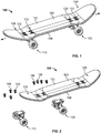
- the toy skateboard 100 includes a deck 102 with an upper surface 103 and a lower surface 104. As illustrated in Figures 1 and 3A , the skateboard 100 includes a front truck assembly 110 secured towards the front end 106 of the deck 102 and either a rear truck assembly 120 or a motorized rear truck assembly 200 secured towards the rear end 108 of the deck 102. The trucks are secured to the deck 102 with fasteners 109 that the operator can easily remove.
- the front and rear non-motorized truck assemblies 110 and 120 may be configured the same as each other, however, the truck assemblies orientation may be reversed.
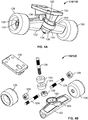
- FIG. 4A through 4C there is illustrated one of the non-motorized truck assemblies (110/120) which includes an axle housing hanger 122 with a pair of axles 124 that extends transversely to the deck 102 and through the hanger 122.
- Wheels 126 are separately mounted at opposing ends of the pair of axles 124 and a secured onto the axles by a nut 128.
- the wheels 126 rotate independently of each other so that the skateboard can negotiate turns without binding.
- the nut 128 may be replaced with a more general retainer that allows the user to replace or swap wheels to customize the skateboard.
- the hanger 122 is attached to a base plate 130, which is secured to the lower surface 104 of the deck 102.
- the base plate 130 includes a pivot cup 132 ( Figure 4C ) which receives a pivot member 134 extending from the hanger 122.
- a king pin 136 is placed in a bore 140 on the base plate and aligned through an opening 142 in the hanger 122 with a king pin nut 138 being secured on the end; and a pair of bushings 144 are positioned on either side of the opening 142 in the hanger 122.
- the deck 102 is relatively small in thickness throughout the length of the board. This permits the deck 102 to be used by an operator as illustrated in Figure 1 without a motor assembly or controlled with a remote control unit when the rear truck assembly 120 is removed and replaced with a motorized rear truck assembly 200. As such, the motorized rear truck assembly 200 is completely self-contained. As found in the prior art, motorized toy skateboards include one or more components in a large constructed deck. These components may be batteries, circuit boards, mechanical links, motors, and/or gears. As illustrated herein, the motorized rear truck assembly 200 is completely self-contained and therefore may be easily removed and exchanged with a non-motorized rear truck assembly 120.
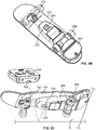
- the skateboard 100 is illustrated with a front truck assembly 110 and a motorized rear truck assembly 200 in accordance with an embodiment of the present invention.
- the skateboard 100 when employed with the motorized rear truck assembly 200 still rests on the surface in a similar configuration as if the skateboard 100 included a non-motorized rear truck assembly 120 (see Figure 6 ) and does so without having to place any components into an oversized deck assembly.
- the skateboard 100 when motorized, maneuverability of the skateboard 100 can be controlled by an operator through a remote control unit 300. Therefore, two complete play patterns are developed. First, using a non-motorized truck assembly 120, the skateboard 100 can be used as a typical fingerboard.
- the non-motorized truck assembly 120 can be removed and replaced with the self-contained motorized truck assembly 200, and then secured to the deck with the same fasteners 109.
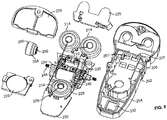
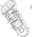
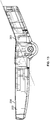
- the motorized rear truck assembly 200 includes a housing 202 that is elongated with an upper surface 204 or upper profile 203 that substantially matches the lower surface 104 of the deck 102 which aids in keeping all of the components substantially below the lower surface of the deck and allows the pair of rear wheels 206 to substantially align along a similar plane as the front wheels 126 when the wheels are resting on a surface.
- a fastening plate 210 is positioned under a portion 205 of the upper surface 204 of the housing 202.
- the portion 205 of the upper surface 204 includes openings 207 that are aligned with threaded openings 209 in the fastening plate 210 and which align with the rearward openings through the deck 102 such that the fasteners 109 can easily secure and release the entire housing 202 by the fastening plate 210, and thus configured to release or secure the rear motor truck assembly 200.
- the housing 202 includes a gear housing compartment 220, a first battery compartment 222 forward of the gear housing compartment 220, and includes a second battery compartment 224 rearward of the gear housing compartment 220.
- the first battery compartment 222 accommodates a first battery 214 in front of the gear housing compartment 220, while the second battery compartment 224 accommodates a pair of batteries 214 rearward of the gear housing compartment 220.
- the first and second battery compartments are accessible from under the housing 202 and secured with battery doors 226.
- the batteries are connected to a circuit board 230 through various wires 228.
- the second battery compartment 224 may include a battery bracket 225 secured over the compartment 224.
- the housing 202 further includes a forward window 232 for the placement of an IR sensor 234 which is in communication with the circuit board 230; its control may be shown and illustrated in the electrical schematic of Figure 14 .
- the IR sensor 234 is positioned to receive signals from the remote control unit 300.
- the circuit board 230 is positioned over the forward window 232 with a PCB cover 240 secured over the circuit board 230 and secured to a forward section of the housing 202. Since all of the components are positioned within the housing and below the lower surface of the deck, the IR sensor 234 is positioned to receive signals from the remote control unit 205 that are bounced from a surface S. In addition, the IR transmitter 305 from the remote control unit 300 is angled downwardly to help in ensuring the signal is sent downwardly towards the surface.
- the gear housing compartment 220 holds a pair of rotary motors 240 separately driving each of the rear wheels 206.
- Each motor 240 includes a drive gear 242 which is meshed to a gear reducer 244 and which is further meshed to a wheel axle gear 246 that is capable of freely spinning on a rear axle 248.
- the rearaxle 248 extends through the housing 202 transversely to the deck 102.
- a pin 250 is employed to rotatably secure the gear reducer 244 to the gear hosing compartment 220.
- the wheel axle gear 246 further includes an end key 252 with an external profile 254 that matches an internal profile 256 positioned on a wheel hub 258.
- a tire 260 is positioned over the wheel hub 258 to create the rear wheel 206.
- the gear housing compartment 220 includes a lower gear housing cover 262 that secures the components in place.
- the housing 202 defined for the motorized rear truck assembly 200 includes an upper surface profile 203 to match the lower surface 104 of the deck 102, as such the housing includes a rearward portion of the second battery compartment 224 that is angled from a horizontal at an angle between 10 and 45 degrees and more particularly at about 22 degrees to match the upturn angle in the rear end 108 of the deck.
- the remote controlled battery powered skateboard is defined as a fingerboard toy skateboard approximately 4 inches long.
- the motors may be small 6mm diameter by 11mm long cylinder motors. Each motor independently controls one rear wheel.
- a high efficiency gear reduction provides a drive speed near 1 meter per second.
- the circuit board receives power from the battery, receives infrared signals from the remote control device, and commands the motors using a processor, DC-DC switch, H-Bridges and software.
- Various play patterns and accessories in the field demand various attributes in order for the toy motorized skateboard to operate properly.
- Various maneuvering capabilities would include the ability to drive straight forward or reverse, turn wide in any four directions, spin left or right, and climb hills starting from a stop position at the base of the hill and from a moving position.
- Consistent repeatable performance will be critical to the user. Typical battery powered products move faster when the batteries are full and slower when the batteries are nearly depleted. This would make practicing tricks more difficult as the user would need to adjust their timing for the current battery level. Additionally, some maneuvers may not be possible at lower battery levels. To eliminate this issue, a constant voltage is generated and supplied to the motors.
- Boost circuits are used to power logic circuits that require a narrow range of voltage to operate. In this application where motor current is relatively low, it is possible to use low cost boost circuits to power two motors. Buck circuits, known to those skilled in the art, may also be employed to provide a consistent and repeatable motor voltage. The choice of buck versus boost circuit depends on whether the motor supply voltage is required to be higher or lower than the battery voltage, which depends on the specific requirements of the embodiment. Either choice of converter type falls within the scope and spirit of the present invention.
- the remote for the toy skateboard will have the usual forward/reverse and right/left controls.
- the remote employs "tank" control, with left controls to control the left propulsion and right controls to control the right propulsion.
- additional "Trick” buttons are added.
- a Trick button sends a single trick command to the toy skateboard. In one embodiment this trick is a simple 180 degree wide turn. In another embodiment the trick is something more complex. Once the trick command is received user controls are disabled. In another embodiment, user controls are allowed to let the user perform a half of a trick followed by their own move if their timing is good. Embodiments disallowing trick termination may be better for younger users. In another embodiment, holding the trick Play button causes the trick to be repeated. In a further embodiment, the remote has a record button.
- every button pressed by the user is simultaneously transmitted and recorded until the record button is pressed again.
- the recorded moves are transmitted to the toy skateboard, performing a custom user generated trick maneuver.
- the toy skateboard 100 is not employed with an on/off switch.
- the operator can push or roll the toy skateboard 100 forward while on a supporting surface.
- This "Turn ON" feature simplifies use, feels more realistic for kids, and reduces cost.
- the toy skateboard 100 immediately performs an easily recognizable pre-programmed movement pattern to indicate that it is ON.
- the pattern is to drive forward for a predetermined amount of time.
- the skateboard 100 turns right, then left several times.
- the ON Pattern can be initiated immediately upon detection.
- the ON Pattern is delayed until the user stops rolling the toy.
- the delay improves the recognition of a successful ON, and is more visually appealing.
- the motors can are pulsed in a pattern to create a haptic response that the user can feel.
- detection of a forward roll is achieved by connecting one of the two motor 240 leads to a processor 406 input.
- the wheels turn, causing motor 240 to generate a back EMF voltage.
- the back EMF voltage generated is a function of the speed the motor 240 is turned and the specific design of the motor 240. As an example, voltages of up to 1.5v are easily generated, and voltages up to 3v are generated with higher roll speeds.
- the processor 406 is configured to wake up from a sleep state.
- a pre-determined value such as 0.7v, or the threshold voltage of an input pin of a processor 406 or transistor, or a specific voltage read by an analog to digital input
- the processor 406 is configured to wake up from a sleep state.
- the skateboard circuit must is carefully designed to minimize current draw during the sleep state. This Turn ON method eliminates the typical ON button or switch, reducing cost.
- the circuit connects both leads of the motor 240 to two separate processor 406 input pins. In this way, both roll forward and roll reverse are detected by the processor 406. These roll commands are recognized in a sleep state, and at any time.
- the processor 406 monitors the input pins to both leads of the motor 240, when the motors 240 are not commanded to move, thereby, processor 406 detects user roll commands.
- this method is expanded to detect both motors 240 and both motor 240 directions. In this embodiment turning the skateboard is also be detected, and provides additional user input to enhance skateboard control.
- the processor 406 detects roll forward to wake to the ON state, and roll backwards to turn OFF into a sleep state.
- the use of a plurality of controllers 300 to individually operate a plurality of skateboards 100 is incorporated. This is done by the use of channel address bits in the command signal emitted from the controller 300 and received by the skateboard 100.
- transmitters 300 are factory preset with specific channel designators. The channel designators are transmitted with each command by controllers 300 comprising the channel address.
- a skateboard 100 When a skateboard 100 is turned ON, it initially does not know which channel it is intended to respond to. However, it sets its channel address based on the first command it receives. In this way, a user can cause a particular skateboard 100 to respond to a particular controller 300 by ensuring that the first command the skateboard 100 receives after it is turned on comes from the intended controller 300.
- a skateboard 100 may inadvertently receive a first command from an undesired controller, thereby incorrectly setting its channel address.
- the user need only turn off skateboard 100, and then turn on skateboard 100, this time ensuring that it receives its first command from the desired controller 300. This may be repeated as necessary until the appropriate pairing has been achieved.
- the afformentioned technique requires a means of turning off skateboard 100 on demand, and thus, the embodiment provides for a means where the skateboard 100 goes to sleep when it is rolled backwards by the user. Turning OFF additionally increases battery life. Since rolling the skateboard forward is associated with ON, it is intuitive and therefore provided that the opposite would turn the device OFF.
- the turn ON feature's haptic response of the skateboard 100 moving the desired intuitive feedback corresponding to the act of turning OFF.
- a haptic response that does match the action is for the skate board to stop, or resist, motion, and thus is implemented in the preferred embodiment.
- the motors 240 are set into braking mode to accomplish this wherein the motor 240 leads are shorted to one another.
- additional rolling input from the user changes the skateboards performance.
- a roll function of the skateboard 100 is recognized by processor 406 when a roll-forward is detected after the skateboard is ON. This causes the skateboard 100 to toggle between modes. In one example, the skateboard 100 alternates between 100% maximum speed and 50% maximum speed. A reduction in overall skateboard speed allows new types of low speed tricks that are more difficult at higher speeds.
- a processor 406 is used and discussed and may be embodied in a number of different ways.
- the processor406 may be embodied as one or more of various processing means or devices such as a coprocessor, a microprocessor, a controller, a digital signal processor (DSP), a processing element with or without an accompanying DSP, or various other processing devices including integrated circuits such as, for example, an ASIC (application specific integrated circuit), an FPGA (field programmable gate array), a microcontroller unit (MCU), a hardware accelerator, a special-purpose computer chip, or the like.
- the processor 406 may be configured to execute instructions stored in a memory device or otherwise accessible to the processor 406.
- the instructions may be permanent (e.g., firmware) or modifiable (e.g., software) instructions.
- the instructions can be bundled or otherwise associated with other instructions in functional profiles, which can be saved as, e.g., an electronic file on one or more memory device.
- the processor 406 may be configured to execute hard coded functionality.
- the processor 406 may represent an entity (e.g., physically embodied in circuitry) capable of performing operations according to embodiments of the present invention while configured accordingly.
- the processor 406 may be specifically configured hardware for conducting the operations described herein.
- the instructions may specifically configure the processor 406 to perform the algorithms and/or operations described herein when the instructions are executed.
- the processor 406 may include, among other things, a clock or any other type of timer, an arithmetic logic unit (ALU) and logic gates configured to support operation of the processor 406.
- ALU arithmetic logic unit
- Haptics involve tactile feedback provided by a device to a user.
- Low-cost haptic devices tend to provide tactile feedback, in which forces are transmitted to a housing or portion thereof and felt by the user, rather than kinesthetic feedback, in which forces are output directly in the degrees of freedom of motion of the interface device.
- the tactile feedback is typically provided by applying forces, vibrations and/or motions to one or more portions of a user interface device.
- Haptics are sometimes used to enhance remote control devices associated with machines and devices. In such systems, sensors in the slave device are sometimes used to detect forces exerted upon such device.
- the information relating to such forces is communicated to a processor, where the information is used to generate suitable tactile feedback for a user.
- the present invention does not use haptics to enhance the touch experience or to allow the use to feel a virtual object or to simulate reaction forces.
- the present invention creates tactile responses to a user interaction with a device that the user can easily correlate or deduce to an unseen setting or mode of the object. Unlike pulsing a pager in different patterns to provide a tactile response, the present invention provides tactile responses so the user can determine which setting or mode the object is now configured. Another important aspect of one or more embodiments, is that the tactile responses are relayed back to the user through the element or mechanism that the user touched to create the input in the first place.
- the embodiments provided herein use elements, such as wheels and actuated arms that are in communication with a motor.
- the direct interaction by the user with these elements generates a back electromotive force through the motor, which is monitored or detected by the processor.
- the processor when triggered by the generated back electromotive force can access and play-back a pre-recorded motion to the element.
- the user still interacting with the element feels the pre-recorded motion which causes the tactile response.
- the tactile response felt by the user allows the user to determine or deduce the object or toy's setting or mode, as further detailed and explained herein.
- a toy 400 may include one or more elements 402, such as the wheels on a skateboard, an appendage on a toy robot or figure, or a propeller on a toy vehicle. These elements are external to the toy 400 and are moved/controlled separately by a motor 404, whether directly or indirectly moved or physically or non-physically coupled is well within the scope of the various embodiments provided for herein.
- the processor 406 is as described herein, and as such further definition is not warranted.
- the processor is configured to include at least a sleep state and a wake state and is further configured to transition between the two states 408.
- Another aspect of the embodiment is that the element is accessible for manipulation by the user, operator, or human which when moved will in turn rotate the motor. When the user manipulates the element, rotating the motor, the rotation of the motor generates a back electromotive force (herein after "EMF") voltage.
- EMF back electromotive force
- the processor is configured to detect the back EMF voltage 410 and is further configured to transition between the two states when the detected back EMF voltage reaches a pre-determined value.
- the processor when the detected back EMF voltage reaches the pre-determined value 412, the processor is further configured to control the motor in accordance with one or more pre-programmed motions 414, which when executed result in a tactile response.
- the processor when the detected back EMF voltage reaches the pre-determined value, the processor is yet further configured to control the motor in accordance with one or more pre- programmed motions resulting in auditory perception.
- the toy 400 may include a number of elements connected separately to motors. All or some of the illustrated elements (wheel 420, appendage(s) 422, propeller 424, etc.) can be included.
- the processor may yet be further configured to detect a second back EMF voltage generated by the rotation of the motor in an opposite direction due to the manipulation of the element by a human in an opposite direction.
- the processor is configured to control the motor in accordance with one or more of the following pre-programmed motions resulting in a tactile response: (a) move said element momentarily, (b) move said element continuously, (c) resist motion of said element momentarily, (d) resist motion of said element continuously, (e) oscillate said element momentarily, and (f) oscillate said element continuously.
- the pre-programmed motions are selected based on the rotational direction of the motor and based on whether the processor is in the wake state or sleep state. This allows for greater functions and motion responses.
- the processor when either the detectable back EMF voltage reaches a pre-determined value, the processor may be further configured to a delay by a pre-determined time internal prior to the pre-programmed motions resulting in a tactile response.
- the pre-programmed motions resulting in a tactile response may be at less than 100% motor speed. In other aspects, the pre-programmed motions result in a tactile response at variating motor speed.
- the embodiments may also include a second motor configured to cause a motion of a second element of toy and the second element is further accessible for manipulation by a human, which when moved causes a rotation in the motor.
- the processor is further configured to control the second motor and the pre- programmed output is further configured to control both motors and rotate both wheels resulting in a tactile response.
- an electrical circuit can be included to alter the back EMF voltage prior to detection by the processor.
- the electrical circuit may be a transistor, resistor, booster, a combination thereof, or other circuits known in the industry.
- a toy vehicle is provided with an element, a processor, and a motor configured to cause a motion of the element.
- the motion of the element is further accessible for manipulation by a human, which in turn is capable of rotating the motor.
- the processor is configured to detect a back electromotive force ("EMF") voltage that is generated by the rotation of the motor when the element is manipulated by the user.
- EMF back electromotive force
- the processor is further configured to include at least two states and the processor includes a function configured to transition between states when the detected back EMF voltage reaches a pre-determined value.
- the processor is further configured to control the motor in accordance with one or more pre-programmed motions resulting in a tactile response when the detected back EMF voltage reaches a pre-determined value.
- the pre-programmed tactile responses may be turning the motor in a forward or reverse direction or braking the motor.
- the toy may include a second motor configured to cause a motion of a second element and the motion of the second element is accessible for manipulation by a human, which when manipulated in turn rotates the motor.
- the processor is further configured to control the second motor, and wherein the pre-programmed output is further configured to control both motors and rotate both wheels resulting in a tactile response.
- the processor may be further configured to detect a second back EMF voltage generated by the rotation of the motor in an opposite direction due to the manipulation by a human in an opposite direction.
- the processor is further configured to control said motors in accordance with one or more pre- programmed motions resulting in a tactile response, when either of the detectable back EMF voltages reach a pre-determined value.
- the pre-programmed motions resulting in a tactile response may include the following: (a) move one or more of said elements momentarily, (b) move one or more of said elements continuously, (c) resist motion of one or more of said elements momentarily, (d) resist motion of one or more of said elements continuously, (e) oscillate one or more of said elements momentarily, and (f) oscillate one or more of said elements continuously.
- the pre-programmed motions may be selected based on the rotation direction of the motor and based on whether the processor is in the wake state or sleep state.
- the processor is further configured to a delay by a pre-determined time internal prior to the pre- programmed motions resulting in a tactile response.
- a toy vehicle having an element, a processor, and a motor configured to cause a motion of the element and the motion of the element is further accessible for manipulation by a human, which when moved causes a rotation of the motor.
- the processor is configured to detect a back electromotive force (“EMF”) voltage generated by the rotation of the motor due to the manipulation of the element by the user.
- EMF back electromotive force
- the processor is further configured to include at least two of the following states: (a) a lower power state configured to turn the at least one motor off and power the vehicle off; (b) a lower power sleep state configured to turn the at least one motor off and put the processor in a low power sleep state and halt executing code; (c) a wake state configured to power the vehicle on; (d) a wake state configured to bring the processor out of a low power sleep state and begin to executing code; (e) a user controllable drive state configured to control the at least one motor and rotate the at least one wheel; (f) a user controllable drive state configured to control the at least one motor and rotate the at least one wheel at a slower than maximum speed; (g) a user controllable drive state configured to control the at least one motor and rotate the at least one wheel in accordance to a pre-programmed set of instructions and user input from a remote device to cause the vehicle to perform a maneuver; and (h) a non-user autonomous drive state configured to control the at least one motor
- the processor further includes a function configured to transition between states when the detected back EMF voltage reaches a pre-determined value. Furthermore, when the detected back EMF voltage reaches a pre-determined value, the processor is further configured to control the motor in accordance with one or more pre-programmed motions resulting in a tactile response.
- the vehicle may include a second motor configured to cause motion of a second element and the motion of the second element is further accessible for manipulation by a human, which in turn causes rotation of the motor.
- the processor is further configured to control the second motor, and wherein the pre-programmed output is further configured to control both motors and rotate both wheels resulting in a tactile response.
- the processor of the vehicle may be further configured to detect second back EMF voltage generated by the rotation of the second motor due to the manipulation by a human in an opposite direction.
- the processor is further configured to transition between the states when the detected second back EMF voltage reaches a pre- determined value.
- the processor is yet further configured to control the second motor in accordance with one or more pre-programmed motions resulting in a tactile response when the detected second back EMF voltage reaches a pre-determined value, which may be the same or different value set to the first back EMF voltage.
- an embodiment of the present invention may provide for a convertible toy skateboard assembly.
- the skateboard assembly typically includes a deck, a pair of non-motorized truck assemblies and a rear motorized truck assembly.
- the toy skateboard is convertible as one of the non-motorized truck assemblies may be easily swapped with the rear motorized truck assembly. This allows for the toy skateboard to either have a pair of non- motorized truck assemblies, which allows the operator to use their fingers to manipulate and move the toy skateboard; or have one non-motorized truck assembly and a motorized truck assembly, which allows the operator to use a remote control unit to control and move the toy skateboard.
- the non-motorized truck assembly as used throughout the various embodiments is typically secured to the lower surface of the deck.
- the non- motorized truck assembly includes a pair of freely rotatable wheels that are positioned transversely to a longitudinal axis of the deck when attached.
- the motorized truck assembly is configured to house at least (i) a battery, (ii) a processor, (iii) a receiver in communication with the processor, and (iv) a pair of motors, each motor separately controlling a rear wheel, of a pair of rear wheels, and wherein the pair of rear wheels are positioned transversely to the longitudinal axis of the deck and behind the pair of front wheels.
- the receiver is configured to receive signals to control the movement of the pair of rear wheels.
- the toy skateboard would therefore include two configurations: a first configuration is defined by having the front non-motorized truck assembly attached to the lower surface towards the front region of the deck and having the rear non-motorized truck assembly removably attached to the lower surface towards the rear region of the deck.
- the upper surface of the deck defines a finger engaging region for a user's fingers to engage and move the toy skateboard.
- a second configuration is defined by removing the rear non-motorized truck assembly and removably attaching the motorized rear truck assembly to the lower surface towards the rear region of the deck, wherein the movement of the toy skateboard is controllable by the processor in response to signals received by the receiver.
- the toy skateboard may include a circuit in communication with the processor and battery.
- the circuit configured to change the battery voltage to a fixed voltage to define a more consistent performance from the battery. This helps increase the enjoyment from the toy skateboard and it no longer seems sluggish as the batteries wear down.
- the remote control unit may include one or more signals to initiate a set of pre-program instructions on the processor to control the pair of rear wheels to perform one or more skateboard maneuvers. These skateboard maneuvers may include, but is not limited to, a skateboard trick, a hill climb, variable speed control, and playback of user recorded input.
- the skateboard in any one of the embodiment may further be defined to have a first motor (from the pair of motors) coupled to a first rear wheel (from the pair of rear wheels) and the processor is configured to detect a back electromotive force (“EMF") voltage generated by the rotation of the first motor caused by a manual manipulation of the first rear wheel.
- the processor is further configured to include at least a sleep state and a wake state and is configured to transition between the sleep state and the wake state when the detected back EMF voltage reaches a pre-determined value.
- the processor may further control the pair of motors in accordance with one or more pre-programmed motions resulting in a tactile response when the detected back EMF voltage reaches a pre-determined value.
- the processor may further be configured to detect a second back EMF voltage generated by the rotation of the first motor in an opposite direction due to a manual manipulation of the first rear wheel in an opposite direction.
- the processor is further configured to control the first motor in accordance with one or more of the following pre-programmed motions resulting in a tactile response: (a) move the first rear wheel momentarily, (b) move the first rear wheel continuously, (c) resist motion of the first rear wheel momentarily, (d) resist motion of the first rear wheel continuously, (e) oscillate the first rear wheel momentarily, and (f) oscillate the first rear wheel continuously.
- the motorized rear truck assembly includes a housing defined to include a top profile substantially conforming to a portion of the lower surface of the deck towards the rear region.
- the battery, processor, receiver, and pair of motors are completely positioned within the housing below the top profile of the housing and thus below the lower surface of the deck.
- the housing may also include a front end and a rear end with an intermediate region there-between. This provides space for a power source, such as batteries, defined by two battery compartments separately positioned in the front end and rear end of the housing and the pair of motors and the pair of rear wheels being positioned between the two battery compartments.
- the rear end of the housing containing one of the battery compartments may be angled upwardly to match an angle of the rear end of the deck such that the at least one battery contained in the battery compartment is angled.
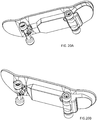
- the placement and number of battery compartments may change, as illustrated in Figures 20A - 20E .
- the receiver may be defined as an IR sensor for receiving signals from the remote control unit.
- the IR sensor can be positioned in a window defined in the motorized rear truck assembly towards a front portion thereof and under the lower surface of the deck such that the IR sensor is positioned to receive signals reflected from a surface under the deck of the skateboard.
- auditory tactile response may be included. For example, spinning a motor creates sound, and the frequency can be changed with the speed such that slow speeds create lower frequencies of sound which can the interpreted as slow, while high speeds create high frequencies of sound which can the interpreted as fast.
- pulsing a motor on and off at a low frequency creates lower frequencies of sound which can the interpreted as slow speeds. Pulsing a motor on and off at a high frequency creates higher frequencies of sound which can the interpreted as fast speed.
- the toy could include multiple responses, such as: Toy response A: While the child is rolling the toy along a surface, the toy wakes from sleep mode and applies power to the wheels in the same direction it was just rolled, while the toy is still in contact with the child's hand and while the toy is still in contact with the surface, resulting in a tactile response of the toy no longer requiring energy to roll but now pulling the child's hand forward; alternately the child may have released the toy after it wakes from sleep but before or during the time power is applied to the wheels, providing a combination of tactile response until the toy is released and an additional visual response as the toy continues to move ahead under its own power.
- Toy response A While the child is rolling the toy along a surface, the toy wakes from sleep mode and applies power to the wheels in the same direction it was just rolled, while the toy is still in contact with the child's hand and while the toy is still in contact with the surface, resulting in a tactile response of the toy no longer requiring energy
- the child may lift the toy off the surface after it wakes from sleep but before or during the time power is applied to the wheels, providing a combination of tactile response until the toy is lifted from the surface and an additional audible response as the toy continues to apply power to the motor creating sound from a combination of the spinning motor, gears, axles, and/or wheels.
- Toy response B Before the child finishes rolling the toy, the toy wakes from sleep mode and pulses power to the wheels in the same direction it was just rolled and in a fashion that resembles a car's engine being revved; or Toy response C: Before the child finishes rolling the toy, the toy wakes from sleep mode and applies a percentage of full power to the wheels in the same direction it was just rolled and in a fashion that resembles a car's engine being revved.
- the toy could include multiple responses, such as: Toy response A: Before the child finishes pulling, the toy applies power to the wheels in the opposite direction it was just pulled; Toy response B: Before the child finishes pulling, the toy pulses power to the wheels in a opposite direction it was just pulled; or Toy response C: Before the child finishes pulling, the toy applies brakes to the wheels. From the user's perception, the user feels that the toy is no longer just rolling backward but is now trying to stop his hand, relaying to the child that the toy is trying to stop and turn OFF. The result of the actions and functions of the vehicle is that the toy goes into a low power sleep mode.
- To Select the Next Mode the child is playing with a toy that is ON and wishes to alter the way it behaves and/or change an action state of the toy.
- the child as an example, rolls the toy forward across the floor.
- the toy could include multiple responses, such as: Toy response: After the child finishes rolling the toy, the toy briefly applies low speed power to the wheels in the same direction it was just rolled. From the user's perception, the user feels that the toy is spinning its wheels slowly, relaying to the child that the toy is now in a low speed drive mode. The result of the actions and functions of the vehicle is that the toy is now set to low speed mode.
- the child is playing with a toy that is ON and wishes to alter the way it behaves and/or change an action state of the toy.
- the child rolls the toy forward across the floor.
- the toy could include multiple responses, such as: Toy response: After the child finishes rolling the toy, the toy briefly applies high speed power to the wheels in the same direction it was just rolled. From the user's perception, the user feels that the toy is spinning its wheels quickly, relaying to the child that the toy is now in a high speed drive mode. The result of the actions and functions of the vehicle is that the toy is now set to high speed mode.
- the vehicle may be able to Directly Set a Mode from the user's interface with the vehicle.
- the child is playing with a toy that is ON and wishes to alter the way it behaves/or change an action state of the toy.
- the child rolls the toy forward across the floor at a slow or fast speed.
- the toy briefly applies power to the wheels in the same direction it was just rolled and at a speed similar to the speed the child rolled the toy.
- the child feels that the toy is spinning its wheels at a specific speed, relaying to the child that the toy is now in a customized speed mode.
- the toy is now set to high speed, slow speed, or specific measured speed mode respectively.
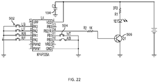
- FIG. 23 there are illustrated electrical schematic and flow chart diagrams to illustrate embodiment of the present invention.
- a remote control unit 500 is shown having various functional buttons 502 and slide switches 504.
- the remote control unit 500 may be fixed to a channel selection or may have a further slide switch to allow the user to switch channels.
- the remote control unit 300 includes a transmitter 506 to send signals or packets of information to the skateboard 100.
- the remote control unit executes WAKE UP (box 510) when any button is pressed.
- the remote control unit may first DETERMINE THE CHANNEL (box 512) and then completes a POLL of the buttons and switches (box 514). A 1 st Packet of Date is transmitted (box 516) to the receiver and then the remote control unit sets the Time and Sleep functions to Zero (box 518). The unit will then WAIT for 25 mSec (box 520), sets TIME to TIME + 1 (box 522) and then POLLS the buttons and Switches (box 524). The remote control unit will then determine IF the buttons or switch have changed (box 526), if no, the remote control unit then determines IF the time internal is equal to 4 (or about 100 mSec) (box 528). If not the remote control unit returns to box 520 to WAIT.
- the remote control unit transmits a Packet of data to the receiver (box 530). After transmission, the remote control unit checks IF All buttons Off then the remote control unit will set Sleep to Sleep + 1, otherwise Sleep is set to Zero (box 532). If Sleep is greater than 10 (about 1 second) (box 534), then the remote control unit will SLEEP (box 436); otherwise the remote control unit returns to box 520 and WAITS.
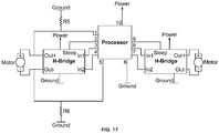
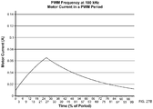
- the speed of a DC motor can be controlled by changing the voltage. Chopping the DC current into “on” and “off' cycles which have an effective lower voltage is one manner in reducing or controlling the speed. This method is also called pulse-width modulation (PWN) and is often controlled by a processor. Since the skateboard in accordance with the present invention incorporates an extremely small DC motor (in the range of 4 mm to 8 mm diameter DC motor), the motor has a low inductance of approximately 140 uH.
- Figures 29A thru 29C show the current waveform in the motor at three different PWM frequencies, 10 kHz, 100 kHz, and 1000 kHz. It can be seen that a 10kHz PWM frequency has not achieved continuous current conduction, which results in current surges that will adversely affect battery run time. It can be see that 100 kHz results in an improvement, but 1000 kHz is approximately required in order to approach acceptable continuous current conduction. Common low cost processers, which are found in low cost toys and vehicles, cannot create the desired 1000 kHz PWM frequency. In reference to Figures 26A - 28 , in one embodiment of the present invention there is employed a novel and unique method of controlling and changing the voltage to extremely small DC motors.
- DC-DC switches often called buck converters
- the embodiment employs a variable output DC-DC switch 600 with the voltage set by a voltage divider.
- the output voltage is typically fixed to one value as defined by the circuits' needs.
- the voltage divider can be changed by the use of processor IO pins and multiple resistors R8 and R9, resulting in three output speeds by connecting R8, R9, or R8 + R9 to the voltage divider (as illustrated in Figures 26A ).
- the resulting voltage supplied to the H-bridge circuits (referred to herein as DRVs) 610 which are in communication with the motors and controlled to direct the direction of the motors at a high frequency.
- a toy vehicle having a low inductance motor powered by a high frequency switched voltage at a frequency high enough to create continuous conduction.
- the vehicle includes an H-bridge circuit configured to control a direction of the motor and an adjustable high frequency DC-DC switch configured to convert a supply voltage to an output voltage, that is lower than the supply voltage, for use by the H-bridge circuit to power the low inductance motor in a forward or reverse direction.
- a processor is provided with instructions configured to change the output voltage from the DC-DC switch from a first voltage to a second voltage.
- the motor may have an inductance of approximately less than 500 uH and more preferably of about 140uH.
- the DC- DC switch may be operating at a frequency greater than 250kHz and more preferably at about 1000kHz or higher.
- the DC-DC switch may be changed digitally.
- the output voltage from the DC-DC switch may be selected by a voltage divider, having a first resistor value and a second resistor value selected by the instructions from the processor such that the output voltage from the DC- DC switch can define a first output voltage and a second output voltage.
- the DC-DC switch can be further configured to define a third output voltage.
- the second resistor value may be selected from a pair of resistors, defined separately to create the first output voltage and the second output voltage respectively and defined in series to create the third output voltage.
- the processor further includes instructions to the H-bridge circuit to only control the direction of the motor.
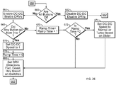
- the processor determines if Sleep is greater than 2 minutes (box 634).
- the processor with Go To Sleep (box 636), if No then the process returns to box 626 to determine if IR Data is received.
- IR Data is started, the processor Receives the IR Packet (box638) and Checks to determine IF the Packet is Good (box 640). If not, the processor returns to box 626. If Yes, the process will set the Channel to Match if the Packet is the 1 st Packet (box 642). If the Packet is not the 1 st Packet the processor Checks to ensure the Packet is from the Correct Channel (box 644).
- Ramp Time may be equated to the user holding a button down or holding a slider in a specific position for a predetermined time. If the Ramp Time is 2 then the processor Sets the DC-DC switch to change the voltage to either Normal Speed or Turbo (high) Speed based on the Slider button input on the remote control (box 674). If the Ramp Time is not 2 (from box 672); or after the DC-DC switch is set (from box 674) the processor will Set the DRV directions based on input from the remote control such that the skateboard is moving Forward, Coasting, Reverse or Turning (box 680).
- the DC-DC switch is able to change the speed of the motor(s) by adjusted voltages by resistor changes to 3 separate speeds, a Start Up Speed, a Normal Speed, and a High Speed; which as noted herein was extremely difficult to obtain using convention chop cycles.
- motors 240 are connected by resistor means to provide increased back EMF detection by processor 406.
- a simplified schematic drawing of an H-bridge 700 is shown in Figure 28 to illustrate the protective flyback diodes D1, D2, D3, D4 integral to such an H-bridge 700.
- diodes D1, D2, D3, D4 are present as the parasitic diode intrinsic to the MOSFET Q1, Q2, Q3, Q4 drivers.
- diodes D1, D2, D3, D4 are explicitly built into the IC to provide faster reverse recovery performance.
- diodes D1, D2, D3, D4 are electrically present.
- MOSFET Q1, Q2, Q3, Q4 are energized in various combinations to provide drive to motor 240.
- MSOFET Q1, Q2, Q3, Q4 of the simplified schematic of Figure 28 are not energized, and so appear as open circuits.
- diodes D1, D2, D3, D4 may conduct electrical current so as to present motor 240 back EMF across its terminals 702, 704 to generate voltages V1, V2.
- FIG. 29 illustrates the resistive interconnection means of a feature of the present invention.
- Resistor R1 is connected between motor lead 702a of motor 240a and the voltage sense terminal at the node denoted by voltage V1.
- Resistor R2 is connected between motor lead 704a of motor 240a and a lead of resistor R2 at the node denoted by voltage V2.
- the remaining lead of resistor R2 at the node denoted by voltage V3 is connected to motor lead 702b of motor 240b.
- Motor lead 704b is connected to resistor R3.
- the remaining lead of resistor R3 connects to the voltage sense terminal at the node denoted by voltage V4.
- Voltage sense terminal V1 and voltage sense terminal V4 constitute the forward and reverse EMF sense signals that drive inputs of processor 406 in order to sense and back EMF voltage from motors 240a, 240b.
- resistors R1, R3 prevent damage to processor 406 inputs, while resistor R2 prevents excessive current from flowing between the nodes labeled voltage V2 and voltage V3.
- MOSFET Q1, Q2, Q3, Q4, Q5, Q6, Q7, Q8 are all off.
- the equivalent circuit is as shown in Figure 30 . It is also assumed, but not shown in any figure, that the back EMF sense inputs of processor 406 provide a pull-down resistance that offers a high-impedance (but finite) current path from the inputs to ground. Thus, nominally when the motors are not turning, and the processor is in the EMF measurement state, the voltages V1, V2, V3, V4 are all near zero volts.
- Vemf is positive.
- D7 conducts to hold voltage V4 to a diode drop below ground (approximately -0.65V).
- voltages V2, V3 are approximately Vemf - 0.65V.
- the back EMF of motor 240a adds to voltage V2 to produce a voltage V1 equal to 2 X Vemf - 0.65V. This enhanced voltage exceeds the input logic high threshold of processor 406 with approximately half the rolling velocity required without this feature.
- V1 In the case of the skate board rolling backward, Vemf is negative.
- D1 conducts to hold voltage V1 to a diode drop below ground (approximately -0.65V).
- voltages V2, V3 are approximately -Vemf - 0.65V.
- the back EMF of motor 240b adds to voltage V3 to produce a voltage V4 equal to -2 X Vemf - 0.65V. This enhanced voltage exceeds the input logic high threshold of processor 406 with approximately half the rolling velocity required without this feature.
- supply voltage Vm may be produced by an adjustable regulator that is disabled when processor 406 is in a sleep state.
- the sense voltage that appears on the nodes demarked by V1 and V4 may be high enough to cause conduction in diodes D2 and D8 respectively.
- This conduction charges the capacitance on the supply voltage Vm signal through resistor R2.
- the sensitivity enhancement feature of the present invention may be extended to electromechanical devices employing three or more electric motors. This is implemented by cascading additional H-bridges 700 for each additional electric motor. For example, if a third electric motor were used, the method of this feature of the present invention would call for a third motor 240 and H-bridge 700 as shown in Figure 28 added to the right-hand side of the schematic of figure 29 .
- the node demarked by voltage V4 is connected to the node demarked V1 in Figure 28 .
- An additional resistor R4 connects to the node demarked V2 of Figure 28 to the input of processor 406. In this way, the back EMF of three motors would add to create the back EMF sense signal.
Landscapes
- Engineering & Computer Science (AREA)
- Computer Networks & Wireless Communication (AREA)
- Toys (AREA)
- Motorcycle And Bicycle Frame (AREA)
Claims (13)
- Spielzeugskateboardanordnung umfassend
ein Deck (102), das ein erstes Ende (106), ein zweites Ende (108), eine obere Fläche (103) und eine untere Fläche (104) aufweist, dadurch gekennzeichnet, dass sie Folgendes umfasst:ein Paar nicht motorisierter Laufradanordnungen (110, 120), die zur Befestigung an der unteren Fläche (104) des Decks (102) ausgebildet sind, wobei jede der nicht motorisierten Laufradanordnungen (110, 120) ein Paar frei drehbarer Räder (126) aufweist, und wobei die Paare von Rädern sich jeweils quer zu einer Längsachse des Decks erstrecken, wenn sie befestigt werden;eine motorisierte Laufradanordnung (200), die zur Befestigung an der unteren Fläche (104) des Decks ausgebildet ist, wobei die motorisierte Laufradanordnung mindestens (i) eine Batterie, (ii) einen Prozessor, (iii) einen Empfänger, der mit dem Prozessor verbunden ist, und (iv) ein Paar Motoren (240) umfasst, wobei jeder Motor separat ein motorgesteuertes Rad (260) eines Paars von motorgesteuerten Rädern (260) steuert, und wobei der Empfänger ausgebildet ist, um Signale zu empfangen, um die Bewegung des Paars von motorgesteuerten Rädern (260) zu steuern;eine erste Ausbildung, die dadurch definiert ist, dass sie das Paar nicht motorisierter Laufradanordnungen (110, 120) aufweist, die separat an der unteren Fläche (104) in der Nähe des ersten Endes (106) und des zweiten Endes (108) befestigt sind, und wobei die obere Fläche (103) einen Fingereingriffsbereich für einen Finger eines Benutzers zum Eingreifen und Bewegen des Spielzeugskateboards (100) definiert; undeine zweite Ausbildung, die durch Entfernen einer der nicht motorisierten Laufradanordnungen und Befestigen der motorisierten Laufradanordnung (200) an der unteren Fläche (104) als Ersatz davon, so dass die motorgesteuerten Räder (260) in der Nähe von einem des vorderen Endes (106) oder hinteren Endes (108) sind, während eines des Paars der nicht motorisierten Räder (126) in der Nähe des anderen Endes befestigt bleibt, definiert ist, und wobei die Bewegung des Spielzeugskateboards durch den Prozessor als Reaktion auf die Signale steuerbar ist. - Spielzeugskateboard nach Anspruch 1, wobei die motorisierte Laufradanordnung ein Gehäuse (202) beinhaltet, das ein oberes Profil umfasst, das im Wesentlichen einem Abschnitt der unteren Fläche (104) zu einem der Enden, dem ersten oder zweiten Ende (106, 108), hin entspricht, und wobei die Batterie, der Prozessor und das Paar Motoren (240) vollständig innerhalb des Gehäuses (202) unterhalb des oberen Profils des Gehäuses (202) positioniert sind.
- Spielzeugskateboard nach Anspruch 2, wobei das Gehäuse (202) einen ersten Abschnitt und einen zweiten Abschnitt mit einem Zwischenbereich dazwischen beinhaltet, und wobei die Batterie ferner derart definiert ist, dass sie zwei Batteriefächer (222, 224) beinhaltet, die separat in dem ersten und zweiten Abschnitt positioniert sind, und das Paar Motoren (240) und das Paar motorgesteuerter Räder (260) zwischen den beiden Batteriefächern (222, 224) positioniert sind.
- Spielzeugskateboard nach Anspruch 3, wobei der zweite Abschnitt des Gehäuses (202), der eines der Batteriefächer enthält, nach oben abgewinkelt ist, um mit einem Winkel des zweiten Endes des Decks übereinzustimmen, so dass die mindestens eine Batterie, die in dem Batteriefach enthalten ist, angewinkelt ist.
- Spielzeugskateboard nach Anspruch 1, wobei es ferner eine Fernsteuereinheit (300) umfasst und der Empfänger als ein IR-Sensor (234) zum Empfangen von Signalen von der Fernsteuereinheit (300) definiert ist, wobei der IR-Sensor (234) in der motorisierten Laufradanordnung (200) unter der unteren Fläche (104) des Decks (102) positioniert ist, so dass der IR-Sensor (234) derart positioniert ist, dass er Signale empfängt, die von einer Fläche unter dem Deck (102) des Skateboards (100) reflektiert werden.
- Spielzeugskateboard nach Anspruch 1, ferner umfassend eine Schaltung, die mit dem Prozessor und der Batterie verbunden ist und ausgebildet ist, um die Batteriespannung auf eine feste Spannung zu ändern.
- Spielzeugskateboard nach Anspruch 1, wobei es ferner eine Fernsteuerungseinheit (300) umfasst, die ein oder mehrere Signale beinhaltet, um eine Gruppe von Vorprogrammanweisungen auf dem Prozessor zu starten, um das Paar motorgesteuerter Räder (260) zu steuern, um ein oder mehrere Skateboard-Manöver durchzuführen.
- Spielzeugskateboard nach Anspruch 7, wobei das eine oder die mehreren Skateboard-Manöver einen Skateboardtrick, das Hinauffahren einer Steigung, eine variable Geschwindigkeitssteuerung und eine Wiedergabe einer von einem Benutzer aufgezeichneten Eingabe beinhaltet, ohne jedoch auf diese beschränkt zu sein.
- Spielzeugskateboard nach Anspruch 8, wobei die Fernsteuerungseinheit (300) eine oder mehrere Funktionen zum Aufzeichnen und Speichern einer Benutzereingabe und eine Funktion zum Wiedergeben der gespeicherten Befehle beinhaltet.
- Spielzeugskateboard nach Anspruch 9, wobei der Prozessor eine Funktion zum Unterbrechen der Funktion zum Wiedergeben von gespeicherten Befehlen, wenn der Prozessor ein Signal von der Fernsteuerungseinheit während der Wiedergabe empfängt, beinhaltet.
- Spielzeugskateboard nach Anspruch 1, wobei das Paar Motoren (240) einen ersten Motor beinhaltet, der mit einem ersten motorgesteuerten Rad (260) des Paars motorgesteuerter Räder gekoppelt ist, und der Prozessor ausgebildet ist, um eine gegenelektromotorische Kraft- ("EMF") -Spannung zu erfassen, die durch die Drehung des ersten Motors erzeugt wird, die durch eine manuelle Betätigung des ersten motorgesteuerten Rads (260) hervorgerufen wird, und der Prozessor ferner derart ausgebildet ist, dass er mindestens einen Schlafzustand und einen Wachzustand beinhaltet, und ausgebildet ist, um zwischen dem Schlafzustand und dem Wachzustand überzugehen, wenn die erfasste Gegen-EMF-Spannung einen vorbestimmten Wert erreicht.
- Spielzeugskateboard nach Anspruch 11, wobei der Prozessor ferner ausgebildet ist, um das Paar Motoren (240) gemäß einer oder mehreren der folgenden vorab programmierten Bewegungen zu steuern, was zu einer fühlbaren Reaktion führt, wenn die erfasste Gegen-EMF-Spannung einen vorbestimmten Wert erreicht: (a) vorübergehendes Bewegen des motorgesteuerten Rads (260), (b) kontinuierliches Bewegen des motorgesteuerten Rads (360), (c) vorübergehendes Widerstehen der Bewegung des motorgesteuerten Rads (260), (d) kontinuierliches Widerstehen der Bewegung des motorgesteuerten Rads, (e) vorübergehendes Vibrieren des motorgesteuerten Rads (260) und (f) kontinuierliches Vibrieren des motorgesteuerten Rads (260).
- Spielzeugskateboard nach Anspruch 11, wobei der Prozessor ferner ausgebildet ist, um eine zweite Gegen-EMF-Spannung zu erfassen, die durch die Drehung des ersten Motors in einer Gegenrichtung aufgrund einer manuellen Betätigung des ersten hinteren Rads in einer Gegenrichtung erzeugt wird; und
wenn eine der erfassbaren Gegen-EMF-Spannungen einen vorbestimmten Wert erreicht, der Prozessor ferner ausgebildet ist, um den ersten Motor gemäß einer oder mehrerer der folgenden vorab programmierten Bewegungen zu steuern, was zu einer fühlbaren Reaktion führt: (a) vorübergehendes Bewegen des motorgesteuerten Rads (260), (b) kontinuierliches Bewegen des motorgesteuerten Rads (260), (c) vorübergehendes Widerstehen der Bewegung des motorgesteuerten Rads (260), (d) kontinuierliches Widerstehen der Bewegung des motorgesteuerten Rads (260), (e) vorübergehendes Vibrieren des motorgesteuerten Rads (260) und (f) kontinuierliches Vibrieren des motorgesteuerten Rads (260).
Applications Claiming Priority (3)
| Application Number | Priority Date | Filing Date | Title |
|---|---|---|---|
| US201461983189P | 2014-04-23 | 2014-04-23 | |
| US14/332,599 US20150306514A1 (en) | 2014-04-23 | 2014-07-16 | Toy Skateboard |
| US14/450,464 US9050540B1 (en) | 2014-04-23 | 2014-08-04 | Toy skateboard |
Publications (3)
| Publication Number | Publication Date |
|---|---|
| EP2937122A1 EP2937122A1 (de) | 2015-10-28 |
| EP2937122B1 true EP2937122B1 (de) | 2018-08-15 |
| EP2937122B8 EP2937122B8 (de) | 2018-11-28 |
Family
ID=53267760
Family Applications (1)
| Application Number | Title | Priority Date | Filing Date |
|---|---|---|---|
| EP14185412.5A Active EP2937122B8 (de) | 2014-04-23 | 2014-09-18 | Spielzeugskateboard |
Country Status (4)
| Country | Link |
|---|---|
| US (4) | US20150306514A1 (de) |
| EP (1) | EP2937122B8 (de) |
| CN (1) | CN106255536B (de) |
| WO (1) | WO2015163935A2 (de) |
Families Citing this family (36)
| Publication number | Priority date | Publication date | Assignee | Title |
|---|---|---|---|---|
| US8186693B2 (en) | 2008-03-06 | 2012-05-29 | Leverage Design Ltd. | Transportation device with pivoting axle |
| USD877263S1 (en) | 2011-10-13 | 2020-03-03 | Building Creative Kids, Llc | Toy coupler |
| US10398998B2 (en) | 2011-10-13 | 2019-09-03 | Building Creative Kids, Llc | Toy couplers including a plurality of block retaining channels |
| US9399177B2 (en) | 2011-10-13 | 2016-07-26 | Building Creative Kids, Llc | Toy couplers including a plurality of block retaining channels |
| CN202987412U (zh) | 2012-01-20 | 2013-06-12 | 雷泽美国有限责任公司 | 用于个人移动式车辆的制动组件及个人移动式车辆 |
| USD693414S1 (en) | 2012-03-15 | 2013-11-12 | Razor Usa Llc | Electric scooter |
| US20150306514A1 (en) * | 2014-04-23 | 2015-10-29 | Innovation First, Inc. | Toy Skateboard |
| KR20160075118A (ko) * | 2014-12-19 | 2016-06-29 | 한국산업기술대학교산학협력단 | 보행 재활 로봇의 무게 중심 추정 시스템 및 방법 |
| US10493371B2 (en) | 2015-01-06 | 2019-12-03 | Building Creative Kids, Llc | Toy building systems including adjustable connector clips, building planks, and panels |
| US9550542B2 (en) * | 2015-04-17 | 2017-01-24 | Ford Global Technologies, Llc | Electric cycle |
| DE102015106255B4 (de) * | 2015-04-23 | 2017-02-02 | Mellow Boards Gmbh | Antriebsmodul für ein Skateboard sowie Set und Skateboard mit einem solchen Antriebsmodul |
| US10617935B2 (en) | 2015-10-16 | 2020-04-14 | Globe International Nominees Pty Ltd | Motorized wheel assembly with quick release |
| USD810836S1 (en) | 2015-10-29 | 2018-02-20 | Razor Usa Llc | Electric scooter |
| AU2016352184A1 (en) * | 2015-11-10 | 2018-04-26 | Globe International Nominees Pty Ltd | Electric vehicle interfaces and control systems |
| EP3405361B1 (de) | 2016-01-22 | 2023-03-15 | Razor USA LLC | Heckantriebseinheit und fahrzeug für persönliche mobilität |
| US12403974B2 (en) | 2016-01-22 | 2025-09-02 | Razor Usa Llc | Electric scooter |
| US10988032B2 (en) | 2016-04-19 | 2021-04-27 | Walnut Technology Limited | Self-propelled personal transportation device |
| USD862613S1 (en) * | 2016-04-27 | 2019-10-08 | Fsd, Llc | Rolling toy skateboard character |
| WO2018013994A1 (en) | 2016-07-15 | 2018-01-18 | Razor Usa Llc | Powered mobility systems |
| US11406890B1 (en) | 2017-08-25 | 2022-08-09 | David Jackson | Skateboard assembly |
| USD912180S1 (en) | 2017-09-18 | 2021-03-02 | Razor Usa Llc | Personal mobility vehicle |
| USD882011S1 (en) * | 2017-12-28 | 2020-04-21 | Performance Sk8 Holding, Inc | Part of skateboards |
| EP3810297A4 (de) * | 2018-06-01 | 2022-01-19 | Razor USA LLC | Persönliche mobilitätsfahrzeuge mit abnehmbarer antriebsanordnung |
| USD1020912S1 (en) | 2018-06-05 | 2024-04-02 | Razor Usa Llc | Electric scooter |
| CN109999476A (zh) * | 2019-01-30 | 2019-07-12 | 深圳东博士科技有限公司 | 一种四轮滑板的控制方法及四轮滑板 |
| US10766302B1 (en) | 2019-10-30 | 2020-09-08 | eBoardStuff | Personal vehicle wheel mount and kit and methods and uses thereof |
| JP7272295B2 (ja) | 2020-01-31 | 2023-05-12 | トヨタ自動車株式会社 | 車両 |
| WO2022032136A1 (en) | 2020-08-07 | 2022-02-10 | Razor Usa Llc | Electric scooter with removable battery |
| USD1072062S1 (en) | 2020-09-14 | 2025-04-22 | Razor Usa Llc | Electric scooter |
| USD1050269S1 (en) | 2020-09-14 | 2024-11-05 | Razor Usa Llc | Scooter |
| USD1053956S1 (en) | 2020-09-14 | 2024-12-10 | Razor Usa Llc | Scooter |
| USD975813S1 (en) * | 2020-12-03 | 2023-01-17 | Kape Gmbh | Skateboard |
| JP7537402B2 (ja) | 2021-09-28 | 2024-08-21 | トヨタ自動車株式会社 | 車両プラットフォーム、自動運転システム、及び車両制御インターフェースボックス |
| US11299059B1 (en) | 2021-10-20 | 2022-04-12 | Future Motion, Inc. | Self-stabilizing skateboard |
| US11554327B1 (en) * | 2022-01-24 | 2023-01-17 | Mattel, Inc. | Toy finger board with removably attachable finger shoes and method of manufacturing the same |
| US12545351B2 (en) * | 2023-09-20 | 2026-02-10 | Future Motion, Inc. | Vibrational notification of motor conditions in a self-balancing electric vehicle |
Family Cites Families (57)
| Publication number | Priority date | Publication date | Assignee | Title |
|---|---|---|---|---|
| US3192664A (en) | 1962-06-21 | 1965-07-06 | Travers Raymond | Toy vehicle |
| US4111274A (en) * | 1975-08-11 | 1978-09-05 | M. Dale King | Electrically-powered tricycle |
| GB2066092B (en) | 1979-12-28 | 1983-06-08 | Shinsei Industries Co | Fly-wheel driven toy motorcycle |
| US4355482A (en) | 1980-11-26 | 1982-10-26 | Mattel, Inc. | Skating doll |
| US4612492A (en) * | 1984-12-24 | 1986-09-16 | Burk Leslie L | Constant voltage power circuit for a remotely controlled device |
| ES291359U (es) * | 1985-12-28 | 1986-12-16 | Berenguer Hermanos, S.A. | Monopatin radiocontrolado de juguete con muneco incorporado. |
| US4846752A (en) | 1988-03-18 | 1989-07-11 | Combs Williams M | Remote controlled roller skating toy |
| US5052702A (en) * | 1988-08-29 | 1991-10-01 | Chan David M | Toy skateboard with steerable truck assemblies |
| US5020621A (en) * | 1989-12-19 | 1991-06-04 | Martin Christopher V | Electric motor powered skateboard with integral brakes |
| US5254917A (en) * | 1992-04-22 | 1993-10-19 | Nobuo Oda | Direct current motor driving device |
| DE69207750D1 (de) * | 1992-04-28 | 1996-02-29 | Sega Enterprises Kk | Gleichstrommotorantriebsvorrichtung |
| US5330026A (en) * | 1993-05-28 | 1994-07-19 | Hsu Chi Hsueh | Remote-controlled electric skate-board |
| US6050357A (en) * | 1995-05-31 | 2000-04-18 | Empower Corporation | Powered skateboard |
| JP3682590B2 (ja) | 1996-05-24 | 2005-08-10 | ソニー株式会社 | 移動装置と移動制御方法 |
| US5893425A (en) * | 1996-07-22 | 1999-04-13 | Finkle; Louis J. | Remote control electric powered skateboard |
| US6074271A (en) * | 1997-08-26 | 2000-06-13 | Derrah; Steven | Radio controlled skateboard with robot |
| US6315630B1 (en) | 2000-02-04 | 2001-11-13 | Mattel, Inc. | Remotely controlled skateboard having motion-responsive doll riding thereon |
| US6664714B2 (en) | 2000-03-23 | 2003-12-16 | Elliptec Resonant Actuator Ag | Vibratory motors and methods of making and using same |
| CA2369665C (en) | 2001-02-09 | 2010-06-01 | Mattel, Inc. | Remotely-controlled toy skateboard device |
| US6431940B1 (en) | 2001-02-09 | 2002-08-13 | Abc International Traders, Inc. | Animated toy doll and scooter assembly |
| AUPR837901A0 (en) * | 2001-10-21 | 2001-11-15 | Ierfone, Frank Anthony | Alarm or warning system |
| CN1275669C (zh) | 2001-10-21 | 2006-09-20 | 福拉米施控股有限公司 | 带有发声装置的滑板 |
| US7934971B2 (en) | 2001-12-31 | 2011-05-03 | Innovation First, Inc. | Components for rapidly constructing a user-definable apparatus |
| JP2003311032A (ja) * | 2002-04-18 | 2003-11-05 | Konami Co Ltd | 自動車模型 |
| US7007977B1 (en) | 2002-05-17 | 2006-03-07 | Gallagher Peter J | Slide plate for skateboard riser pads |
| JP3999110B2 (ja) | 2002-11-22 | 2007-10-31 | 大陽工業株式会社 | 無線操縦二輪車玩具 |
| US7036307B2 (en) | 2003-02-24 | 2006-05-02 | Rehco, Llc | Rechargeable pneumatic power supply |
| US7190151B2 (en) | 2003-03-18 | 2007-03-13 | International Rectifier Corporation | High intensity discharge lamp ballast circuit |
| TW578767U (en) * | 2003-04-15 | 2004-03-01 | Shen-Keng Lin | Electric skateboard |
| AU2004240621A1 (en) | 2003-05-16 | 2004-12-02 | Mattel, Inc. | Lever and wheel activated toy vehicles |
| JPWO2005014127A1 (ja) | 2003-08-07 | 2006-09-28 | ヤマハ発動機株式会社 | スケートボード |
| US6906931B1 (en) | 2004-01-30 | 2005-06-14 | Astec International Limited | Zero-voltage switching half-bridge DC-DC converter topology by utilizing the transformer leakage inductance trapped energy |
| US7425806B2 (en) | 2004-04-12 | 2008-09-16 | York International Corporation | System and method for controlling a variable speed drive |
| US7458876B2 (en) | 2004-08-25 | 2008-12-02 | Jakks Pacific, Inc. | Dual-wheeled remotely controlled vehicle |
| US7023154B1 (en) | 2004-08-26 | 2006-04-04 | Lionel L.L.C. | Train speed control using current and velocity sensing |
| US20060049595A1 (en) | 2004-09-02 | 2006-03-09 | Crigler Daren W | Electric skateboard |
| US7537220B2 (en) * | 2005-10-14 | 2009-05-26 | Fm Products, Inc. | Skateboard system |
| US7247076B2 (en) | 2005-10-14 | 2007-07-24 | Hallmark Cards, Incorporated | Pulse width modulation drive and method for ornaments with movable components |
| US7230837B1 (en) | 2006-03-27 | 2007-06-12 | North Carolina State University | Method and circuit for cascaded pulse width modulation |
| US7946903B2 (en) * | 2006-05-04 | 2011-05-24 | Mattel, Inc. | Wheeled toy vehicles and playsets for use therewith |
| US7931519B2 (en) | 2007-02-14 | 2011-04-26 | Jeremy Fox | Fingerboard skateboard |
| US20090149112A1 (en) * | 2007-12-06 | 2009-06-11 | Clark Jr Leonard R | Radio-controlled toy skateboard |
| JP2009240151A (ja) | 2008-03-07 | 2009-10-15 | Seiko Epson Corp | 駆動信号供給制御用半導体装置 |
| US20100291830A1 (en) | 2009-05-18 | 2010-11-18 | Gregory Doherty | Reconfigurable transmission for toy vehicles |
| US8882560B2 (en) | 2009-05-28 | 2014-11-11 | Anki, Inc. | Integration of a robotic system with one or more mobile computing devices |
| WO2010138707A2 (en) | 2009-05-28 | 2010-12-02 | Anki, Inc. | Distributed system of autonomously controlled toy vehicles |
| US8358520B2 (en) | 2009-09-14 | 2013-01-22 | Vladimir Shvartsman | High efficiency charge-and-add adjustable DC-DC converter |
| WO2012071468A2 (en) | 2010-11-22 | 2012-05-31 | Dainuri Rott | Ruggedized control glove allowing dynamic balance and undivided visual attention |
| WO2012163789A1 (en) | 2011-05-27 | 2012-12-06 | Micro-Beam Sa | Electrically assisted street scooter |
| CN102205178A (zh) * | 2011-05-29 | 2011-10-05 | 路海燕 | 电磁转向遥控电动滑板车 |
| EP2574201B1 (de) | 2011-05-30 | 2016-05-18 | Mitsubishi Heavy Industries, Ltd. | Vorrichtung zur stromerzeugung aus erneuerbarer energie und betriebsverfahren dafür |
| EP2571152A1 (de) | 2011-09-17 | 2013-03-20 | Braun GmbH | Gleichspannungswandler mit einstellbarer Ausgangsspannung |
| EP2812086A4 (de) * | 2012-02-10 | 2015-11-25 | Intuitive Motion Inc | Skateboard mit einem elektromotor und einer aktuatorbaugruppe mit einem pedal und einem kraftsensor |
| US9389628B2 (en) | 2012-04-20 | 2016-07-12 | Intel Deutschland Gmbh | Digitally controlled buck-boost regulator having a custom mapping controller |
| US9387388B2 (en) * | 2012-07-30 | 2016-07-12 | Redrock Boardshop, Llc | Electric skateboard |
| CN203264272U (zh) * | 2013-04-16 | 2013-11-06 | 广东银润实业有限公司 | 一种双马达玩具车 |
| US20150306514A1 (en) * | 2014-04-23 | 2015-10-29 | Innovation First, Inc. | Toy Skateboard |
-
2014
- 2014-07-16 US US14/332,599 patent/US20150306514A1/en not_active Abandoned
- 2014-08-04 US US14/450,464 patent/US9050540B1/en active Active
- 2014-08-19 US US15/111,516 patent/US10118105B2/en active Active
- 2014-08-21 WO PCT/US2014/052062 patent/WO2015163935A2/en not_active Ceased
- 2014-09-03 CN CN201480001080.0A patent/CN106255536B/zh active Active
- 2014-09-18 EP EP14185412.5A patent/EP2937122B8/de active Active
- 2014-10-09 US US14/510,227 patent/US9289694B2/en active Active
Non-Patent Citations (1)
| Title |
|---|
| None * |
Also Published As
| Publication number | Publication date |
|---|---|
| US9289694B2 (en) | 2016-03-22 |
| US20150306514A1 (en) | 2015-10-29 |
| WO2015163935A8 (en) | 2016-08-25 |
| WO2015163935A3 (en) | 2016-11-17 |
| WO2015163935A9 (en) | 2016-10-13 |
| CN106255536A (zh) | 2016-12-21 |
| US10118105B2 (en) | 2018-11-06 |
| EP2937122A1 (de) | 2015-10-28 |
| US20150306511A1 (en) | 2015-10-29 |
| US20160332085A1 (en) | 2016-11-17 |
| WO2015163935A2 (en) | 2015-10-29 |
| CN106255536B (zh) | 2019-06-11 |
| EP2937122B8 (de) | 2018-11-28 |
| US9050540B1 (en) | 2015-06-09 |
Similar Documents
| Publication | Publication Date | Title |
|---|---|---|
| EP2937122B1 (de) | Spielzeugskateboard | |
| EP2937121B1 (de) | Spielfahrzeug mit einstellbarem Gleichstrom-Gleichstromschalter | |
| US6632122B2 (en) | Toy vehicle programmed to follow a manually drawn path | |
| US20210046975A1 (en) | Powered ride-on vehicle | |
| US10245517B2 (en) | Interactive ride-on toy apparatus | |
| CN102046251B (zh) | 具有机械组件的儿童骑乘交通工具 | |
| US8641472B2 (en) | Toy snake | |
| US6171172B1 (en) | Toy that senses obstacles to activate sound and turning | |
| CA2464017A1 (en) | Toy vehicle wireless control system | |
| EP2937120B1 (de) | Spielzeugfahrzeug mit einer Berührungsreaktion | |
| US20210299583A1 (en) | Remote Control Vehicle with Intelligent Interchangeable Heads | |
| CN108261787B (zh) | 一种拓展平台机器人的控制方法 | |
| CN109649551B (zh) | 机器人童车 | |
| CN201426977Y (zh) | 玩具汽车模拟驾驶盘及其遥控的玩具汽车 | |
| JP7175073B1 (ja) | 走行玩具 | |
| TWI361676B (de) | ||
| HK1074180B (en) | Toy vehicle wireless control system |
Legal Events
| Date | Code | Title | Description |
|---|---|---|---|
| PUAI | Public reference made under article 153(3) epc to a published international application that has entered the european phase |
Free format text: ORIGINAL CODE: 0009012 |
|
| AK | Designated contracting states |
Kind code of ref document: A1 Designated state(s): AL AT BE BG CH CY CZ DE DK EE ES FI FR GB GR HR HU IE IS IT LI LT LU LV MC MK MT NL NO PL PT RO RS SE SI SK SM TR |
|
| AX | Request for extension of the european patent |
Extension state: BA ME |
|
| 17P | Request for examination filed |
Effective date: 20160428 |
|
| RBV | Designated contracting states (corrected) |
Designated state(s): AL AT BE BG CH CY CZ DE DK EE ES FI FR GB GR HR HU IE IS IT LI LT LU LV MC MK MT NL NO PL PT RO RS SE SI SK SM TR |
|
| GRAP | Despatch of communication of intention to grant a patent |
Free format text: ORIGINAL CODE: EPIDOSNIGR1 |
|
| STAA | Information on the status of an ep patent application or granted ep patent |
Free format text: STATUS: GRANT OF PATENT IS INTENDED |
|
| INTG | Intention to grant announced |
Effective date: 20180309 |
|
| GRAS | Grant fee paid |
Free format text: ORIGINAL CODE: EPIDOSNIGR3 |
|
| GRAA | (expected) grant |
Free format text: ORIGINAL CODE: 0009210 |
|
| STAA | Information on the status of an ep patent application or granted ep patent |
Free format text: STATUS: THE PATENT HAS BEEN GRANTED |
|
| AK | Designated contracting states |
Kind code of ref document: B1 Designated state(s): AL AT BE BG CH CY CZ DE DK EE ES FI FR GB GR HR HU IE IS IT LI LT LU LV MC MK MT NL NO PL PT RO RS SE SI SK SM TR |
|
| REG | Reference to a national code |
Ref country code: CH Ref legal event code: EP Ref country code: GB Ref legal event code: FG4D Ref country code: AT Ref legal event code: REF Ref document number: 1029088 Country of ref document: AT Kind code of ref document: T Effective date: 20180815 |
|
| REG | Reference to a national code |
Ref country code: IE Ref legal event code: FG4D |
|
| REG | Reference to a national code |
Ref country code: DE Ref legal event code: R096 Ref document number: 602014030337 Country of ref document: DE |
|
| GRAT | Correction requested after decision to grant or after decision to maintain patent in amended form |
Free format text: ORIGINAL CODE: EPIDOSNCDEC |
|
| REG | Reference to a national code |
Ref country code: CH Ref legal event code: PK Free format text: BERICHTIGUNG B8 |
|
| REG | Reference to a national code |
Ref country code: NL Ref legal event code: MP Effective date: 20180815 |
|
| REG | Reference to a national code |
Ref country code: LT Ref legal event code: MG4D |
|
| REG | Reference to a national code |
Ref country code: AT Ref legal event code: MK05 Ref document number: 1029088 Country of ref document: AT Kind code of ref document: T Effective date: 20180815 |
|
| PG25 | Lapsed in a contracting state [announced via postgrant information from national office to epo] |
Ref country code: LT Free format text: LAPSE BECAUSE OF FAILURE TO SUBMIT A TRANSLATION OF THE DESCRIPTION OR TO PAY THE FEE WITHIN THE PRESCRIBED TIME-LIMIT Effective date: 20180815 Ref country code: RS Free format text: LAPSE BECAUSE OF FAILURE TO SUBMIT A TRANSLATION OF THE DESCRIPTION OR TO PAY THE FEE WITHIN THE PRESCRIBED TIME-LIMIT Effective date: 20180815 Ref country code: FI Free format text: LAPSE BECAUSE OF FAILURE TO SUBMIT A TRANSLATION OF THE DESCRIPTION OR TO PAY THE FEE WITHIN THE PRESCRIBED TIME-LIMIT Effective date: 20180815 Ref country code: NL Free format text: LAPSE BECAUSE OF FAILURE TO SUBMIT A TRANSLATION OF THE DESCRIPTION OR TO PAY THE FEE WITHIN THE PRESCRIBED TIME-LIMIT Effective date: 20180815 Ref country code: BG Free format text: LAPSE BECAUSE OF FAILURE TO SUBMIT A TRANSLATION OF THE DESCRIPTION OR TO PAY THE FEE WITHIN THE PRESCRIBED TIME-LIMIT Effective date: 20181115 Ref country code: NO Free format text: LAPSE BECAUSE OF FAILURE TO SUBMIT A TRANSLATION OF THE DESCRIPTION OR TO PAY THE FEE WITHIN THE PRESCRIBED TIME-LIMIT Effective date: 20181115 Ref country code: GR Free format text: LAPSE BECAUSE OF FAILURE TO SUBMIT A TRANSLATION OF THE DESCRIPTION OR TO PAY THE FEE WITHIN THE PRESCRIBED TIME-LIMIT Effective date: 20181116 Ref country code: IS Free format text: LAPSE BECAUSE OF FAILURE TO SUBMIT A TRANSLATION OF THE DESCRIPTION OR TO PAY THE FEE WITHIN THE PRESCRIBED TIME-LIMIT Effective date: 20181215 Ref country code: AT Free format text: LAPSE BECAUSE OF FAILURE TO SUBMIT A TRANSLATION OF THE DESCRIPTION OR TO PAY THE FEE WITHIN THE PRESCRIBED TIME-LIMIT Effective date: 20180815 Ref country code: SE Free format text: LAPSE BECAUSE OF FAILURE TO SUBMIT A TRANSLATION OF THE DESCRIPTION OR TO PAY THE FEE WITHIN THE PRESCRIBED TIME-LIMIT Effective date: 20180815 |
|
| PG25 | Lapsed in a contracting state [announced via postgrant information from national office to epo] |
Ref country code: HR Free format text: LAPSE BECAUSE OF FAILURE TO SUBMIT A TRANSLATION OF THE DESCRIPTION OR TO PAY THE FEE WITHIN THE PRESCRIBED TIME-LIMIT Effective date: 20180815 Ref country code: LV Free format text: LAPSE BECAUSE OF FAILURE TO SUBMIT A TRANSLATION OF THE DESCRIPTION OR TO PAY THE FEE WITHIN THE PRESCRIBED TIME-LIMIT Effective date: 20180815 Ref country code: AL Free format text: LAPSE BECAUSE OF FAILURE TO SUBMIT A TRANSLATION OF THE DESCRIPTION OR TO PAY THE FEE WITHIN THE PRESCRIBED TIME-LIMIT Effective date: 20180815 |
|
| PG25 | Lapsed in a contracting state [announced via postgrant information from national office to epo] |
Ref country code: CZ Free format text: LAPSE BECAUSE OF FAILURE TO SUBMIT A TRANSLATION OF THE DESCRIPTION OR TO PAY THE FEE WITHIN THE PRESCRIBED TIME-LIMIT Effective date: 20180815 Ref country code: IT Free format text: LAPSE BECAUSE OF FAILURE TO SUBMIT A TRANSLATION OF THE DESCRIPTION OR TO PAY THE FEE WITHIN THE PRESCRIBED TIME-LIMIT Effective date: 20180815 Ref country code: RO Free format text: LAPSE BECAUSE OF FAILURE TO SUBMIT A TRANSLATION OF THE DESCRIPTION OR TO PAY THE FEE WITHIN THE PRESCRIBED TIME-LIMIT Effective date: 20180815 Ref country code: PL Free format text: LAPSE BECAUSE OF FAILURE TO SUBMIT A TRANSLATION OF THE DESCRIPTION OR TO PAY THE FEE WITHIN THE PRESCRIBED TIME-LIMIT Effective date: 20180815 Ref country code: ES Free format text: LAPSE BECAUSE OF FAILURE TO SUBMIT A TRANSLATION OF THE DESCRIPTION OR TO PAY THE FEE WITHIN THE PRESCRIBED TIME-LIMIT Effective date: 20180815 Ref country code: EE Free format text: LAPSE BECAUSE OF FAILURE TO SUBMIT A TRANSLATION OF THE DESCRIPTION OR TO PAY THE FEE WITHIN THE PRESCRIBED TIME-LIMIT Effective date: 20180815 |
|
| REG | Reference to a national code |
Ref country code: CH Ref legal event code: PL |
|
| REG | Reference to a national code |
Ref country code: DE Ref legal event code: R097 Ref document number: 602014030337 Country of ref document: DE |
|
| PG25 | Lapsed in a contracting state [announced via postgrant information from national office to epo] |
Ref country code: DK Free format text: LAPSE BECAUSE OF FAILURE TO SUBMIT A TRANSLATION OF THE DESCRIPTION OR TO PAY THE FEE WITHIN THE PRESCRIBED TIME-LIMIT Effective date: 20180815 Ref country code: SM Free format text: LAPSE BECAUSE OF FAILURE TO SUBMIT A TRANSLATION OF THE DESCRIPTION OR TO PAY THE FEE WITHIN THE PRESCRIBED TIME-LIMIT Effective date: 20180815 Ref country code: SK Free format text: LAPSE BECAUSE OF FAILURE TO SUBMIT A TRANSLATION OF THE DESCRIPTION OR TO PAY THE FEE WITHIN THE PRESCRIBED TIME-LIMIT Effective date: 20180815 |
|
| REG | Reference to a national code |
Ref country code: BE Ref legal event code: MM Effective date: 20180930 |
|
| PLBE | No opposition filed within time limit |
Free format text: ORIGINAL CODE: 0009261 |
|
| STAA | Information on the status of an ep patent application or granted ep patent |
Free format text: STATUS: NO OPPOSITION FILED WITHIN TIME LIMIT |
|
| REG | Reference to a national code |
Ref country code: IE Ref legal event code: MM4A |
|
| PG25 | Lapsed in a contracting state [announced via postgrant information from national office to epo] |
Ref country code: MC Free format text: LAPSE BECAUSE OF FAILURE TO SUBMIT A TRANSLATION OF THE DESCRIPTION OR TO PAY THE FEE WITHIN THE PRESCRIBED TIME-LIMIT Effective date: 20180815 Ref country code: LU Free format text: LAPSE BECAUSE OF NON-PAYMENT OF DUE FEES Effective date: 20180918 |
|
| 26N | No opposition filed |
Effective date: 20190516 |
|
| PG25 | Lapsed in a contracting state [announced via postgrant information from national office to epo] |
Ref country code: IE Free format text: LAPSE BECAUSE OF NON-PAYMENT OF DUE FEES Effective date: 20180918 |
|
| PG25 | Lapsed in a contracting state [announced via postgrant information from national office to epo] |
Ref country code: LI Free format text: LAPSE BECAUSE OF NON-PAYMENT OF DUE FEES Effective date: 20180930 Ref country code: BE Free format text: LAPSE BECAUSE OF NON-PAYMENT OF DUE FEES Effective date: 20180930 Ref country code: SI Free format text: LAPSE BECAUSE OF FAILURE TO SUBMIT A TRANSLATION OF THE DESCRIPTION OR TO PAY THE FEE WITHIN THE PRESCRIBED TIME-LIMIT Effective date: 20180815 Ref country code: CH Free format text: LAPSE BECAUSE OF NON-PAYMENT OF DUE FEES Effective date: 20180930 |
|
| PG25 | Lapsed in a contracting state [announced via postgrant information from national office to epo] |
Ref country code: MT Free format text: LAPSE BECAUSE OF NON-PAYMENT OF DUE FEES Effective date: 20180918 |
|
| PG25 | Lapsed in a contracting state [announced via postgrant information from national office to epo] |
Ref country code: TR Free format text: LAPSE BECAUSE OF FAILURE TO SUBMIT A TRANSLATION OF THE DESCRIPTION OR TO PAY THE FEE WITHIN THE PRESCRIBED TIME-LIMIT Effective date: 20180815 |
|
| PG25 | Lapsed in a contracting state [announced via postgrant information from national office to epo] |
Ref country code: PT Free format text: LAPSE BECAUSE OF FAILURE TO SUBMIT A TRANSLATION OF THE DESCRIPTION OR TO PAY THE FEE WITHIN THE PRESCRIBED TIME-LIMIT Effective date: 20180815 |
|
| PG25 | Lapsed in a contracting state [announced via postgrant information from national office to epo] |
Ref country code: MK Free format text: LAPSE BECAUSE OF NON-PAYMENT OF DUE FEES Effective date: 20180815 Ref country code: HU Free format text: LAPSE BECAUSE OF FAILURE TO SUBMIT A TRANSLATION OF THE DESCRIPTION OR TO PAY THE FEE WITHIN THE PRESCRIBED TIME-LIMIT; INVALID AB INITIO Effective date: 20140918 Ref country code: CY Free format text: LAPSE BECAUSE OF FAILURE TO SUBMIT A TRANSLATION OF THE DESCRIPTION OR TO PAY THE FEE WITHIN THE PRESCRIBED TIME-LIMIT Effective date: 20180815 |
|
| REG | Reference to a national code |
Ref country code: DE Ref legal event code: R082 Ref document number: 602014030337 Country of ref document: DE Representative=s name: HGF EUROPE LLP, DE |
|
| P01 | Opt-out of the competence of the unified patent court (upc) registered |
Effective date: 20230602 |
|
| REG | Reference to a national code |
Ref country code: DE Ref legal event code: R081 Ref document number: 602014030337 Country of ref document: DE Owner name: SPIN MASTER, INC. (N.D.GES.D.STAATES DELAWARE,, US Free format text: FORMER OWNER: INNOVATION FIRST, INC., GREENVILLE, TEX., US |
|
| REG | Reference to a national code |
Ref country code: GB Ref legal event code: 732E Free format text: REGISTERED BETWEEN 20240111 AND 20240117 |
|
| PGFP | Annual fee paid to national office [announced via postgrant information from national office to epo] |
Ref country code: DE Payment date: 20250908 Year of fee payment: 12 |
|
| PGFP | Annual fee paid to national office [announced via postgrant information from national office to epo] |
Ref country code: GB Payment date: 20250826 Year of fee payment: 12 |
|
| PGFP | Annual fee paid to national office [announced via postgrant information from national office to epo] |
Ref country code: FR Payment date: 20250826 Year of fee payment: 12 |