EP2937245A1 - Dispositif d'affichage de type enfichable avec port en attente et manomètre pour pneus - Google Patents
Dispositif d'affichage de type enfichable avec port en attente et manomètre pour pneus Download PDFInfo
- Publication number
- EP2937245A1 EP2937245A1 EP13865317.5A EP13865317A EP2937245A1 EP 2937245 A1 EP2937245 A1 EP 2937245A1 EP 13865317 A EP13865317 A EP 13865317A EP 2937245 A1 EP2937245 A1 EP 2937245A1
- Authority
- EP
- European Patent Office
- Prior art keywords
- receptacle
- power getting
- plug
- spare
- positive electrode
- Prior art date
- Legal status (The legal status is an assumption and is not a legal conclusion. Google has not performed a legal analysis and makes no representation as to the accuracy of the status listed.)
- Withdrawn
Links
- 238000006243 chemical reaction Methods 0.000 claims description 38
- 238000000926 separation method Methods 0.000 claims description 2
- 235000019504 cigarettes Nutrition 0.000 description 5
- 239000002184 metal Substances 0.000 description 5
- 238000010276 construction Methods 0.000 description 4
- 229920001296 polysiloxane Polymers 0.000 description 4
- 230000008901 benefit Effects 0.000 description 2
- 230000006872 improvement Effects 0.000 description 2
- 238000003780 insertion Methods 0.000 description 2
- 230000037431 insertion Effects 0.000 description 2
- 239000007787 solid Substances 0.000 description 2
- 230000009471 action Effects 0.000 description 1
- 230000008859 change Effects 0.000 description 1
- 238000011031 large-scale manufacturing process Methods 0.000 description 1
- 238000000034 method Methods 0.000 description 1
- 230000008569 process Effects 0.000 description 1
- 230000000007 visual effect Effects 0.000 description 1
Images


Classifications
-
- B—PERFORMING OPERATIONS; TRANSPORTING
- B60—VEHICLES IN GENERAL
- B60C—VEHICLE TYRES; TYRE INFLATION; TYRE CHANGING; CONNECTING VALVES TO INFLATABLE ELASTIC BODIES IN GENERAL; DEVICES OR ARRANGEMENTS RELATED TO TYRES
- B60C23/00—Devices for measuring, signalling, controlling, or distributing tyre pressure or temperature, specially adapted for mounting on vehicles; Arrangement of tyre inflating devices on vehicles, e.g. of pumps or of tanks; Tyre cooling arrangements
- B60C23/02—Signalling devices actuated by tyre pressure
- B60C23/04—Signalling devices actuated by tyre pressure mounted on the wheel or tyre
- B60C23/0401—Signalling devices actuated by tyre pressure mounted on the wheel or tyre characterised by the type of alarm
-
- B—PERFORMING OPERATIONS; TRANSPORTING
- B60—VEHICLES IN GENERAL
- B60C—VEHICLE TYRES; TYRE INFLATION; TYRE CHANGING; CONNECTING VALVES TO INFLATABLE ELASTIC BODIES IN GENERAL; DEVICES OR ARRANGEMENTS RELATED TO TYRES
- B60C23/00—Devices for measuring, signalling, controlling, or distributing tyre pressure or temperature, specially adapted for mounting on vehicles; Arrangement of tyre inflating devices on vehicles, e.g. of pumps or of tanks; Tyre cooling arrangements
- B60C23/02—Signalling devices actuated by tyre pressure
- B60C23/04—Signalling devices actuated by tyre pressure mounted on the wheel or tyre
- B60C23/0408—Signalling devices actuated by tyre pressure mounted on the wheel or tyre transmitting the signals by non-mechanical means from the wheel or tyre to a vehicle body mounted receiver
- B60C23/0479—Communicating with external units being not part of the vehicle, e.g. tools for diagnostic, mobile phones, electronic keys or service stations
-
- B—PERFORMING OPERATIONS; TRANSPORTING
- B60—VEHICLES IN GENERAL
- B60C—VEHICLE TYRES; TYRE INFLATION; TYRE CHANGING; CONNECTING VALVES TO INFLATABLE ELASTIC BODIES IN GENERAL; DEVICES OR ARRANGEMENTS RELATED TO TYRES
- B60C23/00—Devices for measuring, signalling, controlling, or distributing tyre pressure or temperature, specially adapted for mounting on vehicles; Arrangement of tyre inflating devices on vehicles, e.g. of pumps or of tanks; Tyre cooling arrangements
- B60C23/02—Signalling devices actuated by tyre pressure
- B60C23/04—Signalling devices actuated by tyre pressure mounted on the wheel or tyre
- B60C23/0408—Signalling devices actuated by tyre pressure mounted on the wheel or tyre transmitting the signals by non-mechanical means from the wheel or tyre to a vehicle body mounted receiver
- B60C23/0422—Signalling devices actuated by tyre pressure mounted on the wheel or tyre transmitting the signals by non-mechanical means from the wheel or tyre to a vehicle body mounted receiver characterised by the type of signal transmission means
- B60C23/0433—Radio signals
- B60C23/0435—Vehicle body mounted circuits, e.g. transceiver or antenna fixed to central console, door, roof, mirror or fender
-
- B—PERFORMING OPERATIONS; TRANSPORTING
- B60—VEHICLES IN GENERAL
- B60C—VEHICLE TYRES; TYRE INFLATION; TYRE CHANGING; CONNECTING VALVES TO INFLATABLE ELASTIC BODIES IN GENERAL; DEVICES OR ARRANGEMENTS RELATED TO TYRES
- B60C23/00—Devices for measuring, signalling, controlling, or distributing tyre pressure or temperature, specially adapted for mounting on vehicles; Arrangement of tyre inflating devices on vehicles, e.g. of pumps or of tanks; Tyre cooling arrangements
- B60C23/02—Signalling devices actuated by tyre pressure
- B60C23/04—Signalling devices actuated by tyre pressure mounted on the wheel or tyre
- B60C23/0491—Constructional details of means for attaching the control device
-
- H—ELECTRICITY
- H01—ELECTRIC ELEMENTS
- H01R—ELECTRICALLY-CONDUCTIVE CONNECTIONS; STRUCTURAL ASSOCIATIONS OF A PLURALITY OF MUTUALLY-INSULATED ELECTRICAL CONNECTING ELEMENTS; COUPLING DEVICES; CURRENT COLLECTORS
- H01R13/00—Details of coupling devices of the kinds covered by groups H01R12/70 or H01R24/00 - H01R33/00
- H01R13/02—Contact members
- H01R13/22—Contacts for co-operating by abutting
- H01R13/24—Contacts for co-operating by abutting resilient; resiliently-mounted
- H01R13/2407—Contacts for co-operating by abutting resilient; resiliently-mounted characterized by the resilient means
- H01R13/2421—Contacts for co-operating by abutting resilient; resiliently-mounted characterized by the resilient means using coil springs
-
- H—ELECTRICITY
- H01—ELECTRIC ELEMENTS
- H01R—ELECTRICALLY-CONDUCTIVE CONNECTIONS; STRUCTURAL ASSOCIATIONS OF A PLURALITY OF MUTUALLY-INSULATED ELECTRICAL CONNECTING ELEMENTS; COUPLING DEVICES; CURRENT COLLECTORS
- H01R24/00—Two-part coupling devices, or either of their cooperating parts, characterised by their overall structure
- H01R24/58—Contacts spaced along longitudinal axis of engagement
-
- H—ELECTRICITY
- H01—ELECTRIC ELEMENTS
- H01R—ELECTRICALLY-CONDUCTIVE CONNECTIONS; STRUCTURAL ASSOCIATIONS OF A PLURALITY OF MUTUALLY-INSULATED ELECTRICAL CONNECTING ELEMENTS; COUPLING DEVICES; CURRENT COLLECTORS
- H01R2103/00—Two poles
Definitions
- the present invention relates to a vehicle accessory and more particularly, relates to an insertable indicator with a spare receptacle mounted on a cigarette lighter receptacle of a car, and also relates to a tire pressure status instrument employing the same indicator.
- External tire pressure gauges have been used widely the fundamental principle underlying which involves an external sensor installed on the wheel hub of a tire.
- Said sensor includes a bridge electronic gas pressure sensing device for sensing gas pressure. It transforms gas pressure signal into electric signal and transmits the signal to a receiver through a radio transmitter device.
- kinds of data changes may be displayed on a screen of the receiver. Or, they may take form of buzzing to remind the driver.
- alter will be generated for ensuring safe driving.
- the display of tire status and alerting device are disposed on the front console of the cab and are coupled with a car battery by a connecting line so as to be powered.
- This kind of devices and their connecting lines occupy space of the cab.
- these connecting lines may be accidently touched by the driver.
- instruments on the front console of the cab may divert attention of the driver and thus result in bad influence on safe driving of the car.
- many solutions have been proposed in related industry to integrate tire pressure monitor function into the car console.
- the present applicant has also proposed implementation of tire pressure monitor by getting power from the car cigarette lighter receptacle.
- the former solution causes heavy cost and therefore is not suitable for car products available in the marketplace.
- the indicator and its power getting plug are integral.
- the indicator is basically perpendicular to an axis direction of the plug of the cigarette lighter receptacle and is fixed onto the same element. This causes some shortcomings.
- the indicator is fixedly connected to the plug, it can present data to the user only from one angle thus lacking flexibility. In this situation, the user is limited to read displayed data in the visual range of the indicator.
- indicators of the same size will not certainly be suitable for cars with different console streamline design.
- use of space around the power getting receptacle may also be influenced, hence influencing manipulation of the driver. For example, this may possibly obstruct pushing action of the gear levers.
- a primary object of the Invention is to overcome drawbacks of the above prior art and propose an insertable indicator with a spare receptacle.
- the indicator is capable of adjusting displaying angle so as to optimize space around the console inside a car and also optimize utilization of power getting receptacle resources.
- Another object of the invention is to use said indicator and provide a tire pressure status instrument.
- An Insertable indicator with a spare receptacle includes an indicating component and a power getting plug, the indicating component comprises an enclosure and an display screen disposed in the enclosure for displaying content, the power getting plug is intended for connection with a car power getting receptacle for obtaining power therefrom and supplying it to the display screen.
- the indicating component of the enclosure is pivoted with a side of an exposed end of the power getting plug; and an end surface of the exposed end of the power getting plug is provided with a spare receptacle electrically connected to the car power getting receptacle.
- an ear portion with a pivoting hole is formed on a periphery adjacent to one side of the bottom of the base; an ear portion with a pivoting hole is formed on a periphery at one side of an exposed end of the power getting plug; the pivoting holes of the ear portions of the enclosure and power getting plug are coaxially located; and a rotation shaft passes through both pivoting holes so as to realize pivoting.
- an ear portion with a pivoting hole is formed on a periphery of one side of the bottom of the base; an ear portion with a pivoting hole is formed on a periphery at one side of an exposed end of the power getting plug; the pivoting holes of the ear portions of the enclosure and power getting plug are coaxially located; and a rotation shaft passes through both pivoting holes so as to realize pivoting.
- a friction cushion is placed between the ear portion of the enclosure and that of the power getting plug.
- the enclosure of the indicating component comprises a base, an upper casing and an upper cover; the base and upper casing are fastened together to form a receiving space for installing the display screen; and a transparent window is defined in the upper cover for exposing the display screen.
- the power getting plug further includes:
- the conversion circuit is integrated into two parallel circuit boards; and the spare receptacle is sandwiched between the two circuit boards.
- the spare receptacle is a USB socket.
- the positive electrode connecting element comprises a positive electrode pushing needle and a positive electrode resilient tongue; one end of the positive electrode resilient tongue is exposed out of the power getting plug and connected with the positive electrode of the car power getting receptacle, and the other end thereof locates between the two conversion circuits; and the positive electrode resilient tongue connects the positive electrode pushing needle and one of the conversion circuit board.
- the negative electrode connecting element comprises a negative electrode resilient tongue and a spring bracket; part of the negative electrode resilient tongue is exposed out of the lower casing and connects the negative electrode of the car power getting receptacle; the negative electrode resilient tongue is mounted on the spring bracket and is positioned between the two conversion circuit boards and is electrically connected with the conversion circuit boards; and the spring bracket is also intended for maintaining separation between the negative electrode resilient tongue and the positive electrode pushing needle or between it and the positive electrode resilient tongue.
- a tire pressure status instrument includes a tire pressure monitor circuit and a tire pressure signal receiving antenna.
- the instrument incorporates an insertable indicator with a spare receptacle aforementioned; and said tire pressure monitor circuit and tire pressure signal receiving antenna are disposed in the indicating component.
- the invention has the following advantages.
- the insertable indicator with a spare receptacle obtains power from a car power getting receptacle by insertion, thus avoiding introducing the indicating component from the windshield of the car cab which otherwise would have diverted attention of the driver.
- the indicator may be rotated a certain angle respect to the power getting plug. By this manner, the indicator may be disposed at any angle within a certain angle range. This will help the drive adj ust and watch the content displayed by the indicator.
- the USB socket is axially located on the power getting plug and is exposed out of the end surface thereof.
- the USB socket will be covered by the indicator.
- the indicating component is located away from the end surface, that is, when the indicating component is opened, insertion of the USB plug into the socket will not interfere with the indicator, and basically this will not increase space occupied by the USB plug. It will also not increase space occupied by the USB plug in the cab. Therefore, the turn-able indicating component and spare receptacle hidden into the power getting plug will not interfere with each other and will benefit from each other.
- the insertable indicator with a spare receptacle of the invention has wide use.
- it can be used as a tire pressure status instrument for detecting car tire pressure. It may also be used in other car-carried electric devices such as MP3, and navigator and is suitable for large scale production.
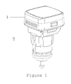
- FIG 1 showing a perspective view of an insertable indicator with a spare receptacle according to the invention.
- An insertable indicator with a spare receptacle includes a power getting plug inserted into a car power getting receptacle and an indicating component 1 disposed on the power getting plug 2.
- the indicating component 1 is powered by the power getting plug 2 so as to operate normally.
- the indicating component 1 includes an enclosure 11 composed of a number of parts and electronics disposed inside the enclosure 11.
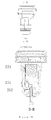
- the enclosure 11 includes an upper casing 111, a base 112, an upper cover 113 and a transparent element 114.
- the enclosure 11 may take on square shape (as shown in figure 2 ) or circle shape.
- the upper casing 111 and base 112 are erectly assembled together to define a receiving space for receiving said electronics.
- the electronics has a display screen 12 for displaying video information such as data and image.
- the display screen 12 includes a control circuit 121, a LCD panel 123 electrically connected to the control circuit 121, and a back light panel 122.
- the control circuit 121 is positioned on the base 112 and is secured thereon by a plurality of limiting grooves of the base 112.
- the back light panel 122 is stacked on the control circuit 121, and the LCD panel 123 is in turn stacked on the back light panel 122.
- the control circuit 121 processes signals input therein and then the LCD panel 123 displays them. Next, the back light panel 122 is switched on to illuminate the LCD panel 123.
- a transparent element 114 is provided on the screen 12.
- the transparent element 114 is fastened by an upper cover 113 sleeved on the upper casing 111.
- An aperture is defined in the upper casing 111 for accommodating said transparent element 114 thus providing a transparent window.
- a tire pressure status instrument is produced by addition of other functional components to the indicating component 1.
- the tire pressure status instrument further includes a tire pressure monitor circuit and a tire pressure signal receiving antenna.
- the tire pressure monitor circuit is integrated with the control circuit 121 of the screen 12, and they are both printed on a same circuit board.
- the tire pressure signal receiving antenna takes form of antenna sheet 13. As shown in figure 2 , the antenna sheet 13 is tightly pressed against a frame of the upper casing 111 of the indicator and is of a square frame shape.
- a plurality of supporting legs 131 is extended downwardly from the antenna sheet 13 for securing other components.
- the periphery of the back light panel 122 is provided with several holding brackets 1221 for locating said supporting legs 131.
- the antenna sheet 13 is located in place by said holding brackets 1221 of the back light panel 122. Then, the antenna sheet 13 is electrically connected with the control circuit 121 held below the back light panel 122. In case that the enclosure 11 is of circle, the antenna sheet 13 will correspondingly be of circle.
- the tire pressure signal receiving antenna receives signals including tire pressure date transmitted from the car tire pressure gauge and then send them to the tire pressure monitor circuit.
- the tire pressure monitor circuit analyzes said tire pressure signals and outputs tire pressure information to the display screen under control of the control circuit such that the information will be displayed by said display screen.
- the power getting plug 2 includes:
- the indicating component 1 and power getting plug 2 are connected to each other by a pivoting construction.
- a pair of first pivoting portions 221 is formed at one side of an exposed end surface of the power getting plug of the lower cover 22.
- the pair of the pivoting portions takes form of a pair of ear portions each has a horizontal through hole defined therein as shown in figure 5.
- a groove 2211 is defined between the two ear portions.
- a pair of second pivoting portions 1121 is formed on the base 112 at the same side adjacent the bottom surface of the base (or they may be directly formed on the bottom surface) .
- the pair of second pivoting portions 1121 engages the first pivoting portions 221.
- an ear portion with a horizontal through hole is formed as shown in figure 5 .
- This ear portion may be inserted into the groove 2211 and be located coaxially with the through holes of the first pivoting portions 221.
- a rotation shaft 222 may be installed into theses through holes.
- the indicating component may rotate relative to the power getting plug via said shaft.
- a friction cushion 223 is placed on a contact arc surface between the second pivoting portion 1121 and groove 2211 for increasing friction force between the first and second pivoting portions 221, 1121.
- the indicating component 1 and USB conversion circuit 23 are connected with each other in parallel.
- the USB conversion circuit 23 is connected with the positive and negative electrodes of the car power getting receptacle through the positive and negative electrode connecting elements 24 and 25 respectively.
- the indicating component 1 is electrically connected to the positive and negative electrodes of the car power getting receptacle through well known lead lines (not shown).
- a through hole is defined in the lower cover 22 at a location between its rectangular through hole 224 and second pivoting portion 1121 through which a lead line passes and connects to the indicating component 1 so as to obtain power.
- a plurality of auxiliary components 14 are also provided to the indicator. It includes a button tab 141 for clasping the base 112 and lover cover 22, a corresponding spring 142, a button 143 for controlling displayed contents on the display screen 12, and an indicating lamp 145 for indicating power status.
- the insertable indicator with a spare receptacle according to the invention when used as a tire pressure status instrument, the power getting plug 2 is inserted into the power getting receptacle of the car.
- the display screen 12 When powered, the display screen 12 starts. According to desire, the driver may select to rotate the indicating component 1 so as to easily watch the displayed contents. At this time, the USB socket 231 which had been masked by the indicating component 1 is now exposed for use.
- the insertable indicator with a spare receptacle and tire pressure status instrument of the invention have small size, various functions, optimized design, are convenient for use and have expansive application.
Landscapes
- Engineering & Computer Science (AREA)
- Mechanical Engineering (AREA)
- Measuring Fluid Pressure (AREA)
- Details Of Connecting Devices For Male And Female Coupling (AREA)
- Fittings On The Vehicle Exterior For Carrying Loads, And Devices For Holding Or Mounting Articles (AREA)
- Instrument Panels (AREA)
Applications Claiming Priority (2)
| Application Number | Priority Date | Filing Date | Title |
|---|---|---|---|
| CN201210559341.3A CN103009941B (zh) | 2012-12-20 | 2012-12-20 | 带备用接口的插接式显示仪与胎压状态仪 |
| PCT/CN2013/071017 WO2014094382A1 (fr) | 2012-12-20 | 2013-01-28 | Dispositif d'affichage de type enfichable avec port en attente et manomètre pour pneus |
Publications (2)
| Publication Number | Publication Date |
|---|---|
| EP2937245A1 true EP2937245A1 (fr) | 2015-10-28 |
| EP2937245A4 EP2937245A4 (fr) | 2016-08-17 |
Family
ID=47959261
Family Applications (1)
| Application Number | Title | Priority Date | Filing Date |
|---|---|---|---|
| EP13865317.5A Withdrawn EP2937245A4 (fr) | 2012-12-20 | 2013-01-28 | Dispositif d'affichage de type enfichable avec port en attente et manomètre pour pneus |
Country Status (5)
| Country | Link |
|---|---|
| US (1) | US9266400B2 (fr) |
| EP (1) | EP2937245A4 (fr) |
| CN (1) | CN103009941B (fr) |
| RU (1) | RU153712U1 (fr) |
| WO (1) | WO2014094382A1 (fr) |
Families Citing this family (7)
| Publication number | Priority date | Publication date | Assignee | Title |
|---|---|---|---|---|
| CN105751831A (zh) * | 2016-03-01 | 2016-07-13 | 张泽婵 | 嵌入式胎压监测系统 |
| USD824788S1 (en) * | 2016-11-03 | 2018-08-07 | Lumileds Holding B.V. | Vehicle tire pressure monitoring system |
| CN107187280A (zh) * | 2017-05-27 | 2017-09-22 | 上海嘉铎电子科技有限公司 | 小汽车胎压监测系统 |
| DE102017118893A1 (de) * | 2017-08-18 | 2019-02-21 | Man Truck & Bus Ag | Halterung, insbesondere für eine Anzeigevorrichtung eines Kraftfahrzeug |
| CN109363352A (zh) * | 2018-12-21 | 2019-02-22 | 四川变体科技有限公司 | 一种人工智能讲台 |
| TWI778360B (zh) * | 2020-05-13 | 2022-09-21 | 周文三 | 汽車輪胎修補裝置之點菸器插頭 |
| CN117746750B (zh) * | 2023-11-28 | 2026-04-07 | 苏州元脑智能科技有限公司 | Lcd模组及电子设备 |
Family Cites Families (17)
| Publication number | Priority date | Publication date | Assignee | Title |
|---|---|---|---|---|
| SE9802054L (sv) * | 1998-06-10 | 1999-12-11 | Marcus Andersson | Anordning vid en mobiltelefonhållare |
| US6868718B1 (en) * | 2003-11-14 | 2005-03-22 | Wireless tire pressure alarming system as directly powered from car cigarette-lighter receptacle | |
| WO2005048397A2 (fr) * | 2003-11-17 | 2005-05-26 | Sst Wireless Inc. | Antenne de corps de machine |
| DE202004003279U1 (de) * | 2004-03-03 | 2004-06-03 | Brahimaj, Hamdi | Handyhalter/Getränkehalter |
| US20060125613A1 (en) * | 2004-12-03 | 2006-06-15 | Yueh-Ying Ko | Tire pressure detector and alarm system |
| US7024928B1 (en) * | 2005-01-14 | 2006-04-11 | Jui-Yu Chen | Multifunctional tire pressure gauge |
| US20070093279A1 (en) * | 2005-10-12 | 2007-04-26 | Craig Janik | Wireless headset system for the automobile |
| US7789523B2 (en) * | 2007-06-27 | 2010-09-07 | Arnold Iii Vaughn R | Receptacle positioned rechargeable flashlight |
| CN201113161Y (zh) * | 2007-09-14 | 2008-09-10 | 萧德富 | 带充电器的点烟筒母座 |
| CN101474973B (zh) * | 2009-01-16 | 2011-08-10 | 广东铁将军防盗设备有限公司 | 车载设备连接结构 |
| CN201576717U (zh) * | 2009-09-28 | 2010-09-08 | 浙江联龙电子电器有限公司 | 一种手机充电车载电源 |
| CN101767519B (zh) * | 2010-02-10 | 2013-05-01 | 广东铁将军防盗设备有限公司 | 车胎压力监测系统及其胎压车载装置 |
| US20120169272A1 (en) * | 2011-01-03 | 2012-07-05 | David Khalepari | Portable usb mini-charger device |
| CN102358116B (zh) * | 2011-09-13 | 2013-07-31 | 广东铁将军防盗设备有限公司 | 胎压监控系统及车载取电接口监视组件 |
| CN202474298U (zh) * | 2011-10-24 | 2012-10-03 | 唐扬模具股份有限公司 | 车用取电插座 |
| CN202695917U (zh) * | 2012-06-20 | 2013-01-23 | 酷赢生活文化传播(深圳)有限公司 | 车载充电转接装置 |
| CN203046768U (zh) * | 2012-12-20 | 2013-07-10 | 广东铁将军防盗设备有限公司 | 带备用接口的插接式显示仪与胎压状态仪 |
-
2012
- 2012-12-20 CN CN201210559341.3A patent/CN103009941B/zh not_active Expired - Fee Related
-
2013
- 2013-01-28 RU RU2014129639/11U patent/RU153712U1/ru not_active IP Right Cessation
- 2013-01-28 US US14/376,844 patent/US9266400B2/en not_active Expired - Fee Related
- 2013-01-28 EP EP13865317.5A patent/EP2937245A4/fr not_active Withdrawn
- 2013-01-28 WO PCT/CN2013/071017 patent/WO2014094382A1/fr not_active Ceased
Also Published As
| Publication number | Publication date |
|---|---|
| US9266400B2 (en) | 2016-02-23 |
| EP2937245A4 (fr) | 2016-08-17 |
| CN103009941A (zh) | 2013-04-03 |
| WO2014094382A1 (fr) | 2014-06-26 |
| RU153712U1 (ru) | 2015-07-27 |
| CN103009941B (zh) | 2015-12-16 |
| US20150035667A1 (en) | 2015-02-05 |
Similar Documents
| Publication | Publication Date | Title |
|---|---|---|
| US9266400B2 (en) | Insertable indicator with a spare receptacle and tire pressure status instrument | |
| JP2011037310A (ja) | 携帯用カーナビゲーション装置及び車両への取付具 | |
| KR20150135889A (ko) | 커버장치 및 이를 포함한 전자장치 | |
| US20110032219A1 (en) | Lever switch with display device | |
| JP6390323B2 (ja) | 車両用情報提供装置 | |
| JP2024038388A (ja) | 装置 | |
| JP2018060090A (ja) | 画像形成装置 | |
| US11747227B2 (en) | Electronic device including force key structure | |
| JP2014115192A (ja) | 車両用計器装置 | |
| JP2009166756A (ja) | 車載機器用支持具 | |
| JP6078761B2 (ja) | 電子機器 | |
| JP7673922B2 (ja) | 装置等 | |
| CN203046768U (zh) | 带备用接口的插接式显示仪与胎压状态仪 | |
| JP2024095705A (ja) | クレードル | |
| JP6533923B2 (ja) | 装置及びプログラム | |
| JP2016205979A (ja) | 計器装置 | |
| JP2014060048A (ja) | ステアリングスイッチ、ステアリングホイール | |
| JP4970606B1 (ja) | テレビジョン装置及び電子機器 | |
| JP5077051B2 (ja) | アンテナ取付構造および車載用機器 | |
| KR20220046204A (ko) | 차폐 커넥터 구조를 포함하는 전자 장치 | |
| JP2015152330A (ja) | 表示装置 | |
| CN218806284U (zh) | 一种摩托车仪表和摩托车 | |
| JP2015186974A (ja) | 車両用情報提供装置 | |
| JP2012153281A (ja) | 表示装置 | |
| CN108248386A (zh) | 一种带加速度指示的电动车仪表装置 |
Legal Events
| Date | Code | Title | Description |
|---|---|---|---|
| PUAI | Public reference made under article 153(3) epc to a published international application that has entered the european phase |
Free format text: ORIGINAL CODE: 0009012 |
|
| 17P | Request for examination filed |
Effective date: 20141104 |
|
| AK | Designated contracting states |
Kind code of ref document: A1 Designated state(s): AL AT BE BG CH CY CZ DE DK EE ES FI FR GB GR HR HU IE IS IT LI LT LU LV MC MK MT NL NO PL PT RO RS SE SI SK SM TR |
|
| AX | Request for extension of the european patent |
Extension state: BA ME |
|
| DAX | Request for extension of the european patent (deleted) | ||
| A4 | Supplementary search report drawn up and despatched |
Effective date: 20160715 |
|
| RIC1 | Information provided on ipc code assigned before grant |
Ipc: B60N 3/14 20060101ALI20160712BHEP Ipc: B60R 11/02 20060101AFI20160712BHEP Ipc: B60C 23/04 20060101ALI20160712BHEP Ipc: B60C 23/00 20060101ALI20160712BHEP Ipc: H02J 7/00 20060101ALI20160712BHEP Ipc: H01R 13/66 20060101ALI20160712BHEP |
|
| GRAP | Despatch of communication of intention to grant a patent |
Free format text: ORIGINAL CODE: EPIDOSNIGR1 |
|
| RIC1 | Information provided on ipc code assigned before grant |
Ipc: H02J 7/00 20060101ALI20160830BHEP Ipc: B60C 23/00 20060101ALI20160830BHEP Ipc: H01R 13/66 20060101ALI20160830BHEP Ipc: B60N 3/14 20060101ALI20160830BHEP Ipc: H01R 24/58 20110101ALI20160830BHEP Ipc: B60R 11/02 20060101AFI20160830BHEP Ipc: H01R 13/24 20060101ALI20160830BHEP Ipc: H01R 103/00 20060101ALI20160830BHEP Ipc: B60C 23/04 20060101ALI20160830BHEP |
|
| RIN1 | Information on inventor provided before grant (corrected) |
Inventor name: LI, ZHITAO |
|
| INTG | Intention to grant announced |
Effective date: 20161004 |
|
| STAA | Information on the status of an ep patent application or granted ep patent |
Free format text: STATUS: GRANT OF PATENT IS INTENDED |
|
| STAA | Information on the status of an ep patent application or granted ep patent |
Free format text: STATUS: THE APPLICATION IS DEEMED TO BE WITHDRAWN |
|
| 18D | Application deemed to be withdrawn |
Effective date: 20170215 |