EP2937255A2 - Dispositif d'estimation d'angle de roulis et appareil de transport - Google Patents
Dispositif d'estimation d'angle de roulis et appareil de transport Download PDFInfo
- Publication number
- EP2937255A2 EP2937255A2 EP15163918.4A EP15163918A EP2937255A2 EP 2937255 A2 EP2937255 A2 EP 2937255A2 EP 15163918 A EP15163918 A EP 15163918A EP 2937255 A2 EP2937255 A2 EP 2937255A2
- Authority
- EP
- European Patent Office
- Prior art keywords
- angular velocity
- roll angle
- estimation
- pitch
- estimated value
- Prior art date
- Legal status (The legal status is an assumption and is not a legal conclusion. Google has not performed a legal analysis and makes no representation as to the accuracy of the status listed.)
- Granted
Links
Images





Classifications
-
- G—PHYSICS
- G01—MEASURING; TESTING
- G01C—MEASURING DISTANCES, LEVELS OR BEARINGS; SURVEYING; NAVIGATION; GYROSCOPIC INSTRUMENTS; PHOTOGRAMMETRY OR VIDEOGRAMMETRY
- G01C19/00—Gyroscopes; Turn-sensitive devices using vibrating masses; Turn-sensitive devices without moving masses; Measuring angular rate using gyroscopic effects
-
- B—PERFORMING OPERATIONS; TRANSPORTING
- B60—VEHICLES IN GENERAL
- B60W—CONJOINT CONTROL OF VEHICLE SUB-UNITS OF DIFFERENT TYPE OR DIFFERENT FUNCTION; CONTROL SYSTEMS SPECIALLY ADAPTED FOR HYBRID VEHICLES; ROAD VEHICLE DRIVE CONTROL SYSTEMS FOR PURPOSES NOT RELATED TO THE CONTROL OF A PARTICULAR SUB-UNIT
- B60W40/00—Estimation or calculation of non-directly measurable driving parameters for road vehicle drive control systems not related to the control of a particular sub unit, e.g. by using mathematical models
- B60W40/10—Estimation or calculation of non-directly measurable driving parameters for road vehicle drive control systems not related to the control of a particular sub unit, e.g. by using mathematical models related to vehicle motion
- B60W40/11—Pitch movement
-
- B—PERFORMING OPERATIONS; TRANSPORTING
- B60—VEHICLES IN GENERAL
- B60W—CONJOINT CONTROL OF VEHICLE SUB-UNITS OF DIFFERENT TYPE OR DIFFERENT FUNCTION; CONTROL SYSTEMS SPECIALLY ADAPTED FOR HYBRID VEHICLES; ROAD VEHICLE DRIVE CONTROL SYSTEMS FOR PURPOSES NOT RELATED TO THE CONTROL OF A PARTICULAR SUB-UNIT
- B60W40/00—Estimation or calculation of non-directly measurable driving parameters for road vehicle drive control systems not related to the control of a particular sub unit, e.g. by using mathematical models
- B60W40/10—Estimation or calculation of non-directly measurable driving parameters for road vehicle drive control systems not related to the control of a particular sub unit, e.g. by using mathematical models related to vehicle motion
- B60W40/112—Roll movement
-
- G—PHYSICS
- G01—MEASURING; TESTING
- G01P—MEASURING LINEAR OR ANGULAR SPEED, ACCELERATION, DECELERATION, OR SHOCK; INDICATING PRESENCE, ABSENCE, OR DIRECTION, OF MOVEMENT
- G01P21/00—Testing or calibrating of apparatus or devices covered by the preceding groups
-
- G—PHYSICS
- G01—MEASURING; TESTING
- G01P—MEASURING LINEAR OR ANGULAR SPEED, ACCELERATION, DECELERATION, OR SHOCK; INDICATING PRESENCE, ABSENCE, OR DIRECTION, OF MOVEMENT
- G01P3/00—Measuring linear or angular speed; Measuring differences of linear or angular speeds
- G01P3/42—Devices characterised by the use of electric or magnetic means
- G01P3/44—Devices characterised by the use of electric or magnetic means for measuring angular speed
-
- B—PERFORMING OPERATIONS; TRANSPORTING
- B60—VEHICLES IN GENERAL
- B60W—CONJOINT CONTROL OF VEHICLE SUB-UNITS OF DIFFERENT TYPE OR DIFFERENT FUNCTION; CONTROL SYSTEMS SPECIALLY ADAPTED FOR HYBRID VEHICLES; ROAD VEHICLE DRIVE CONTROL SYSTEMS FOR PURPOSES NOT RELATED TO THE CONTROL OF A PARTICULAR SUB-UNIT
- B60W50/00—Details of control systems for road vehicle drive control not related to the control of a particular sub-unit, e.g. process diagnostic or vehicle driver interfaces
- B60W2050/0001—Details of the control system
- B60W2050/0002—Automatic control, details of type of controller or control system architecture
- B60W2050/0013—Optimal controllers
-
- B—PERFORMING OPERATIONS; TRANSPORTING
- B60—VEHICLES IN GENERAL
- B60W—CONJOINT CONTROL OF VEHICLE SUB-UNITS OF DIFFERENT TYPE OR DIFFERENT FUNCTION; CONTROL SYSTEMS SPECIALLY ADAPTED FOR HYBRID VEHICLES; ROAD VEHICLE DRIVE CONTROL SYSTEMS FOR PURPOSES NOT RELATED TO THE CONTROL OF A PARTICULAR SUB-UNIT
- B60W50/00—Details of control systems for road vehicle drive control not related to the control of a particular sub-unit, e.g. process diagnostic or vehicle driver interfaces
- B60W2050/0001—Details of the control system
- B60W2050/0019—Control system elements or transfer functions
- B60W2050/002—Integrating means
-
- B—PERFORMING OPERATIONS; TRANSPORTING
- B60—VEHICLES IN GENERAL
- B60W—CONJOINT CONTROL OF VEHICLE SUB-UNITS OF DIFFERENT TYPE OR DIFFERENT FUNCTION; CONTROL SYSTEMS SPECIALLY ADAPTED FOR HYBRID VEHICLES; ROAD VEHICLE DRIVE CONTROL SYSTEMS FOR PURPOSES NOT RELATED TO THE CONTROL OF A PARTICULAR SUB-UNIT
- B60W50/00—Details of control systems for road vehicle drive control not related to the control of a particular sub-unit, e.g. process diagnostic or vehicle driver interfaces
- B60W2050/0001—Details of the control system
- B60W2050/0019—Control system elements or transfer functions
- B60W2050/0027—Minimum/maximum value selectors
-
- B—PERFORMING OPERATIONS; TRANSPORTING
- B60—VEHICLES IN GENERAL
- B60W—CONJOINT CONTROL OF VEHICLE SUB-UNITS OF DIFFERENT TYPE OR DIFFERENT FUNCTION; CONTROL SYSTEMS SPECIALLY ADAPTED FOR HYBRID VEHICLES; ROAD VEHICLE DRIVE CONTROL SYSTEMS FOR PURPOSES NOT RELATED TO THE CONTROL OF A PARTICULAR SUB-UNIT
- B60W50/00—Details of control systems for road vehicle drive control not related to the control of a particular sub-unit, e.g. process diagnostic or vehicle driver interfaces
- B60W2050/0001—Details of the control system
- B60W2050/0043—Signal treatments, identification of variables or parameters, parameter estimation or state estimation
- B60W2050/005—Sampling
-
- B—PERFORMING OPERATIONS; TRANSPORTING
- B60—VEHICLES IN GENERAL
- B60W—CONJOINT CONTROL OF VEHICLE SUB-UNITS OF DIFFERENT TYPE OR DIFFERENT FUNCTION; CONTROL SYSTEMS SPECIALLY ADAPTED FOR HYBRID VEHICLES; ROAD VEHICLE DRIVE CONTROL SYSTEMS FOR PURPOSES NOT RELATED TO THE CONTROL OF A PARTICULAR SUB-UNIT
- B60W50/00—Details of control systems for road vehicle drive control not related to the control of a particular sub-unit, e.g. process diagnostic or vehicle driver interfaces
- B60W2050/0001—Details of the control system
- B60W2050/0043—Signal treatments, identification of variables or parameters, parameter estimation or state estimation
- B60W2050/0052—Filtering, filters
- B60W2050/0054—Cut-off filters, retarders, delaying means, dead zones, threshold values or cut-off frequency
- B60W2050/0056—Low-pass filters
-
- B—PERFORMING OPERATIONS; TRANSPORTING
- B60—VEHICLES IN GENERAL
- B60W—CONJOINT CONTROL OF VEHICLE SUB-UNITS OF DIFFERENT TYPE OR DIFFERENT FUNCTION; CONTROL SYSTEMS SPECIALLY ADAPTED FOR HYBRID VEHICLES; ROAD VEHICLE DRIVE CONTROL SYSTEMS FOR PURPOSES NOT RELATED TO THE CONTROL OF A PARTICULAR SUB-UNIT
- B60W50/00—Details of control systems for road vehicle drive control not related to the control of a particular sub-unit, e.g. process diagnostic or vehicle driver interfaces
- B60W50/02—Ensuring safety in case of control system failures, e.g. by diagnosing, circumventing or fixing failures
- B60W50/0205—Diagnosing or detecting failures; Failure detection models
- B60W2050/0215—Sensor drifts or sensor failures
-
- B—PERFORMING OPERATIONS; TRANSPORTING
- B60—VEHICLES IN GENERAL
- B60W—CONJOINT CONTROL OF VEHICLE SUB-UNITS OF DIFFERENT TYPE OR DIFFERENT FUNCTION; CONTROL SYSTEMS SPECIALLY ADAPTED FOR HYBRID VEHICLES; ROAD VEHICLE DRIVE CONTROL SYSTEMS FOR PURPOSES NOT RELATED TO THE CONTROL OF A PARTICULAR SUB-UNIT
- B60W2300/00—Indexing codes relating to the type of vehicle
- B60W2300/36—Cycles; Motorcycles; Scooters
-
- B—PERFORMING OPERATIONS; TRANSPORTING
- B60—VEHICLES IN GENERAL
- B60W—CONJOINT CONTROL OF VEHICLE SUB-UNITS OF DIFFERENT TYPE OR DIFFERENT FUNCTION; CONTROL SYSTEMS SPECIALLY ADAPTED FOR HYBRID VEHICLES; ROAD VEHICLE DRIVE CONTROL SYSTEMS FOR PURPOSES NOT RELATED TO THE CONTROL OF A PARTICULAR SUB-UNIT
- B60W2420/00—Indexing codes relating to the type of sensors based on the principle of their operation
- B60W2420/90—Single sensor for two or more measurements
- B60W2420/905—Single sensor for two or more measurements the sensor being an xyz axis sensor
-
- B—PERFORMING OPERATIONS; TRANSPORTING
- B60—VEHICLES IN GENERAL
- B60W—CONJOINT CONTROL OF VEHICLE SUB-UNITS OF DIFFERENT TYPE OR DIFFERENT FUNCTION; CONTROL SYSTEMS SPECIALLY ADAPTED FOR HYBRID VEHICLES; ROAD VEHICLE DRIVE CONTROL SYSTEMS FOR PURPOSES NOT RELATED TO THE CONTROL OF A PARTICULAR SUB-UNIT
- B60W2520/00—Input parameters relating to overall vehicle dynamics
- B60W2520/10—Longitudinal speed
-
- B—PERFORMING OPERATIONS; TRANSPORTING
- B60—VEHICLES IN GENERAL
- B60W—CONJOINT CONTROL OF VEHICLE SUB-UNITS OF DIFFERENT TYPE OR DIFFERENT FUNCTION; CONTROL SYSTEMS SPECIALLY ADAPTED FOR HYBRID VEHICLES; ROAD VEHICLE DRIVE CONTROL SYSTEMS FOR PURPOSES NOT RELATED TO THE CONTROL OF A PARTICULAR SUB-UNIT
- B60W2520/00—Input parameters relating to overall vehicle dynamics
- B60W2520/10—Longitudinal speed
- B60W2520/105—Longitudinal acceleration
-
- B—PERFORMING OPERATIONS; TRANSPORTING
- B60—VEHICLES IN GENERAL
- B60W—CONJOINT CONTROL OF VEHICLE SUB-UNITS OF DIFFERENT TYPE OR DIFFERENT FUNCTION; CONTROL SYSTEMS SPECIALLY ADAPTED FOR HYBRID VEHICLES; ROAD VEHICLE DRIVE CONTROL SYSTEMS FOR PURPOSES NOT RELATED TO THE CONTROL OF A PARTICULAR SUB-UNIT
- B60W2520/00—Input parameters relating to overall vehicle dynamics
- B60W2520/12—Lateral speed
- B60W2520/125—Lateral acceleration
-
- B—PERFORMING OPERATIONS; TRANSPORTING
- B60—VEHICLES IN GENERAL
- B60W—CONJOINT CONTROL OF VEHICLE SUB-UNITS OF DIFFERENT TYPE OR DIFFERENT FUNCTION; CONTROL SYSTEMS SPECIALLY ADAPTED FOR HYBRID VEHICLES; ROAD VEHICLE DRIVE CONTROL SYSTEMS FOR PURPOSES NOT RELATED TO THE CONTROL OF A PARTICULAR SUB-UNIT
- B60W2520/00—Input parameters relating to overall vehicle dynamics
- B60W2520/16—Pitch
-
- B—PERFORMING OPERATIONS; TRANSPORTING
- B60—VEHICLES IN GENERAL
- B60W—CONJOINT CONTROL OF VEHICLE SUB-UNITS OF DIFFERENT TYPE OR DIFFERENT FUNCTION; CONTROL SYSTEMS SPECIALLY ADAPTED FOR HYBRID VEHICLES; ROAD VEHICLE DRIVE CONTROL SYSTEMS FOR PURPOSES NOT RELATED TO THE CONTROL OF A PARTICULAR SUB-UNIT
- B60W2520/00—Input parameters relating to overall vehicle dynamics
- B60W2520/18—Roll
-
- B—PERFORMING OPERATIONS; TRANSPORTING
- B60—VEHICLES IN GENERAL
- B60W—CONJOINT CONTROL OF VEHICLE SUB-UNITS OF DIFFERENT TYPE OR DIFFERENT FUNCTION; CONTROL SYSTEMS SPECIALLY ADAPTED FOR HYBRID VEHICLES; ROAD VEHICLE DRIVE CONTROL SYSTEMS FOR PURPOSES NOT RELATED TO THE CONTROL OF A PARTICULAR SUB-UNIT
- B60W2520/00—Input parameters relating to overall vehicle dynamics
- B60W2520/28—Wheel speed
-
- B—PERFORMING OPERATIONS; TRANSPORTING
- B60—VEHICLES IN GENERAL
- B60Y—INDEXING SCHEME RELATING TO ASPECTS CROSS-CUTTING VEHICLE TECHNOLOGY
- B60Y2200/00—Type of vehicle
- B60Y2200/10—Road Vehicles
- B60Y2200/12—Motorcycles, Trikes; Quads; Scooters
Definitions
- the present invention relates to a roll angle estimation device, e.g. for estimating a roll angle of a moving body, such as a straddle-type vehicle or saddle-ride type vehicle or a vehicle body of a straddle-type vehicle or saddle-ride type vehicle.
- the invention also relates to a transport apparatus, such as a straddle-type or saddle-ride vehicle.
- JP 2009-73466 (Toyota Central Res & Dev) describes a vehicle attitude estimation apparatus, in which a roll angle and a pitch angle are estimated based on detected values of longitudinal acceleration, lateral acceleration, vertical acceleration, yaw acceleration, and roll angular velocity of the vehicle motion, as well as an estimated value of longitudinal vehicle speed and an estimated value of pitch angular velocity.
- An object of at least one embodiment of the present invention is to provide a roll angle estimation device which is capable of estimating the roll angle of a moving body with an improved accuracy, and a transport apparatus including the same.
- An object of at least one embodiment of at least one aspect of the present invention is to obviate or at least mitigate one or more problems or disadvantages in the prior art.
- a roll angle estimation device for estimating a roll angle of a moving body, such as a vehicle, e.g. a straddle-type vehicle or saddle-ride type vehicle, or a vehicle body, e.g. a vehicle body of a straddle-type vehicle or saddle-ride type vehicle.
- the device may comprise first and second angular velocity detectors.
- the first and second angular velocity detectors may detect respective first and second angular velocities around first and second axes extending along at least two mutually different directions.
- the device may comprise first, second, and third acceleration detectors.
- the first, second and third acceleration detectors may detect respective first, second, and third accelerations along at least three mutually different directions.
- the device may comprise a velocity detector.
- the velocity detector may detect information relating to or concerning a moving velocity of the moving body in a direction of travel.
- the device may comprise arithmetic circuitry or an estimation section.
- the arithmetic circuitry or estimation section may be configured to estimate a roll angle of the moving body.
- the arithmetic circuitry or estimation section may be configured to estimate a pitch angle and a pitch angular velocity of the moving body.
- the arithmetic circuitry or estimation section may be configured to estimate at least one offset error of the first and second angular velocity detectors and the first, second, and third acceleration detectors.
- the arithmetic circuitry or estimation section may estimate the roll angle, pitch angle, and/or pitch angular velocity of the moving body and may estimate the at least one offset error, based on one or more of: detection values determined, measured or detected by the first and second angular velocity detectors; detection values determined, measured or detected by the first, second, and third acceleration detectors; a detection value determined, measured or detected by the velocity detector; estimated values of the roll angle, pitch angle, and pitch angular velocity resulting from a previous estimation operation; and/or an estimated value of the offset error resulting from the previous estimation operation.
- first and second angular velocities around first and second axes along at least two mutually different directions may be detected by the respective first and second angular velocity detectors.
- first, second, and third accelerations along at least three mutually different directions may be respectively detected by the respective first, second, and third acceleration detectors.
- information relating to or concerning a moving velocity of a moving body in a direction of travel may be detected by the velocity detector.
- the arithmetic circuitry or estimation section may estimate a roll angle of the moving body, and may estimate a pitch angle and a pitch angular velocity of the moving body and may estimate at least one offset error of the first and second angular velocity detectors and the first, second, and third acceleration detectors.
- the arithmetic circuitry or estimation section may estimate the roll angle, pitch angle, and/or pitch angular velocity of the moving body and may estimate the at least one offset error, based on one or more of detection values determined, measured or detected by the first and second angular velocity detectors, detection values determined, measured or detected by the first, second, and third acceleration detectors, a detection value determined, measured or detected by the velocity detector, estimated values of the roll angle, pitch angle, and pitch angular velocity resulting from a previous estimation operation, and/or an estimated value of the offset error resulting from the previous estimation operation.
- a roll angle and also an offset error may be estimated.
- An estimated value of the offset error may be used for a next or subsequent estimation operation. This may compensate for a decrease in the accuracy of estimation of the roll angle by utilizing the roll angle, pitch angle, and pitch angular velocity of the moving body, and at least one offset error of the first and second angular velocity detectors and the first, second, and third acceleration detectors. As a result, the roll angle may be estimated with high or improved accuracy.
- the first angular velocity detector may detect a roll angular velocity.
- the second angular velocity detector may detect a yaw angular velocity.
- the first, second, and third acceleration detectors may detect respective first, second, and third accelerations along three mutually different directions.
- first and second angular velocity detectors may detect roll angular velocity and yaw angular velocity.
- first, second, and third accelerations along mutually different first, second, and third directions may be detected by the respective first, second, and third acceleration detectors.
- the arithmetic circuitry or estimation section may estimate a pitch angle based on the estimated value of the pitch angular velocity from the previous estimation operation.
- the arithmetic circuitry or estimation section may estimate a pitch angular velocity based on the estimated value of the pitch angular velocity determined by or resulting from the previous estimation operation.
- the arithmetic circuitry or estimation section may estimate a pitch angle based on a value obtained by integrating the estimated value of the pitch angular velocity from the previous estimation operation over a time interval between the current or present estimation operation and the previous estimation operation.
- the arithmetic circuitry or estimation section may estimate a pitch angular velocity based on a value obtained by integrating the estimated value of the pitch angular velocity from the previous estimation operation with a constant containing a time constant.
- the arithmetic circuitry may comprise a Kalman filter.
- the Kalman filter may, estimate the roll angle, pitch angle, and/or pitch angular velocity of the moving body and may estimate the at least one offset error based on a relationship between one or more of: detection values measured, determined or detected by the first and second angular velocity detectors; detection values measured, determined or detected by the first, second, and third acceleration detectors; a detection value measured, determined or detected by the velocity detector; estimated values of the roll angle, pitch angle, and pitch angular velocity determined by or resulting from a previous estimation operation; and/or an estimated value of the offset error determined by or resulting from the previous estimation operation.
- the arithmetic circuitry may be easily implemented by using a Kalman filter algorithm.
- the Kalman filter may comprise a saturation limiting circuit.
- the saturation limiting circuit may, set the estimated value to the upper limit value.
- the saturation limiting circuit may set the estimated value to the lower limit value.
- the saturation limiting circuit may set the estimated value to the upper limit value when any estimated value exceeds an upper limit value of a predetermined range.
- the saturation limiting circuit may set the estimated value to the lower limit value at least with respect to the estimated values of the roll angle, the pitch angle, and/or an offset error of the pitch angular velocity.
- the accuracy of estimation of the roll angle may be further improved.
- the arithmetic circuitry or estimation section may include low-pass filters, which may receive outputs from the first and second angular velocity detectors, the first, second, and third accelerations detector, and/or the velocity detector.
- the arithmetic circuitry or estimation section may treat the outputs, which have been transmitted through the low-pass filters as the detection values of the respective first and second angular velocity detectors, the respective first, second, and third accelerations detector, and/or the respective velocity detector.
- the moving body may comprise a front wheel and a rear wheel.
- the velocity detector may include a rear-wheel rotational speed detector.
- the rear-wheel rotational speed detector may detect a rotational speed of the rear wheel as the information.
- the arithmetic circuitry or estimation section of the roll angle estimation device may be configured to further estimate a moving velocity of the moving body.
- the arithmetic circuitry or estimation section may estimate the roll angle of the moving body, the at least one offset error, and the moving velocity of the moving body, based on one or more of: the detection values determined, measured or detected by the first and second angular velocity detectors; the detection values determined, measured or detected by the first, second, and third acceleration detectors; a detection value determined, measured or detected by the rear-wheel speed detector; an estimated value of the roll angle determined by or resulting from a previous estimation operation; an estimated value of the offset error determined by or resulting from the previous estimation operation; and/or an estimated value of the moving velocity from the previous estimation operation.
- the moving body may comprise a front wheel and a rear wheel.
- the velocity detector may include a front-wheel rotational speed detector.
- the front-wheel rotational speed detector may detect a rotational speed of the front wheel.
- the velocity detector may include a rear-wheel rotational speed arithmetic circuitry or rear-wheel rotational speed estimation section.
- the rear-wheel rotational speed arithmetic circuitry or rear-wheel rotational speed estimation section may estimate a rotational speed of the rear wheel from a detection value determined, measured or detected by the front-wheel rotational speed detector as the information.
- the arithmetic circuitry or estimation section of the roll angle estimation device may be configured to further estimate a moving velocity of the moving body.
- the arithmetic circuitry or estimation section may estimate the roll angle of the moving body, the at least one offset error, and/or the moving velocity of moving body, based on one or more of: detection values measured, determined or detected by the first and second angular velocity detectors; detection values measured, determined or detected by the first, second, and third acceleration detectors; an estimated value estimated, obtained or determined by the rear-wheel rotational speed arithmetic circuitry; an estimated value of the roll angle determined by or resulting from a previous estimation operation; an estimated value of the offset error determined by or resulting from the previous estimation operation; and/or an estimated value of the moving velocity determined by or resulting from the previous estimation operation.
- a transport apparatus comprising: a (moving) body which is capable of moving; the roll angle estimation device for estimating a roll angle of the moving body according to the first aspect of the present invention; and a processing device.
- the processing device may process the roll angle estimated by the roll angle estimation device.
- the moving body may be, comprise or be comprised in a vehicle, such as a straddle-type vehicle or saddle-ride type vehicle.
- the moving body may be, comprise or be comprised in a vehicle body of a vehicle, such as a straddle-type vehicle or saddle-ride type vehicle.
- the processing device may be, comprise or be comprised in a navigation system and/or a headlight driver.
- the roll angle estimation device may estimate the roll angle of the moving body with a higher or improved accuracy.
- the processing section may be able to carry out processing which may involve the roll angle.
- An angular velocity detector may be more susceptible to offset errors than an acceleration detector. Therefore, an estimated value of the offset error of at least one of the first and second angular velocity detectors may be used for the next or subsequent estimation operation. As a result, the accuracy of the estimation of the roll angle may be sufficiently improved.
- the estimated value of the offset error of the first acceleration detector may be used in a next or subsequent estimation operation, to further improve the accuracy of the estimation of the roll angle in a range in which the roll angle may be small.
- the rotational speed of the rear wheel may be closer to the moving velocity of the moving body than the rotational speed of the front wheel. Therefore, the roll angle of the moving body, at least one offset error, and/or the moving velocity of the moving body may be estimated with a high or improved accuracy by using a detected value of the rotational speed of the rear wheel.
- the rear-wheel rotational speed arithmetic circuitry or estimation section may estimate the rotational speed of the rear wheel from a detection value determined, measured or detected by the front-wheel rotational speed detector.
- the roll angle of the moving body, at least one offset error, and/or the moving velocity of the moving body may be estimated with a high or improved accuracy, similarly to the case where a rear-wheel rotational speed detector may be provided.
- the roll angle of a moving body may be estimated with a high or improved accuracy.
- a method for estimating a roll angle of a moving body may comprise providing a roll angle estimation device.
- the roll angle estimation device may comprise any of the features of the roll angle estimation device according to the first aspect.
- the method may comprise detecting first and second angular velocities around first and second axes extending along at least two mutually different directions, e.g. using respective first and second angular velocity detectors of the roll angle estimation device.
- the method may comprise detecting first, second, and third accelerations along at least three mutually different directions, e.g. using respective first, second and third acceleration detectors of the roll angle estimation device.
- the method may comprise detecting information concerning or relating to a moving velocity of the moving body in a direction of travel, e.g. using a velocity information detector of the roll angle estimation device.
- the method may comprise estimating a roll angle, a pitch angle and/or a pitch angular velocity of the moving body and may comprise estimating at least one offset error of the first and second angular velocity detectors and the first, second, and third acceleration detectors, e.g. using an estimation section of the roll angle estimation device.
- the estimation section may estimate the roll angle, pitch angle, and/or pitch angular velocity of the moving body and may estimate the at least one offset error, based on one or more of: detection values detected by the first and second angular velocity detectors; detection values detected by the first, second, and third acceleration detectors; a detection value detected by the velocity information detector; estimated values of the roll angle, pitch angle, and pitch angular velocity from a previous estimation operation; and/or an estimated value of the offset error from the previous estimation operation.
- a computer program or computer program product may be comprised in or programmed into a processing device, e.g. the processing device of the transport apparatus according to the second aspect.
- the computer program or computer program product may be embodied on a carrier medium, such as a tangible and/or non-transient carrier medium.
- FIG. 1 is a schematic diagram showing a vehicle including a roll angle estimation device according to an embodiment of the present invention.
- the vehicle 100 in Figure 1 is a motorcycle, as an example of a straddle-type vehicle or saddle-ride type vehicle.
- the vehicle 100 includes a vehicle body 1.
- a front wheel 2 is attached at the front of the vehicle body 1, and a rear wheel 3 is attached at the rear of the vehicle body 1.
- a sensor group 5 is attached in the central portion of the vehicle body 1. Details of the sensor group 5 will be described below.
- a rear-wheel speed sensor 7 for detecting rotational speed of the rear wheel 3 is attached on the metal wheel of the rear wheel 3.
- ECU 20 is provided at the rear of the vehicle body 1.
- the ECU 20 is a hardware device, such as arithmetic circuitry or an estimation section, such as a computer, which includes, for example, one or more microprocessors, and one or more analog and/or digital filter device(s).
- the arithmetic circuitry carries out computer program codes or instructions to act as a machine or special purpose computer etc.
- the arithmetic circuitry functions as different components, such as a means or section(s) for implementing the functions/acts specified in the flowchart and/or block diagram block or blocks, by executing the computer program codes or instructions.
- Output signals from the sensor group 5 and the rear-wheel speed sensor 7 are supplied to the ECU 20.
- the ECU 20 controls the elements of the vehicle body 1 and estimates the roll angle of the vehicle body 1 and, for example, supplies the estimated roll angle to the navigation system 12 and the headlight driver 15.
- the sensor group 5, the rear-wheel speed sensor 7, and the ECU 20 constitute or form a roll angle estimation device 10.
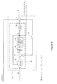
- FIG. 2 is a block diagram showing the construction of the roll angle estimation device 10 according to an embodiment of the present invention.
- the sensor group 5 includes: a roll angular velocity sensor 51, a yaw angular velocity sensor 52, an vertical acceleration sensor 53, a longitudinal acceleration sensor 54, and a lateral acceleration sensor 55.
- the roll angular velocity sensor 51 is provided on the vehicle body 1 to detect roll angular velocity of the vehicle body 1.
- Roll angular velocity is an angular velocity around or about the longitudinal axis of the vehicle 100.
- the yaw angular velocity sensor 52 is provided on the vehicle body 1 to detect yaw angular velocity of the vehicle body 1.
- Yaw angular velocity is an angular velocity around or about the vertical axis of the vehicle 100.
- the output signal of the roll angular velocity sensor 51 is supplied as a roll angular velocity to the Kalman filter 80 and the differentiator 71.
- the low-pass filter 61 removes noise from the output signal of the roll angular velocity sensor 51.
- the differentiator 71 supplies a differential of the roll angular velocity as a roll angular acceleration to the Kalman filter 80.
- the output signal of the yaw angular velocity sensor 52 is supplied as a yaw angular velocity to the Kalman filter 80 and the differentiator 72.
- the low-pass filter 62 removes noise from the output signal of the yaw angular velocity sensor 52.
- the differentiator 72 supplies a differential of the yaw angular velocity as a yaw angular acceleration to the Kalman filter 80.
- the output signal of the vertical acceleration sensor 53 is supplied as a vertical acceleration to the Kalman filter 80.
- the output signal of the longitudinal acceleration sensor 54 is supplied as a longitudinal acceleration to the Kalman filter 80.
- the output signal of the lateral acceleration sensor 55 is supplied as a lateral acceleration to the Kalman filter 80.
- the frequency characteristics of the respective low-pass filters 61 to 65 are set according to the output characteristics of the corresponding sensors 51 to 55. More specifically, the frequency characteristics of the noise signals contained in the output signals of the sensors 51 to 55 can be previously specified at the design phase.
- the low-pass filters 61 to 65 may be designed so as to cut off such noise signals while passing necessary detection signals from the sensors 51 to 55.
- the output signal of the rear-wheel speed sensor 7 is supplied as a rear-wheel speed to the Kalman filter 80.
- the rear-wheel speed is the rotational speed of the outermost periphery of the tire under the assumption that no skidding occurs between the road surface and the tire of the rear wheel 3.
- the rear-wheel speed is in use calculated from the output signal of the rear-wheel speed sensor 7 and the tire size. To simplify the explanation, it is assumed in Figure 2 that a signal indicating the rear-wheel speed is output from the rear-wheel speed sensor 7.
- the roll angular velocity, roll angular acceleration, yaw angular velocity, yaw angular acceleration, vertical acceleration, longitudinal acceleration, lateral acceleration, and rear-wheel speed are represented by symbols in the following table. Note that the single dot above the symbol representing any of these parameters indicates a first-order differentiation.
- the Kalman filter 80 estimates and outputs a roll angle, a vehicle speed, a roll angular velocity sensor offset, a yaw angular velocity sensor offset, an vertical acceleration sensor offset, a pitch angle, and a pitch angular velocity.
- the vertical plane that is parallel to the direction of travel of the vehicle 100 will be referred to as the longitudinal vertical plane, whereas the vertical plane that is perpendicular to the longitudinal vertical plane will be referred to as the lateral vertical plane.
- the roll angle is an angle of inclination of the vehicle body 1 with respect to the direction of gravity in the lateral vertical plane.
- Vehicle speed is the velocity of the vehicle body 1 along the direction of travel.
- the roll angular velocity sensor offset is an offset error of the roll angular velocity sensor 51; the yaw angular velocity sensor offset is an offset error of the yaw angular velocity sensor 52; and the vertical acceleration sensor offset is an offset error of the vertical acceleration sensor 53.
- the roll angular velocity sensor 51, the yaw angular velocity sensor 52, the vertical acceleration sensor 53, the longitudinal acceleration sensor 54, the lateral acceleration sensor 55, and the rear-wheel speed sensor 7 are used to derive seven relational expressions in eqs. (16), (17), and (19), which are shown below.
- the four parameters of the roll angle ⁇ , vehicle speed V x , pitch angle ⁇ , and pitch angular velocity ⁇ p are estimated.
- FIG 3 is a diagram showing the concept of the Kalman filter 80.
- a kinematic model 90 for the vehicle 100 is used.
- the Kalman filter 80 includes a system equation 8a, an adder 8b, an integrator 8c, a saturation limiting circuit 8d, an observation equation 8e, a subtracter 8f, and a Kalman gain 8g.
- the system equation 8a includes the mathematical function f(x,u); the observation equation 8e includes the mathematical function h(x); and the Kalman gain 8g includes septic Kalman gains K.
- the Kalman filter 80 is realized or provided by the ECU 20 shown in Figure 1 and also a computer program. More specifically, arithmetic operations of substituting respective input values to the system equation 8a and the observation equation 8e, as well as the addition calculation by the adder 8b, the integration calculation by the integrator 8c, the subsequently-described saturation limiting process by the saturation limiting circuit 8d, the subtraction calculation by the subtracter 8f, and the multiplication calculation by the Kalman gain 8g are realized or performed by the ECU 20 shown in Figure 1 by executing a computer program that is provided in advance.
- system equation 8a adder 8b, integrator 8c, saturation limiting circuit 8d, observation equation 8e, subtracter 8f, and Kalman gain 8g may be implemented as an independent piece(s) of hardware.
- a circuit state-estimation-amount saturation limiting circuit functioning as the saturation limiting circuit 8d may be mounted.
- a detected value of the roll angular velocity ⁇ r a detected value of the roll angular acceleration (e.g. a differential of the roll angular velocity ⁇ r ), a detected value of the yaw angular velocity ⁇ y , yaw angular acceleration (e.g. a differential of the yaw angular velocity ⁇ y ), and a detected value of the longitudinal acceleration G x are supplied as input parameters u of the system equation 8a.
- the outputs of the system equation 8a are a predicted differential of the roll angle ⁇ , a predicted differential of the vehicle speed V x , a predicted differential of the roll angular velocity sensor offset b r , a predicted differential of the yaw angular velocity sensor offset b y , a predicted differential of the vertical acceleration sensor offset b z , a predicted differential of the pitch angle ⁇ , and a predicted differential of the pitch angular velocity ⁇ p .
- Products of an output of the subtracter 8f and the septic Kalman gains K obtained from the previous estimation operation are added to the predicted differential of the roll angle ⁇ , predicted differential of the vehicle speed V x , predicted differential of the roll angular velocity sensor offset b r , predicted differential of the yaw angular velocity sensor offset b y , predicted differential of the vertical acceleration sensor offset b z , predicted differential of the pitch angle ⁇ , and predicted differential of the pitch angular velocity ⁇ p .
- an estimated differential of the roll angle ⁇ an estimated differential of the vehicle speed Vx, an estimated differential of the roll angular velocity sensor offset b r , an estimated differential of the yaw angular velocity sensor offset b y , as well as an estimated differential of the vertical acceleration sensor offset b z , an estimated differential of the pitch angle ⁇ , and an estimated differential of pitch angular velocity ⁇ p are obtained.
- the integrator 8c integrates the estimated differential of the roll angle ⁇ , estimated differential of the vehicle speed V x , estimated differential of the roll angular velocity sensor offset b r , estimated differential of the yaw angular velocity sensor offset b y , estimated differential of the vertical acceleration sensor offset b z , estimated differential of the pitch angle ⁇ , and estimated differential of the pitch angular velocity ⁇ p , in which the Kalman gain K is taken into account, thereby obtaining the following values in the current or present estimation operation: an estimated value of the roll angle ⁇ , an estimated value of the vehicle speed V x , an estimated value of the roll angular velocity sensor offset b r , an estimated value of the yaw angular velocity sensor offset b y , an estimated value of the vertical acceleration sensor offset b z , an estimated value of the pitch angle ⁇ , and an estimated value of the pitch angular velocity ⁇ p .
- the saturation limiting circuit 8d sets saturation characteristics for all of: the estimated value of the roll angular velocity sensor offset b r , the estimated value of the yaw angular velocity sensor offset b y , and the estimated value of the vertical acceleration sensor offset b z . For example, if the estimated value of the roll angular velocity sensor offset b r is greater than the upper limit value, the saturation limiting circuit 8d corrects the value to an upper limit value, and if it is smaller than the lower limit value, the saturation limiting circuit 8d corrects the value to a lower limit value. The same also applies to the estimated value of the yaw angular velocity sensor offset b y and the estimated value of the vertical acceleration sensor offset b z .
- the aforementioned three estimated values may not be all of the estimated values that the saturation limiting circuit 8d sets saturation characteristics for. Saturation characteristics may be set for the seven estimated values, which are to be integrated by the integrator 8c. This may prevent substantial deviation in the learned values with respect to all estimated values.
- an estimated value of the roll angle ⁇ As input parameters x for the observation equation 8e, an estimated value of the roll angle ⁇ , an estimated value of the vehicle speed V x , an estimated value of the roll angular velocity sensor offset b r , an estimated value of the yaw angular velocity sensor offset b y , an estimated value of the vertical acceleration sensor offset b z , an estimated value of the pitch angle ⁇ , and an estimated value of the pitch angular velocity ⁇ p are supplied. From the observation equation 8e, a calculated value of the vertical acceleration G z , a calculated value of the lateral acceleration G y , and a calculated value of the rear-wheel speed v r are obtained.
- the roll angle, differential of the roll angle, pitch angle, differential of the pitch angle, yaw angle, differential of the yaw angle, roll angular velocity, yaw angular velocity, and pitch angular velocity are represented by symbols in the following table.
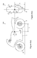
- Figure 4 is a diagram describing a position at which the sensor group 5 is attached.
- Figure 4(a) shows the left side of the vehicle 100
- Figure 4(b) shows the front of the vehicle 100
- Figure 5 is a vectorial representation of the attachment position of the sensor group 5.
- the attachment position of the sensor group 5 is denoted as PS.
- PS the attachment position of the sensor group 5
- Figure 5 the rear wheel 3 is inclined by the roll angle ⁇ relative to the road surface RD, which is inclined relative to the inertia coordinate system origin O by the pitch angle ⁇ .
- Figure 5 defines a position vector rv of the attachment position PS of the sensor group 5 relative to the origin O of the inertia coordinate system, a position vector rv 0 of a tangential point P relative to the origin O of the inertia coordinate system, and a vector pv extending from the tangential point P to the attachment position PS of the sensor group 5.
- a second-order differentiation vector of the position vector rv, a second-order differentiation vector of the position vector rv 0 , a second-order differentiation vector of the vector pv, and a gravitational acceleration vector are represented by symbols in the following table. Note that the double dots above the symbol represent any parameters indicate a second-order differentiation.
- Table 4 parameter definition .. second-order differentiation vector of position vector rv rv .. second-order differentiation vector of position vector rv 0 rv 0 ... second-order differentiation vector of attachment position vector pv pv gv gravitational acceleration vector
- the vector e 31 is a base vector of the vehicle body 1 along the forward direction;
- the vector e 32 is a base vector of the vehicle body 1 along the left direction;
- the vector e 33 is a base vector of the vehicle body 1 along the vertically upward direction.
- Equation 6 shown above a x , a y , and a z are mathematical functions.
- the mathematical functions a x , a y , and a z can be determined from the calculation of eqs. (4) and (5).
- Equation 6 shown above is obtained.
- V y the lateral skidding velocity of the vehicle 100 is denoted as V y .
- Equation 9 g represents the magnitude of gravitational acceleration.
- the acceleration vector Gv detected at the attachment position PS is expressed by the following equation, using the longitudinal acceleration G x detected by the longitudinal acceleration sensor 54, the lateral acceleration G y detected by the lateral acceleration sensor 55, and the vertical acceleration G z detected by the vertical acceleration sensor 53.
- Gv e ⁇ G x ⁇ G y ⁇ G z
- Equation 14 shown above as the system equation
- Equation 15 the observation equation
- the differential of the roll angular velocity sensor offset b r , the differential of the yaw angular velocity sensor offset b y , and the differential of the vertical acceleration sensor offset b z can be regarded as zero.
- Equation 14 by replacing the roll angular velocity ⁇ r , yaw angular velocity ⁇ y , and vertical acceleration G z in Equations 14 and 15 above with ⁇ r -b r , ⁇ y -b y , and G z -b z , respectively, the following equation is derived.
- Equations 16 and 17 above take into account the roll angular velocity sensor offset b r , the yaw angular velocity sensor offset b y , and the vertical acceleration sensor offset b z .
- parameter ⁇ represents an exponential decay factor.
- Parameter ⁇ p is a mathematical function of time t.
- Equation 16 and Equation 18 Equation 19 shown below is derived.
- Equation 19 corresponds to the mathematical function f(x,u) shown in Figure 3
- Equation 17 corresponds to the mathematical function h(x) shown in Figure 3 .
- An angular velocity sensor is more susceptible to offset errors than an acceleration sensor. Therefore, in the present embodiment, an offset error of the roll angular velocity sensor 51 (e.g. a roll angular velocity sensor offset b r ) and an offset error of the yaw angular velocity sensor 52 (e.g. a yaw angular velocity sensor offset b y ) are estimated.
- the roll angular velocity sensor offset b r and the estimated value of the yaw angular velocity sensor offset b y in a next or subsequent estimation operation, the accuracy of estimation of the roll angle ⁇ is sufficiently improved.
- the present embodiment estimates an offset error of the vertical acceleration sensor 53 (e.g. a vertical acceleration sensor offset b z ), for the following reasons.
- the vertical acceleration of the vehicle body 1 hardly changes.
- the estimated value of the vertical acceleration sensor offset b z is used in a next or subsequent estimation operation, to thereby further improve the accuracy of the estimation of the roll angle ⁇ in a range where the roll angle ⁇ is small.
- Figure 6(b) shows a result of a comparison between the estimated values of the pitch angle ⁇ and true pitch angle values.
- a solid line indicates estimated values, and a broken line indicates true values.
- a period R1 indicates a period of traveling flat terrain, and a period R2 indicates a period of traveling sloped terrain.
- Figures 7(a), 7(b) , and 7(c) are diagrams showing respective time transition of the estimated value of each parameter in the case where the roll angular velocity sensor 51 has an offset error and in the case where the roll angular velocity sensor 51 does not have any offset error.
- the roll angular velocity sensor 51, the yaw angular velocity sensor 52, the vertical acceleration sensor 53, the longitudinal acceleration sensor 54, the lateral acceleration sensor 55, and the rear-wheel speed sensor 7, each having no offset error, were attached to the vehicle 100, and the estimated values of the respective parameters were calculated based on detection values of the roll angular velocity sensor 51, the yaw angular velocity sensor 52, the vertical acceleration sensor 53, the longitudinal acceleration sensor 54, the lateral acceleration sensor 55, and the rear-wheel speed sensor 7 during actual travel. Moreover, an offset error of 3 degs/s was added to the detection value of the roll angular velocity sensor 51. Thus, the estimated values of the respective parameters were calculated.
- the difference between the estimated value of the roll angular velocity sensor offset b r in the case where an offset error is added to the detection value of the roll angular velocity sensor 51 and the estimated value of roll angular velocity sensor offset b r in the case where no offset error is added to the detection value of the roll angular velocity sensor 51 is equal to the value (3 degs/s) of the offset error.
- the estimated values of the yaw angular velocity sensor offset b y and the vertical acceleration sensor offset b z are both almost zero in the case where no offset error is added to the detection value of the roll angular velocity sensor 51 and in the case where an offset error is added to the detection value of the roll angular velocity sensor 51.
- the roll angle estimation device 10 of the present embodiment is able to estimate the roll angle ⁇ with high accuracy, even when the roll angular velocity sensor 51 has an offset error.
- the roll angle estimation device 10 of the present embodiment estimates the roll angular velocity sensor offset b r , yaw angular velocity sensor offset b y , vertical acceleration sensor offset b z , pitch angle ⁇ , and pitch angular velocity ⁇ p , as well as the roll angle ⁇ and the vehicle speed V x , and uses the estimated values of the roll angular velocity sensor offset b r , yaw angular velocity sensor offset b y , vertical acceleration sensor offset b z , pitch angle ⁇ , and pitch angular velocity ⁇ p in a next or subsequent estimation operation.
- an estimated value of the offset error of the vertical acceleration sensor 53 is used in the next or subsequent estimation operation. This further improves the accuracy of the estimation of the roll angle ⁇ in a range where the roll angle ⁇ is small.
- a detected value of the rear-wheel speed v r as detected by the rear-wheel speed sensor 7 is used in the estimation operation. This makes it possible to estimate the roll angle ⁇ of the vehicle body 1, the roll angular velocity sensor offset b r , the yaw angular velocity sensor offset b y , the vertical acceleration sensor offset b z , and the vehicle speed V x with high accuracy, even when the vehicle 100 turns in a small radius and with a low velocity.
- the roll angle estimation device 10 estimates the roll angle ⁇ of the vehicle body 1 with a high or improved accuracy.
- the navigation system 12 and the headlight driver 15 operate accurately, on the basis of the roll angle ⁇ estimated by the ECU 20.
- the rear-wheel speed sensor 7 for detecting the rotational speed of the rear wheel 3 is attached to the metal wheel of the rear wheel 3.
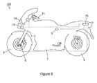
- a front-wheel speed sensor 6 for detecting the rotational speed of the front wheel 2 may be attached to the metal wheel of the front wheel 2, as shown in Figure 8.
- Figure 8 is a schematic diagram of a vehicle 100 including a roll angle estimation device according to another embodiment of the present invention.
- the above-described embodiment utilizes a rear-wheel speed v r which is detected by the rear-wheel speed sensor 7.
- a rear-wheel speed v r may be estimated from the front-wheel speed which is detected by the front-wheel speed sensor 6 shown in Figure 8 .
- the turning radius of the front wheel 2 becomes larger than the turning radius of the rear wheel 3. This makes the rotational speed of the front wheel 2 detected by the front-wheel speed sensor 6 higher than the rotational speed of the rear wheel 3. Accordingly, the ECU 20 estimates a rear-wheel speed v r from the rotational speed of the front wheel 2 which is detected by the front-wheel speed sensor 6.
- Equation 25 shown above has a solution only when the condition of the following equation is satisfied. Equation 26 V f 4 - 4 ⁇ La 2 ⁇ g 2 ⁇ tan 2 ⁇ ⁇ ⁇ 0
- Equation 27 The estimated value of the roll angle ⁇ from the previous estimation operation is used as the roll angle ⁇ in Equation 27 shown above.
- the rear-wheel speed V r can be calculated from the rotational speed of the front wheel 2 detected by the front-wheel speed sensor 6 (hereinafter referred to as the front-wheel speed V f ).
- the rear-wheel speed V r can be estimated from the front-wheel speed V f , which is detected by the front-wheel speed sensor 6. Therefore, even when only the front-wheel speed sensor 6 is provided, it is possible to estimate the roll angle ⁇ of the vehicle body 1, the vehicle speed V x , the roll angular velocity sensor offset b r , the yaw angular velocity sensor offset b y , and the vertical acceleration sensor offset b z with a high or improved accuracy, similarly to the case where the rear-wheel speed sensor 7 is provided.
- an angular velocity sensor which detects angular velocity around an axis in the lateral direction of the vehicle 100 may be used. In this case, the accuracy of estimation of the roll angle ⁇ may be further improved.
- three or more acceleration sensors may be used, which detect acceleration along three or more directions other than the vertical direction, the longitudinal direction, and the lateral direction of the vehicle 100.
- detection values detected, measured or determined by the three or more acceleration sensors may be converted into a vertical acceleration G z , a longitudinal acceleration G x , and a lateral acceleration G y by a geometric technique, so that Equations 16 and 17 above can be used.
- an offset error of the longitudinal acceleration sensor 54 may be estimated, or an offset error of the lateral acceleration sensor 55 may be estimated.
- the Kalman filter 80 estimates vehicle speed V x .
- the Kalman filter 80 does not need to estimate vehicle speed V x .
- any other adaptive filtering technique may be used.
- a least mean square (LMS) adaptive filter, H ⁇ filtering, or the like may be used.
- the first direction is an example of the vertical direction of the vehicle 100; the second direction is an example of the longitudinal direction of the vehicle 100; the third direction is an example of the lateral direction of the vehicle 100; vertical acceleration G z is an example of the first acceleration; longitudinal acceleration G x is an example of the second acceleration; lateral acceleration G y is an example of the third acceleration; the vertical acceleration sensor 53 is an example of the first acceleration detector; the longitudinal acceleration sensor 54 is an example of the second acceleration detector; and the lateral acceleration sensor 55 is an example of the third acceleration detector.
- the vehicle 100 or the vehicle body 1 is an example of the moving body;
- the front wheel 2 is an example of the front wheel;
- the rear wheel 3 is an example of the rear wheel;
- the rear-wheel speed sensor 7 is an example of the rear-wheel rotational speed detector;
- the front-wheel speed sensor 6 is an example of the front-wheel rotational speed detector;
- the ECU 20 is an example of the rear-wheel rotational speed estimation section, which is also referred to as rear-wheel rotational speed arithmetic circuitry.
- the present invention may take the form of an entirely hardware embodiment, an entirely software embodiment (including firmware, resident software, micro-code, etc.) or an embodiment combining software and hardware aspects that may all generally be referred to herein as a "circuit,” “module” or “system.”
- straddle-type vehicle or motor vehicle used herein, and as used in the art, is meant to include the following terms also used in the art:
Landscapes
- Engineering & Computer Science (AREA)
- Physics & Mathematics (AREA)
- Automation & Control Theory (AREA)
- Mathematical Physics (AREA)
- Transportation (AREA)
- Mechanical Engineering (AREA)
- General Physics & Mathematics (AREA)
- Radar, Positioning & Navigation (AREA)
- Remote Sensing (AREA)
- Control Of Driving Devices And Active Controlling Of Vehicle (AREA)
- Vehicle Body Suspensions (AREA)
- Length Measuring Devices With Unspecified Measuring Means (AREA)
Applications Claiming Priority (1)
| Application Number | Priority Date | Filing Date | Title |
|---|---|---|---|
| JP2014091519A JP6153493B2 (ja) | 2014-04-25 | 2014-04-25 | ロール角推定装置および輸送機器 |
Publications (3)
| Publication Number | Publication Date |
|---|---|
| EP2937255A2 true EP2937255A2 (fr) | 2015-10-28 |
| EP2937255A3 EP2937255A3 (fr) | 2016-10-05 |
| EP2937255B1 EP2937255B1 (fr) | 2018-12-19 |
Family
ID=52997268
Family Applications (1)
| Application Number | Title | Priority Date | Filing Date |
|---|---|---|---|
| EP15163918.4A Active EP2937255B1 (fr) | 2014-04-25 | 2015-04-16 | Dispositif d'estimation d'angle de roulis et appareil de transport |
Country Status (3)
| Country | Link |
|---|---|
| US (1) | US10502567B2 (fr) |
| EP (1) | EP2937255B1 (fr) |
| JP (1) | JP6153493B2 (fr) |
Cited By (3)
| Publication number | Priority date | Publication date | Assignee | Title |
|---|---|---|---|---|
| EP3441718A4 (fr) * | 2016-04-06 | 2019-05-01 | Yamaha Hatsudoki Kabushiki Kaisha | Dispositif d'estimation d'orientation et équipement de transport |
| CN110901657A (zh) * | 2018-09-14 | 2020-03-24 | 北汽福田汽车股份有限公司 | 车辆及油门踏板开度的解析方法、装置 |
| CN111325980A (zh) * | 2020-02-28 | 2020-06-23 | 浙江吉利汽车研究院有限公司 | 一种基于路况监测的驾驶方法、系统和装置 |
Families Citing this family (19)
| Publication number | Priority date | Publication date | Assignee | Title |
|---|---|---|---|---|
| FR3021605B1 (fr) * | 2014-06-03 | 2016-05-27 | Valeo Vision | Procede et systeme de correction de l’orientation des projecteurs d’un vehicule a moteur |
| DE112015006569B4 (de) * | 2015-05-27 | 2019-05-29 | Mitsubishi Electric Corporation | Optikachsensteuervorrichtung für Scheinwerfer |
| WO2017175840A1 (fr) | 2016-04-06 | 2017-10-12 | ヤマハ発動機株式会社 | Dispositif d'estimation d'orientation et équipement de transport |
| US9791279B1 (en) * | 2016-06-30 | 2017-10-17 | U-Blox Ag | System for and method of determining angular position of a vehicle |
| WO2018035282A1 (fr) * | 2016-08-17 | 2018-02-22 | Nano-Dimension Technologies, Ltd. | Procédés et bibliothèques destinés à être utilisés dans la bioimpression par jet d'encre de biostructures |
| JP6728393B2 (ja) * | 2016-11-29 | 2020-07-22 | ヤマハ発動機株式会社 | リーン車両の路面垂直方向軸周りの角速度取得装置 |
| KR101898629B1 (ko) * | 2017-09-12 | 2018-09-13 | 서강대학교산학협력단 | H-Infinity 필터를 이용한 기상 예측값 보정 방법 및 이를 이용한 기상 예측값 보정 장치 |
| JPWO2020158485A1 (ja) * | 2019-01-28 | 2021-12-02 | パナソニックIpマネジメント株式会社 | 複合センサおよび角速度補正方法 |
| JP7291231B2 (ja) * | 2019-09-27 | 2023-06-14 | 本田技研工業株式会社 | 車体姿勢検出装置及び鞍乗型車両 |
| US11332152B2 (en) * | 2020-05-29 | 2022-05-17 | GM Global Technology Operations LLC | Method and apparatus for determining a velocity of a vehicle |
| KR102170723B1 (ko) * | 2020-08-13 | 2020-10-27 | 주식회사 탑시스템 | 실내 바닥 미장층의 균열 방지기구 |
| EP4210975A4 (fr) * | 2020-09-07 | 2024-06-19 | Volvo Truck Corporation | Procédé de commande de suspensions pneumatiques, dispositif de commande de suspension pneumatique, système de suspension pneumatique, véhicule, programme informatique et support lisible par ordinateur |
| JP7567518B2 (ja) * | 2021-02-01 | 2024-10-16 | セイコーエプソン株式会社 | 減速機の角度伝達誤差補正方法およびロボットシステム |
| JP2023011375A (ja) * | 2021-07-12 | 2023-01-24 | 日立Astemo株式会社 | サスペンション制御装置およびサスペンション制御方法 |
| CN117730029A (zh) * | 2021-07-29 | 2024-03-19 | 罗伯特·博世有限公司 | 行动控制装置、倾斜车辆及行动控制方法 |
| US20240416909A1 (en) * | 2023-06-16 | 2024-12-19 | Magna Electronics Inc. | Vehicular driving assistance system with vehicle state estimation |
| CN121419916A (zh) | 2023-07-31 | 2026-01-27 | 安斯泰莫株式会社 | 侧倾角计算装置和侧倾角计算方法 |
| US20250067766A1 (en) * | 2023-08-24 | 2025-02-27 | Fca Us Llc | Method of longitudinal accelerometer rationalization with a wheel speed sensor |
| FR3165683A1 (fr) * | 2024-08-20 | 2026-02-27 | Vitesco Technologies | Procédé d’atténuation des perturbations de la mesure d’un angle d’inclinaison d’un véhicule |
Citations (1)
| Publication number | Priority date | Publication date | Assignee | Title |
|---|---|---|---|---|
| JP2009073466A (ja) | 2007-08-27 | 2009-04-09 | Toyota Central R&D Labs Inc | 車両姿勢角推定装置及びプログラム |
Family Cites Families (13)
| Publication number | Priority date | Publication date | Assignee | Title |
|---|---|---|---|---|
| US6002974A (en) * | 1998-02-06 | 1999-12-14 | Delco Electronics Corporation | Vehicle rollover sensing using extended kalman filter |
| US6292759B1 (en) * | 1998-11-19 | 2001-09-18 | Delphi Technologies, Inc. | Vehicle attitude angle estimation using sensed signal blending |
| US6330483B1 (en) * | 1999-05-07 | 2001-12-11 | The Boeing Company | Optimal control system |
| US20030058118A1 (en) * | 2001-05-15 | 2003-03-27 | Wilson Kitchener C. | Vehicle and vehicle tire monitoring system, apparatus and method |
| EP1970005B1 (fr) * | 2007-03-15 | 2012-10-03 | Xsens Holding B.V. | Système et procédé du suivi du mouvement en utilisant une unité d'étalonnage |
| JP5173854B2 (ja) * | 2008-04-21 | 2013-04-03 | 株式会社豊田中央研究所 | センサドリフト量推定装置 |
| US8188745B2 (en) * | 2008-12-05 | 2012-05-29 | Metrotech Corporation Inc. | Precise location and orientation of a concealed dipole transmitter |
| JP5128457B2 (ja) | 2008-12-18 | 2013-01-23 | 株式会社豊田中央研究所 | 車両姿勢角推定装置及びプログラム |
| JP5134527B2 (ja) * | 2008-12-25 | 2013-01-30 | 川崎重工業株式会社 | 自動二輪車のバンク角検知装置およびヘッドランプ装置 |
| JP5393432B2 (ja) * | 2009-12-21 | 2014-01-22 | ヤマハ発動機株式会社 | ロール角推定装置および輸送機器 |
| EP2610605B1 (fr) * | 2010-08-26 | 2023-04-12 | Nissan Motor Co., Ltd. | Dispositif permettant d'estimer une vibration de carcasse de véhicule et contrôleur correspondant permettant de supprimer une vibration de carcasse de véhicule |
| US8694251B2 (en) * | 2010-11-25 | 2014-04-08 | Texas Instruments Incorporated | Attitude estimation for pedestrian navigation using low cost mems accelerometer in mobile applications, and processing methods, apparatus and systems |
| US8575879B2 (en) * | 2011-08-19 | 2013-11-05 | GM Global Technology Operations LLC | Methods, systems and apparatus for controlling a multi-phase inverter |
-
2014
- 2014-04-25 JP JP2014091519A patent/JP6153493B2/ja active Active
-
2015
- 2015-04-16 EP EP15163918.4A patent/EP2937255B1/fr active Active
- 2015-04-22 US US14/693,092 patent/US10502567B2/en active Active
Patent Citations (1)
| Publication number | Priority date | Publication date | Assignee | Title |
|---|---|---|---|---|
| JP2009073466A (ja) | 2007-08-27 | 2009-04-09 | Toyota Central R&D Labs Inc | 車両姿勢角推定装置及びプログラム |
Cited By (4)
| Publication number | Priority date | Publication date | Assignee | Title |
|---|---|---|---|---|
| EP3441718A4 (fr) * | 2016-04-06 | 2019-05-01 | Yamaha Hatsudoki Kabushiki Kaisha | Dispositif d'estimation d'orientation et équipement de transport |
| US10634694B2 (en) | 2016-04-06 | 2020-04-28 | Yamaha Hatsudoki Kabushiki Kaisha | Attitude estimation apparatus and transportation machine |
| CN110901657A (zh) * | 2018-09-14 | 2020-03-24 | 北汽福田汽车股份有限公司 | 车辆及油门踏板开度的解析方法、装置 |
| CN111325980A (zh) * | 2020-02-28 | 2020-06-23 | 浙江吉利汽车研究院有限公司 | 一种基于路况监测的驾驶方法、系统和装置 |
Also Published As
| Publication number | Publication date |
|---|---|
| EP2937255A3 (fr) | 2016-10-05 |
| US10502567B2 (en) | 2019-12-10 |
| EP2937255B1 (fr) | 2018-12-19 |
| JP2015209106A (ja) | 2015-11-24 |
| US20150308827A1 (en) | 2015-10-29 |
| JP6153493B2 (ja) | 2017-06-28 |
Similar Documents
| Publication | Publication Date | Title |
|---|---|---|
| EP2937255B1 (fr) | Dispositif d'estimation d'angle de roulis et appareil de transport | |
| JP5393432B2 (ja) | ロール角推定装置および輸送機器 | |
| EP2942254B1 (fr) | Dispositif d'estimation d'angle de roulis d'un véhicule | |
| US10330469B2 (en) | Bank angle detection device for vehicle | |
| JP5029442B2 (ja) | 車両姿勢角推定装置及びプログラム | |
| CN107074241A (zh) | 估计车辆侧滑角度的方法、实施所述方法的计算机程序、装载有所述计算机程序的控制单元以及包括所述控制单元的车辆 | |
| EP3441718A1 (fr) | Dispositif d'estimation d'orientation et équipement de transport | |
| US11002539B2 (en) | Method for detecting a slope of a road | |
| US20050201593A1 (en) | Vehicle state sensing system and vehicle state sensing method | |
| EP3415393B1 (fr) | Dispositif d'estimation d'attitude et machine de transport | |
| US10442463B2 (en) | Method and device for ascertaining the steering angle of a one-track vehicle | |
| CN112985843B (zh) | 车轮定位失调的检测方法、检测装置及终端 | |
| JP5137792B2 (ja) | 車両横力外乱推定装置 | |
| JP2010089577A (ja) | 車両のスタビリティファクタ推定装置 | |
| JP7012001B2 (ja) | 車両の姿勢推定装置 | |
| JP5887988B2 (ja) | 傾斜角度検出装置 | |
| JP2013112079A (ja) | 車両姿勢制御装置 | |
| US20250162677A1 (en) | Method and Device for Determining the Load State of a Motorcycle | |
| CN119975623B (zh) | 车辆转弯半径检测方法、车辆控制方法、设备及存储介质 | |
| JP6171865B2 (ja) | 倒立二輪車 | |
| JP2009166587A (ja) | 車両用ヨーレート演算装置 | |
| JP2008051594A (ja) | 車輪角加速度検出装置、自動車及び車輪角加速度検出方法 |
Legal Events
| Date | Code | Title | Description |
|---|---|---|---|
| PUAI | Public reference made under article 153(3) epc to a published international application that has entered the european phase |
Free format text: ORIGINAL CODE: 0009012 |
|
| 17P | Request for examination filed |
Effective date: 20150416 |
|
| AK | Designated contracting states |
Kind code of ref document: A2 Designated state(s): AL AT BE BG CH CY CZ DE DK EE ES FI FR GB GR HR HU IE IS IT LI LT LU LV MC MK MT NL NO PL PT RO RS SE SI SK SM TR |
|
| AX | Request for extension of the european patent |
Extension state: BA ME |
|
| PUAL | Search report despatched |
Free format text: ORIGINAL CODE: 0009013 |
|
| AK | Designated contracting states |
Kind code of ref document: A3 Designated state(s): AL AT BE BG CH CY CZ DE DK EE ES FI FR GB GR HR HU IE IS IT LI LT LU LV MC MK MT NL NO PL PT RO RS SE SI SK SM TR |
|
| AX | Request for extension of the european patent |
Extension state: BA ME |
|
| RIC1 | Information provided on ipc code assigned before grant |
Ipc: B60W 40/112 20120101AFI20160826BHEP Ipc: B60W 50/00 20060101ALN20160826BHEP Ipc: B60W 40/11 20120101ALI20160826BHEP Ipc: B60W 50/02 20120101ALN20160826BHEP |
|
| STAA | Information on the status of an ep patent application or granted ep patent |
Free format text: STATUS: EXAMINATION IS IN PROGRESS |
|
| 17Q | First examination report despatched |
Effective date: 20170821 |
|
| GRAP | Despatch of communication of intention to grant a patent |
Free format text: ORIGINAL CODE: EPIDOSNIGR1 |
|
| STAA | Information on the status of an ep patent application or granted ep patent |
Free format text: STATUS: GRANT OF PATENT IS INTENDED |
|
| RIC1 | Information provided on ipc code assigned before grant |
Ipc: B60W 40/112 20120101AFI20180625BHEP Ipc: B60W 50/02 20120101ALN20180625BHEP Ipc: B60W 50/00 20060101ALN20180625BHEP Ipc: B60W 40/11 20120101ALI20180625BHEP |
|
| INTG | Intention to grant announced |
Effective date: 20180727 |
|
| GRAS | Grant fee paid |
Free format text: ORIGINAL CODE: EPIDOSNIGR3 |
|
| GRAA | (expected) grant |
Free format text: ORIGINAL CODE: 0009210 |
|
| STAA | Information on the status of an ep patent application or granted ep patent |
Free format text: STATUS: THE PATENT HAS BEEN GRANTED |
|
| AK | Designated contracting states |
Kind code of ref document: B1 Designated state(s): AL AT BE BG CH CY CZ DE DK EE ES FI FR GB GR HR HU IE IS IT LI LT LU LV MC MK MT NL NO PL PT RO RS SE SI SK SM TR |
|
| REG | Reference to a national code |
Ref country code: GB Ref legal event code: FG4D |
|
| REG | Reference to a national code |
Ref country code: CH Ref legal event code: EP |
|
| REG | Reference to a national code |
Ref country code: IE Ref legal event code: FG4D |
|
| REG | Reference to a national code |
Ref country code: DE Ref legal event code: R096 Ref document number: 602015021749 Country of ref document: DE |
|
| REG | Reference to a national code |
Ref country code: AT Ref legal event code: REF Ref document number: 1078350 Country of ref document: AT Kind code of ref document: T Effective date: 20190115 |
|
| REG | Reference to a national code |
Ref country code: NL Ref legal event code: MP Effective date: 20181219 |
|
| PG25 | Lapsed in a contracting state [announced via postgrant information from national office to epo] |
Ref country code: LV Free format text: LAPSE BECAUSE OF FAILURE TO SUBMIT A TRANSLATION OF THE DESCRIPTION OR TO PAY THE FEE WITHIN THE PRESCRIBED TIME-LIMIT Effective date: 20181219 Ref country code: HR Free format text: LAPSE BECAUSE OF FAILURE TO SUBMIT A TRANSLATION OF THE DESCRIPTION OR TO PAY THE FEE WITHIN THE PRESCRIBED TIME-LIMIT Effective date: 20181219 Ref country code: BG Free format text: LAPSE BECAUSE OF FAILURE TO SUBMIT A TRANSLATION OF THE DESCRIPTION OR TO PAY THE FEE WITHIN THE PRESCRIBED TIME-LIMIT Effective date: 20190319 Ref country code: FI Free format text: LAPSE BECAUSE OF FAILURE TO SUBMIT A TRANSLATION OF THE DESCRIPTION OR TO PAY THE FEE WITHIN THE PRESCRIBED TIME-LIMIT Effective date: 20181219 Ref country code: LT Free format text: LAPSE BECAUSE OF FAILURE TO SUBMIT A TRANSLATION OF THE DESCRIPTION OR TO PAY THE FEE WITHIN THE PRESCRIBED TIME-LIMIT Effective date: 20181219 Ref country code: NO Free format text: LAPSE BECAUSE OF FAILURE TO SUBMIT A TRANSLATION OF THE DESCRIPTION OR TO PAY THE FEE WITHIN THE PRESCRIBED TIME-LIMIT Effective date: 20190319 |
|
| REG | Reference to a national code |
Ref country code: LT Ref legal event code: MG4D |
|
| REG | Reference to a national code |
Ref country code: AT Ref legal event code: MK05 Ref document number: 1078350 Country of ref document: AT Kind code of ref document: T Effective date: 20181219 |
|
| PG25 | Lapsed in a contracting state [announced via postgrant information from national office to epo] |
Ref country code: RS Free format text: LAPSE BECAUSE OF FAILURE TO SUBMIT A TRANSLATION OF THE DESCRIPTION OR TO PAY THE FEE WITHIN THE PRESCRIBED TIME-LIMIT Effective date: 20181219 Ref country code: SE Free format text: LAPSE BECAUSE OF FAILURE TO SUBMIT A TRANSLATION OF THE DESCRIPTION OR TO PAY THE FEE WITHIN THE PRESCRIBED TIME-LIMIT Effective date: 20181219 Ref country code: AL Free format text: LAPSE BECAUSE OF FAILURE TO SUBMIT A TRANSLATION OF THE DESCRIPTION OR TO PAY THE FEE WITHIN THE PRESCRIBED TIME-LIMIT Effective date: 20181219 Ref country code: GR Free format text: LAPSE BECAUSE OF FAILURE TO SUBMIT A TRANSLATION OF THE DESCRIPTION OR TO PAY THE FEE WITHIN THE PRESCRIBED TIME-LIMIT Effective date: 20190320 |
|
| PG25 | Lapsed in a contracting state [announced via postgrant information from national office to epo] |
Ref country code: NL Free format text: LAPSE BECAUSE OF FAILURE TO SUBMIT A TRANSLATION OF THE DESCRIPTION OR TO PAY THE FEE WITHIN THE PRESCRIBED TIME-LIMIT Effective date: 20181219 |
|
| PG25 | Lapsed in a contracting state [announced via postgrant information from national office to epo] |
Ref country code: ES Free format text: LAPSE BECAUSE OF FAILURE TO SUBMIT A TRANSLATION OF THE DESCRIPTION OR TO PAY THE FEE WITHIN THE PRESCRIBED TIME-LIMIT Effective date: 20181219 Ref country code: CZ Free format text: LAPSE BECAUSE OF FAILURE TO SUBMIT A TRANSLATION OF THE DESCRIPTION OR TO PAY THE FEE WITHIN THE PRESCRIBED TIME-LIMIT Effective date: 20181219 Ref country code: PT Free format text: LAPSE BECAUSE OF FAILURE TO SUBMIT A TRANSLATION OF THE DESCRIPTION OR TO PAY THE FEE WITHIN THE PRESCRIBED TIME-LIMIT Effective date: 20190419 Ref country code: PL Free format text: LAPSE BECAUSE OF FAILURE TO SUBMIT A TRANSLATION OF THE DESCRIPTION OR TO PAY THE FEE WITHIN THE PRESCRIBED TIME-LIMIT Effective date: 20181219 |
|
| PG25 | Lapsed in a contracting state [announced via postgrant information from national office to epo] |
Ref country code: SK Free format text: LAPSE BECAUSE OF FAILURE TO SUBMIT A TRANSLATION OF THE DESCRIPTION OR TO PAY THE FEE WITHIN THE PRESCRIBED TIME-LIMIT Effective date: 20181219 Ref country code: IS Free format text: LAPSE BECAUSE OF FAILURE TO SUBMIT A TRANSLATION OF THE DESCRIPTION OR TO PAY THE FEE WITHIN THE PRESCRIBED TIME-LIMIT Effective date: 20190419 Ref country code: RO Free format text: LAPSE BECAUSE OF FAILURE TO SUBMIT A TRANSLATION OF THE DESCRIPTION OR TO PAY THE FEE WITHIN THE PRESCRIBED TIME-LIMIT Effective date: 20181219 Ref country code: EE Free format text: LAPSE BECAUSE OF FAILURE TO SUBMIT A TRANSLATION OF THE DESCRIPTION OR TO PAY THE FEE WITHIN THE PRESCRIBED TIME-LIMIT Effective date: 20181219 Ref country code: SM Free format text: LAPSE BECAUSE OF FAILURE TO SUBMIT A TRANSLATION OF THE DESCRIPTION OR TO PAY THE FEE WITHIN THE PRESCRIBED TIME-LIMIT Effective date: 20181219 |
|
| REG | Reference to a national code |
Ref country code: DE Ref legal event code: R097 Ref document number: 602015021749 Country of ref document: DE |
|
| PLBE | No opposition filed within time limit |
Free format text: ORIGINAL CODE: 0009261 |
|
| STAA | Information on the status of an ep patent application or granted ep patent |
Free format text: STATUS: NO OPPOSITION FILED WITHIN TIME LIMIT |
|
| PG25 | Lapsed in a contracting state [announced via postgrant information from national office to epo] |
Ref country code: AT Free format text: LAPSE BECAUSE OF FAILURE TO SUBMIT A TRANSLATION OF THE DESCRIPTION OR TO PAY THE FEE WITHIN THE PRESCRIBED TIME-LIMIT Effective date: 20181219 Ref country code: DK Free format text: LAPSE BECAUSE OF FAILURE TO SUBMIT A TRANSLATION OF THE DESCRIPTION OR TO PAY THE FEE WITHIN THE PRESCRIBED TIME-LIMIT Effective date: 20181219 |
|
| 26N | No opposition filed |
Effective date: 20190920 |
|
| REG | Reference to a national code |
Ref country code: CH Ref legal event code: PL |
|
| REG | Reference to a national code |
Ref country code: BE Ref legal event code: MM Effective date: 20190430 |
|
| GBPC | Gb: european patent ceased through non-payment of renewal fee |
Effective date: 20190416 |
|
| PG25 | Lapsed in a contracting state [announced via postgrant information from national office to epo] |
Ref country code: LU Free format text: LAPSE BECAUSE OF NON-PAYMENT OF DUE FEES Effective date: 20190416 Ref country code: MC Free format text: LAPSE BECAUSE OF FAILURE TO SUBMIT A TRANSLATION OF THE DESCRIPTION OR TO PAY THE FEE WITHIN THE PRESCRIBED TIME-LIMIT Effective date: 20181219 |
|
| PG25 | Lapsed in a contracting state [announced via postgrant information from national office to epo] |
Ref country code: CH Free format text: LAPSE BECAUSE OF NON-PAYMENT OF DUE FEES Effective date: 20190430 Ref country code: GB Free format text: LAPSE BECAUSE OF NON-PAYMENT OF DUE FEES Effective date: 20190416 Ref country code: LI Free format text: LAPSE BECAUSE OF NON-PAYMENT OF DUE FEES Effective date: 20190430 |
|
| PG25 | Lapsed in a contracting state [announced via postgrant information from national office to epo] |
Ref country code: BE Free format text: LAPSE BECAUSE OF NON-PAYMENT OF DUE FEES Effective date: 20190430 Ref country code: SI Free format text: LAPSE BECAUSE OF FAILURE TO SUBMIT A TRANSLATION OF THE DESCRIPTION OR TO PAY THE FEE WITHIN THE PRESCRIBED TIME-LIMIT Effective date: 20181219 |
|
| PG25 | Lapsed in a contracting state [announced via postgrant information from national office to epo] |
Ref country code: TR Free format text: LAPSE BECAUSE OF FAILURE TO SUBMIT A TRANSLATION OF THE DESCRIPTION OR TO PAY THE FEE WITHIN THE PRESCRIBED TIME-LIMIT Effective date: 20181219 |
|
| PG25 | Lapsed in a contracting state [announced via postgrant information from national office to epo] |
Ref country code: IE Free format text: LAPSE BECAUSE OF NON-PAYMENT OF DUE FEES Effective date: 20190416 |
|
| PG25 | Lapsed in a contracting state [announced via postgrant information from national office to epo] |
Ref country code: CY Free format text: LAPSE BECAUSE OF FAILURE TO SUBMIT A TRANSLATION OF THE DESCRIPTION OR TO PAY THE FEE WITHIN THE PRESCRIBED TIME-LIMIT Effective date: 20181219 |
|
| PG25 | Lapsed in a contracting state [announced via postgrant information from national office to epo] |
Ref country code: MT Free format text: LAPSE BECAUSE OF FAILURE TO SUBMIT A TRANSLATION OF THE DESCRIPTION OR TO PAY THE FEE WITHIN THE PRESCRIBED TIME-LIMIT Effective date: 20181219 Ref country code: HU Free format text: LAPSE BECAUSE OF FAILURE TO SUBMIT A TRANSLATION OF THE DESCRIPTION OR TO PAY THE FEE WITHIN THE PRESCRIBED TIME-LIMIT; INVALID AB INITIO Effective date: 20150416 |
|
| PG25 | Lapsed in a contracting state [announced via postgrant information from national office to epo] |
Ref country code: MK Free format text: LAPSE BECAUSE OF FAILURE TO SUBMIT A TRANSLATION OF THE DESCRIPTION OR TO PAY THE FEE WITHIN THE PRESCRIBED TIME-LIMIT Effective date: 20181219 |
|
| P01 | Opt-out of the competence of the unified patent court (upc) registered |
Effective date: 20230527 |
|
| PGFP | Annual fee paid to national office [announced via postgrant information from national office to epo] |
Ref country code: DE Payment date: 20250422 Year of fee payment: 11 |
|
| PGFP | Annual fee paid to national office [announced via postgrant information from national office to epo] |
Ref country code: IT Payment date: 20250424 Year of fee payment: 11 |
|
| PGFP | Annual fee paid to national office [announced via postgrant information from national office to epo] |
Ref country code: FR Payment date: 20250425 Year of fee payment: 11 |