EP2937270A1 - Véhicule - Google Patents
Véhicule Download PDFInfo
- Publication number
- EP2937270A1 EP2937270A1 EP13865194.8A EP13865194A EP2937270A1 EP 2937270 A1 EP2937270 A1 EP 2937270A1 EP 13865194 A EP13865194 A EP 13865194A EP 2937270 A1 EP2937270 A1 EP 2937270A1
- Authority
- EP
- European Patent Office
- Prior art keywords
- vehicle body
- body frame
- front wheel
- vehicle
- link mechanism
- Prior art date
- Legal status (The legal status is an assumption and is not a legal conclusion. Google has not performed a legal analysis and makes no representation as to the accuracy of the status listed.)
- Granted
Links
Images





Classifications
-
- B—PERFORMING OPERATIONS; TRANSPORTING
- B62—LAND VEHICLES FOR TRAVELLING OTHERWISE THAN ON RAILS
- B62J—CYCLE SADDLES OR SEATS; AUXILIARY DEVICES OR ACCESSORIES SPECIALLY ADAPTED TO CYCLES AND NOT OTHERWISE PROVIDED FOR, e.g. ARTICLE CARRIERS OR CYCLE PROTECTORS
- B62J15/00—Mud-guards for wheels
-
- B—PERFORMING OPERATIONS; TRANSPORTING
- B60—VEHICLES IN GENERAL
- B60G—VEHICLE SUSPENSION ARRANGEMENTS
- B60G3/00—Resilient suspensions for a single wheel
- B60G3/18—Resilient suspensions for a single wheel with two or more pivoted arms, e.g. parallelogram
- B60G3/20—Resilient suspensions for a single wheel with two or more pivoted arms, e.g. parallelogram all arms being rigid
-
- B—PERFORMING OPERATIONS; TRANSPORTING
- B62—LAND VEHICLES FOR TRAVELLING OTHERWISE THAN ON RAILS
- B62D—MOTOR VEHICLES; TRAILERS
- B62D9/00—Steering deflectable wheels not otherwise provided for
- B62D9/02—Steering deflectable wheels not otherwise provided for combined with means for inwardly inclining vehicle body on bends
-
- B—PERFORMING OPERATIONS; TRANSPORTING
- B62—LAND VEHICLES FOR TRAVELLING OTHERWISE THAN ON RAILS
- B62J—CYCLE SADDLES OR SEATS; AUXILIARY DEVICES OR ACCESSORIES SPECIALLY ADAPTED TO CYCLES AND NOT OTHERWISE PROVIDED FOR, e.g. ARTICLE CARRIERS OR CYCLE PROTECTORS
- B62J17/00—Weather guards for riders; Fairings or stream-lining parts not otherwise provided for
- B62J17/02—Weather guards for riders; Fairings or stream-lining parts not otherwise provided for shielding only the rider's front
-
- B—PERFORMING OPERATIONS; TRANSPORTING
- B62—LAND VEHICLES FOR TRAVELLING OTHERWISE THAN ON RAILS
- B62K—CYCLES; CYCLE FRAMES; CYCLE STEERING DEVICES; RIDER-OPERATED TERMINAL CONTROLS SPECIALLY ADAPTED FOR CYCLES; CYCLE AXLE SUSPENSIONS; CYCLE SIDECARS, FORECARS, OR THE LIKE
- B62K5/00—Cycles with handlebars, equipped with three or more main road wheels
- B62K5/02—Tricycles
- B62K5/027—Motorcycles with three wheels
-
- B—PERFORMING OPERATIONS; TRANSPORTING
- B62—LAND VEHICLES FOR TRAVELLING OTHERWISE THAN ON RAILS
- B62K—CYCLES; CYCLE FRAMES; CYCLE STEERING DEVICES; RIDER-OPERATED TERMINAL CONTROLS SPECIALLY ADAPTED FOR CYCLES; CYCLE AXLE SUSPENSIONS; CYCLE SIDECARS, FORECARS, OR THE LIKE
- B62K5/00—Cycles with handlebars, equipped with three or more main road wheels
- B62K5/02—Tricycles
- B62K5/05—Tricycles characterised by a single rear wheel
-
- B—PERFORMING OPERATIONS; TRANSPORTING
- B62—LAND VEHICLES FOR TRAVELLING OTHERWISE THAN ON RAILS
- B62K—CYCLES; CYCLE FRAMES; CYCLE STEERING DEVICES; RIDER-OPERATED TERMINAL CONTROLS SPECIALLY ADAPTED FOR CYCLES; CYCLE AXLE SUSPENSIONS; CYCLE SIDECARS, FORECARS, OR THE LIKE
- B62K5/00—Cycles with handlebars, equipped with three or more main road wheels
- B62K5/02—Tricycles
- B62K5/06—Frames for tricycles
-
- B—PERFORMING OPERATIONS; TRANSPORTING
- B62—LAND VEHICLES FOR TRAVELLING OTHERWISE THAN ON RAILS
- B62K—CYCLES; CYCLE FRAMES; CYCLE STEERING DEVICES; RIDER-OPERATED TERMINAL CONTROLS SPECIALLY ADAPTED FOR CYCLES; CYCLE AXLE SUSPENSIONS; CYCLE SIDECARS, FORECARS, OR THE LIKE
- B62K5/00—Cycles with handlebars, equipped with three or more main road wheels
- B62K5/08—Cycles with handlebars, equipped with three or more main road wheels with steering devices acting on two or more wheels
-
- B—PERFORMING OPERATIONS; TRANSPORTING
- B62—LAND VEHICLES FOR TRAVELLING OTHERWISE THAN ON RAILS
- B62K—CYCLES; CYCLE FRAMES; CYCLE STEERING DEVICES; RIDER-OPERATED TERMINAL CONTROLS SPECIALLY ADAPTED FOR CYCLES; CYCLE AXLE SUSPENSIONS; CYCLE SIDECARS, FORECARS, OR THE LIKE
- B62K5/00—Cycles with handlebars, equipped with three or more main road wheels
- B62K5/10—Cycles with handlebars, equipped with three or more main road wheels with means for inwardly inclining the vehicle body on bends
-
- B—PERFORMING OPERATIONS; TRANSPORTING
- B60—VEHICLES IN GENERAL
- B60G—VEHICLE SUSPENSION ARRANGEMENTS
- B60G2200/00—Indexing codes relating to suspension types
- B60G2200/10—Independent suspensions
- B60G2200/14—Independent suspensions with lateral arms
- B60G2200/144—Independent suspensions with lateral arms with two lateral arms forming a parallelogram
-
- B—PERFORMING OPERATIONS; TRANSPORTING
- B60—VEHICLES IN GENERAL
- B60G—VEHICLE SUSPENSION ARRANGEMENTS
- B60G2300/00—Indexing codes relating to the type of vehicle
- B60G2300/12—Cycles; Motorcycles
- B60G2300/122—Trikes
-
- B—PERFORMING OPERATIONS; TRANSPORTING
- B60—VEHICLES IN GENERAL
- B60G—VEHICLE SUSPENSION ARRANGEMENTS
- B60G2300/00—Indexing codes relating to the type of vehicle
- B60G2300/45—Rolling frame vehicles
-
- B—PERFORMING OPERATIONS; TRANSPORTING
- B62—LAND VEHICLES FOR TRAVELLING OTHERWISE THAN ON RAILS
- B62K—CYCLES; CYCLE FRAMES; CYCLE STEERING DEVICES; RIDER-OPERATED TERMINAL CONTROLS SPECIALLY ADAPTED FOR CYCLES; CYCLE AXLE SUSPENSIONS; CYCLE SIDECARS, FORECARS, OR THE LIKE
- B62K2202/00—Motorised scooters
Definitions
- the present invention relates to a vehicle equipped with a leanable body frame and two front wheels.
- a front portion of this type of vehicle tends to be enlarged.
- the link mechanism is disposed above the two front wheels so as to narrow the space formed therebetween, whereby realizing a reduction in size of the front portion of the vehicle in relation to the left-right direction of the vehicle body frame.
- the vehicle body cover covering the link mechanism extends, under a condition that the vehicle is in the upright state, to an area lying ahead of front ends of the two front wheels and below upper ends of the two front wheels. Consequently, it is difficult to reduce the size of the front portion of the vehicle in relation to the front-rear direction of the vehicle body frame.
- an object of the invention is to make a front portion of a vehicle comprising a leanable vehicle body frame and two front wheels smaller in size while maintaining the traveling performance of the vehicle.
- a vehicle comprising:
- the right front wheel and the left front wheel each have a wide movable range. This is because the right front wheel and the left front wheel are turned when steered, are displaced in the up-down direction of the vehicle body frame as the right shock absorber and the left shock absorber extend or contract, and are displaced in the up-down direction of the vehicle body frame in accordance with the operation of the link mechanism.
- a vehicle body cover that is provided so as not to be able to displace relative to the vehicle body frame, needs to ensure a long distance with respect to the right front wheel and the left front wheel, each of which has such a wide movable range, so as to avoid the interference therewith.
- the vehicle body cover When a front end of the vehicle body cover is disposed behind the respective front ends of the right and left front wheels arranged with a narrowed interval so as to decrease the size of the vehicle body cover in the front-rear direction of the vehicle body frame, the vehicle body cover is likely to interfere with the right and left front wheels. It is necessary to secure a large distance between a lower edge of the front portion of the vehicle body cover and each of the respective upper ends of the right and left front wheels so as to prevent interference between the vehicle body cover and the right and left front wheels.
- the deterioration of the traveling performance is caused by wind pressure received, during the traveling of the vehicle, by at least one of part of the power unit, part of the vehicle body cover, part of the vehicle body frame, part of the steering mechanism, and part of the link mechanism located between the right lower edge of the front portion of the link cover part and the upper edge of the right front wheel and between the left lower edge of the front portion of the link cover part and the upper edge of the left front wheel as seen from front in the front-rear direction of the vehicle body frame of the vehicle under a condition that the vehicle body frame is in the upright state; located above the center in the up-down direction of the vehicle body frame between the upper end of the right front wheel and the lower edge of the link mechanism or the steering mechanism lying directly above the right front wheel; and located above the center in the up-down direction of the vehicle body frame between the upper end of the left front wheel and the lower edge of the link mechanism or the steering mechanism lying directly above the left front wheel.
- the vehicle body cover not only serves to cover at least part of the link mechanism but also serves to reduce wind pressure. Accordingly, the vehicle body cover is divided in accordance with the functions thereof into the part (the link cover part) that essentially serves to cover at least part of the link mechanism and the part (the right aerodynamic part and the left aerodynamic part) that serves to contribute to the wind pressure reduction. Then it has been considered suitable position and shape for each of the individual functional parts.
- the right front wheel and the left front wheel each have a wide movable range. Consequently, there may be largely changed the positions and sizes of the areas between the link mechanism and the right front wheel and between the link mechanism and the left front wheel, in accordance with the operation of the link mechanism.
- the aerodynamic part needs to be provided so as to cover the whole of the areas that change so largely to whereby deflect air flow incoming to the areas. This enlarges the portion that serves as the aerodynamic parts.
- the link cover part provided on the vehicle according to the invention is provided so as not to be able to displace relative to the vehicle body frame and covers at least part of the link mechanism.
- the link cover part at least part of the function to contribute to the wind pressure reduction is divided into the right aerodynamic part and the left aerodynamic part.
- the degree of freedom in design of the link cover part can be enhanced.
- the link cover part can be formed smaller.
- the link cover part has the front portion that is disposed ahead of the respective rear ends of the right and left front wheels in the front-rear direction of the vehicle body frame.
- the right lower edge of the front portion that lies directly above the right front wheel is disposed above the lower end of the link mechanism or the steering mechanism in the up-down direction of the vehicle body frame
- the left lower edge of the front portion that lies directly above the left front wheel is disposed above the lower end of the link mechanism or the steering mechanism in the up-down direction of the vehicle body frame.
- the vehicle body cover is made smaller in size in relation to the left-right direction of the vehicle body frame by narrowing the space between the right front wheel and the left front wheel.
- the vehicle body cover is made smaller in size in relation to the front-rear direction of the vehicle body frame.
- a relatively large space is formed between the right lower edge of the front portion of the link cover part and the upper edge of the right front wheel, and between the left lower edge of the front portion of the link cover part and the upper edge of the left front wheel by making the link cover part smaller in size in relation to the front-rear direction of the vehicle body frame.
- the right aerodynamic part and the left aerodynamic part provided on the vehicle according to the invention are configured so as to be able to displace relative to the vehicle body frame in accordance with the operation of the link mechanism.
- the right aerodynamic part and the left aerodynamic part can be caused to move according to the changes in the positions and sizes of the areas. Consequently, the right aerodynamic part and the left aerodynamic part that are provided on the vehicle according to the invention can be made smaller in size even though the right aerodynamic part and the left aerodynamic part are given the same aerodynamic function as that of the aerodynamic part that is provided so as not to be able to displace relative to the vehicle body frame irrespective of how the link mechanism operates. With this configuration, even though the right aerodynamic part and the left aerodynamic part are made smaller in size, it is possible to restrict increase in wind pressure that the vehicle receives.
- the link cover part can be formed smaller in size by separating therefrom at least part of the function to contribute to the wind pressure reduction.
- the link cover part can also be formed smaller by providing the right aerodynamic part and the left aerodynamic part both of which is able to displace relative to the vehicle body frame in accordance with the operation of the link mechanism so as to contribute to the wind pressure reduction. Consequently, the front portion of the vehicle can be made smaller in size while maintaining the traveling performance of the vehicle comprising the leanable vehicle body frame and the two front wheels.
- the vehicle may be configured such that:
- the right aerodynamic part having the function to contribute to the wind pressure reduction can be formed further smaller in size.
- the vehicle body frame is deflected in the up-down direction of the vehicle body frame, along the slanted portion of the left aerodynamic part, the direction of air flowing toward at least one of part of the power unit, part of the vehicle body cover, part of the vehicle body frame, part of the steering mechanism, and part of the link mechanism located between the left lower edge of the front portion of the link cover part and the upper edge of the left front wheel as seen from front in the front-rear direction of the vehicle body frame of the vehicle under a condition that the vehicle body frame is in the upright state; and located above the center in the up-down direction of the vehicle body frame between the upper end of the left front wheel and the lower edge of the link mechanism or the steering mechanism lying directly above the left front wheel.
- the left aerodynamic part having the function to contribute to the wind pressure reduction can be formed further smaller in size.
- the front portion of the vehicle can be made further smaller in size while maintaining the traveling performance of the vehicle comprising the leanable vehicle body frame and the two front wheels.
- the vehicle may be configured such that:
- the right aerodynamic part having the function to contribute to the wind pressure reduction can be formed further smaller in size.
- the vehicle body frame is deflected in the left-right direction of the vehicle body frame, along the slanted portion of the left aerodynamic part, the direction of air flowing toward at least one of part of the power unit, part of the vehicle body cover, part of the vehicle body frame, part of the steering mechanism, and part of the link mechanism located between the left lower edge of the front portion of the link cover part and the upper edge of the left front wheel as seen from front in the front-rear direction of the vehicle body frame of the vehicle under a condition that the vehicle body frame is in the upright state; and located above the center in the up-down direction of the vehicle body frame between the upper end of the left front wheel and the lower edge of the link mechanism or the steering mechanism lying directly above the left front wheel.
- the left aerodynamic part having the function to contribute to the wind pressure reduction can be formed further smaller in size.
- the front portion of the vehicle can be made further smaller in size while maintaining the traveling performance of the vehicle comprising the leanable vehicle body frame and the two front wheels.
- the vehicle may be configured such that:
- the vehicle comprising the right aerodynamic part with the function to contribute to the wind pressure reduction can be made smaller in size.
- the vehicle comprising the left aerodynamic part with the function to contribute to the wind pressure reduction can be made smaller in size.
- the front portion of the vehicle can be made further smaller in size while maintaining the traveling performance of the vehicle comprising the leanable vehicle body frame and the two front wheels.
- the vehicle may be configured such that:
- the vehicle comprising the right aerodynamic part with the function to contribute to the wind pressure reduction can be made smaller in size.
- the vehicle comprising the left aerodynamic part with the function to contribute to the wind pressure reduction can be made smaller in size.
- the front portion of the vehicle can be made further smaller in size while maintaining the traveling performance of the vehicle comprising the leanable vehicle body frame and the two front wheels.
- the vehicle may be configured such that:
- the vehicle may be configured such that:
- the right aerodynamic part is not displaced in the same direction in accordance with the displacement of the right front wheel. Accordingly, it is possible to further reduce the wind pressure received, during the traveling of the vehicle, by at least one of part of the power unit, part of the vehicle body cover, part of the vehicle body frame, part of the steering mechanism, and part of the link mechanism located between the right lower edge of the front portion of the link cover part and the upper edge of the right front wheel as seen from front in the front-rear direction of the vehicle body frame of the vehicle under a condition that the vehicle body frame is in the upright state; and located above the center in the up-down direction of the vehicle body frame between the upper end of the right front wheel and the lower edge of the link mechanism or the steering mechanism lying directly above the right front wheel. Therefore, the right aerodynamic part having the function to contribute to the wind pressure reduction can be formed further smaller in size.
- the left aerodynamic part is not displaced in the same direction in accordance with the displacement of the left front wheel. Accordingly, it is possible to further reduce the wind pressure received, during the traveling of the vehicle, by at least one of part of the power unit, part of the vehicle body cover, part of the vehicle body frame, part of the steering mechanism, and part of the link mechanism located between the left lower edge of the front portion of the link cover part and the upper edge of the left front wheel as seen from front in the front-rear direction of the vehicle body frame of the vehicle under a condition that the vehicle body frame is in the upright state; and located above the center in the up-down direction of the vehicle body frame between the upper end of the left front wheel and the lower edge of the link mechanism or the steering mechanism lying directly above the left front wheel. Therefore, the left aerodynamic part having the function to contribute to the wind pressure reduction can be formed further smaller in size.
- the front portion of the vehicle can be made further smaller in size while maintaining the traveling performance of the vehicle comprising the leanable vehicle body frame and the two front wheels.
- the vehicle may be configured such that:
- the right aerodynamic part having the function to contribute to the wind pressure reduction can be formed further smaller in size.
- the left aerodynamic part having the function to contribute to the wind pressure reduction can be formed further smaller in size.
- the front portion of the vehicle can be made further smaller in size while maintaining the traveling performance of the vehicle comprising the leanable vehicle body frame and the two front wheels.
- the vehicle may be configured such that:
- At least part of the right aerodynamic part is disposed below the center in the up-down direction of the vehicle body frame between the upper end of the right front wheel and the lower edge of the link mechanism or the steering mechanism that lies directly above the right front wheel, and is disposed above the upper edge of the right front wheel, as seen from front in the front-rear direction of the vehicle body frame of the vehicle under a condition that the vehicle body frame is in the upright state. Since the right aerodynamic part that is provided so as to be able to displace relative to the vehicle body frame is disposed both above and below the center, the function contributing to the wind pressure reduction can be ensured even though the right aerodynamic part is made small.
- the portion lying below the center is spaced farther away from the link cover part that is provided so as not to be able to displace relative to the vehicle body frame than the portion lying above the center. Accordingly, even though part of the right aerodynamic part is disposed below the center, the interference of the right aerodynamic part with the link cover part can be avoided.
- the left aerodynamic part is disposed below the center in the up-down direction of the vehicle body frame between the upper end of the left front wheel and the lower edge of the link mechanism or the steering mechanism that lies in the upper side of the left front wheel, and is disposed above the upper edge of the left front wheel as seen from front in the front-rear direction of the vehicle body frame of the vehicle under a condition that the vehicle body frame is in the upright state. Since the left aerodynamic part that is provided so as to be able to displace relative to the vehicle body frame is disposed both above and below the center, the function contributing to the wind pressure reduction can be ensured even though the left aerodynamic part is made small.
- the portion lying below the center is spaced farther away from the link cover part that is provided so as not to be able to displace relative to the vehicle body frame than the portion lying above the center. Accordingly, even though part of the left aerodynamic part is disposed below the center, the interference of the right aerodynamic part with the link cover part can be avoided.
- the front portion of the vehicle can be made further smaller in size while maintaining the traveling performance of the vehicle comprising the leanable vehicle body frame and the two front wheels.
- the vehicle may be configured such that:
- the right aerodynamic part having the function to contribute to the wind pressure reduction can be formed further smaller in size.
- part of the fender function for the right front wheel is assigned to the right aerodynamic part, it is possible to enhance the degree of freedom in the design of the right aerodynamic part and the right front fender.
- part of the function of the right aerodynamic part is assigned to the right front fender of the right front wheel, it is possible to enhance the degree of freedom in the design of the right aerodynamic part and the right front fender. Accordingly, compared with a case where individual parts are prepared for each of the functions, the overall configuration can be made smaller while ensuring the same functions.
- the left aerodynamic part having the function to contribute to the wind pressure reduction can be formed further smaller in size.
- part of the fender function for the left front wheel is assigned to the left aerodynamic part, it is possible to enhance the degree of freedom in the design of the left aerodynamic part and the left front fender.
- part of the function of the left aerodynamic part is assigned to the left front fender of the left front wheel, it is possible to enhance the degree of freedom in the design of the left aerodynamic part and the left front fender. Accordingly, compared with a case where individual parts are prepared for each of the functions, the overall configuration can be made smaller while ensuring the same functions.
- the front portion of the vehicle can be made further smaller in size while maintaining the traveling performance of the vehicle comprising the leanable vehicle body frame and the two front wheels.
- the right front wheel and the left front wheel each have a wide movable range. This is because the right front wheel and the left front wheel are turned when steered, are displaced in the up-down direction of the vehicle body frame as the right shock absorber and the left shock absorber extend or contract, and are displaced in the up-down direction of the vehicle body frame in accordance with the operation of the link mechanism.
- a vehicle body cover that is provided so as not to be able to displace relative to the vehicle body frame, needs to ensure a long distance with respect to the right front wheel and the left front wheel, each of which has such a wide movable range, so as to avoid the interference therewith.
- the vehicle body cover When a front end of the vehicle body cover is disposed behind the respective front ends of the right and left front wheels arranged with a narrowed interval so as to decrease the size of the vehicle body cover in the front-rear direction of the vehicle body frame, the vehicle body cover is likely to interfere with the right and left front wheels. It is necessary to secure a large distance between a lower edge of the front portion of the vehicle body cover and each of the respective upper ends of the right and left front wheels so as to prevent interference between the vehicle body cover and the right and left front wheels.
- the movable ranges of the right front wheel and the left front wheel are accordingly decreased, whereby the dimension of the aerodynamic part can be increased.
- the minimum turning radius of the vehicle decreases. That is, it has been found that, in the structure wherein the aerodynamic part is extended downward and rearward from the front end portion of the vehicle body cover with a dimension decreased in the front-rear direction of the vehicle body frame, it is impossible to obtain sufficient wind pressure reduction effect while ensuring sufficient steering range of the right front wheel and the left front wheel.
- the vehicle body cover is divided in accordance with the functions thereof into the part (the link cover part) that essentially serves to cover at least part of the link mechanism and the part (the aerodynamic part) that serves to contribute to the wind pressure reduction. Then it has been considered suitable position and shape for each of the individual functional parts.
- the right front wheel and the left front wheel each have a wide movable range. Consequently, there may be largely changed the positions and sizes of the areas between the link mechanism and the right front wheel and between the link mechanism and the left front wheel, in accordance with the operation of the link mechanism.
- the aerodynamic part needs to be provided so as to cover the whole of the areas that change so largely to whereby deflect air flow incoming to the areas. This enlarges the portion that serves as the aerodynamic parts.
- the link cover part provided on the vehicle according to the invention is provided so as not to be able to displace relative to the vehicle body frame and covers at least part of the link mechanism.
- the link cover part at least part of the function to contribute to the wind pressure reduction is divided into the aerodynamic part.
- the degree of freedom in design of the link cover part can be enhanced.
- the link cover part can be formed smaller.
- the link cover part has the front portion that is disposed ahead of the respective rear ends of the right and left front wheels in the front-rear direction of the vehicle body frame.
- the right lower edge of the front portion that lies directly above the right front wheel is disposed above the lower end of the link mechanism or the steering mechanism in the up-down direction of the vehicle body frame
- the left lower edge of the front portion that lies directly above the left front wheel is disposed above the lower end of the link mechanism or the steering mechanism in the up-down direction of the vehicle body frame.
- the vehicle body cover is made smaller in size in relation to the left-right direction of the vehicle body frame by narrowing the space between the right front wheel and the left front wheel.
- the vehicle body cover is made smaller in size in relation to the front-rear direction of the vehicle body frame.
- a relatively large space is formed between the right lower edge of the front portion of the link cover part and the right front wheel and between the left lower edge of the front portion of the link cover part and the left front wheel by making the link cover part smaller in size in relation to the front-rear direction of the vehicle body frame.
- the right aerodynamic part and the left aerodynamic part provided on the vehicle according to the invention are configured so as to be able to displace relative to the vehicle body frame in accordance with the operation of the link mechanism. Namely, even though the positions and sizes of the areas between the link mechanism and the right front wheel and between the link mechanism and the left front wheel change in accordance with the operation of the link mechanism, the right aerodynamic part and the left aerodynamic part can be caused to move according to the changes in the positions and sizes of the areas.
- the right aerodynamic part and the left aerodynamic part that are provided on the vehicle according to the invention can be made smaller in size even though the right aerodynamic part and the left aerodynamic part are given the same aerodynamic function as that of the aerodynamic part that is provided so as not to be able to displace relative to the vehicle body frame irrespective of how the link mechanism operates.
- the right aerodynamic part and the left aerodynamic part are made smaller in size, it is possible to restrict increase in wind pressure that the vehicle receives.
- the link cover part can be formed smaller in size by separating therefrom at least part of the function to contribute to the wind pressure reduction.
- the right aerodynamic part and the left aerodynamic part which have the function contributing to the wind pressure reduction can be formed smaller by providing the right aerodynamic part and the left aerodynamic part so as to able to displace relative to the vehicle body frame in accordance with the operation of the link mechanism. Consequently, the front portion of the vehicle can be made smaller in size while maintaining the traveling performance of the vehicle comprising the leanable vehicle body frame and the two front wheels.
- an arrow F denotes a frontward direction of a vehicle.
- An arrow B denotes a rearward direction of the vehicle.
- An arrow U denotes an upward direction of the vehicle.
- An arrow D denotes a downward direction of the vehicle.
- An arrow R denotes a rightward direction of the vehicle.
- An arrow L denotes a leftward direction of the vehicle.
- a vehicle turns by causing a vehicle body frame to lean leftward or rightward of the vehicle in relation to a vertical direction. Then, in addition to the directions based on the vehicle, directions based on the vehicle body frame are determined.
- an arrow FF denotes a frontward direction of the vehicle body frame.
- An arrow FB denotes a rearward direction of the vehicle body frame.
- An arrow FU denotes an upward direction of the vehicle body frame.
- An arrow FD denotes a downward direction of the vehicle body frame.
- An arrow FR denotes a rightward direction of the vehicle body frame.
- An arrow FL denotes a leftward direction of the vehicle body frame.
- a "front-rear direction of the vehicle body frame,” a “left-right direction of the vehicle body frame,” and an “up-down direction of the vehicle body frame” mean, respectively, a front-rear direction, a left-right direction and an up-down direction of the vehicle body frame as seen from a rider who drives the vehicle.
- “Sideways of the vehicle body frame” means right or left of the vehicle body frame.
- an expression "extending in the front-rear direction of the vehicle body frame” includes a fact that it extends while being inclined in relation to the front-rear direction of the vehicle body frame and means that it extends in a direction closer to the front-rear direction of the vehicle body frame than the left-right direction and up-down direction of the vehicle body frame.
- an expression "extending in the left-right direction of the vehicle body frame” includes a fact that it extends while being inclined in relation to the left-right direction of the vehicle body frame and means that it extends in a direction closer to the left-right direction of the vehicle body frame than the front-rear direction and up-down direction of the vehicle body frame.
- an expression "extending in the up-down direction of the vehicle body frame” includes a fact that it extends while being inclined in relation to the up-down direction of the vehicle body frame and means that it extends in a direction closer to the up-down direction of the vehicle body frame than the left-right direction and front-rear direction of the vehicle body frame.
- an "upright state of the vehicle body frame means a state that the vehicle is not steered at all, and a state that the up-down direction of the vehicle body frame coincides with the vertical direction.
- a direction based on the vehicle coincides with a direction based on the vehicle body frame.
- the left-right direction of the vehicle does not coincide with the left-right direction of the vehicle body frame.
- the up-down direction of the vehicle does not coincide with the up-down direction of the vehicle body frame, either.
- the front-rear direction of the vehicle coincides with the front-rear direction of the vehicle body frame.
- the vehicle 1 is a vehicle comprising a leanable vehicle body frame and two front wheels.
- Fig. 1 is a left side view wherein the whole of the vehicle 1 is seen from left thereof.
- the vehicle 1 comprises a vehicle main body 2, a pair of left and right front wheels 3, a rear wheel 4, a link mechanism 5, and a steering mechanism 7.
- the vehicle main body 2 includes a vehicle body frame 21, a vehicle body cover 22, a seat 24, and a power unit 25.
- the vehicle body frame 21 is in an upright state. The following description referring to Fig. 1 will be based on the premise that the vehicle body frame 21 is in the upright state.
- the vehicle body frame 21 includes a head pipe 211, a down frame 212, and a rear frame 213. In Fig. 1 , portions of the vehicle body frame 21 that are concealed by the vehicle body cover 22 are shown by dashed lines.
- the vehicle body frame 21 supports the seat 24 and the power unit 25.
- the power unit 25 supports the rear wheel 4.
- the power unit 25 comprises drive source devices such as an engine, an electric motor, a battery and the like and other devices such as a transmission and the like.
- the head pipe 211 is disposed at a front portion of the vehicle 1. An upper portion of the head pipe 211 is disposed behind a lower portion of the head pipe 211 as seen from the sideways of the vehicle body frame 21.
- the down frame 212 is connected to the head pipe 211.
- the down frame 212 is disposed directly behind the head pipe 211.
- the down frame 212 extends in the up-down direction of the vehicle body frame 21.
- the rear frame 213 is disposed directly behind the down frame 212.
- the rear frame 213 extends in the front-rear direction of the vehicle body frame 21.
- the rear frame 213 supports the seat 24 and the power unit 25.
- the vehicle body cover 22 includes a front cover 221, a front spoiler 222, a pair of front fenders 223, a rear fender 224, and a leg shield 225.
- the vehicle body cover 22 is a vehicle-mounted part that covers at least part of parts installed in the vehicle 1 such as the pair of left and right front wheels 3, the vehicle body frame 21, the link mechanism 5 and the like.
- the front cover 221 is disposed ahead of the seat 24.
- the front cover 221 covers the link mechanism 5 and at least part of the steering mechanism 7.
- the shape and position of the front cover 221 will be described in detail later.
- At least part of the front spoiler 222 is disposed directly below the front cover 221.
- the shape and position of the front spoiler 222 will be described in detail later.
- At least portions of the pair of left and right front fenders 223 are respectively disposed directly below the front cover 221. At least portions of the pair of left and right front fenders 223 are respectively disposed directly above the pair of left and right front wheels 3. The shape and position of the pair of left and right front fenders 223 will be described in detail later.
- At least part of the rear fender 224 is disposed directly above the rear wheel 4.
- the leg shield 225 is disposed in a position where the leg shield 225 covers at least part of legs of a rider.
- the leg shield 225 is disposed behind the pair of left and right front wheels 3 and ahead of the seat 24.
- At least part of the pair of left and right front wheels 3 is disposed directly below the head pipe 211. At least part of the pair of left and right front wheels 3 is disposed directly below the front cover 221.
- At least part of the rear wheel 4 is disposed below the seat 24. At least part of the rear wheel 4 is disposed directly below the rear fender 224.
- Fig. 2 is a front view wherein the front portion of the vehicle 1 is seen from front of the vehicle body frame 21.
- the vehicle body frame 21 is in the upright state. The following description referring to Fig. 2 will be based on the premise that the vehicle body frame 21 is in the upright state.
- Fig. 2 shows the front portion of the vehicle 1 under the condition that the front cover 221, the front spoiler 222, and the pair of left and right front fenders 223 are removed.
- the pair of left and right front wheels 3 includes a right front wheel 31 and a left front wheel 32.
- the right front wheel 31 is disposed on the right of the head pipe 211 that constitutes part of the vehicle body frame 21.
- the left front wheel 32 is disposed on the left of the head pipe 211.
- the right front wheel 31 and the left front wheel 32 are disposed so as to be arranged side by side in the left-right direction of the vehicle body frame 21.
- the steering mechanism 7 includes a right shock absorber 33, a left shock absorber 35, a right bracket 317, and a left bracket 327.
- the right shock absorber 33 includes a right outer tube 312 (one example of a lower portion of the right shock absorber).
- the right outer tube 312 supports the right front wheel 31.
- the right outer tube 312 extends in the up-down direction of the vehicle body frame 21.
- the right outer tube 312 includes a right support shaft 314 at a lower end portion thereof.
- the right front wheel 31 is supported by the right support shaft 314.
- the right shock absorber 33 includes a right inner tube 316 (one example of an upper portion of the right shock absorber).
- the right inner tube 316 extends in the up-down direction of the vehicle body frame 21.
- the right inner tube 316 is disposed directly above the right outer tube 312 under the condition that the right inner tube 316 is partially inserted in the right outer tube 312.
- An upper portion of the right inner tube 316 is fixed to the right bracket 317.
- the right shock absorber 33 is a so-called telescopic shock absorber.
- the right shock absorber 33 can extend or contract in that direction. This enables the right shock absorber 33 to buffer a displacement of the right front wheel 31 in the up-down direction of the vehicle body frame 21 in relation to the right inner tube 316.
- the left shock absorber 35 includes a left outer tube 322 (one example of a lower portion of the left shock absorber).
- the left outer tube 322 supports the left front wheel 32.
- the left outer tube 322 extends in the up-down direction of the vehicle body frame 21.
- the left outer tube 322 includes a left support shaft 324 at a lower end portion thereof.
- the left front wheel 32 is supported by the left support shaft 324 .
- the left shock absorber 35 includes a left inner tube 326 (one example of an upper portion of the left shock absorber).
- the left inner tube 326 extends in the up-down direction of the vehicle body frame 21.
- the left inner tube 326 is disposed directly above the left outer tube 322 under the condition that the left inner tube 326 is partially inserted in the left outer tube 322.
- An upper portion of the left inner tube 326 is fixed to the left bracket 327.
- the left shock absorber 35 is a so-called telescopic shock absorber.
- the left shock absorber 35 can extend or contract in that direction. This enables the left shock absorber 35 to buffer a displacement of the left front wheel 32 in the up-down direction of the vehicle body frame 21 in relation to the left inner tube 326.
- Fig. 3 is a left side view wherein the front portion of the vehicle 1 is seen from left of the vehicle body frame 21.
- the vehicle body frame 21 is in the upright state. The following description referring to Fig. 3 will be based on the premise that the vehicle body frame 21 is in the upright state.
- Fig. 3 shows the front portion of the vehicle 1 under the condition that the front cover 221 and the pair of left and right front fenders 223 are removed.
- the left shock absorber 35 includes a left turn prevention mechanism 36.
- the left turn prevention mechanism 36 includes a left turn prevention rod 361 (one example of an upper portion of the left shock absorber), a left guide 323, and the left bracket 327.
- the left guide 323 is fixed to an upper portion of the left outer tube 322.
- the left guide 323 has a left guide tube 323b at a front portion thereof.
- the left turn prevention rod 361 extends parallel to the left inner tube 326.
- the left turn prevention rod 361 is fixed to a front portion of the left bracket 327.
- the left turn prevention rod 361 is disposed directly ahead of the left inner tube 326 under the condition that the left turn prevention rod 361 is partially inserted in the left guide tube 323b. This prevents the left turn prevention rod 361 from moving relative to the left inner tube 326.
- the left turn prevention rod 361 also moves relative to the left guide tube 323b.
- the left outer tube 322 is prevented from turning relative to the left inner tube 326 about an axis that extends in a direction that the left shock absorber 35 extends or contracts.
- the right shock absorber 33 includes a right turn prevention mechanism 34.
- the right turn prevention mechanism 34 includes a right turn prevention rod 341 (one example of an upper portion of the right shock absorber), a right guide 313, and the right bracket 317.
- the right guide 313 is fixed to an upper portion of the right outer tube 312.
- the right guide 313 has a right guide tube 313b at a front portion thereof.
- the right turn prevention rod 341 extends parallel to the right inner tube 316.
- the right turn prevention rod 341 is fixed to a front portion of the right bracket 317.
- the right turn prevention rod 341 is disposed directly ahead of the right inner tube 316 with part thereof inserted in the right guide tube 313b. This prevents the right turn prevention rod 341 from moving relative to the right inner tube 316.
- the right turn prevention rod 341 also moves relative to the right guide tube 313b.
- the right outer tube 312 is prevented from turning relative to the right inner tube 316 about an axis that extends in a direction that the right shock absorber 33 extends or contracts.
- the steering mechanism 7 includes a steering force transmission mechanism 6.
- the steering force transmission mechanism 6 includes the handlebar 23 and a steering shaft 60.
- the handlebar 23 is attached to an upper portion of the steering shaft 60.
- Part of the steering shaft 60 is turnably supported on the head pipe 211.
- a turning axis Z of the steering shaft 60 extends in the up-down direction of the vehicle body frame 21.
- the upper portion of the steering shaft 60 is disposed behind a lower portion thereof. Consequently, as shown in Fig. 3 , the turning axis Z of the steering shaft 60 is inclined in the front-rear direction of the vehicle body frame 21.
- the steering shaft 60 turns about the turning axis Z according to an operation of the handlebar 23 by the rider.
- the steering force transmission mechanism 6 transmits a steering force generated in accordance with the operation of the handlebar 23 by the rider to the right bracket 317 and the left bracket 327. A specific configuration thereof will be described in detail later.
- the link mechanism 5 adopts a four parallel joint link system (also referred to as a parallelogram link).
- the link mechanism 5 is disposed below the handlebar 23.
- the link mechanism 5 is disposed above the right front wheel 31 and the left front wheel 32.
- the link mechanism 5 includes an upper cross member 51, a lower cross member 52, a right side member 53 and a left side member 54.
- the link mechanism 5 is free from the turning of the steering shaft 60 about the turning axis Z in association with the operation of the handlebar 23 and does not turn relative to the vehicle body frame 21 about the turning axis Z.
- the upper cross member 51 includes a pair of plate-shaped members 512.
- the plate-shaped members 512 are individually disposed directly ahead of and directly behind the head pipe 211.
- Each of the plate-shaped members 512 extends in the left-right direction of the vehicle body frame 21.
- a middle portion of the upper cross member 51 is supported on the head pipe 211 by a support portion A.
- the upper cross member 51 can turn relative to the head pipe 211 about a middle upper axis that passes through the support portion A and extends in the front-rear direction of the vehicle body frame 21.
- a right end portion of the upper cross member 51 is supported on the right side member 53 by a support portion B.
- the upper support portion 51 can turn relative to the right side member 53 about a right upper axis that passes through the support portion B and extends in the front-rear direction of the vehicle body frame 21.
- a left end portion of the upper cross member 51 is supported on the left side member 54 by a support portion C.
- the upper cross member 51 can turn relative to the left side member 54 about a left upper axis that passes through the support portion C and extends in the front-rear direction of the vehicle body frame 21.
- the lower cross member 52 includes a pair of plate-shaped members 522.
- the plate-shaped members 522 are individually disposed directly ahead of and directly behind the head pipe 211. Each of the plate-shaped members 522 extends in the left-right direction of the vehicle body frame 21.
- the second cross member 52 is disposed below the first cross member 51.
- a lengthwise dimension of the lower cross member 52 in the left-right direction of the vehicle body frame 21 is the same as or similar to a lengthwise dimension of the upper cross member 51 in the left-right direction of the vehicle body frame 21.
- the lower cross member 52 extends parallel to the upper cross member 51.
- a middle portion of the lower cross member 52 is supported on the head pipe 211 by a support portion D.
- the lower cross member 52 can turn about a middle lower axis that passes through the support portion D and extends in the front-rear direction of the vehicle body frame 21.
- a right end portion of the lower cross member 52 is supported on the right side member 53 by a support portion E.
- the lower cross member 52 can turn about a right lower axis that passes through the support portion E and extends in the front-rear direction of the vehicle body frame 21.
- a left end portion of the lower cross member 52 is supported on the left side member 54 by a support portion F.
- the lower cross member 52 can turn about a left lower axis that passes through the support portion F and extends in the front-rear direction of the vehicle body frame 21.
- the middle upper axis, the middle right axis, the middle left axis, the middle lower axis, the right lower axis and the left lower axis extend parallel to each other.
- the middle upper axis, the middle right axis, the middle left axis, the middle lower axis, the right lower axis and the left lower axis are disposed above the right front wheel 31 and the left front wheel 32.
- Fig. 4 is a plan view wherein the front portion of the vehicle 1 is seen from above of the vehicle body frame 21.
- the vehicle body frame 21 is in the upright state.
- the following description referring to Fig. 4 will be based on the premise that the vehicle body frame 21 is in the upright state.
- Fig. 4 shows a state seen through the front cover 221 indicated by dashed lines.
- the right side member 53 is disposed directly on the right of the head pipe 211.
- the right side member 53 is disposed above the right front wheel 31.
- the right side member 53 extends in a direction that the head pipe 211 extends.
- the right side member 53 extends in a direction that the turning axis Z of the steering shaft 60 extends.
- An upper portion of the right side member 53 is disposed behind a lower portion thereof.
- the lower portion of the right side member 53 is connected to the right bracket 317.
- the right bracket 317 can turn relative to the right side member 53 about a right center axis X.
- the right center axis X extends in the direction that the right side member 53 extends.
- the right center axis X extends parallel to the turning axis Z of the steering shaft 60 in the up-down direction of the vehicle body frame 21.
- the right center axis X extends parallel to the turning axis Z of the steering shaft 60 in the front-rear direction of the vehicle body frame 21.
- the left side member 54 is disposed directly on the right of the head pipe 211.
- the left side member 54 is disposed above the left front wheel 32.
- the left side member 54 extends in the direction that the head pipe 211 extends.
- the left side member 54 extends in the direction that the turning axis Z of the steering shaft 60 extends.
- An upper portion of the left side member 54 is disposed behind a lower portion thereof.
- the lower portion of the left side member 54 is connected to the left bracket 327.
- the left bracket 327 can turn relative to the left side member 54 about a left center axis Y.
- the left center axis Y extends in the direction that the right side member 53 extends.
- the left center axis Y extends parallel to the turning axis Z of the steering shaft 60 in the up-down direction of the vehicle body frame 21.
- the left center axis Y extends parallel to the turning axis Z of the steering shaft 60 in the front-rear direction of the vehicle body frame 21.
- the upper cross member 51, the lower cross member 52, the right side member 53, and the left side member 54 are supported on the vehicle body frame 21 so that the upper cross member 51 and the lower cross member 52 maintain postures that are parallel to each other and the right side member 53 and the left side member 54 maintain postures that are parallel to each other.
- the steering force transmission mechanism 6 includes a middle transmission plate 61, a right transmission plate 62, a left transmission plate 63, a middle joint 64, a right joint 65, a left joint 66, and a tie rod 67, in addition to the handlebar 23 and the steering shaft 60.
- the middle transmission plate 61 is connected to the lower portion of the steering shaft 60.
- the middle transmission plate 61 cannot turn relative to the steering shaft 60.
- the middle transmission plate 61 can turn relative to the head pipe 211 about the turning axis Z of the steering shaft 60.
- a front portion of the middle transmission plate 61 is tapered in the left-right direction of the vehicle body frame 21 than a rear portion thereof.
- the right transmission plate 62 is disposed directly on the right of the middle transmission plate 61.
- the right transmission plate 62 is connected to a lower portion of the right bracket 317.
- the right transmission plate 62 cannot turn relative to the right bracket 317.
- the right transmission plate 62 can turn relative to the right side member 53 about the right center axis X.
- a front portion of the right transmission plate 62 is tapered in the left-right direction of the vehicle body frame 21 than a rear portion thereof.
- the left transmission plate 63 is disposed directly on the left of the middle transmission plate 61.
- the left transmission plate 63 is connected to a lower portion of the left bracket 327.
- the left transmission plate 63 cannot turn relative to the left bracket 327.
- the left transmit 63 can turn relative to the left side member 54 about the left center axis Y.
- a front portion of the left transmission plate 63 is tapered in the left-right direction of the vehicle body frame 21 than a rear portion thereof.
- the middle joint 64 is disposed at the front portion of the middle transmission plate 61.
- the right joint 65 is disposed at the front portion of the right transmission plate 62.
- the right joint 65 is disposed directly on the right of the middle joint 64.
- the left joint 66 is disposed at the front portion of the left transmission plate 63.
- the left joint 66 is disposed directly on the left of the middle joint 64.
- the tie rod 67 extends in the left-right direction of the vehicle body frame 21.
- the tie rod 67 comprises a middle front rod 641, a right front rod 651, and a left front rod 661.
- the middle front rod 641 extends in the left-right direction of the vehicle body frame 21.
- the middle front rod 641 is supported on the middle transmission plate 61 via the middle joint 64.
- the middle front rod 641 can turn relative to the middle transmission plate 61.
- a turning axis of the middle front rod 641 relative to the middle transmission plate 61 extends parallel to the turning axis Z of the steering shaft 60.
- the right front rod 651 is disposed directly on the right of the middle front rod 641.
- the right front rod 651 extends in the left-right direction of the vehicle body frame 21.
- the right front rod 651 extends parallel to the middle front rod 641.
- the right front rod 651 is supported on the right transmission plate 62 via the right joint 65.
- the right front rod 651 can turn relative to the right transmission plate 62.
- a turning axis of the right front rod 651 relative to the right transmission plate 62 extends parallel to the right center axis X.
- the left front rod 661 is disposed directly on the left of the middle front rod 641.
- the left front rod 661 extends in the left-right direction of the vehicle body frame 21.
- the left front rod 661 extends parallel to the middle front rod 641.
- the left front rod 661 is supported on the left transmission plate 63 via the left joint 66.
- the left front rod 661 can turn relative to the left transmission plate 63.
- a turning axis of the left front rod 661 relative to the left transmission plate 63 extends parallel to the left center axis Y.
- the tie rod 67 further comprises a middle ring 671, a right ring 672, and a left ring 673.
- the middle ring 671 is connected to the middle front rod 641.
- the middle ring 671 can turn relatively about the middle front rod 641 that extends in the front-rear direction of the vehicle body frame 21.
- the right ring 672 is disposed directly on the right of the middle ring 671.
- the right ring 672 is connected to the right front rod 651.
- the right ring 672 can turn relatively about the right front rod 651 that extends in the front-rear direction of the vehicle body frame 21.
- the left ring 673 is disposed directly on the left of the middle ring 671.
- the left ring 673 is connected to the left front rod 661.
- the left ring 673 can turn relatively about the left front rod 661 that extends in the front-rear direction of the vehicle body frame 21.
- the right transmission plate 62 and the left transmission plate 63 are respectively connected to the middle transmission plate 61 via the tie rod 67.
- Fig. 7 is a plan view wherein the front portion of the vehicle 1 is seen from above of the vehicle body frame 21, showing a state that the right front wheel 31 and the left front wheel 32 are steered rightward.
- Fig. 7 shows a state seen through the front cover 221 indicated by dashed lines.
- the steering shaft 60 When the rider operates the handlebar 23, the steering shaft 60 turns about the turning axis Z relative to the head pipe 211. In a case where the rightward steering as shown in Fig. 7 , the steering shaft 60 turns in a direction indicated by an arrow G.
- the middle transmission plate 61 turns about the turning axis z in the direction of the arrow G relative to the head pipe 211 as the steering shaft 60 turns.
- the middle front rod 641 of the tie rod 67 turns in an opposite direction to the direction indicated by the arrow G about the middle joint 64 relative to the middle transmission plate 61 as the middle transmission plate 61 turns in the direction indicated by the arrow G. This causes the tie rod 67 to move rightward and rearward while maintaining the posture of the tie rod 67.
- the tie rod 67 moves rightward and rearward, the right front rod 651 and the left front rod 661 of the tie rod 67 turn in the opposite direction to the direction indicated by the arrow G about the right joint 65 and the left joint 66, respectively.
- the left bracket 327 that is prevented from turning relative to the left transmission plate 63 turns about the left center axis Y in the direction indicated by the arrow G relative to the left side member 54.
- the right shock absorber 33 that is connected to the right bracket 317 via the right inner tube 316 turns in the direction indicated by the arrow G about the right center axis X relative to the right side member 53.
- the right shock absorber 33 turns in the direction indicated by the arrow G
- the right front wheel 31 that is supported on the right shock absorber 33 via the right support shaft 314 turns in the direction indicated by the arrow G about the right center axis X relative to the right side member 53.
- the left shock absorber 35 that is connected to the left bracket 327 via the left inner tube 326 turns in the direction indicated by the arrow G about the left center axis Y relative to the left side member 54.
- the left shock absorber 35 turns in the direction indicated by the arrow G
- the left front wheel 32 that is supported on the left shock absorber 35 via the left support shaft 324 turns in the direction indicated by the arrow G about the left center axis Y relative to the left side member 54.
- the steering force transmission mechanism 6 transmits a steering force to the right front wheel 31 and the left front wheel 32 in accordance with the operation of the handlebar 23 by the rider.
- the right front wheel 31 and the left front wheel 32 turn in a direction that corresponds to a direction that the handlebar 23 is operated by the rider about the right center axis X and the left center axis Y.
- Fig. 5 is a front view wherein the front portion of the vehicle 1 is seen from front of the vehicle body frame 21.
- the vehicle body frame 21 is in the upright state.
- the following description referring to Fig. 5 will be based on the premise that the vehicle body frame 21 is in the upright state.
- Fig. 5 shows a state seen through the front cover 221 that is indicated by dashed lines.
- Fig. 8 is a front view wherein the front portion of the vehicle 1 is seen from front of the vehicle body frame 21, under a condition that the vehicle body frame 21 is caused to lean leftward.
- Fig. 8 shows a state seen through the front cover 221 that is indicated by dashed lines.
- the link mechanism 5 Under a condition that the vehicle body frame 21 is in the upright state, the link mechanism 5 exhibits a rectangular shape when the vehicle 1 is seen from front of the vehicle body frame 21. As shown in Fig. 8 , under a condition that the vehicle body frame 21 is in the leaned state, the link mechanism 5 exhibits the shape of a parallelogram when the vehicle 1 is seen from front of the vehicle body frame 21. The deformation of the link mechanism 5 is interlocked with the leftward or rightward leaning of the vehicle body frame 21.
- the head pipe 211 leans leftward in relation to the vertical direction.
- the upper cross member 51 turns rightward relative to the head pipe 211 about the middle upper axis that passes through the support portion A.
- the lower cross member 52 turns rightward relative to the head pipe 211 about the middle lower axis that passes through the support portion D. This causes the upper cross member 51 to move leftward relative to the lower cross member 52.
- the upper cross member 51 moves leftward
- the upper cross member 51 turns rightward relative to the right side member 53 and the left side member 54 about the right upper axis that passes through the support portion B and the left upper axis that passes through the support portion C.
- the lower cross member 52 turns rightward relative to the right side member 53 and the left side member 54 about the right lower axis that passes through the support portion E and the left lower axis that passes through the support portion F. This causes the right side member 53 and the left side member 54 to lean leftward in relation to the vertical direction while maintaining their postures that are parallel to the head pipe 211.
- the lower cross member 52 moves leftward relative to the tie rod 67.
- the middle ring 671, the right ring 672 and the left ring 673 of the tie rod 67 turn rightward about the middle front rod 641, the right front rod 651, and the left front rod 661, respectively.
- This enables the tie rod 67 to keep the posture parallel to the upper cross member 51 and the lower cross member 52.
- the right bracket 317 that is connected to the right side member 53 leans leftward.
- the right shock absorber 33 that is connected to the right bracket 317 leans leftward.
- the right front wheel 31 that is supported on the right shock absorber 33 leans leftward while maintaining its posture that is parallel to the head pipe 211.
- the left bracket 327 that is connected to the left side member 54 leans leftward.
- the left shock absorber 35 that is connected to the left bracket 327 leans leftward.
- the left front wheel 32 that is supported on the left shock absorber 35 leans leftward while maintaining its posture that is parallel to the head pipe 211.
- the description of the leaning operations of the right front wheel 31 and the left front wheel 32 are based on the vertical direction.
- the up-down direction of the vehicle body frame 21 does not coincide with the vertical direction.
- the link mechanism 5 when the link mechanism 5 is in operation, the relative positions of the right front wheel 31 and the left front wheel 32 to the vehicle body frame 21 change.
- the link mechanism 5 changes the positions of the right front wheel 31 and the left front wheel 32 relative to the vehicle body frame 21 in the up-down direction of the vehicle body frame 21 to whereby cause the vehicle body frame 21 to lean in relation to the vertical direction.
- the vehicle body cover 22 includes the front cover 221, the front spoiler 222, and the front fenders 223.
- Fig. 6 is a side view wherein the front portion of the vehicle 1 is seen from left of the vehicle body frame 21.
- the vehicle body frame 21 is in the upright state.
- the following description referring to Fig. 6 will be based on the premise that the vehicle body frame 21 is in the upright state.
- Fig. 6 shows a state seen through the front cover 221 that is indicated by dashed lines.
- the front cover 221 (one example of a link cover part) covers at least part of the link mechanism 5.
- the front cover 221 is provided so as not to be able to displace relative to the vehicle body frame 21.
- the front cover 221 has a front portion 221a.
- the front portion 221a is disposed ahead of the respective rear ends WB of the right front wheel 31 and the left front wheel 32 in the front-rear direction of the vehicle body frame 21.
- a front end CF of the front portion 221 a is disposed behind the respective front ends WF of the right front wheel 31 and the left front wheel 32 in the front-rear direction of the vehicle body frame 21, under a condition that the vehicle body frame 21 is in the upright state.
- the front spoiler 222 is formed of synthetic resin or the like.
- the front spoiler 222 is connected to the steering shaft 60 via a stay 602. As shown in Fig. 5 , a lower end portion of the steering shaft 60 projects downward than a lower end portion of the head pipe 211 to constitute a spoiler mounting portion 601.
- the front spoiler 222 is provided so as to be able to displace in relation to the vehicle body frame 21 in accordance with the operation of the steering mechanism 7.
- the steering shaft 60 turns about the turning axis Z relative to the head pipe 211.
- the front spoiler 222 that is connected to the steering shaft 60 via the spoiler mounting portion 601 and the stay 602 to turn about the turning axis Z relative to the head pipe 211.
- the front spoiler 222 is displaced in the left-right direction of the vehicle body frame 21 in accordance with the operation of the steering mechanism 7.
- the head pipe 211 leans leftward in relation to the vertical direction.
- the steering shaft 60 also leans leftward.
- the front spoiler 222 that is connected to the steering shaft 60 via the spoiler mounting portion 601 and the stay 602 leans leftward in relation to the vertical direction.
- the front fenders 223 include a right front fender 223R and a left front fender 223L.
- the right front fender 223R and the left front fender 223L are formed of synthetic resin or the like.
- the left front fender 223L has a rear face 223b and a front face 223c which are slanted.
- the right front fender 223R also has a similar configuration.
- the left front fender 223L is supported on the left bracket 327.
- a plurality of stud bolts 223a are provided on the left bracket 327.
- a plurality of hole portions through which the stud bolts 223a can be respectively inserted are formed in the left front fender 223L.
- the left front fender 223L is fixed to the left bracket 327 by inserting the plurality of stud bolts 223a into the plurality of corresponding hole portions.
- the left front fender 223L cannot be displaced relative to the left bracket 327.
- the right front fender 223R is supported on the right bracket 317. Although not shown, the right front fender 223R is fixed to the right bracket 317 by a similar configuration to that of the left front fender 223L. The right front fender 223R cannot be displaced relative to the right bracket 317.
- the right front fender 223R and the left front fender 223L are provided so as to be able to displace relative to the vehicle body frame 21 in accordance with the operation of the steering mechanism 7.
- the right bracket 317 and the left bracket 327 are turned relative to the right side member 53 and the left side member 54 about the right center axis X and the left center axis Y, respectively.
- the link mechanism 5 when the rider causes the vehicle 1 to lean leftward, the link mechanism 5 operates.
- the positions of the right bracket 317 and the left bracket 327 relative to the vehicle body frame 21 are changed in the up-down direction of the vehicle body frame 21 in accordance with the operation of the link mechanism 5. Consequently, the right front fender 223R and the left front fender 223L that are fixed to the right bracket 317 and the left bracket 327, respectively, change their relative positions to the vehicle body frame 21 in the up-down direction of the vehicle body frame 21.
- the right front fender 223R and the left front fender 223L are provided so as to be able to displace relative to the vehicle body frame 21 in accordance with the operation of the link mechanism 5.
- the vehicle 1 includes the vehicle body frame 21.
- a handlebar 23 is provided so as to be able to turn relative to the vehicle body frame 21.
- At least part of a vehicle body cover 22 covers the vehicle body frame 21.
- the right front wheel 31 and the left front wheel 32 are disposed so as to be arranged side by side in the left-right direction of the body frame 21.
- the steering mechanism 7 transmits turning of the handlebar 23 to the right front wheel 31 and the left front wheel 32.
- the link mechanism 5 is disposed above the right front wheel 31 and the left front wheel 32. The link mechanism 5 changes the respective positions of the right front wheel 31 and the left front wheel 32 relative to the vehicle body frame 21, thereby causing the vehicle body frame 21 to lean relative to the vertical direction.
- the power unit 25 is supported by the vehicle body frame 21.
- the vehicle body cover 22 includes a front cover 221 (one example of the link cover part), a right front fender 223R (one example of the right aerodynamic part) and a left front fender 223L (one example of the left aerodynamic part).
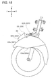
- the left front fender 223L is provided so as to be able to displace relative to the vehicle body frame 21 in accordance with the operation of the link mechanism 5. As illustrated in Fig. 17 , the left front fender 223L reduces the wind pressure received, during the traveling of the vehicle 1, by at least one of part of the power unit 25, part of the vehicle body cover 22, part of the vehicle body frame 21, part of the steering mechanism 7, and part of the link mechanism 5 any one of which is located between the left lower edge CDEL of the front portion 221 a of the front cover 221 and the upper edge WUEL of the left front wheel 32 as seen from front in the front-rear direction of the vehicle body frame 21 of the vehicle 1 under a condition that the vehicle body frame is in the upright state, and is located above the center CL in the up-down direction of the vehicle body frame 21 between the upper end WUL of the left front wheel 32 and the lower edge MDEL of the link mechanism 5 or the steering mechanism 7 lying directly above the left front wheel 32.
- the "left lower edge CDEL of the front portion 221 a of the front cover 221" denotes a contour portion of the front portion 221 a shown in Fig. 6 that extends from a portion intersecting an imaginary line denoting the front end CF to a portion intersecting an imaginary line denoting a rear end WBL of the left front wheel 32 by way of a lower end CD.
- the "upper edge WUEL of the left front wheel 32" denotes a contour portion that extends from a portion intersecting an imaginary line denoting a right end 32R of the left front wheel 32 to a portion intersecting an imaginary line denoting a left end 32L of the left wheel 32.
- Both imaginary lines shown in Fig. 17 are extending in the up-down direction of the vehicle body frame 21.
- the "lower edge MEDL of the link mechanism 5 or the steering mechanism 7 that lies directly above the left front wheel 32” denotes a contour portion of the link mechanism 5 or the steering mechanism 7 that appears between the imaginary line denoting the right end 32R of the left front wheel 32 and the left end 32L of the left front wheel 32 in Fig. 17 , and that faces the upper edge WUEL of the left front wheel 32.
- part of the left transmission plate 63 forms the lower edge MDEL. Any part that is included in the link mechanism 5 or the steering mechanism 7 and that is disposed in the related position can form the lower edge MDEL.
- the right front fender 223R is provided so as to be able to displace relative to the vehicle body frame 21 in accordance with the operation of the link mechanism 5. As illustrated in Fig. 17 , the right front fender 223R reduces the wind pressure received, during the traveling of the vehicle 1, by at least one of part of the power unit 25, part of the vehicle body cover 22, part of the vehicle body frame 21, part of the steering mechanism 7, and part of the link mechanism 5 any one of which is located between the right lower edge CDER of the front portion 221 a of the front cover 221 and the upper edge WUER of the right front wheel 31 as seen from front in the front-rear direction of the vehicle body frame 21 of the vehicle 1 under a condition that the vehicle body frame is in the upright state, and is located above the center CR in the up-down direction of the vehicle body frame 21 between the upper end WUR of the right front wheel 31 and the lower edge MDER of the link mechanism 5 or the steering mechanism 7 lying directly above the right front wheel 31.
- the "right lower edge CDER of the front portion 221 a of the front cover 221" denotes a contour portion of the front portion 221a shown in Fig. 6 that extends from a portion intersecting an imaginary line denoting the front end CF to a portion intersecting an imaginary line denoting a rear end WBR of the right front wheel 31 by way of a lower end CD.
- the "upper edge WUER of the right front wheel 31" denotes a contour portion that extends from a portion intersecting an imaginary line denoting a right end 31 R of the right front wheel 31 to a portion intersecting an imaginary line denoting a left end 31 L of the right wheel 31.
- Both imaginary lines shown in Fig. 17 are extending in the up-down direction of the vehicle body frame 21.
- the "lower edge MEDR of the link mechanism 5 or the steering mechanism 7 that lies in the upper side of the right front wheel 31” denotes a contour portion of the link mechanism 5 or the steering mechanism 7 that appears between the imaginary line denoting the right end 31 R of the right front wheel 31 and the left end 31 L of the right front wheel 31 in Fig. 17 , and that faces the upper edge WUER of the right front wheel 31.
- part of the right transmission plate 62 forms the lower edge MDER. Any part that is included in the link mechanism 5 or the steering mechanism 7 and that is disposed in the related position can form the lower edge MDER.
- a behind-front-wheels area S As shown in Fig. 5 , as seen from front in the front-rear direction of the vehicle body frame 21, an area lying directly above the right front wheel 31 and the left front wheel 32 and lying behind the right front wheel 31 and the left front wheel 32 is referred to as a behind-front-wheels area S.
- a right upper portion and a left upper portion of the leg shield 225 as seen from front in the front-rear direction of the vehicle body frame 21 corresponds to the behind-front-wheels area S.
- the behind-front-wheels area S is each of portions lying directly above the right front wheel 31 and the left front wheel 32 as seen from front in the front-rear direction of the vehicle body frame 21 while lying behind the right front wheel 31 and the left front wheel 32.
- the right front fender 223R and the left front fender 223L reduce wind pressure that the behind-front-wheels area S receives when the vehicle 1 goes straight ahead.
- Fig. 14 is a side view wherein the front portion of the vehicle 1 according to the embodiment is seen from the sideways of the vehicle body frame 21.
- Fig. 14 is a side view wherein the front portion of a vehicle 1001 according to a comparison example is seen from the same direction.
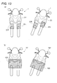
- Fig. 15 is a front view wherein the front portion of the vehicle 1 according to the embodiment is seen from front of the vehicle body frame 21.
- Fig. 15 is a front view wherein the front portion of the vehicle 1 according to the embodiment is seen from front of the vehicle body frame 21.
- FIG. 15 is a front view wherein the front portion of the vehicle 1001 according to the comparison example is seen from the same direction.
- Fig. 16 is a plan view wherein the front portion of the vehicle 1 according to the embodiment is seen from above of the vehicle body frame 21.
- Fig. 16 is a plan view wherein the front portion of the vehicle 1001 according to the comparison example is seen from the same direction. In any one of those drawings, the vehicle body frame is in the upright state.
- the right front wheel and the left front wheel each have a wide movable range. This is because the right front wheel and the left front wheel are turned when steered, are displaced in the up-down direction of the vehicle body frame as the right shock absorber and the left shock absorber extend or contract, and are displaced in the up-down direction of the vehicle body frame in accordance with the operation of the link mechanism.
- a vehicle body cover that is provided so as not to be able to displace relative to the vehicle body frame, needs to ensure a long distance with respect to the right front wheel and the left front wheel, each of which has such a wide movable range, so as to avoid the interference therewith.
- the vehicle body cover When a front end of the vehicle body cover is disposed behind the respective front ends of the right and left front wheels arranged with a narrowed interval so as to decrease the size of the vehicle body cover in the front-rear direction of the vehicle body frame, the vehicle body cover is likely to interfere with the right and left front wheels. It is necessary to secure a large distance between a lower edge of the front portion of the vehicle body cover and each of the respective upper ends of the right and left front wheels so as to prevent interference between the vehicle body cover and the right and left front wheels.
- the deterioration of the traveling performance is caused by wind pressure received, during the traveling of the vehicle, by at least one of part of the power unit, part of the vehicle body cover, part of the vehicle body frame, part of the steering mechanism, and part of the link mechanism located between the right lower edge of the front portion of the link cover part and the upper edge of the right front wheel and between the left lower edge of the front portion of the link cover part and the upper edge of the left front wheel as seen from front in the front-rear direction of the vehicle body frame of the vehicle under a condition that the vehicle body frame is in the upright state; located above the center in the up-down direction of the vehicle body frame between the upper end of the right front wheel and the lower edge of the link mechanism or the steering mechanism lying directly above the right front wheel; and located above the center in the up-down direction of the vehicle body frame between the upper end of the left front wheel and the lower edge of the link mechanism or the steering mechanism lying directly above the left front wheel. It has been found that the deterioration of the traveling performance is caused by wind pressure received, during the
- the vehicle body cover not only serves to cover at least part of the link mechanism but also serves to reduce wind pressure. Accordingly, the vehicle body cover is divided in accordance with the functions thereof into the part (the link cover part) that essentially serves to cover at least part of the link mechanism and the part (the right aerodynamic part and the left aerodynamic part) that serves to contribute to the wind pressure reduction. Then it has been considered suitable position and shape for each of the individual functional parts.
- the right front wheel and the left front wheel each have a wide movable range. Consequently, there may be largely changed the positions and sizes of the areas between the link mechanism and the right front wheel and between the link mechanism and the left front wheel, in accordance with the operation of the link mechanism.
- the aerodynamic part needs to be provided so as to cover the whole of the areas 1223 that change so largely to whereby deflect air flow incoming to the areas. This enlarges the vehicle body cover.
- the front cover 221 which is one example of a link cover part provided on the vehicle 1 according to the invention, is provided so as not to be able to displace relative to the vehicle body frame 21 and covers at least part of the link mechanism 5.
- the front cover 221 at least part of the function to contribute to the wind pressure reduction is divided into the aerodynamic part.
- the degree of freedom in design of the front cover 221 can be enhanced.
- the front cover 221 can be formed smaller.
- the front cover 221 has the front portion 221a that is disposed ahead of the respective rear ends WBR, WBL of the right front wheel 31 and the left front wheel 32 in the front-rear direction of the vehicle body frame 21.
- the right lower edge CDER of the front portion 221 a that lies directly above the right front wheel 31 is disposed above the lower end of the link mechanism 5 or the steering mechanism 7 in the up-down direction of the vehicle body frame 21
- the left lower edge CDEL of the front portion 221a that lies directly above the left front wheel 32 is disposed above the lower end of the link mechanism 5 or the steering mechanism 7 in the up-down direction of the vehicle body frame 21.
- the vehicle body cover 22 is made smaller in size in relation to the left-right direction of the vehicle body frame 21 by narrowing the space between the right front wheel 31 and the left front wheel 32.
- the vehicle body cover 22 is also made smaller in size in relation to the front-rear direction of the vehicle body frame 21.
- the vehicle 1 comprises the right front fender 223R and the left front fender 223L are provided so as to be able to displace relative to the vehicle body frame 21 in accordance with the operation of the link mechanism 5. Namely, as shown in (a) of Fig.
- the right front fender 223R (one example of the right aerodynamic part) and the left front fender 223L (one example of the left aerodynamic part) can be made smaller in size, even though the right front fender 223R and the left front fender 223L are given the same function of wind pressure reduction as that of the aerodynamic part that is provided so as not to be able to displace relative to the vehicle body frame 21 irrespective of how the link mechanism 5 operates.
- the right front fender 223R and the left front fender 223L are made smaller in size, it is possible to restrict increase of the wind pressure that the vehicle 1 receives. In addition, it is possible to reduce air resistance in the behind-front-wheels area S.
- the front cover 221 can be formed smaller in size by separating therefrom at least part of the function to contribute to the wind pressure reduction.
- the right front fender 223R and the left front fender 223L which have the function contributing to the wind pressure reduction can be formed smaller by providing the right front fender 223R and the left front fender 223L so as to able to displace relative to the vehicle body frame 21 in accordance with the operation of the link mechanism 5. Consequently, the front portion of the vehicle 1 can be made smaller in size while maintaining the traveling performance of the vehicle 1 comprising the leanable vehicle body frame 21 and the two front wheels 3.
- a front edge 223eL of the left front fender 223L is slanted so that at least either of an upper end 223fL and a lower end 223gL is positioned behind a front end 223hL.
- a front edge 223eR of the right front fender 223R is slanted so that at least either of an upper end 223fR and a lower end 223gR is positioned behind a front end 223hR.
- the "front edge 223eL of the left front fender 223L” denotes a contour portion that extends from the upper end 223fL to the lower end 223gL.
- the contour portion appears in an area lying ahead of the vehicle body frame 21.
- the "front edge 223eR of the right front fender 223R” denotes a contour portion that extends from the upper end 223fR to the lower end 223gR.
- the contour portion appears in an area lying ahead of the vehicle body frame 21.
- the front edge 223eR of the right front fender 223R is slanted so that at least either of a right end 223iR and a left end 223jR is positioned behind the front end 223hR.
- a front edge 223eL of the left front fender 223L is slanted so that at least either of a right end 223iL and a left end 223jL is positioned behind a front end 223hR.
- the "front edge 223eL of the left front fender 223L” denotes a contour portion that extends from the right end 223iL to the left end 223jL.
- the contour portion appears in an area lying ahead of the vehicle body frame 21.
- the "front edge 223eR of the right front fender 223R” denotes a contour portion that extends from the right end 223iR to the left end 223jR.
- the contour portion appears in an area lying ahead of the vehicle body frame 21.
- At least part of the right front fender 223R is disposed behind the front end WFR of the right front wheel 31 in the front-rear direction of the vehicle body frame 21 under a condition that the vehicle body frame 21 is in the upright state.
- at least part of the left front fender 223L is disposed behind the front end WFL of the left front wheel 32 in the front-rear direction of the vehicle body frame 21 under a condition that the vehicle body frame 21 is in the upright state.
- the right front wheel 31 and the right front fender 223R can be made closer to each other while avoiding the interference of the displacing right front wheel 31 with the right front fender 223R. Accordingly, the vehicle 1 equipped with the right front fender 223R having the function contributing to reduce wind pressure can be made smaller in size.
- the left front wheel 32 and the left front fender 223L can be made closer to each other while avoiding the interference of the displacing left front wheel 32 with the left front fender 223L. Accordingly, the vehicle 1 equipped with the left front fender 223L having the function contributing to reduce wind pressure can be made smaller in size.
- At least part of the right front fender 223R is disposed ahead of at least one of part of the power unit 25, part of the vehicle body cover 22, part of the vehicle body frame 21, part of the steering mechanism 7, and part of the link mechanism 5 any one of which is located between the right lower edge CDER of the front portion 221 a of the front cover 221 and the upper edge WUER of the right front wheel 31 as seen from front in the front-rear direction of the vehicle body frame 21 of the vehicle 1 under a condition that the vehicle body frame 21 is in the upright state, and is located above the center CR in the up-down direction of the vehicle body frame 21 between the upper end WUR of the right front wheel 31 and the lower edge MDER of the link mechanism 5 or the steering mechanism 7 lying directly above the right front wheel 31.
- At least part of the left front fender 223L is disposed ahead of at least one of part of the power unit 25, part of the vehicle body cover 22, part of the vehicle body frame 21, part of the steering mechanism 7, and part of the link mechanism 5 any one of which is located between the left lower edge CDEL of the front portion 221 a of the front cover 221 and the upper edge WUEL of the left front wheel 32 as seen from front in the front-rear direction of the vehicle body frame 21 of the vehicle 1 under a condition that the vehicle body frame 21 is in the upright state, and is located above the center CL in the up-down direction of the vehicle body frame 21 between the upper end WUL of the left front wheel 32 and the lower edge MDEL of the link mechanism 5 or the steering mechanism 7 lying directly above the left front wheel 32.
- the right front wheel 31 and the right front fender 223R can be made closer to each other while avoiding the interference of the displacing right front wheel 31 with the right front fender 223R. Accordingly, the vehicle 1 equipped with the right front fender 223R having the function contributing to reduce wind pressure can be made smaller in size.
- the left front wheel 32 and the left front fender 223L can be made closer to each other while avoiding the interference of the displacing left front wheel 32 with the left front fender 223L. Accordingly, the vehicle 1 equipped with the left front fender 223L having the function contributing to reduce wind pressure can be made smaller in size.
- At least part of the right front fender 223R is disposed above a center CR in the up-down direction of the vehicle body frame 21 between the upper end WUR of the right front wheel 31 and a right lower edge MDER of the link mechanism 5 or the steering mechanism 7 that lies directly above the right front wheel 31, and is disposed below a right lower edge CEDR of the front portion 221a of the front cover 221.
- At least part of the left front fender 223L is disposed above a center CL in the up-down direction of the vehicle body frame 21 between the upper end WUL of the left front wheel 32 and a left lower edge MDEL of the link mechanism 5 or the steering mechanism 7 that lies directly above the left front wheel 32, and is disposed below a left lower edge CEDL of the front portion 221 a of the front cover 221.
- At least part of the right front fender 223R is disposed below the center CR in the up-down direction of the vehicle body frame 21 between the upper end WUR of the right front wheel 31 and the lower edge MDER of the link mechanism 5 or the steering mechanism 7 that lies directly above the right front wheel 31, and is disposed above the upper edge WUER of the right front wheel 31.
- At least part of the left front fender 223L is disposed below the center CL in the up-down direction of the vehicle body frame 21 between the upper end WUL of the left front wheel 32 and the lower edge MDEL of the link mechanism 5 or the steering mechanism 7 that lies directly above the left front wheel 32, and is disposed above the upper edge WUEL of the left front wheel 32.
- At least part of the right front fender 223R is disposed below the center CR in the up-down direction of the vehicle body frame 21 between the upper end WUR of the right front wheel 31 and the lower edge MEDR of the link mechanism 5 or the steering mechanism 7 that lies directly above the right front wheel 31, and is disposed upward than the upper edge WUER of the right front wheel 31.
- the right front fender 223R that is provided so as to be able to displace relative to the vehicle body frame is disposed both above and below the center CR, the function contributing to the wind pressure reduction can be ensured even though the right front fender223R is made small.
- the portion lying below the center CR is spaced farther away from the front cover 221 that is provided so as not to be able to displace relative to the vehicle body frame 21 than the portion lying above the center CR. Accordingly, even though part of the right front fender 223R is disposed below the center CR, the interference of the right front fender 223R with the front cover 221 can be avoided.
- At least part of the left front fender 223L is disposed below the center CL in the up-down direction of the vehicle body frame 21 between the upper end WUL of the left front wheel 32 and the lower edge MDEL of the link mechanism 5 or the steering mechanism 7 that lies directly above the left front wheel 32, and is disposed above the upper edge WUEL of the left front wheel 32.
- the left front fender 223L that is provided so as to be able to displace relative to the vehicle body frame 21 is disposed both above and below the center CL, the function contributing to the wind pressure reduction can be ensured even though the left front fender223L is made small.
- the portion lying below the center CL is spaced farther away from the front cover 221 that is provided so as not to be able to displace relative to the vehicle body frame 21 than the portion lying upwards than the center CL. Accordingly, even though part of the left front fender 223L is disposed below the center CL, the interference of the left front fender 223L with the front cover 221 can be avoided.
- the right front fender 223R has at least part of a fender function to cover at least part of an upper face of the right front wheel 31 and to restrict the scattering of muddy water or the like that is raised by the right front wheel 31.
- the left front fender 223L has at least part of a fender function to cover at least part of an upper face of the left front wheel 32 and to restrict the scattering of muddy water or the like that is raised by the left front wheel 32.
- the right front fender 223R having the function contributing to reduce wind pressure can be made smaller in size.
- part of the fender function for the right front wheel 31 is assigned to the right front fender 223R, it is possible to enhance the degree of freedom in the design of the right aerodynamic part and the right front fender.
- part of the function of the right aerodynamic part is assigned to the right front fender of the right front wheel, it is possible to enhance the degree of freedom in the design of the right aerodynamic part and the right front fender. Accordingly, compared with a case where individual parts are prepared for each of the functions, the overall configuration can be made smaller while ensuring the same functions.
- the left front fender 223L having the function contributing to reduce wind pressure can be made smaller in size. Since a part of a fender function for the left front wheel 32 is assigned to the left front fender 223L, it is possible to enhance the degree of freedom in the design of the left aerodynamic portion and the left front fender. Moreover, since part of the function of the left aerodynamic part is assigned to the left front fender of the left front wheel, it is possible to enhance the degree of freedom in the design of the left aerodynamic part and the left front fender. Accordingly, compared with a case where individual parts are prepared for each of the functions, the overall configuration can be made smaller while ensuring the same functions.
- the right front fender 223R and the left front fender 223L are fixed to the right bracket 317 and the left bracket 327, respectively.
- the right front fender 223R and the left front fender 223L are moved directly in accordance with the operation of the link mechanism 5, the right front fender 223R and the left front fender 223L are easy to be made small in size. Accordingly, it is possible to decrease the size of the front portion of the vehicle 1 while maintaining traveling performance of the vehicle 1 comprising the leanable vehicle body frame 21 and the two front wheels 3.
- the part serving as the right aerodynamic part may be fixed to a portion other than the right bracket 317 as long as it is possible to reduce the wind pressure received, during the traveling of the vehicle 1, by at least one of part of the power unit 25, part of the vehicle body cover 22, part of the vehicle body frame 21, part of the steering mechanism 7, and part of the link mechanism 5 any one of which is located between the right lower edge CDER of the front portion 221 a of the front cover 221 and the upper edge WUER of the right front wheel 31 as seen from front in the front-rear direction of the vehicle body frame 21 of the vehicle 1 under a condition that the vehicle body frame 21 is in the upright state, and is located above the center CR in the up-down direction of the vehicle body frame 21 between the upper end WUR of the right front wheel 31 and the lower edge MDER of the link mechanism 5 or the steering mechanism 7 lying directly above the right front wheel 31.
- the portion serving as the right aerodynamic part may be fixed to any one of a right shock absorber 33 and a steering force transmission mechanism 6.
- the steering force transmission mechanism 6 includes the middle transmission plate 61, the right transmission plate 62, the middle joint 64, the right joint 65, and the tie rod 67.
- the part serving as the left aerodynamic part may be fixed to a portion other than the left bracket 327 as long as it is possible to reduce the wind pressure received, during the traveling of the vehicle 1, by at least one of part of the power unit 25, part of the vehicle body cover 22, part of the vehicle body frame 21, part of the steering mechanism 7, and part of the link mechanism 5 any one of which is located between the left lower edge CDEL of the front portion 221 a of the front cover 221 and the upper edge WUEL of the left front wheel 32 as seen from front in the front-rear direction of the vehicle body frame 21 of the vehicle 1 under a condition that the vehicle body frame 21 is in the upright state, and is located above the center CL in the up-down direction of the vehicle body frame 21 between the upper end WUL of the left front wheel 32 and the lower edge MDEL of the link mechanism 5 or the steering mechanism 7 lying directly above the left front wheel 32.
- the portion serving as the left aerodynamic part may be fixed to any one of a left shock absorber 35 and the steering force transmission mechanism 6.
- the steering force transmission mechanism 6 includes the middle transmission plate 61, the left transmission plate 63, the middle joint 64, the left joint 66, and the tie rod 67.
- a right front fender 223R and a left front fender 223L are fixed to upper portions of left and right shock absorbers, respectively.
- a left shock absorber 35A includes a left outer tube 322A (one example of the upper portion of the left shock absorber) and a left inner tube 326A (one example of the lower portion of the left shock absorber).
- An upper portion of the left outer tube 322A is fixed to a left bracket 327.
- the left inner tube 326A is disposed directly below the left outer tube 322A under a condition that part of the left inner tube 326A is inserted in the left outer tube 322A.
- the left inner tube 326A supports a left front wheel 32.
- the left front fender 223L has a portion that extends rightward in a left-right direction of a vehicle body frame 21 than the left front wheel 32, as seen from front of the vehicle 1 under a condition that the vehicle body frame 21 is in the upright state.
- the left front fender 223L is fixed to the left outer tube 322A.
- a right shock absorber 33A according to the modified example has a configuration that is symmetrical with that of the left shock absorber 35A in relation to the left-right direction.
- the right shock absorber 33A according to the modified example includes a right outer tube 312A (one example of the upper portion of the right shock absorber) and a right inner tube 316A (one example of the lower portion of the right shock absorber).
- An upper portion of the right outer tube 312A is fixed to a right bracket 317.
- the right inner tube 316A is disposed directly below the right outer tube 312A under a condition that part of the right inner tube 316A is inserted in the right outer tube 312A.
- the right inner tube 316A supports a right front wheel 31.
- the right front fender 223R has a configuration that is symmetrical with that of the left front fender 223L in relation to the left-right direction. Namely, the right front fender 223R has a portion that extends leftward in the left-right direction of the vehicle body frame 21 than the right front wheel 31, as seen from front of the vehicle 1 under a condition that the vehicle body frame 21 is in the upright state.
- the right front fender 223R is fixed to the right outer tube 312A.
- the left front fender 223L is not displaced in the same direction in accordance with the displacement of the left front wheel 32.
- the shape of the right front fender 223R may be appropriately selected as long as it is possible to reduce wind pressure received, during the traveling of the vehicle 1, by at least one of part of the power unit 25, part of the vehicle body cover 22, part of the vehicle body frame 21, part of the steering mechanism 7, and part of the link mechanism 5 any one of which is located between the right lower edge CDER of the front portion 221 a of the front cover 221 and the upper edge WUER of the right front wheel 31 as seen from front in the front-rear direction of the vehicle body frame 21 of the vehicle 1 under a condition that the vehicle body frame is in the upright state, and is located above the center CR in the up-down direction of the vehicle body frame 21 between the upper end WUR of the right front wheel 31 and the lower edge MDER of the link mechanism 5 or the steering mechanism 7 lying directly above the right front wheel 31.
- the shape of the left front fender 223L may be appropriately selected as long as it is possible to reduce wind pressure received, during the traveling of the vehicle 1, by at least one of part of the power unit 25, part of the vehicle body cover 22, part of the vehicle body frame 21, part of the steering mechanism 7, and part of the link mechanism 5 any one of which is located between the left lower edge CDEL of the front portion 221 a of the front cover 221 and the upper edge WUEL of the left front wheel 32 as seen from front in the front-rear direction of the vehicle body frame 21 of the vehicle 1 under a condition that the vehicle body frame is in the upright state, and is located above the center CL in the up-down direction of the vehicle body frame 21 between the upper end WUL of the left front wheel 32 and the lower edge MDEL of the link mechanism 5 or the steering mechanism 7 lying directly above the left front wheel 32.
- FIGs. 9 and 10 are front views that schematically show part of the configuration of the modified example
- Fig. 9 is a front view wherein the configuration is seen from front in a front-rear direction of the vehicle body frame 21.
- Fig. 9 is a left side view wherein the configuration is seen from left in a left-right direction of the vehicle body frame 21.
- Fig. 9 is a plan view wherein a right front fender 223R and a left front fender 223L according this modified example are seen from above in the up-down direction of the vehicle body frame 21.
- the right front fender 223R has a first right projecting portion 223dR that extends leftward in the left-right direction of the vehicle body frame 21 than a right front wheel 31, and has a second projecting portion 223kR that extends upward in the up-down direction of the vehicle body frame 21 than the right front wheel 31, as seen from front of the vehicle 1 under a condition that the vehicle body frame 21 is in the upright state.
- the left front fender 223L has a first left projecting portion 223dL that extends rightward in the left-right direction of the vehicle body frame 21 than a left front wheel 32, and has a second projecting portion 223kL that extends upward in the up-down direction of the vehicle body frame 21 than the left front wheel 32, as seen from front of the vehicle 1 under a condition that the vehicle body frame 21 is in the upright state.
- the first right projecting portion 223dR, the second right projecting portion 223kR, the first left projecting portion 223dL, and the second left projecting portion 223kL are provided so as to be able to displace relative to the vehicle body frame 21 in accordance with the operation of a steering mechanism 7.
- a steering mechanism 7 As shown in Fig. 7 , when the rider operates the handlebar 23, via the steering force transmission mechanism 6, the right bracket 317 and the left bracket 327 are turned relative to the right side member 53 and the left side member 54 about the right center axis X and the left center axis Y, respectively.
- the link mechanism 5 when the rider causes the vehicle 1 to lean leftward, the link mechanism 5 operates.
- the positions of the right bracket 317 and the left bracket 327 relative to the vehicle body frame 21 are changed in the up-down direction of the vehicle body frame 21 in accordance with the operation of the link mechanism 5.
- This causes the right front fender 223R and the left front fender 223L that are fixed to the right bracket 317 and the left bracket 327, respectively, to change their relative positions to the vehicle body frame 21 in the up-down direction of the vehicle body frame 21.
- first right projecting portion 223dR, the second right projecting portion 223kR, the first left projecting portion 223dL, and the second left projecting portion 223kL are provided so as to be able to displace relative to the vehicle body frame 21 in accordance with the operation of the link mechanism 5.
- the first right projecting portion 223dR and the second left projecting portion 223dL are disposed and shaped so that the first right projecting portion 223dR and the first left projecting portion 223dL are prevented from interfering with each other even though the first right projecting portion 223dR and the first left projecting portion 223dL are displaced relative to the vehicle body frame 21 according to the steering operation and the leaning operation that are described above.
- the right front fender 223R may be fixed to a right outer tube 312 (one example of the lower portion of the right shock absorber) of a right shock absorber 33.
- the left front fender 223L may be fixed to a left outer tube 322 (one example of the lower portion of the left shock absorber) of a left shock absorber 35.
- the right front fender 223R can also be displaced relative to the vehicle body frame 21 by being displaced in the same direction as a right shock absorber 33 extends or contract.
- the left front fender 223L can also be displaced relative to the vehicle body frame 21 by being displaced in the same direction as a left shock absorber 35 extends or contract.
- the left front fender 223L may be formed integrally with the left bracket 327.
- the right front fender 223R according to this modified example may be formed integrally with the right bracket 317.
- the "parallel” line also includes two straight lines which do not intersect each other as members while they are inclined within the range of ⁇ 40 degrees.
- the term “along” also includes a case where the direction and the member are inclined within the range of ⁇ 40 degrees.
- the term “extend” also includes a case where the direction is inclined within the range of ⁇ 40 degrees.
- the vehicle according to the invention is a vehicle comprising a leanable vehicle body frame and two front wheels.
- the number of rear wheels is not limited to one, and may be two.
- a center in the left-right direction of the vehicle body frame 21 of the rear wheel 4 coincides with a center in the left-right direction of the vehicle body frame 21 of the space defined between the right front wheel 31 and the left front wheel 32.
- the center in the left-right direction of the vehicle body frame 21 of the rear wheel 4 does not have to coincide with the center in the left-right direction of the vehicle body frame 21 of the space defined between the right front wheel 31 and the left front wheel 32.
- the link mechanism 5 may further include a cross member other than the upper cross member 51 and the lower cross member 52.
- the "upper cross member” and the “lower cross member” are merely so called based on their relative positions in the up-down direction.
- the upper cross member is not necessarily an uppermost cross member of the link mechanism 5.
- the upper cross member means a cross member that lies above another cross member that lies below.
- the lower cross member is not necessarily a lowermost cross member of the link mechanism 5.
- the lower cross member means a cross member that lies below another cross member that lies above.
- At least one of the upper cross member 51 and the lower cross member 52 may be made up of two parts such as a right cross member and a left cross member. In this way, the upper cross member 51 and the lower cross member 52 may be made up of a plurality of cross members, as long as the linkage function is realized.
- the portion that serves as the right aerodynamic part does not have to be the right front fender 223R that is included in the vehicle body cover 22.
- the right aerodynamic part may be made up of a plurality of rods or a group of fins, as long as it is possible to ensure the function for reducing the wind pressure received, during the traveling of the vehicle 1, by at least one of part of the power unit 25, part of the vehicle body cover 22, part of the vehicle body frame 21, part of the steering mechanism 7, and part of the link mechanism 5 any one of which is located between the right lower edge CDER of the front portion 221 a of the front cover 221 and the upper edge WU ER of the right front wheel 31 as seen from front in the front-rear direction of the vehicle body frame 21 of the vehicle 1 under a condition that the vehicle body frame 21 is in the upright state, and is located above the center CR in the up-down direction of the vehicle body frame 21 between the upper end WUR of the right front wheel 31 and the lower edge MDER of the link mechanism 5 or the steering mechanism 7 lying directly above the
- the portion that serves as the left aerodynamic part does not have to be the left front fender 223L that is included in the vehicle body cover 22.
- the left aerodynamic part may be made up of a plurality of rods or a group of fins, as long as it is possible to ensure the function for reducing the wind pressure received, during the traveling of the vehicle 1, by at least one of part of the power unit 25, part of the vehicle body cover 22, part of the vehicle body frame 21, part of the steering mechanism 7, and part of the link mechanism 5 any one of which is located between the left lower edge CDEL of the front portion 221 a of the front cover 221 and the upper edge WU EL of the left front wheel 32 as seen from front in the front-rear direction of the vehicle body frame 21 of the vehicle 1 under a condition that the vehicle body frame is in the upright state, and is located above the center CL in the up-down direction of the vehicle body frame 21 between the upper end WUL of the left front wheel 32 and the lower edge MDEL of the link mechanism 5 or the steering mechanism 7 lying directly above the left front
- the material forming the left aerodynamic part is not limited to resins but metals or the like may be used.
Landscapes
- Engineering & Computer Science (AREA)
- Mechanical Engineering (AREA)
- Chemical & Material Sciences (AREA)
- Combustion & Propulsion (AREA)
- Transportation (AREA)
- Automatic Cycles, And Cycles In General (AREA)
- Body Structure For Vehicles (AREA)
- Steering-Linkage Mechanisms And Four-Wheel Steering (AREA)
Applications Claiming Priority (3)
| Application Number | Priority Date | Filing Date | Title |
|---|---|---|---|
| JP2012276256 | 2012-12-18 | ||
| JP2013138485 | 2013-07-01 | ||
| PCT/JP2013/083931 WO2014098140A1 (fr) | 2012-12-18 | 2013-12-18 | Véhicule |
Publications (3)
| Publication Number | Publication Date |
|---|---|
| EP2937270A1 true EP2937270A1 (fr) | 2015-10-28 |
| EP2937270A4 EP2937270A4 (fr) | 2016-01-06 |
| EP2937270B1 EP2937270B1 (fr) | 2018-08-22 |
Family
ID=50978460
Family Applications (1)
| Application Number | Title | Priority Date | Filing Date |
|---|---|---|---|
| EP13865194.8A Active EP2937270B1 (fr) | 2012-12-18 | 2013-12-18 | Véhicule |
Country Status (9)
| Country | Link |
|---|---|
| US (1) | US9452803B2 (fr) |
| EP (1) | EP2937270B1 (fr) |
| JP (1) | JP5595623B1 (fr) |
| CN (1) | CN104520177B (fr) |
| BR (1) | BR112015014091A2 (fr) |
| ES (1) | ES2698961T3 (fr) |
| MX (1) | MX342132B (fr) |
| TW (1) | TWI523790B (fr) |
| WO (1) | WO2014098140A1 (fr) |
Cited By (1)
| Publication number | Priority date | Publication date | Assignee | Title |
|---|---|---|---|---|
| EP2982588A4 (fr) * | 2014-01-31 | 2016-06-22 | Yamaha Motor Co Ltd | Véhicule |
Families Citing this family (25)
| Publication number | Priority date | Publication date | Assignee | Title |
|---|---|---|---|---|
| BR112015014672B1 (pt) * | 2012-12-19 | 2021-07-06 | Yamaha Hatsudoki Kabushiki Kaisha | veículo que é acionado por energia a partir de uma fonte de energia |
| MX2015017478A (es) * | 2013-07-01 | 2016-03-21 | Yamaha Motor Co Ltd | Vehiculo. |
| ES2621334T3 (es) * | 2013-10-31 | 2017-07-03 | Yamaha Hatsudoki Kabushiki Kaisha | Sistema de freno y vehículo |
| JP6057939B2 (ja) * | 2014-03-28 | 2017-01-11 | 本田技研工業株式会社 | 鞍乗り型車両の車体フレームの製造方法 |
| JP6122921B2 (ja) | 2015-08-31 | 2017-04-26 | 本田技研工業株式会社 | 鞍乗り型車両 |
| JP2017065534A (ja) * | 2015-09-30 | 2017-04-06 | ヤマハ発動機株式会社 | 車両 |
| JP2017065526A (ja) * | 2015-09-30 | 2017-04-06 | ヤマハ発動機株式会社 | 車両 |
| JP2017065532A (ja) * | 2015-09-30 | 2017-04-06 | ヤマハ発動機株式会社 | 車両 |
| JP2017065529A (ja) * | 2015-09-30 | 2017-04-06 | ヤマハ発動機株式会社 | 車両 |
| ITUB20159478A1 (it) * | 2015-12-28 | 2017-06-28 | Piaggio & C Spa | Avantreno di motoveicolo tiltante e relativo motoveicolo tiltante |
| CN108495780B (zh) * | 2016-01-22 | 2021-02-02 | 庞巴迪动力产品公司 | 用于轮式车辆的挡泥板 |
| USD819498S1 (en) * | 2017-01-03 | 2018-06-05 | Zhejiang Doohan Technology Co., Ltd. | Reverse trike vehicle |
| JP2018144697A (ja) * | 2017-03-07 | 2018-09-20 | ヤマハ発動機株式会社 | 車両 |
| JP2018144698A (ja) * | 2017-03-07 | 2018-09-20 | ヤマハ発動機株式会社 | 車両 |
| USD849601S1 (en) * | 2017-10-06 | 2019-05-28 | Zhejiang Doohan Technology Co., Ltd. | Three-wheeled motorcycle |
| JP2019077368A (ja) | 2017-10-25 | 2019-05-23 | ヤマハ発動機株式会社 | リーン車両 |
| TWD197633S (zh) * | 2017-11-06 | 2019-05-21 | 瑞士商快德洛車輛股份公司 | 摩托車 |
| TWI768390B (zh) * | 2019-07-01 | 2022-06-21 | 日商山葉發動機股份有限公司 | 傾斜車輛 |
| WO2021039991A1 (fr) * | 2019-08-30 | 2021-03-04 | ヤマハ発動機株式会社 | Véhicule inclinable |
| WO2021039989A1 (fr) | 2019-08-30 | 2021-03-04 | ヤマハ発動機株式会社 | Véhicule inclinable |
| CN111169575A (zh) * | 2020-03-09 | 2020-05-19 | 吕榕志 | 外挂接驳的非独立悬架机构 |
| CN111137389A (zh) * | 2020-03-09 | 2020-05-12 | 吕榕志 | 平行四边形轴对称上下运动变形自回正平衡优化机构 |
| CN111114679A (zh) * | 2020-03-09 | 2020-05-08 | 吕榕志 | 倒三轮的前双轮自回正平衡总成可变外形优化装置 |
| CN111169576A (zh) * | 2020-03-11 | 2020-05-19 | 吕榕志 | 外挂接驳的非独立悬架倒三轮前双轮可变外形优化系统 |
| CN112124475A (zh) * | 2020-03-23 | 2020-12-25 | 吕榕志 | 倒三轮的方向把自回正装置 |
Family Cites Families (21)
| Publication number | Priority date | Publication date | Assignee | Title |
|---|---|---|---|---|
| US4351410A (en) | 1980-07-17 | 1982-09-28 | Townsend Engineering Company | Self-balancing wheeled vehicle |
| JPS60110187U (ja) | 1983-12-29 | 1985-07-26 | 本田技研工業株式会社 | 自動二輪車のフロントフエンダ− |
| JPH07144671A (ja) | 1993-11-25 | 1995-06-06 | Suzuki Motor Corp | 自動二輪車のフロントフエンダ |
| JP2002337779A (ja) | 2001-05-21 | 2002-11-27 | Abanteku:Kk | 三輪車 |
| ITMI20031108A1 (it) | 2003-06-03 | 2004-12-04 | Piaggio & C Spa | Veicolo rollante a tre ruote con due ruote anteriori sterzanti |
| US7143853B1 (en) * | 2004-02-18 | 2006-12-05 | Bombardier Recreational Products Inc. | Roll-related reactive system |
| FR2872773B1 (fr) * | 2004-07-07 | 2006-09-29 | Moulene Sarl | Vehicule motorise de faible largeur |
| USD547242S1 (en) | 2006-03-02 | 2007-07-24 | Piaggio & C. S.P.A. | Motorcycle |
| JP2009161015A (ja) | 2007-12-28 | 2009-07-23 | Yamaha Motor Co Ltd | 自動二輪車のフロントフェンダ、及び自動二輪車 |
| USD598328S1 (en) * | 2008-05-12 | 2009-08-18 | Piaggio & C. S.P.A. | Motorcycle |
| TW201117997A (en) * | 2009-11-27 | 2011-06-01 | Kwang Yang Motor Co | Anti-turnover device for vehicle having two front wheels |
| BR112012020513B1 (pt) | 2010-02-18 | 2019-09-10 | Honda Motor Co Ltd | veículo elétrico do tipo lambreta motorizado |
| EP2540600B1 (fr) | 2010-02-23 | 2020-07-01 | Honda Motor Co., Ltd. | Dispositif d'avertissement de l'approche d'un véhicule électrique chevauché |
| JP5528870B2 (ja) | 2010-03-23 | 2014-06-25 | 本田技研工業株式会社 | フロント2輪式鞍乗型車両 |
| IT1401130B1 (it) | 2010-07-16 | 2013-07-12 | Piaggio & C Spa | Sistema di sospensione per motoveicoli |
| JP2012056503A (ja) * | 2010-09-10 | 2012-03-22 | Nagaoka Techno Service:Kk | 車体をロールさせる車両 |
| USD656435S1 (en) | 2010-10-18 | 2012-03-27 | Piaggio & C. S.P.A. | Motor scooter |
| US8662228B2 (en) * | 2011-01-19 | 2014-03-04 | Green Lite Motors Corporation | Free-to-lean three-wheeled passenger vehicle, power plant controller and body therefor |
| MX339750B (es) * | 2012-12-18 | 2016-06-08 | Yamaha Motor Co Ltd | Vehiculo. |
| DE102014201668B4 (de) * | 2013-03-07 | 2021-09-02 | Ford Global Technologies, Llc | Seitlich neigbares, mehrspuriges Fahrzeug |
| JP5915625B2 (ja) * | 2013-11-15 | 2016-05-11 | トヨタ自動車株式会社 | 乗り物 |
-
2013
- 2013-12-18 US US14/652,871 patent/US9452803B2/en active Active
- 2013-12-18 TW TW102147104A patent/TWI523790B/zh active
- 2013-12-18 WO PCT/JP2013/083931 patent/WO2014098140A1/fr not_active Ceased
- 2013-12-18 EP EP13865194.8A patent/EP2937270B1/fr active Active
- 2013-12-18 BR BR112015014091A patent/BR112015014091A2/pt not_active IP Right Cessation
- 2013-12-18 ES ES13865194T patent/ES2698961T3/es active Active
- 2013-12-18 JP JP2014528715A patent/JP5595623B1/ja active Active
- 2013-12-18 MX MX2015007764A patent/MX342132B/es active IP Right Grant
- 2013-12-18 CN CN201380038938.6A patent/CN104520177B/zh active Active
Cited By (1)
| Publication number | Priority date | Publication date | Assignee | Title |
|---|---|---|---|---|
| EP2982588A4 (fr) * | 2014-01-31 | 2016-06-22 | Yamaha Motor Co Ltd | Véhicule |
Also Published As
| Publication number | Publication date |
|---|---|
| WO2014098140A1 (fr) | 2014-06-26 |
| TWI523790B (zh) | 2016-03-01 |
| TW201429787A (zh) | 2014-08-01 |
| CN104520177A (zh) | 2015-04-15 |
| US9452803B2 (en) | 2016-09-27 |
| US20150321721A1 (en) | 2015-11-12 |
| EP2937270B1 (fr) | 2018-08-22 |
| MX342132B (es) | 2016-09-14 |
| JP5595623B1 (ja) | 2014-09-24 |
| JPWO2014098140A1 (ja) | 2017-01-12 |
| EP2937270A4 (fr) | 2016-01-06 |
| BR112015014091A2 (pt) | 2017-07-11 |
| CN104520177B (zh) | 2017-12-26 |
| MX2015007764A (es) | 2015-09-04 |
| ES2698961T3 (es) | 2019-02-06 |
Similar Documents
| Publication | Publication Date | Title |
|---|---|---|
| EP2937270B1 (fr) | Véhicule | |
| EP2921388B1 (fr) | Véhicule | |
| EP3002186B1 (fr) | Véhicule | |
| US10179623B2 (en) | Vehicle | |
| EP2921384B1 (fr) | Véhicule | |
| US8607916B2 (en) | Vehicle shroud | |
| EP2921387B1 (fr) | Véhicule | |
| EP3805087B1 (fr) | Procédé de fabrication de châssis | |
| JP6883063B2 (ja) | 鞍乗り型車両 | |
| EP3006312B1 (fr) | Véhicule | |
| OA17615A (en) | Vehicle. | |
| OA17607A (en) | Vehicle. |
Legal Events
| Date | Code | Title | Description |
|---|---|---|---|
| PUAI | Public reference made under article 153(3) epc to a published international application that has entered the european phase |
Free format text: ORIGINAL CODE: 0009012 |
|
| 17P | Request for examination filed |
Effective date: 20150618 |
|
| AK | Designated contracting states |
Kind code of ref document: A1 Designated state(s): AL AT BE BG CH CY CZ DE DK EE ES FI FR GB GR HR HU IE IS IT LI LT LU LV MC MK MT NL NO PL PT RO RS SE SI SK SM TR |
|
| AX | Request for extension of the european patent |
Extension state: BA ME |
|
| REG | Reference to a national code |
Ref country code: DE Ref legal event code: R079 Ref document number: 602013042561 Country of ref document: DE Free format text: PREVIOUS MAIN CLASS: B62J0017000000 Ipc: B62K0005100000 |
|
| A4 | Supplementary search report drawn up and despatched |
Effective date: 20151203 |
|
| RIC1 | Information provided on ipc code assigned before grant |
Ipc: B62K 5/10 20130101AFI20151127BHEP Ipc: B62J 17/02 20060101ALI20151127BHEP Ipc: B62K 5/05 20130101ALI20151127BHEP Ipc: B62J 15/00 20060101ALI20151127BHEP Ipc: B62K 5/08 20060101ALI20151127BHEP Ipc: B62J 17/00 20060101ALI20151127BHEP Ipc: B62D 9/02 20060101ALI20151127BHEP Ipc: B62K 5/027 20130101ALI20151127BHEP |
|
| 17Q | First examination report despatched |
Effective date: 20151218 |
|
| DAX | Request for extension of the european patent (deleted) | ||
| GRAP | Despatch of communication of intention to grant a patent |
Free format text: ORIGINAL CODE: EPIDOSNIGR1 |
|
| INTG | Intention to grant announced |
Effective date: 20180328 |
|
| GRAS | Grant fee paid |
Free format text: ORIGINAL CODE: EPIDOSNIGR3 |
|
| GRAA | (expected) grant |
Free format text: ORIGINAL CODE: 0009210 |
|
| AK | Designated contracting states |
Kind code of ref document: B1 Designated state(s): AL AT BE BG CH CY CZ DE DK EE ES FI FR GB GR HR HU IE IS IT LI LT LU LV MC MK MT NL NO PL PT RO RS SE SI SK SM TR |
|
| REG | Reference to a national code |
Ref country code: GB Ref legal event code: FG4D |
|
| REG | Reference to a national code |
Ref country code: CH Ref legal event code: EP |
|
| REG | Reference to a national code |
Ref country code: AT Ref legal event code: REF Ref document number: 1032148 Country of ref document: AT Kind code of ref document: T Effective date: 20180915 |
|
| REG | Reference to a national code |
Ref country code: IE Ref legal event code: FG4D |
|
| REG | Reference to a national code |
Ref country code: DE Ref legal event code: R096 Ref document number: 602013042561 Country of ref document: DE |
|
| REG | Reference to a national code |
Ref country code: NL Ref legal event code: MP Effective date: 20180822 |
|
| REG | Reference to a national code |
Ref country code: LT Ref legal event code: MG4D |
|
| PG25 | Lapsed in a contracting state [announced via postgrant information from national office to epo] |
Ref country code: NO Free format text: LAPSE BECAUSE OF FAILURE TO SUBMIT A TRANSLATION OF THE DESCRIPTION OR TO PAY THE FEE WITHIN THE PRESCRIBED TIME-LIMIT Effective date: 20181122 Ref country code: GR Free format text: LAPSE BECAUSE OF FAILURE TO SUBMIT A TRANSLATION OF THE DESCRIPTION OR TO PAY THE FEE WITHIN THE PRESCRIBED TIME-LIMIT Effective date: 20181123 Ref country code: NL Free format text: LAPSE BECAUSE OF FAILURE TO SUBMIT A TRANSLATION OF THE DESCRIPTION OR TO PAY THE FEE WITHIN THE PRESCRIBED TIME-LIMIT Effective date: 20180822 Ref country code: IS Free format text: LAPSE BECAUSE OF FAILURE TO SUBMIT A TRANSLATION OF THE DESCRIPTION OR TO PAY THE FEE WITHIN THE PRESCRIBED TIME-LIMIT Effective date: 20181222 Ref country code: RS Free format text: LAPSE BECAUSE OF FAILURE TO SUBMIT A TRANSLATION OF THE DESCRIPTION OR TO PAY THE FEE WITHIN THE PRESCRIBED TIME-LIMIT Effective date: 20180822 Ref country code: BG Free format text: LAPSE BECAUSE OF FAILURE TO SUBMIT A TRANSLATION OF THE DESCRIPTION OR TO PAY THE FEE WITHIN THE PRESCRIBED TIME-LIMIT Effective date: 20181122 Ref country code: LT Free format text: LAPSE BECAUSE OF FAILURE TO SUBMIT A TRANSLATION OF THE DESCRIPTION OR TO PAY THE FEE WITHIN THE PRESCRIBED TIME-LIMIT Effective date: 20180822 Ref country code: FI Free format text: LAPSE BECAUSE OF FAILURE TO SUBMIT A TRANSLATION OF THE DESCRIPTION OR TO PAY THE FEE WITHIN THE PRESCRIBED TIME-LIMIT Effective date: 20180822 Ref country code: SE Free format text: LAPSE BECAUSE OF FAILURE TO SUBMIT A TRANSLATION OF THE DESCRIPTION OR TO PAY THE FEE WITHIN THE PRESCRIBED TIME-LIMIT Effective date: 20180822 |
|
| REG | Reference to a national code |
Ref country code: ES Ref legal event code: FG2A Ref document number: 2698961 Country of ref document: ES Kind code of ref document: T3 Effective date: 20190206 |
|
| REG | Reference to a national code |
Ref country code: AT Ref legal event code: MK05 Ref document number: 1032148 Country of ref document: AT Kind code of ref document: T Effective date: 20180822 |
|
| PG25 | Lapsed in a contracting state [announced via postgrant information from national office to epo] |
Ref country code: AL Free format text: LAPSE BECAUSE OF FAILURE TO SUBMIT A TRANSLATION OF THE DESCRIPTION OR TO PAY THE FEE WITHIN THE PRESCRIBED TIME-LIMIT Effective date: 20180822 Ref country code: LV Free format text: LAPSE BECAUSE OF FAILURE TO SUBMIT A TRANSLATION OF THE DESCRIPTION OR TO PAY THE FEE WITHIN THE PRESCRIBED TIME-LIMIT Effective date: 20180822 Ref country code: HR Free format text: LAPSE BECAUSE OF FAILURE TO SUBMIT A TRANSLATION OF THE DESCRIPTION OR TO PAY THE FEE WITHIN THE PRESCRIBED TIME-LIMIT Effective date: 20180822 |
|
| PG25 | Lapsed in a contracting state [announced via postgrant information from national office to epo] |
Ref country code: EE Free format text: LAPSE BECAUSE OF FAILURE TO SUBMIT A TRANSLATION OF THE DESCRIPTION OR TO PAY THE FEE WITHIN THE PRESCRIBED TIME-LIMIT Effective date: 20180822 Ref country code: PL Free format text: LAPSE BECAUSE OF FAILURE TO SUBMIT A TRANSLATION OF THE DESCRIPTION OR TO PAY THE FEE WITHIN THE PRESCRIBED TIME-LIMIT Effective date: 20180822 Ref country code: CZ Free format text: LAPSE BECAUSE OF FAILURE TO SUBMIT A TRANSLATION OF THE DESCRIPTION OR TO PAY THE FEE WITHIN THE PRESCRIBED TIME-LIMIT Effective date: 20180822 Ref country code: RO Free format text: LAPSE BECAUSE OF FAILURE TO SUBMIT A TRANSLATION OF THE DESCRIPTION OR TO PAY THE FEE WITHIN THE PRESCRIBED TIME-LIMIT Effective date: 20180822 Ref country code: AT Free format text: LAPSE BECAUSE OF FAILURE TO SUBMIT A TRANSLATION OF THE DESCRIPTION OR TO PAY THE FEE WITHIN THE PRESCRIBED TIME-LIMIT Effective date: 20180822 |
|
| REG | Reference to a national code |
Ref country code: DE Ref legal event code: R097 Ref document number: 602013042561 Country of ref document: DE |
|
| PG25 | Lapsed in a contracting state [announced via postgrant information from national office to epo] |
Ref country code: SK Free format text: LAPSE BECAUSE OF FAILURE TO SUBMIT A TRANSLATION OF THE DESCRIPTION OR TO PAY THE FEE WITHIN THE PRESCRIBED TIME-LIMIT Effective date: 20180822 Ref country code: SM Free format text: LAPSE BECAUSE OF FAILURE TO SUBMIT A TRANSLATION OF THE DESCRIPTION OR TO PAY THE FEE WITHIN THE PRESCRIBED TIME-LIMIT Effective date: 20180822 Ref country code: DK Free format text: LAPSE BECAUSE OF FAILURE TO SUBMIT A TRANSLATION OF THE DESCRIPTION OR TO PAY THE FEE WITHIN THE PRESCRIBED TIME-LIMIT Effective date: 20180822 |
|
| PLBE | No opposition filed within time limit |
Free format text: ORIGINAL CODE: 0009261 |
|
| STAA | Information on the status of an ep patent application or granted ep patent |
Free format text: STATUS: NO OPPOSITION FILED WITHIN TIME LIMIT |
|
| 26N | No opposition filed |
Effective date: 20190523 |
|
| REG | Reference to a national code |
Ref country code: CH Ref legal event code: PL |
|
| PG25 | Lapsed in a contracting state [announced via postgrant information from national office to epo] |
Ref country code: MC Free format text: LAPSE BECAUSE OF FAILURE TO SUBMIT A TRANSLATION OF THE DESCRIPTION OR TO PAY THE FEE WITHIN THE PRESCRIBED TIME-LIMIT Effective date: 20180822 Ref country code: LU Free format text: LAPSE BECAUSE OF NON-PAYMENT OF DUE FEES Effective date: 20181218 Ref country code: SI Free format text: LAPSE BECAUSE OF FAILURE TO SUBMIT A TRANSLATION OF THE DESCRIPTION OR TO PAY THE FEE WITHIN THE PRESCRIBED TIME-LIMIT Effective date: 20180822 |
|
| REG | Reference to a national code |
Ref country code: IE Ref legal event code: MM4A |
|
| REG | Reference to a national code |
Ref country code: BE Ref legal event code: MM Effective date: 20181231 |
|
| PG25 | Lapsed in a contracting state [announced via postgrant information from national office to epo] |
Ref country code: IE Free format text: LAPSE BECAUSE OF NON-PAYMENT OF DUE FEES Effective date: 20181218 |
|
| PG25 | Lapsed in a contracting state [announced via postgrant information from national office to epo] |
Ref country code: BE Free format text: LAPSE BECAUSE OF NON-PAYMENT OF DUE FEES Effective date: 20181231 |
|
| PG25 | Lapsed in a contracting state [announced via postgrant information from national office to epo] |
Ref country code: LI Free format text: LAPSE BECAUSE OF NON-PAYMENT OF DUE FEES Effective date: 20181231 Ref country code: CH Free format text: LAPSE BECAUSE OF NON-PAYMENT OF DUE FEES Effective date: 20181231 |
|
| PG25 | Lapsed in a contracting state [announced via postgrant information from national office to epo] |
Ref country code: MT Free format text: LAPSE BECAUSE OF NON-PAYMENT OF DUE FEES Effective date: 20181218 |
|
| PG25 | Lapsed in a contracting state [announced via postgrant information from national office to epo] |
Ref country code: TR Free format text: LAPSE BECAUSE OF FAILURE TO SUBMIT A TRANSLATION OF THE DESCRIPTION OR TO PAY THE FEE WITHIN THE PRESCRIBED TIME-LIMIT Effective date: 20180822 |
|
| PG25 | Lapsed in a contracting state [announced via postgrant information from national office to epo] |
Ref country code: PT Free format text: LAPSE BECAUSE OF FAILURE TO SUBMIT A TRANSLATION OF THE DESCRIPTION OR TO PAY THE FEE WITHIN THE PRESCRIBED TIME-LIMIT Effective date: 20180822 |
|
| PG25 | Lapsed in a contracting state [announced via postgrant information from national office to epo] |
Ref country code: CY Free format text: LAPSE BECAUSE OF FAILURE TO SUBMIT A TRANSLATION OF THE DESCRIPTION OR TO PAY THE FEE WITHIN THE PRESCRIBED TIME-LIMIT Effective date: 20180822 Ref country code: MK Free format text: LAPSE BECAUSE OF NON-PAYMENT OF DUE FEES Effective date: 20180822 Ref country code: HU Free format text: LAPSE BECAUSE OF FAILURE TO SUBMIT A TRANSLATION OF THE DESCRIPTION OR TO PAY THE FEE WITHIN THE PRESCRIBED TIME-LIMIT; INVALID AB INITIO Effective date: 20131218 |
|
| P01 | Opt-out of the competence of the unified patent court (upc) registered |
Effective date: 20230527 |
|
| PGFP | Annual fee paid to national office [announced via postgrant information from national office to epo] |
Ref country code: DE Payment date: 20251211 Year of fee payment: 13 |
|
| PGFP | Annual fee paid to national office [announced via postgrant information from national office to epo] |
Ref country code: GB Payment date: 20251219 Year of fee payment: 13 |
|
| PGFP | Annual fee paid to national office [announced via postgrant information from national office to epo] |
Ref country code: IT Payment date: 20251223 Year of fee payment: 13 |
|
| PGFP | Annual fee paid to national office [announced via postgrant information from national office to epo] |
Ref country code: FR Payment date: 20251223 Year of fee payment: 13 |
|
| PGFP | Annual fee paid to national office [announced via postgrant information from national office to epo] |
Ref country code: ES Payment date: 20260130 Year of fee payment: 13 |