EP2937303A1 - Tambour d'enroulement, dispositif d'enroulement et machine de bobinage de fil - Google Patents
Tambour d'enroulement, dispositif d'enroulement et machine de bobinage de fil Download PDFInfo
- Publication number
- EP2937303A1 EP2937303A1 EP15162780.9A EP15162780A EP2937303A1 EP 2937303 A1 EP2937303 A1 EP 2937303A1 EP 15162780 A EP15162780 A EP 15162780A EP 2937303 A1 EP2937303 A1 EP 2937303A1
- Authority
- EP
- European Patent Office
- Prior art keywords
- frictional
- yarn
- package
- winding
- winding drum
- Prior art date
- Legal status (The legal status is an assumption and is not a legal conclusion. Google has not performed a legal analysis and makes no representation as to the accuracy of the status listed.)
- Granted
Links
- 238000004804 winding Methods 0.000 title claims abstract description 250
- 230000002093 peripheral effect Effects 0.000 claims abstract description 39
- 239000000463 material Substances 0.000 claims abstract description 15
- 238000005304 joining Methods 0.000 claims description 26
- 235000013351 cheese Nutrition 0.000 claims description 13
- 230000004323 axial length Effects 0.000 claims description 12
- 238000011144 upstream manufacturing Methods 0.000 claims description 7
- 238000009987 spinning Methods 0.000 abstract description 51
- 230000001788 irregular Effects 0.000 description 8
- 230000007547 defect Effects 0.000 description 7
- 238000001514 detection method Methods 0.000 description 5
- 239000000835 fiber Substances 0.000 description 5
- 239000011347 resin Substances 0.000 description 4
- 229920005989 resin Polymers 0.000 description 4
- 239000000853 adhesive Substances 0.000 description 2
- 230000001070 adhesive effect Effects 0.000 description 2
- 238000004519 manufacturing process Methods 0.000 description 2
- 230000007423 decrease Effects 0.000 description 1
- 230000001687 destabilization Effects 0.000 description 1
- 230000002349 favourable effect Effects 0.000 description 1
- 239000002184 metal Substances 0.000 description 1
- 238000000034 method Methods 0.000 description 1
- 239000000126 substance Substances 0.000 description 1
Images




Classifications
-
- B—PERFORMING OPERATIONS; TRANSPORTING
- B65—CONVEYING; PACKING; STORING; HANDLING THIN OR FILAMENTARY MATERIAL
- B65H—HANDLING THIN OR FILAMENTARY MATERIAL, e.g. SHEETS, WEBS, CABLES
- B65H54/00—Winding, coiling, or depositing filamentary material
- B65H54/02—Winding and traversing material on to reels, bobbins, tubes, or like package cores or formers
- B65H54/40—Arrangements for rotating packages
- B65H54/46—Package drive drums
-
- B—PERFORMING OPERATIONS; TRANSPORTING
- B65—CONVEYING; PACKING; STORING; HANDLING THIN OR FILAMENTARY MATERIAL
- B65H—HANDLING THIN OR FILAMENTARY MATERIAL, e.g. SHEETS, WEBS, CABLES
- B65H2701/00—Handled material; Storage means
- B65H2701/30—Handled filamentary material
- B65H2701/31—Textiles threads or artificial strands of filaments
Definitions
- the present invention mainly relates to a winding drum adapted to rotate in contact with a package to frictionally drive the package.
- Patent Document 1 Japanese Patent Application Laid-open No. H07-69533
- Patent Document 2 Japanese Utility Model Application Laid-open No. H01-88680
- Patent Document 3 Japanese Utility Model Application Laid-open No. H03-53963
- Patent Document 1 A winding device mentioned as a conventional art in Patent Document 1 is provided with an annular rubber lining at a substantially center of a peripheral surface of the winding drum in a slightly protruding manner from the peripheral surface of the drum to drive a conical package via the lining portion.
- Patent Document 1 describes that an object of such a configuration is to fix a point (drive point) where the winding drum makes contact with the conical package to drive the package. Since the conical package has a conical shape, when the drive point is located on a large-diameter side, the package is driven slowly, and when the drive point is located on a small-diameter side, the package is driven fast.
- a position of the drive point is unstable, a rotational speed of the package is varied, causing destabilization in tension of the yarn to be wound.
- the drive point is fixed at a position where an average peripheral speed of a peripheral speed on a large-diameter side and a peripheral speed on a small-diameter side of the conical package is obtained, a difference in the peripheral speed between the large-diameter side and the small-diameter side is offset to some degree, and a winding tension of a conical package as a whole can be made uniform.
- Patent Document 2 discloses a friction roller as a winding drum. Since the friction roller in Patent Document 2 rotationally drives a conical package, an annular friction rubber having an appropriate width is provided on the friction roller. Accordingly, a drive point of the friction rubber and the conical package can be maintained constant.
- Patent Document 3 discloses a friction roller adapted to rotationally drive a cheese package.
- a frictional driving section having a large frictional coefficient is formed at both ends of the frictional roller.
- the frictional driving section is formed to make contact with the package.
- An object of the present invention is to provide a winding drum that is capable of preventing a yarn breakage at the end of the package.
- Patent Documents 1 and 2 When driving a conical package, as Patent Documents 1 and 2, lining or a friction rubber is provided on a winding drum so as to make contact with a position around a center of the package to rotate the package having a large-diameter portion and a small-diameter portion at a stable speed.
- the frictional driving section is preferably provided to the friction roller to make contact with both ends of the package where a yarn is turned and density of the yarn is high.
- a winding drum having the following configuration.
- the winding drum is adapted to rotate in contact with a package to frictionally drive the package.
- the winding drum includes a plurality of high-frictional portions.
- Each of the plurality of high-frictional portions is provided with a frictional surface adapted to form a portion of an outer peripheral surface of the winding drum.
- At least one of a surface shape and a material of the frictional surface differs from other portion of the outer peripheral surface.
- a frictional force of the frictional surface is higher than the other portion.
- the frictional surface is arranged to make contact with an inner portion of the package located inward with respect to an end of the package.
- a winding drum having the following configuration.
- the winding drum is adapted to rotate in contact with a cheese package to frictionally drive the package.
- the winding drum includes a high-frictional portion.
- the high-frictional portion is provided with a frictional surface adapted to form a portion of an outer peripheral surface of the winding drum. At least one of a surface shape and a material of the frictional surface differs from other portion of the outer peripheral surface.
- a frictional force of the frictional surface is higher than the other portion.
- the frictional surface is arranged to make contact with an inner portion of the package located inward with respect to an end of the package.
- the cheese package can be promptly driven by the high-frictional portion arranged so as to avoid both ends of the package, and a yarn breakage can be prevented from occurring at both ends of the package.
- a winding drum having the following configuration.
- the winding drum is adapted to rotate in contact with a package to frictionally drive the package.
- the winding drum includes a plurality of high-frictional portions.
- Each of the plurality of high-frictional portions is provided with a frictional surface adapted to form a portion of an outer peripheral surface of the winding drum.
- At least one of a surface shape and a material of the frictional surface differs from other portion of the outer peripheral surface.
- a frictional force of the frictional surface is higher than the other portion.
- an axial distance between a point closest to one end of the winding drum and a point closest to another end of the winding drum is less than 152 millimeters.
- the winding drum preferably has an axial length of at least 152 millimeters.
- the frictional surface formed on the high-frictional portion is preferably arranged so as to avoid a position that bisects the axial length of the winding drum.
- the winding drum, along its axial length has a central portion (also referred to as center or middle of the winding drum), and the frictional surface formed on the high-frictional portion is preferably arranged offset from the central portion of the winding drum in a direction along the axial length of the winding drum.
- the frictional surface formed on the high-frictional portion can be prevented from making contact with, for example, a straight winding portion (a portion where the yarn is wound without being traversed) that is frequently formed around a center of the package in an axial direction thereof, and thus an outer peripheral surface of the package can be prevented from being disarranged.
- the high-frictional portion is preferably formed of rubber.
- the package can be strongly rotationally driven with a low-cost configuration.
- a concave and a recess are preferably formed on the frictional surface formed on the high-frictional portion.
- the package can be strongly and frictionally driven.
- a winding device having the following configuration.
- the winding device includes the above-described winding drum and a traverse guide.
- the traverse guide is adapted to traverse a spun yarn within a stroke including and larger than an entire width of the frictional surface formed on the high-frictional portion.
- the winding device preferably includes two bobbin holding sections and a supporting section.
- the bobbin holding sections are adapted to rotatably hold ends of a bobbin for the cheese package.
- the supporting section is adapted to support the bobbin holding sections.
- a yarn breakage can be prevented from occurring at both ends of the cheese package, and a package with high quality can be produced.
- a yarn winding machine preferably includes the above-described winding device and a yarn accumulating device arranged upstream of the winding device in a yarn running direction and adapted to absorb variation in tension of the yarn between the yarn accumulating device and the winding device.
- the high-frictional portion of the winding drum is preferably arranged so as to avoid a position where the yarn is wound without being traversed by a traverse guide immediately after start of rotation of the winding drum.
- the high-frictional portion can be prevented from making contact with a straight winding portion and disarranging a yarn layer, a package with higher quality can be produced.
- the yarn winding machine preferably includes a yarn supplying device, a yarn joining device, a first catching and guiding member, and a second catching and guiding member.
- the first catching and guiding member is adapted to catch the yarn from the yarn supplying device and to guide the caught yarn to the yarn joining device.
- the second catching and guiding member is adapted to catch the yarn from a package and to guide the caught yarn to the yarn joining device.
- Rotation of the package is required to be stopped before performing yarn joining operation by the yarn joining device, and rotation of the package is required to be restarted after the yarn joining operation.
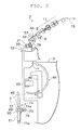
- FIG. 1 is a front view illustrating an overall structure of a fine spinning machine according to one embodiment of the present invention
- upstream and downstream respectively indicate upstream and downstream in a running direction of a yarn at the time of spinning (at the time of winding the yarn).
- the fine spinning machine (a spinning machine, a yarn winding machine) 1 illustrated in FIG. 1 includes a plurality of spinning units (winding units) 2 arranged side by side, a yarn joining vehicle 3, a blower box 4, and a motor box 5.
- each of the spinning units 2 includes as main components, a draft device 11, a spinning device (a yarn supplying device) 9, a yarn slack eliminating device (a yarn accumulating device) 12, and a winding device 7 arranged in this order from upstream towards downstream.
- the spinning unit 2 is adapted to spin a fiber bundle 8 fed from the draft device 11 by the spinning device 9 to produce a spun yarn (a yarn) 10, and to wind the spun yarn 10 by the winding device 7 to form a package 80.
- a sliver 15 as a material of the fiber bundle 8 is supplied to the draft device 11 from a sliver case (not illustrated) via a sliver guide.
- the draft device 11 includes a plurality of draft rollers each of which is rotationally driven, and a plurality of opposing rollers arranged to oppose the draft rollers.
- the draft device 11 is adapted to stretch (draft) the sliver 15 until a width thereof becomes a predetermined width to produce the fiber bundle 8 by sandwiching and transporting the sliver 15 between the draft rollers and the opposing rollers.
- the spinning device 9 is adapted to apply twists to the fiber bundle 8 fed from the draft device 11 to produce the spun yarn 10. Although a detailed structure of the spinning device 9 is not illustrated, the spinning device 9 of the present embodiment is a pneumatic-type adapted to apply twists to the fiber bundle 8 using whirling airflow.
- the yarn slack eliminating device 12 is arranged downstream of the spinning device 9.
- the yarn slack eliminating device 12 has a function to apply predetermined tension to the spun yarn 10 to draw the spun yarn 10 from the spinning device 9, a function to accumulate the spun yarn 10 fed from the spinning device 9, for example, when yarn joining operation is performed by the yarn joining vehicle 3 to prevent the spun yarn 10 from slackening, and a function to adjust tension such that variation in the tension at downstream does not propagate to the spinning device 9.
- the yarn slack eliminating device 12 includes a slack eliminating roller 21 and a yarn hooking member 22.
- the slack eliminating roller 21 is capable of accumulating the spun yarn 10 by winding a certain amount of the spun yarn 10 around an outer peripheral surface thereof.
- the slack eliminating roller 21 is rotationally driven by an electric motor 25 illustrated in FIG. 2 .
- the yarn hooking member 22 is arranged to be capable of hooking the spun yarn 10 thereon and winding the spun yarn 10 around the outer peripheral surface of the slack eliminating roller 21 by integrally rotating with the slack eliminating roller 21 while being engaged with the spun yarn 10.
- the yarn hooking member 22 and the slack eliminating roller 21 are connected by a resistance applying section (not illustrated) adapted to apply resistance in an appropriate manner such as a magnetic or an electric manner.
- the resistance applying section applies an appropriate amount of resistance torque that opposes rotation of the yarn hooking member 22 with respect to the slack eliminating roller 21. Accordingly, a state in which the yarn hooking member 22 is integrally rotated with the slack eliminating roller 21 and a state in which the yarn hooking member 22 is independently rotated are appropriately switched in accordance with tension on the spun yarn 10 hooked on the yarn hooking member 22. Consequently, variation in the tension of the spun yarn 10 can be absorbed.
- a yarn quality measuring device 52 is arranged at a position between the spinning device 9 and the yarn slack eliminating device 12.
- the spun yarn 10 produced by the spinning device 9 passes the yarn quality measuring device 52 before being wound by the yarn slack eliminating device 12.
- the yarn quality measuring device 52 is adapted to monitor a thickness of the running spun yarn 10 and to transmit a yarn defect detection signal to a unit controller (a control section), which is not illustrated, upon detection of a yarn defect in the spun yarn 10.
- the yarn quality measuring device 52 may detect a presence and/or an absence of a foreign substance in the spun yarn 10 as a presence and/or an absence of the yarn defect.
- the unit controller When receiving the yarn defect detection signal, the unit controller immediately cuts the spun yarn 10 by a cutter 57 and stops the draft device 11, the spinning device 9, the winding device 7, and the like. The spun yarn 10 may be cut by stopping spinning of the spinning device 9. The unit controller then transmits a control signal to the yarn joining vehicle 3 and controls the yarn joining vehicle 3 to run to the relevant spinning unit 2. Subsequently, the unit controller again drives the draft device 11, the spinning device 9, the winding device 7, and the like, controls the yarn joining vehicle 3 to perform yarn joining operation, and restarts winding of the package 80 in the relevant spinning unit 2 (the yarn joining operation performed by the yarn joining vehicle 3 will be described later in detail).
- the yarn slack eliminating device 12 accumulates the spun yarn 10 continuously fed from the spinning device 9 around the slack eliminating roller 21 to remove a slack of the spun yarn 10.
- the yarn joining vehicle 3 includes a splicer (a yarn joining device) 43, a suction pipe (a first catching and guiding member) 44, and a suction mouth (a second catching and guiding member) 46.
- a splicer a yarn joining device
- a suction pipe a first catching and guiding member
- a suction mouth a second catching and guiding member 46.
- the yarn joining vehicle 3 runs on a rail 41 to such a spinning unit 2 and stops.
- the suction pipe 44 swings in an upper direction with an axis as a center, and sucks and catches a yarn end fed from the spinning device 9.
- the suction pipe 44 then swings in a lower direction with the axis as the center and guides the caught yarn end to the splicer 43.
- the suction mouth 46 swings in the lower direction with an axis as a center, and sucks and catches a yarn end from the package 80.
- the suction mouth 46 then swings in the upper direction with the axis as the center and guides the caught yarn end to the splicer 43.
- the splicer 43 performs yarn joining of the guided yarn ends.
- the winding device 7 includes a cradle (a supporting section) 71, a bobbin holder (a holding section) 72, a winding drum 73, and a traverse device 74.
- the cradle 71 is formed of a pair of arm members that are long in a lengthwise direction.
- the cradle 71 is capable of supporting a bobbin 60 and the package 80.
- a pair (two pieces) of the bobbin holders 72 is attached to the cradle 71.
- the bobbin holders 72 respectively hold ends of the bobbin 60 and are capable of rotatably supporting the bobbin 60.
- the winding drum 73 is a drum-shaped component fixed to a drive shaft 79 provided to the fine spinning machine 1. Drive force of an appropriate drive source (an electric motor, for example) is transmitted to the drive shaft 79.
- the winding drum 73 can frictionally drive the bobbin 60 or the package 80 by being driven while being in contact with an outer peripheral surface of the bobbin 60 or the package 80 supported by the cradle 71 (the bobbin holders 72).
- the traverse device 74 includes a traverse guide 74a capable of guiding the spun yarn 10.
- a drive means not illustrated
- the winding device 7 rotates the package 80 in contact with the winding drum 73 and winds the spun yarn 10 while traversing.
- a base portion of the cradle 71 is arranged swingably about a support shaft 71a.
- An actuator (not illustrated) is coupled to the cradle 71. By driving the actuator, a state in which the bobbin 60 or the package 80 is in contact with the winding drum 73 and a state in which the bobbin 60 or the package 80 is located away from the winding drum 73 can be switched.
- the winding device 7 is provided with a brake mechanism, which is not illustrated, and is capable of braking rotation of the package 80 located away from the winding drum 73.
- the winding drum 73 of the present embodiment is a cylindrical component having an outer peripheral surface that can make contact with the bobbin 60 or the package 80.
- the winding drum 73 is formed such that an entire length (an axial length) 73L thereof is longer than a winding width 80W of the package 80.
- the fine spinning machine 1 of the present embodiment is for so-called 6-inch winding.
- a stroke (hereinafter may be referred to as a traverse stroke) of the traverse guide 74a of the traverse device 74 is set to form the package 80 having the winding width 80W of 152 millimeters.
- the entire length 73L of the winding drum 73 is longer than the winding width 80W (152 millimeters).
- the winding drum 73 includes a drum main body 75 and a high-frictional portion 76.
- the drum main body 75 is a cylindrical member forming a large portion of the winding drum 73.
- the entire length 73L of the winding drum 73 corresponds to an entire length of the drum main body 75.
- the drum main body 75 is fixed to the drive shaft 79. Thus, by driving the drive shaft 79 by an electric motor or the like, for example, the drum main body 75 can be rotationally driven.
- the high-frictional portion 76 is a ring-shaped member formed of elastically deformable rubber. In the present embodiment, a plurality of (two) high-frictional portions 76 are arranged around an outer periphery of the drum main body 75. A frictional surface 77, which is an outer peripheral surface of the high-frictional portion 76, forms a portion of an outer peripheral surface of the winding drum 73.
- the frictional surface 77 formed on each of the high-frictional portions 76 is adapted to slightly protrude in a radial direction from an outer peripheral surface of the drum main body 75.
- the frictional surfaces 77 formed on the high-frictional portions 76 make contact with the bobbin 60 or the package 80 stronger than an outer peripheral surface of a portion of the drum main body 75 where the high-frictional portion 76 is not arranged (there may be a case in which only the frictional surfaces 77 of the high-frictional portions 76 make contact with the bobbin 60 or the package 80 depending on hardness of the package 80, or the like).
- the high-frictional portions 76 of the winding drum 73 can further stably make contact with the package 80.
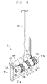
- the frictional surfaces 77 formed on the high-frictional portions 76 are arranged so as to avoid making contact with both ends of the package 80 in a winding width direction. As illustrated in FIG. 3 , the high-frictional portions 76 are respectively arranged on a right side and a left side of the winding drum 73 one by one. A left end of the frictional surface 77 formed on the high-frictional portion 76 on the left side is located at a position closer to a center in the winding width direction than a left end of the package 80. A right end of the frictional surface 77 formed on the high-frictional portion 76 on the right side is located at a position closer to the center in the winding width direction than a right end of the package 80.
- an axial distance 76L from the left end of the high-frictional portion 76 on the left side of the winding drum 73 in FIG. 3 to the right end of the high-frictional portion 76 on the right side of the winding drum 73 is less than 152 millimeters.
- the axial distance 76L between a point closest to a left end of the winding drum 73 and a point closest to a right end of the winding drum 73 is less than 152 millimeters.
- the "winding width" of the package 80 means a winding width at the time of traversing and winding the spun yarn 10 by the winding device 7. That is, in some cases, a middle portion of a yarn layer of the package 80 is deformed to protrude outward due to great winding tension of the spun yarn 10 after the package 80 has been fully wound and doffed, but the "winding width" in the present specification means a winding width not considering such a subsequent deformation.
- the high-frictional portions 76 are fixed by being fitted into ring-shaped groove portions 78 formed around the outer periphery of the drum main body 75.
- the groove portions 78 are formed in the same width as the high-frictional portions 76.
- the groove portions 78 are arranged to correspond to the number and attached positions of the high-frictional portions 76.
- the high-frictional portions 76 are formed into a cylinder shape having a certain thickness. Inner diameters of the high-frictional portions 76 are formed smaller than an outer diameter of a portion of the drum main body 75, which has become small due to the groove portion 78 being formed.
- the high-frictional portions 76 formed of rubber are attached to the groove portions 78 while being elastically deformed outward in a radial direction, the high-frictional portions 76 are strongly fixed to the groove portions 78 of the drum main body 75 by restoring force that acts inward in the radial direction. Consequently, without using a fixing means such as an adhesive or the like, the high-frictional portions 76 and the drum main body 75 can be integrally rotated without slipping from each other.
- the thicknesses of the high-frictional portions 76 are formed slightly larger than depths of the groove portions 78 of the winding drum 73. Accordingly, the frictional surfaces 77 formed on the high-frictional portions 76 attached to the groove portions 78 of the drum main body 75 can be slightly protruded from the outer peripheral surface of the drum main body 75.
- the high-frictional portions 76 are formed of rubber. Knurling processing is performed on the frictional surfaces 77 formed on the high-frictional portions 76, and a minute concave and a minute recess are formed to increase a friction coefficient. In such a manner, the package 80 can be driven with greatly secured frictional force generated between the high-frictional portions 76 and the package 80. Thus, when driving the package 80 by the high-frictional portions 76, even a heavy nearly fully-wound package 80 can be promptly shifted from a stop state to a high-speed rotation state.
- productivity of the package 80 can be advantageously improved.
- the fine spinning machine 1 of the present embodiment interrupts winding upon detection of a yarn defect by the yarn quality measuring device 52 and restarts the winding after the yarn defect has been removed and yarn joining operation has been performed, stop and restart of winding in the winding device 7 may be frequently repeated.
- prompt shift from a rotation stop state to a normal rotational speed is essential to improve productivity.
- the straight winding means that the spun yarn 10 is not traversed and is wound around a same portion. That is, when the spun yarn 10 is started being wound around an empty bobbin 60 or when interrupted winding is restarted, first, rotation of the bobbin 60 or the package 80 is started under a state in which the spun yarn 10 is not hooked on the traverse guide 74a, and the spun yarn 10 is wound without being traversed (for example, around a position close to the center in the winding width of the package 80).
- traverse of the spun yarn 10 is started.
- a reason for delaying start of the traverse of the spun yarn 10 is that since tension of the spun yarn 10 is unstable under a state where the rotational speed of the bobbin 60 or the package 80 is insufficient, the spun yarn 10 may not be engaged with the traverse guide 74a or winding cannot be performed due to the spun yarn 10 being entangled with the traverse guide 74a.
- the straight winding is formed while the rotational speed of the bobbin 60 or the package 80 has not reached the normal rotational speed, but the straight winding decreases quality of the package 80.
- the winding drum 73 of the present embodiment includes the high-frictional portions 76, the bobbin 60 or the package 80 can be promptly shifted from the rotation stop state to a normal rotational state. Consequently, the package 80 having less straight winding and high quality can be produced.
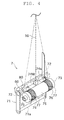
- the traverse guide 74a is driven and reciprocated within a predetermined traverse stroke 74W illustrated in FIG. 4 .
- the winding device 7 winds the spun yarn 10 around the outer peripheral surface of the rotating package 80 while traversing the spun yarn 10.
- the traverse stroke 74W of the traverse guide 74a includes and is larger than a width from an outermost end on one side to an outermost end on another side in an axial direction in which the high-frictional portions 76 (the frictional surfaces 77) of the winding drum 73 are arranged. If description is made with reference to a direction in FIG.
- an end on a left side of the traverse stroke 74W of the traverse guide 74a is located further to the left of the left end of the high-frictional portion 76 on the left side of the winding drum 73, and an end on a right side of the traverse stroke 74W is located further to the right of the right end of the high-frictional portion 76 on the right side.
- the traverse stroke 74W of the traverse guide 74a includes and is larger than an entire width (a length corresponding to the axial distance 76L in FIG. 3 ) of the frictional surfaces 77 formed on the plurality of high-frictional portions 76. Accordingly, the spun yarn 10 can be wound around the package 80 while being traversed so as to pass over contact portions of the high-frictional portions 76 of the winding drum 73 and the package 80.
- the spun yarn 10 is wound in a zig-zag manner while being turned at both ends of the winding width of the package 80 by being traversed by the traverse guide 74a.
- a yarn is turned while receiving strong friction or restriction between the frictional driving section and the package.
- a traverse width of the traverse guide 74a is formed to be larger than a width of a region where the high-frictional portions 76 of the winding drum 73 are arranged.
- the high-frictional portions 76 of the winding drum 73 are arranged in relation to the traverse stroke 74W of the traverse guide 74a such that the high-frictional portions 76 do not make contact with both ends of the package 80.
- the spun yarn 10 around the turning point can be prevented from making contact with the high-frictional portions 76 of the winding drum 73, even if irregular force is applied to the spun yarn 10, the force can be easily deflected by the spun yarn 10 being deformed or the like as required. Consequently, a yarn breakage of the spun yarn 10 around the ends of the traverse stroke 74W can be effectively prevented.
- Tendency of hardness of the package 80 in an axial direction thereof will be described.
- tension of the spun yarn 10 when the traverse guide 74a is located at an end of the traverse stroke 74W is greater than when the traverse guide 74a is located at a center thereof since a yarn path of the spun yarn 10 is longer.
- density of the spun yarn 10 is high since the spun yarn 10 is turned. Accordingly, the package 80 is harder at the both ends in the axial direction than the center.
- the high-frictional portions 76 are arranged to make contact with not both ends of the package 80, but positions slightly close to the center. Since the fine spinning machine 1 of the present embodiment is provided with the yarn slack eliminating device 12, variation in tension of the spun yarn 10 between a center and ends of the traverse stroke 74W can be favorably reduced by the yarn slack eliminating device 12. Consequently, difference in hardness that occurs between the center and both ends of the winding width of the package 80 can be reduced. Thus, even when the high-frictional portions 76 are made into contact with not both ends of the package 80, but the portions slightly close to the center and are driven, favorable drive force can be obtained.
- FIG. 5 illustration of the traverse guide 74a is omitted for convenience of description.
- the same reference numerals are denoted on the same members as or similar members with the above-described embodiment, and description may be omitted.
- the high-frictional portion 76 may be further provided to a substantially central position in the winding width (the traverse stroke 74W) of the package 80.
- the high-frictional portion 76 at the central position is arranged at a position that bisects the axial length of the winding drum 73.
- a yarn breakage of the spun yarn 10 around the ends of the traverse stroke 74W can be prevented.
- the high-frictional portions 76 are arranged so as to avoid a position around the central position (a position where straight winding is performed) in the winding width of the package 80. Accordingly, since straight winding is stably performed, quality of the package 80 can be improved.
- the winding drum 73 of the winding device 7 in the fine spinning machine 1 of the present embodiment rotates in contact with the package 80 to frictionally drive the package 80.
- the winding drum 73 includes the plurality of high-frictional portions 76.
- Each of the plurality of high-frictional portions 76 is provided with the frictional surface 77 that forms a portion of the outer peripheral surface of the winding drum 73.
- a surface shape and a material of the frictional surfaces 77 differ from the drum main body 75 such that the frictional surfaces 77 have a frictional force higher than other portion (the outer peripheral surface of the drum main body 75).
- Both of the high-frictional portions 76 are arranged such that the frictional surfaces 77 make contact with inner portions of the package 80 located inward with respect to ends of the package 80.
- a heavy package 80 can be promptly shifted from the stop state to the high-speed rotation state by being strongly driven with the high-frictional portions 76. Furthermore, since the frictional surfaces 77 formed on the high-frictional portions 76 are arranged to make contact with the inner portions of the package 80 located inward with respect to the ends of the package 80, even if irregular force is applied to the spun yarn 10 when the spun yarn 10 is wound around either end of the package 80, the force can be easily released. Consequently, a yarn breakage can be effectively prevented from occurring at both ends of the package 80.
- the axial distance 76L between the point closest to one end of the winding drum 73 and the point closest to another end of the winding drum 73 is less than 152 millimeters. 152 millimeters is one example of the winding width 80W of the package 80.
- the winding drum 73 of the present embodiment has the axial length of at least 152 millimeters.
- the spun yarn 10 when the spun yarn 10 is wound around either end of the 6-inch package 80, the spun yarn 10 is located on a surface other than the frictional surfaces 77 of the outer peripheral surface of the winding drum 73.
- a shape of the package 80 can be stabilized.
- the frictional surfaces 77 formed on the high-frictional portions 76 are arranged so as to avoid the position that bisects the axial length of the winding drum 73.
- the winding drum, along its axial length has a central portion (also referred to as center or middle of the winding drum), and the frictional surface formed on the high-frictional portion is arranged offset from the central portion of the winding drum in a direction along the axial length of the winding drum.
- the frictional surfaces 77 formed on the high-frictional portions 76 can be prevented from making contact with a straight winding portion that is frequently formed around the center of the package 80 in the axial direction thereof (the straight winding portion generally makes contact with the center of the winding drum 73 in its axial direction), and thus the outer peripheral surface of the package 80 can be prevented from being disarranged.
- the high-frictional portions 76 are formed of rubber.
- the package 80 can be strongly driven and rotated with a low-cost configuration.
- a concave and a recess are formed on the frictional surfaces 77 formed on the high-frictional portions 76.
- the package 80 can be strongly and frictionally driven.
- the winding device 7 of the fine spinning machine 1 of the present embodiment includes the winding drum 73 and the traverse guide 74a.
- the traverse guide 74a traverses the spun yarn 10 within a stroke including and larger than the entire width of the frictional surfaces 77 formed on the (plurality of) high-frictional portions 76.
- the winding device 7 of the present embodiment includes two bobbin holders 72 and the cradle 71.
- the bobbin holders 72 rotatably hold the ends of the bobbin 60 for a cheese package.
- the cradle 71 supports the bobbin holders 72.
- the cheese package means a package formed by a yarn being wound around a cylindrical bobbin (core tube).
- a yarn breakage can be prevented from occurring at both ends of a cheese package 80, and the package 80 with high quality can be produced.
- the fine spinning machine 1 of the present embodiment includes the winding device 7 and the yarn slack eliminating device 12.
- the yarn slack eliminating device 12 is arranged upstream of the winding device 7 in a yarn running direction.
- the yarn slack eliminating device 12 absorbs variation in tension of the spun yarn 10 between the yarn slack eliminating device 12 and the winding device 7.
- the high-frictional portions 76 of the winding drum 73 are arranged so as to avoid the position where the spun yarn 10 is wound without being traversed by the traverse guide 74a immediately after start of rotation of the winding drum 73.
- the high-frictional portions 76 can be prevented from making contact with a straight winding portion and disarranging a yarn layer, improvement in quality of the package 80 can be realized.
- the fine spinning machine 1 of the present embodiment includes the spinning device 9, the splicer 43, the suction pipe 44, and the suction mouth 46.
- the suction pipe 44 catches the spun yarn 10 from the spinning device 9 and guides the caught spun yarn 10 to the splicer 43.
- the suction mouth 46 catches the spun yarn 10 from the package 80 and guides the caught spun yarn 10 to the splicer 43.
- the spun yarn 10 after the spun yarn 10 has been cut upon detection of a yarn defect or after a yarn breakage has occurred, the spun yarn 10 can be caught and yarn joining can be performed.
- rotation of the package 80 needs to be stopped in the winding device 7 to perform yarn joining operation by the splicer 43, and the rotation of the package 80 needs to be restarted after the yarn joining operation.
- a second alternative embodiment will be described with reference to FIG. 6 .
- a winding drum 73y of the second alternative embodiment merely one high-frictional portion 76x is arranged at one end of the package 80.
- the high-frictional portion 76x is arranged between one end and the central portion of the winding width of the package 80.
- a width of the high-frictional portion 76x is formed larger than the high-frictional portion 76 of the winding drum 73 illustrated in FIG. 4 to strongly drive the package 80. Accordingly, the winding drum 73y that can prevent a yarn breakage from occurring at both ends of the package 80 with a small number of components can be provided.
- two high-frictional portions 76 are preferably arranged in a symmetric manner as illustrated in FIG. 4 .
- the winding drum 73y of the present alternative embodiment is adapted to rotate in contact with the cheese package 80 to frictionally drive the package 80.
- the winding drum 73y includes the high-frictional portion 76x.
- the high-frictional portion 76x is provided with the frictional surface 77 that forms a portion of an outer peripheral surface of the winding drum 73y.
- a surface shape and a material of the frictional surface 77 differ from other portion of the outer peripheral surface such that a frictional force of the frictional surface 77 is higher than the other portion.
- the high-frictional portion 76x is arranged such that the frictional surface 77 makes contact with an inner portion of the package 80 located inward with respect to an end of the package 80.
- the cheese package 80 can be promptly driven by the high-frictional portion 76x arranged so as to avoid both ends of the package 80, and a yarn breakage can be prevented from occurring at both ends of the package 80.
- a winding drum 73z of the third alternative embodiment is formed of a plurality of components divided in an axial direction thereof. Specifically, the winding drum 73z includes two high-frictional portions 76y, a first drum body 81, and two second drum bodies 82.
- the high-frictional portions 76y are formed into a short cylindrical shape with a material such as resin and the like, and knurling processing is performed on the frictional surfaces 77 that are outer peripheral surfaces of the high-frictional portions 76y. Both ends of the high-frictional portions 76y in the axial direction are formed into a saw-teeth shape.
- the first drum body 81 is formed into a cylindrical shape with a material such as resin and the like, and is arranged to be sandwiched between the high-frictional portions 76y. Both ends of the first drum body 81 in the axial direction are formed into a saw-teeth shape to correspond to the saw-teeth-shaped portions of the high-frictional portions 76y.
- the second drum bodies 82 are formed into a cylindrical shape with the same material as the first drum body 81 and are respectively arranged at positions corresponding to ends of the winding drum 73z. Ends on inner sides of the second drum bodies 82 in the axial direction are formed into a saw-teeth shape to correspond to the saw-teeth-shaped portions of the high-frictional portions 76y.
- the second drum body 82, the high-frictional portion 76y, the first drum body 81, the high-frictional portion 76y, and the second drum body 82 are arranged in this order from one end in the axial direction.
- every member is coupled in a relatively unrotatable manner. In such a manner, the winding drum 73z is formed.
- the winding drum 73z of the present alternative embodiment is advantageous in terms of a feature in which the spun yarn 10 is unlikely to enter into grooves formed in border portions since the border portions between the high-frictional portions 76y and other portions are a zigzag shape.
- a change in the winding width of the package 80 can be easily handled by preparing a plurality of first drum bodies 81 having different lengths and by replacing them as necessary.
- the material of the high-frictional portions 76, 76x, 76y is not limited to rubber and resin, and another material such as metal or the like may be used.
- the material of the high-frictional portions 76, 76x, 76y may be same as a material of another portion of a winding drum (for example, the drum main body 75, the first drum body 81, or the second drum body 82).
- a frictional force of the frictional surface 77 may be increased with respect to other portion, for example, by increasing the frictional coefficient of the frictional surface 77 with unevenness treatment such as knurling processing or the like that forms a concave and a recess on the frictional surface 77.
- the knurling processing does not necessarily need to be performed on the frictional surface 77 in particular.
- the same knurling processing may be performed on both of the frictional surface 77 and other portion (for example, each outer peripheral surface of the drum main body 75, the first drum body 81, or the second drum body 82).
- a frictional force of the high-frictional portion 76 can be increased with respect to the other portion by respectively forming the drum main body 75 and the high-frictional portion 76 with resin and rubber.
- a method for fixing the high-frictional portions 76, 76x, 76y is not limited to using the groove portion 78 or a sew-teeth-shaped portion, and an adhesive and/or a screw, for example, may be used.
- the present invention is not limited to so-called 6-inch winding, and may be applied to a winding drum for 3-inch winding or 4-inch winding, or a winding drum to form a package having a large winding width exceeding 6-inch winding.
- application of the present invention is not precluded even to a winding drum and a winding device to form a package wound with a traverse width other than 152 millimeters.
- a high-frictional portion may be arranged such that a frictional surface formed on the high-frictional portion makes contact with an inner portion of a package located inward with respect to an end of the package or an entire width of the frictional surface is within a stroke of a traverse guide.
- the traverse device 74 described in the above-described embodiment reciprocates the traverse guide 74a at a position where a certain degree of gap is formed with respect to both of the outer peripheral surface of the winding drum 73 and the outer peripheral surface of the package 80 to avoid colliding with a component and the like in proximity.
- a distance between a position where the spun yarn 10 is engaged with the traverse guide 74a and a position where the spun yarn 10 makes contact with the outer peripheral surface of the winding drum 73 or the package 80 cannot be zero.
- the distance is referred to as a free length. When the free length is long, a space where traverse by the traverse guide 74a is absorbed by deformation of the spun yarn 10 is increased.
- a winding width of the package 80 formed when the free length is long is smaller than a winding width of the package 80 formed when the free length is short. Due to such a condition of the free length, even when the traverse stroke is set to 152 millimeters or more, the winding width of the package 80 may be narrower than 152 millimeters.
- the high-frictional portion 76 (76x, 76y) may be arranged such that the frictional surface 77 makes contact with a further inner portion of the package 80 with respect to the winding width narrower than 152 millimeters.
- the winding width of the package 80 is not necessarily constant from start of winding of the spun yarn 10 around the bobbin 60 until the package 80 becomes nearly fully-wound.
- the package 80 under an initial state in which the spun yarn 10 is started being wound around the bobbin 60, the package 80 is hard due to a thin yarn layer, but when the winding proceeds and the yarn layer becomes thick, the package 80 may become soft. Then, a point where the winding drum 73 and the package 80 substantially make contact with each other is gradually moved upstream or downstream as winding proceeds, and the free length may be varied accompanying the movement and influence the winding width. In this manner, the winding width of the package 80 may be varied depending on a situation from start of winding until a fully-wound package is obtained.
- the high-frictional portion 76 (76x, 76y) is preferably arranged to make contact with an inner portion of the package 80 located inward with respect to a width of the package 80 of when the winding width of the package 80 is narrowest.
- the spun yarn 10 is drawn from the spinning device 9 by the yarn slack eliminating device 12.
- the spun yarn 10 may be drawn by a delivery roller and a nip roller arranged downstream of the spinning device 9, and the drawn spun yarn 10 may be accumulated by the yarn slack eliminating device 12 located downstream.
- a winding drum and a winding device of the present invention are not limited to a spinning machine such as a fine spinning machine or the like, and may be widely applied, for example, to a yarn winding machine such as an automatic winder provided with a yarn supplying device in which a yarn supplying bobbin with a yarn wound therearound can be set.
Landscapes
- Winding Filamentary Materials (AREA)
Applications Claiming Priority (1)
| Application Number | Priority Date | Filing Date | Title |
|---|---|---|---|
| JP2014092042A JP2015209309A (ja) | 2014-04-25 | 2014-04-25 | 巻取ドラム、巻取装置及び糸巻取機 |
Publications (2)
| Publication Number | Publication Date |
|---|---|
| EP2937303A1 true EP2937303A1 (fr) | 2015-10-28 |
| EP2937303B1 EP2937303B1 (fr) | 2018-03-28 |
Family
ID=52814003
Family Applications (1)
| Application Number | Title | Priority Date | Filing Date |
|---|---|---|---|
| EP15162780.9A Not-in-force EP2937303B1 (fr) | 2014-04-25 | 2015-04-08 | Tambour d'enroulement, dispositif d'enroulement et machine de bobinage de fil |
Country Status (3)
| Country | Link |
|---|---|
| EP (1) | EP2937303B1 (fr) |
| JP (1) | JP2015209309A (fr) |
| CN (1) | CN105035856B (fr) |
Cited By (1)
| Publication number | Priority date | Publication date | Assignee | Title |
|---|---|---|---|---|
| CN112051171A (zh) * | 2020-08-24 | 2020-12-08 | 阜阳恒泰纺织有限公司 | 一种亚麻与再生纤维素纤维混纺色纺纱的检测装置 |
Families Citing this family (2)
| Publication number | Priority date | Publication date | Assignee | Title |
|---|---|---|---|---|
| CN108861775A (zh) * | 2018-07-05 | 2018-11-23 | 河南金宏印业有限公司 | 传递辊可调节的印刷机 |
| CN109132713A (zh) * | 2018-09-18 | 2019-01-04 | 郑州赫恩电子信息技术有限公司 | 一种通讯设备的线缆收纳装置 |
Citations (12)
| Publication number | Priority date | Publication date | Assignee | Title |
|---|---|---|---|---|
| US3343753A (en) * | 1965-03-05 | 1967-09-26 | Monsanto Co | Yarn winding process and product |
| DE2449242A1 (de) * | 1974-10-16 | 1976-04-22 | Barmag Barmer Maschf | Treibwalze fuer spulmaschinen |
| JPS5199141A (ja) * | 1975-02-26 | 1976-09-01 | Teijin Ltd | Makitorisochi |
| DE2720935A1 (de) * | 1977-05-10 | 1978-11-16 | Schlafhorst & Co W | Wickelwalze |
| JPH0188680U (fr) | 1987-12-01 | 1989-06-12 | ||
| JPH0190759U (fr) * | 1987-12-08 | 1989-06-14 | ||
| EP0340440A1 (fr) * | 1988-05-05 | 1989-11-08 | W. SCHLAFHORST AG & CO. | Dispositif de bobinage de fil |
| JPH0353963U (fr) | 1989-10-02 | 1991-05-24 | ||
| JPH0769533A (ja) | 1993-09-03 | 1995-03-14 | Murata Mach Ltd | 巻取装置 |
| JPH0859076A (ja) * | 1994-08-12 | 1996-03-05 | Toray Ind Inc | 糸条巻取用タッチローラ |
| EP1457446A2 (fr) * | 2003-03-13 | 2004-09-15 | Murata Kikai Kabushiki Kaisha | Dispositif de réglage de tension et d'élimination des relâchements de fil pour un dispositif de bobinage |
| EP2620403A2 (fr) * | 2012-01-30 | 2013-07-31 | Murata Machinery, Ltd. | Bobinoir de fil et procédé de bobinage de fil |
Family Cites Families (4)
| Publication number | Priority date | Publication date | Assignee | Title |
|---|---|---|---|---|
| DE4339217A1 (de) * | 1993-11-18 | 1995-05-24 | Schlafhorst & Co W | Verfahren zum Steuern einer Spulstelle einer Spulmaschine bei Auflaufspulenwechsel und Spulstelle zur Durchführung des Verfahrens |
| EP1256540A3 (fr) * | 2001-05-11 | 2003-07-16 | Murata Kikai Kabushiki Kaisha | Machine et procédé pour bobiner du fil textile |
| EP1626024A1 (fr) * | 2004-08-10 | 2006-02-15 | Maschinenfabrik Rieter Ag | Dispositif de va-et-vient chez un métier à filer |
| CN103538965A (zh) * | 2013-09-26 | 2014-01-29 | 吴江伊莱纺织科技有限公司 | 一种适用锥形筒纱管的摩擦辊 |
-
2014
- 2014-04-25 JP JP2014092042A patent/JP2015209309A/ja active Pending
-
2015
- 2015-04-08 EP EP15162780.9A patent/EP2937303B1/fr not_active Not-in-force
- 2015-04-09 CN CN201510166141.5A patent/CN105035856B/zh active Active
Patent Citations (12)
| Publication number | Priority date | Publication date | Assignee | Title |
|---|---|---|---|---|
| US3343753A (en) * | 1965-03-05 | 1967-09-26 | Monsanto Co | Yarn winding process and product |
| DE2449242A1 (de) * | 1974-10-16 | 1976-04-22 | Barmag Barmer Maschf | Treibwalze fuer spulmaschinen |
| JPS5199141A (ja) * | 1975-02-26 | 1976-09-01 | Teijin Ltd | Makitorisochi |
| DE2720935A1 (de) * | 1977-05-10 | 1978-11-16 | Schlafhorst & Co W | Wickelwalze |
| JPH0188680U (fr) | 1987-12-01 | 1989-06-12 | ||
| JPH0190759U (fr) * | 1987-12-08 | 1989-06-14 | ||
| EP0340440A1 (fr) * | 1988-05-05 | 1989-11-08 | W. SCHLAFHORST AG & CO. | Dispositif de bobinage de fil |
| JPH0353963U (fr) | 1989-10-02 | 1991-05-24 | ||
| JPH0769533A (ja) | 1993-09-03 | 1995-03-14 | Murata Mach Ltd | 巻取装置 |
| JPH0859076A (ja) * | 1994-08-12 | 1996-03-05 | Toray Ind Inc | 糸条巻取用タッチローラ |
| EP1457446A2 (fr) * | 2003-03-13 | 2004-09-15 | Murata Kikai Kabushiki Kaisha | Dispositif de réglage de tension et d'élimination des relâchements de fil pour un dispositif de bobinage |
| EP2620403A2 (fr) * | 2012-01-30 | 2013-07-31 | Murata Machinery, Ltd. | Bobinoir de fil et procédé de bobinage de fil |
Cited By (1)
| Publication number | Priority date | Publication date | Assignee | Title |
|---|---|---|---|---|
| CN112051171A (zh) * | 2020-08-24 | 2020-12-08 | 阜阳恒泰纺织有限公司 | 一种亚麻与再生纤维素纤维混纺色纺纱的检测装置 |
Also Published As
| Publication number | Publication date |
|---|---|
| CN105035856B (zh) | 2019-07-26 |
| EP2937303B1 (fr) | 2018-03-28 |
| CN105035856A (zh) | 2015-11-11 |
| JP2015209309A (ja) | 2015-11-24 |
Similar Documents
| Publication | Publication Date | Title |
|---|---|---|
| EP2075359B1 (fr) | Dispositif d'élimination du relâchement des fils et machine de filature | |
| EP2284300B1 (fr) | Fileuse et procédé de retrait de fil pour retirer le fil restant sur le rouleau d'accumulation de fils | |
| EP2213773B2 (fr) | Dispositif de capture d'extrémité de fil et fileuse l'incluant | |
| EP2407406B1 (fr) | Dispositif de liaison de peluches, unité d'application de tension et enrouleur automatique | |
| EP1916213B1 (fr) | Fileuse dotée d'un dispositif d'élimination du relâchement des fils | |
| EP2366651B1 (fr) | Dispositif de renvideur de fil | |
| EP2189557B1 (fr) | Dispositif d'élimination du relâchement des fils et machine textile incluant un tel dispositif | |
| EP2966200B1 (fr) | Métier à filer et procédé de filage | |
| JP2016016957A (ja) | 糸巻取機及び糸巻取方法 | |
| EP2573231B1 (fr) | Fileuse | |
| EP1717182B1 (fr) | Dispositif d'élimination des relâchements de fil dans une machine textile | |
| EP2937303B1 (fr) | Tambour d'enroulement, dispositif d'enroulement et machine de bobinage de fil | |
| JP5804306B2 (ja) | 糸貯留装置及び糸巻取機 | |
| JP2009046778A (ja) | 巻取テンション制御装置 | |
| JP2010180023A (ja) | 糸弛み取り装置及びこれを備える繊維機械 | |
| JP2014218314A (ja) | 糸巻取機 | |
| JP2013154991A (ja) | 糸巻取機及び糸巻取方法 | |
| EP2910507B1 (fr) | Dispositif d'accumulation de fil, unité de bobinage de fil le comprenant et machine de bobinage de fil comprenant cette unité | |
| EP2853510B1 (fr) | Véhicule de service d'une machine textile | |
| JP2009126647A (ja) | 巻取り装置及び巻取り方法 | |
| JP2010184758A (ja) | 糸貯留装置、これを備える繊維機械及び紡績機 | |
| JP2004277946A (ja) | 紡績機の糸弛み取り装置 | |
| JP2004277947A (ja) | 糸継ぎ装置を備えた紡績機 | |
| JP2004277943A (ja) | 紡績機 | |
| JP2015067440A (ja) | 繊維機械 |
Legal Events
| Date | Code | Title | Description |
|---|---|---|---|
| PUAI | Public reference made under article 153(3) epc to a published international application that has entered the european phase |
Free format text: ORIGINAL CODE: 0009012 |
|
| AK | Designated contracting states |
Kind code of ref document: A1 Designated state(s): AL AT BE BG CH CY CZ DE DK EE ES FI FR GB GR HR HU IE IS IT LI LT LU LV MC MK MT NL NO PL PT RO RS SE SI SK SM TR |
|
| AX | Request for extension of the european patent |
Extension state: BA ME |
|
| 17P | Request for examination filed |
Effective date: 20160205 |
|
| RBV | Designated contracting states (corrected) |
Designated state(s): AL AT BE BG CH CY CZ DE DK EE ES FI FR GB GR HR HU IE IS IT LI LT LU LV MC MK MT NL NO PL PT RO RS SE SI SK SM TR |
|
| 17Q | First examination report despatched |
Effective date: 20170313 |
|
| GRAP | Despatch of communication of intention to grant a patent |
Free format text: ORIGINAL CODE: EPIDOSNIGR1 |
|
| INTG | Intention to grant announced |
Effective date: 20171011 |
|
| GRAS | Grant fee paid |
Free format text: ORIGINAL CODE: EPIDOSNIGR3 |
|
| GRAA | (expected) grant |
Free format text: ORIGINAL CODE: 0009210 |
|
| AK | Designated contracting states |
Kind code of ref document: B1 Designated state(s): AL AT BE BG CH CY CZ DE DK EE ES FI FR GB GR HR HU IE IS IT LI LT LU LV MC MK MT NL NO PL PT RO RS SE SI SK SM TR |
|
| REG | Reference to a national code |
Ref country code: GB Ref legal event code: FG4D |
|
| REG | Reference to a national code |
Ref country code: CH Ref legal event code: EP |
|
| REG | Reference to a national code |
Ref country code: AT Ref legal event code: REF Ref document number: 983220 Country of ref document: AT Kind code of ref document: T Effective date: 20180415 |
|
| REG | Reference to a national code |
Ref country code: IE Ref legal event code: FG4D |
|
| REG | Reference to a national code |
Ref country code: DE Ref legal event code: R096 Ref document number: 602015009225 Country of ref document: DE |
|
| REG | Reference to a national code |
Ref country code: CH Ref legal event code: NV Representative=s name: BOVARD AG PATENT- UND MARKENANWAELTE, CH |
|
| PG25 | Lapsed in a contracting state [announced via postgrant information from national office to epo] |
Ref country code: FI Free format text: LAPSE BECAUSE OF FAILURE TO SUBMIT A TRANSLATION OF THE DESCRIPTION OR TO PAY THE FEE WITHIN THE PRESCRIBED TIME-LIMIT Effective date: 20180328 Ref country code: NO Free format text: LAPSE BECAUSE OF FAILURE TO SUBMIT A TRANSLATION OF THE DESCRIPTION OR TO PAY THE FEE WITHIN THE PRESCRIBED TIME-LIMIT Effective date: 20180628 Ref country code: HR Free format text: LAPSE BECAUSE OF FAILURE TO SUBMIT A TRANSLATION OF THE DESCRIPTION OR TO PAY THE FEE WITHIN THE PRESCRIBED TIME-LIMIT Effective date: 20180328 Ref country code: LT Free format text: LAPSE BECAUSE OF FAILURE TO SUBMIT A TRANSLATION OF THE DESCRIPTION OR TO PAY THE FEE WITHIN THE PRESCRIBED TIME-LIMIT Effective date: 20180328 |
|
| REG | Reference to a national code |
Ref country code: NL Ref legal event code: MP Effective date: 20180328 |
|
| REG | Reference to a national code |
Ref country code: LT Ref legal event code: MG4D |
|
| PG25 | Lapsed in a contracting state [announced via postgrant information from national office to epo] |
Ref country code: BG Free format text: LAPSE BECAUSE OF FAILURE TO SUBMIT A TRANSLATION OF THE DESCRIPTION OR TO PAY THE FEE WITHIN THE PRESCRIBED TIME-LIMIT Effective date: 20180628 Ref country code: GR Free format text: LAPSE BECAUSE OF FAILURE TO SUBMIT A TRANSLATION OF THE DESCRIPTION OR TO PAY THE FEE WITHIN THE PRESCRIBED TIME-LIMIT Effective date: 20180629 Ref country code: SE Free format text: LAPSE BECAUSE OF FAILURE TO SUBMIT A TRANSLATION OF THE DESCRIPTION OR TO PAY THE FEE WITHIN THE PRESCRIBED TIME-LIMIT Effective date: 20180328 Ref country code: LV Free format text: LAPSE BECAUSE OF FAILURE TO SUBMIT A TRANSLATION OF THE DESCRIPTION OR TO PAY THE FEE WITHIN THE PRESCRIBED TIME-LIMIT Effective date: 20180328 Ref country code: RS Free format text: LAPSE BECAUSE OF FAILURE TO SUBMIT A TRANSLATION OF THE DESCRIPTION OR TO PAY THE FEE WITHIN THE PRESCRIBED TIME-LIMIT Effective date: 20180328 |
|
| PG25 | Lapsed in a contracting state [announced via postgrant information from national office to epo] |
Ref country code: PL Free format text: LAPSE BECAUSE OF FAILURE TO SUBMIT A TRANSLATION OF THE DESCRIPTION OR TO PAY THE FEE WITHIN THE PRESCRIBED TIME-LIMIT Effective date: 20180328 Ref country code: EE Free format text: LAPSE BECAUSE OF FAILURE TO SUBMIT A TRANSLATION OF THE DESCRIPTION OR TO PAY THE FEE WITHIN THE PRESCRIBED TIME-LIMIT Effective date: 20180328 Ref country code: IT Free format text: LAPSE BECAUSE OF FAILURE TO SUBMIT A TRANSLATION OF THE DESCRIPTION OR TO PAY THE FEE WITHIN THE PRESCRIBED TIME-LIMIT Effective date: 20180328 Ref country code: AL Free format text: LAPSE BECAUSE OF FAILURE TO SUBMIT A TRANSLATION OF THE DESCRIPTION OR TO PAY THE FEE WITHIN THE PRESCRIBED TIME-LIMIT Effective date: 20180328 Ref country code: RO Free format text: LAPSE BECAUSE OF FAILURE TO SUBMIT A TRANSLATION OF THE DESCRIPTION OR TO PAY THE FEE WITHIN THE PRESCRIBED TIME-LIMIT Effective date: 20180328 Ref country code: ES Free format text: LAPSE BECAUSE OF FAILURE TO SUBMIT A TRANSLATION OF THE DESCRIPTION OR TO PAY THE FEE WITHIN THE PRESCRIBED TIME-LIMIT Effective date: 20180328 Ref country code: NL Free format text: LAPSE BECAUSE OF FAILURE TO SUBMIT A TRANSLATION OF THE DESCRIPTION OR TO PAY THE FEE WITHIN THE PRESCRIBED TIME-LIMIT Effective date: 20180328 |
|
| PG25 | Lapsed in a contracting state [announced via postgrant information from national office to epo] |
Ref country code: SM Free format text: LAPSE BECAUSE OF FAILURE TO SUBMIT A TRANSLATION OF THE DESCRIPTION OR TO PAY THE FEE WITHIN THE PRESCRIBED TIME-LIMIT Effective date: 20180328 Ref country code: SK Free format text: LAPSE BECAUSE OF FAILURE TO SUBMIT A TRANSLATION OF THE DESCRIPTION OR TO PAY THE FEE WITHIN THE PRESCRIBED TIME-LIMIT Effective date: 20180328 |
|
| REG | Reference to a national code |
Ref country code: AT Ref legal event code: MK05 Ref document number: 983220 Country of ref document: AT Kind code of ref document: T Effective date: 20180328 |
|
| REG | Reference to a national code |
Ref country code: BE Ref legal event code: MM Effective date: 20180430 |
|
| PG25 | Lapsed in a contracting state [announced via postgrant information from national office to epo] |
Ref country code: PT Free format text: LAPSE BECAUSE OF FAILURE TO SUBMIT A TRANSLATION OF THE DESCRIPTION OR TO PAY THE FEE WITHIN THE PRESCRIBED TIME-LIMIT Effective date: 20180730 |
|
| REG | Reference to a national code |
Ref country code: DE Ref legal event code: R097 Ref document number: 602015009225 Country of ref document: DE |
|
| REG | Reference to a national code |
Ref country code: IE Ref legal event code: MM4A |
|
| PG25 | Lapsed in a contracting state [announced via postgrant information from national office to epo] |
Ref country code: AT Free format text: LAPSE BECAUSE OF FAILURE TO SUBMIT A TRANSLATION OF THE DESCRIPTION OR TO PAY THE FEE WITHIN THE PRESCRIBED TIME-LIMIT Effective date: 20180328 Ref country code: DK Free format text: LAPSE BECAUSE OF FAILURE TO SUBMIT A TRANSLATION OF THE DESCRIPTION OR TO PAY THE FEE WITHIN THE PRESCRIBED TIME-LIMIT Effective date: 20180328 Ref country code: LU Free format text: LAPSE BECAUSE OF NON-PAYMENT OF DUE FEES Effective date: 20180408 Ref country code: MC Free format text: LAPSE BECAUSE OF FAILURE TO SUBMIT A TRANSLATION OF THE DESCRIPTION OR TO PAY THE FEE WITHIN THE PRESCRIBED TIME-LIMIT Effective date: 20180328 |
|
| PLBE | No opposition filed within time limit |
Free format text: ORIGINAL CODE: 0009261 |
|
| STAA | Information on the status of an ep patent application or granted ep patent |
Free format text: STATUS: NO OPPOSITION FILED WITHIN TIME LIMIT |
|
| PG25 | Lapsed in a contracting state [announced via postgrant information from national office to epo] |
Ref country code: BE Free format text: LAPSE BECAUSE OF NON-PAYMENT OF DUE FEES Effective date: 20180430 |
|
| 26N | No opposition filed |
Effective date: 20190103 |
|
| PG25 | Lapsed in a contracting state [announced via postgrant information from national office to epo] |
Ref country code: IE Free format text: LAPSE BECAUSE OF NON-PAYMENT OF DUE FEES Effective date: 20180408 Ref country code: FR Free format text: LAPSE BECAUSE OF NON-PAYMENT OF DUE FEES Effective date: 20180528 |
|
| PG25 | Lapsed in a contracting state [announced via postgrant information from national office to epo] |
Ref country code: SI Free format text: LAPSE BECAUSE OF FAILURE TO SUBMIT A TRANSLATION OF THE DESCRIPTION OR TO PAY THE FEE WITHIN THE PRESCRIBED TIME-LIMIT Effective date: 20180328 |
|
| GBPC | Gb: european patent ceased through non-payment of renewal fee |
Effective date: 20190408 |
|
| PG25 | Lapsed in a contracting state [announced via postgrant information from national office to epo] |
Ref country code: MT Free format text: LAPSE BECAUSE OF NON-PAYMENT OF DUE FEES Effective date: 20180408 Ref country code: GB Free format text: LAPSE BECAUSE OF NON-PAYMENT OF DUE FEES Effective date: 20190408 |
|
| PG25 | Lapsed in a contracting state [announced via postgrant information from national office to epo] |
Ref country code: TR Free format text: LAPSE BECAUSE OF FAILURE TO SUBMIT A TRANSLATION OF THE DESCRIPTION OR TO PAY THE FEE WITHIN THE PRESCRIBED TIME-LIMIT Effective date: 20180328 |
|
| PG25 | Lapsed in a contracting state [announced via postgrant information from national office to epo] |
Ref country code: CY Free format text: LAPSE BECAUSE OF FAILURE TO SUBMIT A TRANSLATION OF THE DESCRIPTION OR TO PAY THE FEE WITHIN THE PRESCRIBED TIME-LIMIT Effective date: 20180328 Ref country code: MK Free format text: LAPSE BECAUSE OF NON-PAYMENT OF DUE FEES Effective date: 20180328 Ref country code: HU Free format text: LAPSE BECAUSE OF FAILURE TO SUBMIT A TRANSLATION OF THE DESCRIPTION OR TO PAY THE FEE WITHIN THE PRESCRIBED TIME-LIMIT; INVALID AB INITIO Effective date: 20150408 |
|
| PG25 | Lapsed in a contracting state [announced via postgrant information from national office to epo] |
Ref country code: IS Free format text: LAPSE BECAUSE OF FAILURE TO SUBMIT A TRANSLATION OF THE DESCRIPTION OR TO PAY THE FEE WITHIN THE PRESCRIBED TIME-LIMIT Effective date: 20180728 |
|
| PGFP | Annual fee paid to national office [announced via postgrant information from national office to epo] |
Ref country code: CH Payment date: 20200420 Year of fee payment: 6 Ref country code: DE Payment date: 20200420 Year of fee payment: 6 Ref country code: CZ Payment date: 20200407 Year of fee payment: 6 |
|
| REG | Reference to a national code |
Ref country code: DE Ref legal event code: R119 Ref document number: 602015009225 Country of ref document: DE |
|
| PG25 | Lapsed in a contracting state [announced via postgrant information from national office to epo] |
Ref country code: DE Free format text: LAPSE BECAUSE OF NON-PAYMENT OF DUE FEES Effective date: 20211103 Ref country code: CZ Free format text: LAPSE BECAUSE OF NON-PAYMENT OF DUE FEES Effective date: 20210408 Ref country code: LI Free format text: LAPSE BECAUSE OF NON-PAYMENT OF DUE FEES Effective date: 20210430 Ref country code: CH Free format text: LAPSE BECAUSE OF NON-PAYMENT OF DUE FEES Effective date: 20210430 |