EP2937528B1 - Kombikraftwerk mit verbessertem Wirkungsgrad - Google Patents
Kombikraftwerk mit verbessertem Wirkungsgrad Download PDFInfo
- Publication number
- EP2937528B1 EP2937528B1 EP14190310.4A EP14190310A EP2937528B1 EP 2937528 B1 EP2937528 B1 EP 2937528B1 EP 14190310 A EP14190310 A EP 14190310A EP 2937528 B1 EP2937528 B1 EP 2937528B1
- Authority
- EP
- European Patent Office
- Prior art keywords
- gas turbine
- flash
- power plant
- combined cycle
- cycle power
- Prior art date
- Legal status (The legal status is an assumption and is not a legal conclusion. Google has not performed a legal analysis and makes no representation as to the accuracy of the status listed.)
- Active
Links
Images




Classifications
-
- F—MECHANICAL ENGINEERING; LIGHTING; HEATING; WEAPONS; BLASTING
- F01—MACHINES OR ENGINES IN GENERAL; ENGINE PLANTS IN GENERAL; STEAM ENGINES
- F01K—STEAM ENGINE PLANTS; STEAM ACCUMULATORS; ENGINE PLANTS NOT OTHERWISE PROVIDED FOR; ENGINES USING SPECIAL WORKING FLUIDS OR CYCLES
- F01K17/00—Using steam or condensate extracted or exhausted from steam engine plant
- F01K17/02—Using steam or condensate extracted or exhausted from steam engine plant for heating purposes, e.g. industrial, domestic
- F01K17/025—Using steam or condensate extracted or exhausted from steam engine plant for heating purposes, e.g. industrial, domestic in combination with at least one gas turbine, e.g. a combustion gas turbine
-
- F—MECHANICAL ENGINEERING; LIGHTING; HEATING; WEAPONS; BLASTING
- F01—MACHINES OR ENGINES IN GENERAL; ENGINE PLANTS IN GENERAL; STEAM ENGINES
- F01K—STEAM ENGINE PLANTS; STEAM ACCUMULATORS; ENGINE PLANTS NOT OTHERWISE PROVIDED FOR; ENGINES USING SPECIAL WORKING FLUIDS OR CYCLES
- F01K17/00—Using steam or condensate extracted or exhausted from steam engine plant
-
- F—MECHANICAL ENGINEERING; LIGHTING; HEATING; WEAPONS; BLASTING
- F01—MACHINES OR ENGINES IN GENERAL; ENGINE PLANTS IN GENERAL; STEAM ENGINES
- F01K—STEAM ENGINE PLANTS; STEAM ACCUMULATORS; ENGINE PLANTS NOT OTHERWISE PROVIDED FOR; ENGINES USING SPECIAL WORKING FLUIDS OR CYCLES
- F01K23/00—Plants characterised by more than one engine delivering power external to the plant, the engines being driven by different fluids
- F01K23/02—Plants characterised by more than one engine delivering power external to the plant, the engines being driven by different fluids the engine cycles being thermally coupled
- F01K23/06—Plants characterised by more than one engine delivering power external to the plant, the engines being driven by different fluids the engine cycles being thermally coupled combustion heat from one cycle heating the fluid in another cycle
- F01K23/10—Plants characterised by more than one engine delivering power external to the plant, the engines being driven by different fluids the engine cycles being thermally coupled combustion heat from one cycle heating the fluid in another cycle with exhaust fluid of one cycle heating the fluid in another cycle
-
- F—MECHANICAL ENGINEERING; LIGHTING; HEATING; WEAPONS; BLASTING
- F01—MACHINES OR ENGINES IN GENERAL; ENGINE PLANTS IN GENERAL; STEAM ENGINES
- F01K—STEAM ENGINE PLANTS; STEAM ACCUMULATORS; ENGINE PLANTS NOT OTHERWISE PROVIDED FOR; ENGINES USING SPECIAL WORKING FLUIDS OR CYCLES
- F01K23/00—Plants characterised by more than one engine delivering power external to the plant, the engines being driven by different fluids
- F01K23/02—Plants characterised by more than one engine delivering power external to the plant, the engines being driven by different fluids the engine cycles being thermally coupled
- F01K23/06—Plants characterised by more than one engine delivering power external to the plant, the engines being driven by different fluids the engine cycles being thermally coupled combustion heat from one cycle heating the fluid in another cycle
- F01K23/10—Plants characterised by more than one engine delivering power external to the plant, the engines being driven by different fluids the engine cycles being thermally coupled combustion heat from one cycle heating the fluid in another cycle with exhaust fluid of one cycle heating the fluid in another cycle
- F01K23/101—Regulating means specially adapted therefor
-
- Y—GENERAL TAGGING OF NEW TECHNOLOGICAL DEVELOPMENTS; GENERAL TAGGING OF CROSS-SECTIONAL TECHNOLOGIES SPANNING OVER SEVERAL SECTIONS OF THE IPC; TECHNICAL SUBJECTS COVERED BY FORMER USPC CROSS-REFERENCE ART COLLECTIONS [XRACs] AND DIGESTS
- Y02—TECHNOLOGIES OR APPLICATIONS FOR MITIGATION OR ADAPTATION AGAINST CLIMATE CHANGE
- Y02E—REDUCTION OF GREENHOUSE GAS [GHG] EMISSIONS, RELATED TO ENERGY GENERATION, TRANSMISSION OR DISTRIBUTION
- Y02E20/00—Combustion technologies with mitigation potential
- Y02E20/14—Combined heat and power generation [CHP]
-
- Y—GENERAL TAGGING OF NEW TECHNOLOGICAL DEVELOPMENTS; GENERAL TAGGING OF CROSS-SECTIONAL TECHNOLOGIES SPANNING OVER SEVERAL SECTIONS OF THE IPC; TECHNICAL SUBJECTS COVERED BY FORMER USPC CROSS-REFERENCE ART COLLECTIONS [XRACs] AND DIGESTS
- Y02—TECHNOLOGIES OR APPLICATIONS FOR MITIGATION OR ADAPTATION AGAINST CLIMATE CHANGE
- Y02E—REDUCTION OF GREENHOUSE GAS [GHG] EMISSIONS, RELATED TO ENERGY GENERATION, TRANSMISSION OR DISTRIBUTION
- Y02E20/00—Combustion technologies with mitigation potential
- Y02E20/16—Combined cycle power plant [CCPP], or combined cycle gas turbine [CCGT]
Definitions
- the present disclosure relates to combined cycle power plants, and, more particularly, to an improvement in cycle arrangement for optimizing the combined cycle power plant efficiency.
- a gas turbine and a steam turbine combinedly produce electric power.
- the CCPP is arranged so that the gas turbine is thermally connected to the steam turbine via a heat recovery steam generator (HRSG).
- the HRSG is a heat exchanger which utilizes waste exhaust gas of the gas turbine to heat feedwater for the steam generation process for operating the steam turbine.
- the optimum utilization of heat captured in the HRSG is one the major criteria to increase CCPP efficiency.
- the AT 007 761 U1 discloses a power plant with a drum that is feed with wet steam from the exit of a steam generator. Hot water is removed from the drum for preheating of the steam generator feed water.
- a gas turbine power plant with a heat exchanger which is connected in a circuit of an intake air-preheating system for controlling the intake air temperature of a gas turbine has been described in the EP 2256316 A1 .
- the present disclosure describes an improvement in cycle arrangement for optimizing the combined cycle power plant efficiency and output, that will be presented in the following simplified summary to provide a basic understanding of one or more aspects of the invention that are intended to overcome the discussed drawbacks, but to include all advantages thereof, along with providing some additional advantages.
- This summary is not an extensive overview of the invention. It is intended to neither identify key or critical elements of the invention, nor to delineate the scope of the present invention. Rather, the sole purpose of this summary is to present some concepts of the invention, its aspects and advantages in a simplified form as a prelude to the more detailed description that is presented hereinafter.
- An object of the present invention is to describe an improved combined cycle power plant, which may be adaptable in terms of being improved in cycle arrangement for optimizing the combined cycle power plant efficiency. Further, object of the present invention is to describe a combined cycle power plant, which is convenient to use in an effective and economical way.
- the above noted and other objects, in one aspect, may be achieved by an improved combined cycle power plant.
- the combined cycle power plant includes at least one gas turbine, at least one heat recovery steam generator, at least one steam turbine, at least one flash tank, and first and second supply lines.
- the at least one gas turbine is configured to produce gas to generate power and subsequently releasing the exhaust gas.
- the at least one gas turbine is configured to receive heated air from a gas turbine air preheating system for enabling efficient combustion of fuel to produce the gas.
- the at least one heat recovery steam generator is thermally connected to the at least one gas turbine to use heat energy extracted from the exhaust gas of the at least one gas turbine to produce steam.
- the at least one steam turbine is thermally connected to the at least one heat recovery steam generator to utilize the steam produced by the at least one heat recovery steam generator to generate the power.
- the at least one flash tank fluidically connected at a cold end of the at least one heat recovery steam generator to extract hot water from the cold end. Connection to the cold end of a heat recovery steam generator means that the flash tank is connected to the exit of a heat exchanger pipe or pipe bundle which is arranged in the heat recovery steam generator closer to the downstream (cold) end than to the upstream (hot) end.
- a heat exchanger pipe or pipe bundle is arranged in the downstream half or downstream third of the heat recovery steam generator.
- the first supply line is configured to interconnect the at least one flash tank and the at least one steam turbine to enable supply of flash steam to the at least one steam turbine.
- the second supply line is configured to interconnect the at least one flash tank and the gas turbine air preheating system to enable supply of hot flash condensate to the gas turbine air preheating system.
- the combined cycle power plant may include a feedwater preheating system thermally coupled to the cold end of the at least one heat recovery steam generator. This maintains the temperature requirement of feed water at the cold end of the heat recovery steam generator.
- the hot water used for flashing purposes may be extracted from the feedwater preheating system.
- the combined cycle power plant may include a first bypass member to selectively bypass a part or all of the flash condensate from the second supply line for bypassing the gas turbine air preheating system.
- the combined cycle power plant may include a second bypass member to selectively bypass a part or all of the extracted hot water from the cold end of the heat recovery steam generator for bypassing the supply of the extracted hot water in to the at least one flash tank, and to serve as a recirculation system for heating the condensate at the at least one heat recovery steam generator to achieve a required minimum temperature.
- the combined cycle power plant may include at least one additional heat source fluidically connected the at least one flash tank to be utilized for additional hot water extraction to be supplied to the at least one flash tank.
- the combined cycle power plant may also include a provision for fuel gas preheating.
- the combined cycle power plant may include a fuel gas preheating system configured to heat fuel to be supplied to the at least one gas turbine for effective combustion.
- the fuel gas preheating system is adapted to be configured in the second supply line to utilize the heat from the hot flash condensate to preheat the fuel to be supplied to the at least one gas turbine.
- the combined cycle power plant a plurality of flash tanks, instead of one flash tank, is provided.
- the plurality of flash tanks is configured for hot water extraction and subsequently injecting the flash steam of varying pressure levels to a corresponding steam turbine stages.
- the combined cycle power plant may also include at least one heat exchanger adapted to be configured to the second supply line.
- the at least one heat exchanger is configured with the gas turbine air preheating system for preheating the air supplied in the gas turbine engine.
- the at least one gas turbine may preclude the gas turbine air preheating system, where heating is not required. Rather in this embodiment, the second supply line is configured to supply hot flash condensate from the at least one flash tank to a return line to the at least one heat recovery steam generator 120 or to the feedwater preheating system.
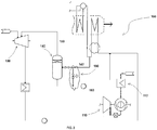
- FIGS. 1 to 7 examples of a Combined Cycle Power Plant (CCPP) 100 depicting various exemplary embodiments of the present invention incorporated therein.
- CCPP Combined Cycle Power Plant
- various associated elements may be well-known to those skilled in the art, it is not deemed necessary for purposes of acquiring an understanding of the present invention that there be recited herein all of the constructional details and explanation thereof. Rather, it is deemed sufficient to simply note that as shown in FIGS. 1 to 7 , the CCPP 100, only those components are shown that are relevant for the description of various embodiments of the present invention.
- the CCPP 100 for optimizing efficiency and output thereof includes at least one gas turbine 110, at least one heat recovery steam generator (HRSG) 120, at least one steam turbine 130, at least one flash tank 140 and first and second supply lines 150, 160.
- the at least one gas turbine 110 is thermally conjoined with the at least one steam turbine 130 via the HRSG 120 to generate the power output.
- the gas turbine 110 is configured to produce gas to generate power and subsequently releasing exhaust gas.
- the gas turbine 110 may include a gas turbine air preheating system 112 for preheating the air and supplying the heated air for enabling efficient combustion of the fuel to produce the gas in the gas turbine 110.
- the HRSG 120 is thermally connected to the at least one gas turbine 110 to use heat energy extracted from the exhaust gas of the at least one gas turbine 110 to produce steam.
- the at least one steam turbine 130 is thermally connected to the HRSG 120 to utilize the steam to generate the power output.
- the HRSG 120 is a heat exchanger which utilizes waste exhaust gas of the gas turbine 110 to produce steam for operating the steam turbine.
- the optimum utilization of heat captured in the HRSG 120 is one the major criteria to increase the CCPP 100 efficiency.
- the CCPP 100 of the present invention therefore includes the at least one flash tank 140 to optimally utilize the heat at the cold end 122 of the HRSG 120 in order to improve the CCPP 100 efficiency and power output.
- the flash tank 140 is fluidically connected, via a supply line 142, at the cold end 122 of the HRSG 120 to extract unused hot water from the cold end 122.
- a flash valve 141 may be incorporated to control extraction.
- the CCPP 100 may include a feedwater preheating system 170 thermally coupled to the cold end 122 of the HRSG 120 to maintain the temperature requirement of the feed water at the cold end 120.
- the flash tank 140 is fluidically connected at the cold end 122 of the HRSG 120 through the feedwater preheating system 170 in order to extract unused hot water of the cold end 122 via the feedwater preheating system 170.
- a recirculation system 172 may be enabled to the feedwater preheating system 170 for cooperating thereto.
- a Low Pressure (LP) drum 126 may also be operative in conjunction to the feedwater preheating system 170.
- LP Low Pressure
- the flash tank 140 having the extracted hot water may direct therefrom for being utilized in the most optimized way in order to increase the efficiency of the CCPP 100.
- the CCPP 100 includes the first and second supply lines 150, 160.
- the first supply line 150 is configured to interconnect the flash tank 140 and the steam turbine 130 to enable supply of flash steam thereto.
- the flash steam from the first supply line 150 may be injected to the steam turbine 130, more specifically, to a Low Pressure (LP) steam turbine, to generate an additional power, apart from the power generated in conventional CCPP cycle, in order to increase the efficiency and output of the CCPP 100 and thereafter is supplied back to the HRSG 120 via a return line136 through a pump 137 via passing through a condenser 135.
- LP Low Pressure
- the second supply line 160 is configured to interconnect the flash tank 140 and the gas turbine air preheating system 112 to enable supply of hot flash condensate in the flash tank 140 to the gas turbine air preheating system 112 to preheat the air to supply the preheated air to the gas turbine 110 for enabling expedite combustion.
- a pump 162 may be configured in the second supply line 160 to achieve the target.
- the cold condensate therefrom may be returned to the return line 136 and resupplied to the HRSG 120 for reoperation.
- the second supply line 160 enables the provision of preheating the air supplied in the gas turbine 110, thereby replacing the requirement of external source to preheat the fuel air in turn increasing the efficiency of the CCPP 100.
- the said provision of air preheating of the present invention precludes complex piping and heat exchanger arrangements as required in the conventional CCPP, making the present system simple and cost effective.
- FIGS. 2 to 7 depict various such variants of the CCPP 100, and will be described herein in conjunction to FIG. 1 .
- FIGS. 2 to 7 only those reference numerals with corresponding components are inserted where the variant are depicted, and the remaining components are left unnumbered in order to highlight the various variant, and that the all unnumbered components shall be read or referred from FIG. 1 .
- the CCPP 100 may include a first bypass member 180 to selectively bypass a part or all of the flash condensate from the second supply line 160 for bypassing the gas turbine air preheating system 112.
- the CCPP 100 may include a second bypass member 190 to selectively bypass a part or all of the extracted hot water from the cold end 122 for bypassing the supply of the extracted hot water in to the flash tank 140.
- This serve as a recirculation system for heating the condensate to the HRSG 120 to achieve a required minimum HRSG inlet temperature.
- the recirculation system 172 may be precluded, as shown in FIG. 3 .
- the CCPP 100 may include at least one additional heat source 200 fluidically connected the flash tank 140 to be utilized for additional hot water extraction to be supplied to the flash tank 140.
- the additional heat source 200 may include condensate return from a carbon capture unit or a district heating unit.
- the additional heating source may be any other as known in the art.
- the CCPP 100 may include a fuel gas preheating system 300 configured to heat fuel to be supplied to the gas turbine 110 for effective combustion.
- the fuel gas preheating system 300 is adapted to be configured in the second supply line 160 to utilize the heat from the hot flash condensate to preheat the fuel to be supplied to the gas turbine 110.
- at least one heat exchanger such as 310, may be configured in series with a heat exchanger 320 of the second supply line 160 for enabling the heat to be supplied to preheat the fuel gas at the fuel gas preheating system 300 as and when required full temperature, normally 150-300°C, is not generated by the hot flash condensate of the second supply line 160.
- the CCPP 100 may include a plurality of flash tanks 140 as against one flash tank 140.
- the plurality of flash tanks 140 is adapted to work in cascading configuration, using as hot source the hot water from the cold end 122 of the HRSG 120, flashing at different pressures and subsequently injecting the flash steam of varying pressure levels to corresponding steam turbine stages
- At least one heat exchanger 400 adapted to be configured to the second supply line 160.
- the at least one heat exchanger 400 is configured in an intermediate heat transfer loop 420 with the gas turbine air preheating system 112 for preheating the air supplied in the gas turbine 110.
- the at least one gas turbine 110 may preclude the gas turbine air preheating system 112 as provided in the above embodiments. Rather in this embodiment, the second supply line 160 is configured to supply hot flash condensate from the at least one flash tank 140 to the return line 136 to the at least one heat recovery steam generator 120 or to the feedwater preheating system 170.Valaves 141may be configured to control respective supply of the hot water and condensate.
- the present invention is advantageous in various scopes. This provides an improved CCPP, which may capture the heat in the HRSG, especially, at the cold end of the HRSG that may be left unused in most optimal way in order to improve CCPP efficiency and output. Further, the CCPP with such variants is convenient to use and economical. Various other advantages and features of the present invention are apparent from the above detailed description and appendage claims.
Landscapes
- Engineering & Computer Science (AREA)
- Chemical & Material Sciences (AREA)
- Combustion & Propulsion (AREA)
- Mechanical Engineering (AREA)
- General Engineering & Computer Science (AREA)
- Engine Equipment That Uses Special Cycles (AREA)
Claims (9)
- Kombikraftwerk 100, umfassend:mindestens eine Gasturbine 110, die konfiguriert ist, um Gas zur Stromerzeugung zu erzeugen und anschließend Abgas freizusetzen;mindestens einen Abhitzedampferzeuger 120, der thermisch mit der mindestens einen Gasturbine 110 verbunden ist, um die dem Abgas der mindestens einen Gasturbine 110 entzogene Wärmeenergie zu nutzen, um Dampf zu erzeugen;mindestens eine Dampfturbine 130, die thermisch mit dem mindestens einen Abhitzedampferzeuger 120 verbunden ist, um den durch den mindestens einen Abhitzedampferzeuger 120 erzeugten Dampf zu nutzen, um Strom zu erzeugen;dadurch gekennzeichnet, dass mindestens ein
Entspannungsbehälter 140 fluidisch mit einem kalten Ende 122 des mindestens einen Abhitzedampferzeugers 120 verbunden ist, um Heißwasser aus dem kalten Ende 122 zu entnehmen;eine erste Zuleitung 150 den mindestens einen Entspannungsbehälter 140 und die mindestens eine Dampfturbine 130 verbindet, um die Zufuhr von Entspannungsdampf zu der mindestens einen Dampfturbine 130 zu ermöglichen; undeine zweite Zuleitung 160 konfiguriert ist, um heißes
Entspannungskondensat aus dem mindestens einen Entspannungsbehälter 140 einer Rückführleitung zu dem mindestens einen Abhitzedampferzeuger 120 zuzuführen. - Kombikraftwerk 100 nach Anspruch 1, wobei
die Gasturbine 110 konfiguriert ist, um erwärmte Luft von einem Gasturbinenluftvorwärmsystem 112 zu empfangen, um eine effiziente Verbrennung von Brennstoff zum Erzeugen des Gases zu ermöglichen;
und wobei die zweite Zuleitung 160 den mindestens einen Entspannungsbehälter 140 und das Gasturbinenluftvorwärmsystem 112 miteinander verbindet, um die Zufuhr von heißem Entspannungskondensat zum Gasturbinenluftvorwärmsystem 112 zu ermöglichen. - Kombikraftwerk 100 nach Anspruch 2, ferner umfassend ein Speisewasservorwärmsystem 170, das thermisch mit dem kalten Ende 122 des mindestens einen Abhitzedampferzeugers 120 gekoppelt ist, um die Temperaturanforderung von Speisewasser am kalten Ende 122 aufrechtzuerhalten, wobei das Speisewasser, das als das Heißwasser dient, aus dem Speisewasservorwärmsystem 170 entnommen wird.
- Kombikraftwerk 100 nach Anspruch 2, ferner umfassend ein erstes Umgehungselement 180, um einen Teil des oder das gesamte Entspannungskondensat aus der zweiten Zuleitung 160 umzuleiten und so das Gasturbinenluftvorwärmsystem 112 zu umgehen.
- Kombikraftwerk 100 nach Anspruch 2, ferner umfassend ein zweites Umgehungselement 190, um einen Teil des oder das gesamte entnommene Heißwasser aus dem kalten Ende 122 umzuleiten und so die Zufuhr des entnommenen Heißwassers in den mindestens einen Entspannungsbehälter 140 zu umgehen und um als Rezirkulationssystem zum Erwärmen des Kondensats an dem mindestens einen Abhitzedampferzeuger 120 zu dienen, um eine erforderliche Mindesttemperatur zu erreichen.
- Kombikraftwerk 100 nach Anspruch 2, ferner umfassend ein Brenngasvorwärmsystem 300, das konfiguriert ist, um den der mindestens einen Gasturbine 110 zuzuführenden Brennstoff zur effektiven Verbrennung zu erwärmen, wobei das Brenngasvorwärmsystem 300 so ausgelegt ist, dass es in der zweiten Zuleitung 160 konfiguriert ist, um die Wärme aus dem heißen Entspannungskondensat zu nutzen, um den der mindestens einen Gasturbine 110 zuzuführenden Brennstoff vorzuwärmen.
- Kombikraftwerk 100 nach Anspruch 2, wobei der mindestens eine Entspannungsbehälter 140 so ausgelegt ist, dass er eine Vielzahl von Entspannungsbehältern mit unterschiedlichen Druckstufen zur Heißwasserentnahme und zum anschließenden Einspritzen des Entspannungsdampfs mit unterschiedlichen Druckstufen in eine entsprechende Dampfturbinenstufe umfasst.
- Kombikraftwerk 100 nach Anspruch 7, wobei die mindestens eine Dampfturbine 130 eine mehrstufige Dampfturbine ist, wobei die erste Zuleitung 150 konfiguriert ist, um den Entspannungsdampf unterschiedlicher Druckstufen den entsprechenden Dampfturbinenstufen zuzuführen.
- Kombikraftwerk 100 nach Anspruch 2, ferner umfassend mindestens einen Wärmetauscher 400, der so ausgelegt ist, dass er für die zweite Zuleitung 160 konfiguriert ist, wobei der mindestens eine Wärmetauscher 400 in einer Wärmeübertragungszwischenschleife 420 zum Gasturbinenluftvorwärmsystem 112 zum Vorwärmen der im Gasturbinentriebwerk 110 zugeführten Luft konfiguriert ist.
Priority Applications (1)
| Application Number | Priority Date | Filing Date | Title |
|---|---|---|---|
| EP14190310.4A EP2937528B1 (de) | 2013-10-31 | 2014-10-24 | Kombikraftwerk mit verbessertem Wirkungsgrad |
Applications Claiming Priority (2)
| Application Number | Priority Date | Filing Date | Title |
|---|---|---|---|
| EP13191037 | 2013-10-31 | ||
| EP14190310.4A EP2937528B1 (de) | 2013-10-31 | 2014-10-24 | Kombikraftwerk mit verbessertem Wirkungsgrad |
Publications (2)
| Publication Number | Publication Date |
|---|---|
| EP2937528A1 EP2937528A1 (de) | 2015-10-28 |
| EP2937528B1 true EP2937528B1 (de) | 2021-08-11 |
Family
ID=49517321
Family Applications (1)
| Application Number | Title | Priority Date | Filing Date |
|---|---|---|---|
| EP14190310.4A Active EP2937528B1 (de) | 2013-10-31 | 2014-10-24 | Kombikraftwerk mit verbessertem Wirkungsgrad |
Country Status (3)
| Country | Link |
|---|---|
| US (2) | US10914200B2 (de) |
| EP (1) | EP2937528B1 (de) |
| KR (1) | KR102326406B1 (de) |
Families Citing this family (9)
| Publication number | Priority date | Publication date | Assignee | Title |
|---|---|---|---|---|
| EP2824293A1 (de) * | 2013-07-08 | 2015-01-14 | Alstom Technology Ltd | Kraftwerk mit integrierter Brenngasvorerwärmung |
| JP2017040201A (ja) * | 2015-08-19 | 2017-02-23 | 株式会社東芝 | 発電システムおよびその運転方法 |
| US11603794B2 (en) | 2015-12-30 | 2023-03-14 | Leonard Morgensen Andersen | Method and apparatus for increasing useful energy/thrust of a gas turbine engine by one or more rotating fluid moving (agitator) pieces due to formation of a defined steam region |
| EP3219940B1 (de) | 2016-03-18 | 2023-01-11 | General Electric Technology GmbH | Kombikraftwerk und verfahren zum betrieb solch eines kombikraftwerks |
| CN107387182B (zh) * | 2017-09-04 | 2023-06-20 | 中国电力工程顾问集团西南电力设计院有限公司 | 一种背压式汽轮机启动排汽回收系统 |
| EP3486440B1 (de) * | 2017-11-21 | 2022-11-09 | Siemens Energy Global GmbH & Co. KG | Abhitzedampfgenerator, verfahren zum erzeugen von dampf für eine dampfturbine und system mit einer dampfturbine und einem wärmerückgewinnungsdampfgenerator |
| JP2019190359A (ja) * | 2018-04-24 | 2019-10-31 | 三菱重工エンジニアリング株式会社 | プラント及び燃焼排ガス処理方法 |
| US11286208B2 (en) * | 2018-08-21 | 2022-03-29 | General Electric Company | Systems and methods for thermally processing CMC components |
| CN109595044B (zh) * | 2018-11-29 | 2022-03-08 | 浙江海洋大学 | 一种船舶主机废气余热照明装置 |
Family Cites Families (22)
| Publication number | Priority date | Publication date | Assignee | Title |
|---|---|---|---|---|
| US4402183A (en) | 1981-11-19 | 1983-09-06 | General Electric Company | Sliding pressure flash tank |
| US5083423A (en) * | 1989-01-11 | 1992-01-28 | Stewart & Stevenson Services, Inc. | Apparatus and method for optimizing the air inlet temperature of gas turbines |
| DE59205446D1 (de) * | 1991-07-17 | 1996-04-04 | Siemens Ag | Verfahren zum Betreiben einer Gas- und Dampfturbinenanlage und Anlage zur Durchführung des Verfahrens |
| DE4237665A1 (de) * | 1992-11-07 | 1994-05-11 | Asea Brown Boveri | Verfahren zum Betrieb einer Kombianlage |
| US5904039A (en) * | 1995-05-15 | 1999-05-18 | Siemens Aktiengesellschaft | Method and configuration for deaerating a condensate |
| US5647199A (en) * | 1995-09-12 | 1997-07-15 | General Electric Co. | Combined-cycle with multi-pressure reheat system |
| DE19545668A1 (de) * | 1995-12-07 | 1997-06-12 | Asea Brown Boveri | Verfahren zum Betrieb einer mit einem Abhitzedampferzeuger und einem Dampfverbraucher kombinierten Gasturbogruppe |
| DE19609912A1 (de) * | 1996-03-14 | 1997-09-18 | Asea Brown Boveri | Verfahren zum Betrieb einer Kraftwerksanlage |
| DE19720881A1 (de) * | 1997-05-17 | 1998-11-19 | Asea Brown Boveri | Kombikraftwerk mit Kraftwärmekopplung |
| EP1243757B1 (de) * | 1997-07-25 | 2005-12-07 | ALSTOM Technology Ltd | Verfahren zum Betrieb einer Kraftwerksanlage |
| JP3897891B2 (ja) * | 1998-01-19 | 2007-03-28 | 株式会社東芝 | コンバインドサイクル発電プラント |
| DE19837251C1 (de) * | 1998-08-17 | 2000-02-10 | Siemens Ag | Gas- und Dampfturbinenanlage |
| DE19944920B4 (de) * | 1999-09-20 | 2013-11-21 | Alstom Technology Ltd. | Kombikraftwerk mit Einspritzvorrichtung zum Einspritzen von Wasser in den Frischdampf |
| JP2003161164A (ja) | 2001-11-26 | 2003-06-06 | Hitachi Ltd | コンバインドサイクル発電プラント |
| EP1682750B1 (de) * | 2003-10-30 | 2012-11-28 | Alstom Technology Ltd | Kraftwerksanlage |
| AT7761U1 (de) | 2004-04-01 | 2005-08-25 | Pr Rohrleitungs Und Anlagenbau | Verfahren und einrichtung zur erzeugung von kraft und wärme |
| KR100774546B1 (ko) * | 2006-11-13 | 2007-11-08 | 두산중공업 주식회사 | 배열회수 증기발생기의 방출수를 이용한 해수 담수화기 |
| EP2256316A1 (de) * | 2009-05-28 | 2010-12-01 | Siemens Aktiengesellschaft | Ansauglufttemperiereinrichtung sowie ein Verfahren zum Betrieb einer Ansauglufttemperiereinrichtung |
| IT1397210B1 (it) * | 2009-12-29 | 2013-01-04 | Ansaldo Energia Spa | Impianto a ciclo combinato per la produzione di energia elettrica ed energia termica e metodo di funzionamento di tale impianto |
| US8539750B2 (en) | 2010-04-30 | 2013-09-24 | Siemens Energy, Inc. | Energy recovery and steam supply for power augmentation in a combined cycle power generation system |
| US8813471B2 (en) | 2011-06-29 | 2014-08-26 | General Electric Company | System for fuel gas moisturization and heating |
| US9284857B2 (en) * | 2012-06-26 | 2016-03-15 | The Regents Of The University Of California | Organic flash cycles for efficient power production |
-
2014
- 2014-10-24 EP EP14190310.4A patent/EP2937528B1/de active Active
- 2014-10-24 US US14/523,085 patent/US10914200B2/en active Active
- 2014-10-29 KR KR1020140147980A patent/KR102326406B1/ko active Active
-
2021
- 2021-02-08 US US17/170,266 patent/US11655736B2/en active Active
Also Published As
| Publication number | Publication date |
|---|---|
| US20210180473A1 (en) | 2021-06-17 |
| CN104595031A (zh) | 2015-05-06 |
| US20150113939A1 (en) | 2015-04-30 |
| KR20150050443A (ko) | 2015-05-08 |
| US11655736B2 (en) | 2023-05-23 |
| KR102326406B1 (ko) | 2021-11-17 |
| US10914200B2 (en) | 2021-02-09 |
| EP2937528A1 (de) | 2015-10-28 |
Similar Documents
| Publication | Publication Date | Title |
|---|---|---|
| US11655736B2 (en) | Combined cycle power plant with improved efficiency | |
| RU2532635C2 (ru) | Аккумуляция электроэнергии тепловым аккумулятором и обратное получение электроэнергии посредством термодинамического кругового процесса | |
| CN104279058B (zh) | 联合循环发电设备以及操作联合循环发电设备的方法 | |
| EP1752617A2 (de) | Kraftwerk mit kombiniertem Zyklus | |
| US20080034757A1 (en) | Method and system integrating solar heat into a regenerative rankine cycle | |
| EP2846008B1 (de) | Dampfturbinenanlage | |
| US20110131996A1 (en) | Latent Heat Recovery Generator System | |
| US10288279B2 (en) | Flue gas heat recovery integration | |
| CN203099962U (zh) | 热电厂循环水直接供暖系统 | |
| US8205451B2 (en) | System and assemblies for pre-heating fuel in a combined cycle power plant | |
| KR101584418B1 (ko) | 보일러 플랜트 | |
| CN109312635B (zh) | 冷凝物再循环 | |
| SK6120Y1 (sk) | Method and system for processing of flue gas heat source | |
| CN102494329B (zh) | 锅炉烟气余热综合利用装置 | |
| CN105889896A (zh) | 一种机炉协调节能系统 | |
| RU2580848C1 (ru) | Теплофикационная турбоустановка | |
| EP2868872B1 (de) | Speisewasservorwärmungssystem und -verfahren | |
| CZ304409B6 (cs) | Energetický zdroj s paroplynovou turbínou a parogenerátorem | |
| CN104595031B (zh) | 具有改善的效率的联合循环发电厂 | |
| RU122124U1 (ru) | Тепловая электрическая станция с теплонасосной установкой | |
| CZ25472U1 (cs) | Energetický zdroj s paroplynovou turbínou a parogenerátorem | |
| CZ24220U1 (cs) | Zapojení tepelného čerpadla do systému energetického kondenzačního parního stroje s využitím pro tepelnou regeneraci napájecí vody, ohřev topné vody pro komunální vytápění a chlazení chladicího média v systémech energetických kondenzačních parních strojů |
Legal Events
| Date | Code | Title | Description |
|---|---|---|---|
| PUAI | Public reference made under article 153(3) epc to a published international application that has entered the european phase |
Free format text: ORIGINAL CODE: 0009012 |
|
| AK | Designated contracting states |
Kind code of ref document: A1 Designated state(s): AL AT BE BG CH CY CZ DE DK EE ES FI FR GB GR HR HU IE IS IT LI LT LU LV MC MK MT NL NO PL PT RO RS SE SI SK SM TR |
|
| AX | Request for extension of the european patent |
Extension state: BA ME |
|
| 17P | Request for examination filed |
Effective date: 20160428 |
|
| RBV | Designated contracting states (corrected) |
Designated state(s): AL AT BE BG CH CY CZ DE DK EE ES FI FR GB GR HR HU IE IS IT LI LT LU LV MC MK MT NL NO PL PT RO RS SE SI SK SM TR |
|
| RAP1 | Party data changed (applicant data changed or rights of an application transferred) |
Owner name: GENERAL ELECTRIC TECHNOLOGY GMBH |
|
| GRAP | Despatch of communication of intention to grant a patent |
Free format text: ORIGINAL CODE: EPIDOSNIGR1 |
|
| STAA | Information on the status of an ep patent application or granted ep patent |
Free format text: STATUS: GRANT OF PATENT IS INTENDED |
|
| INTG | Intention to grant announced |
Effective date: 20210309 |
|
| RAP3 | Party data changed (applicant data changed or rights of an application transferred) |
Owner name: GENERAL ELECTRIC TECHNOLOGY GMBH |
|
| GRAS | Grant fee paid |
Free format text: ORIGINAL CODE: EPIDOSNIGR3 |
|
| GRAA | (expected) grant |
Free format text: ORIGINAL CODE: 0009210 |
|
| STAA | Information on the status of an ep patent application or granted ep patent |
Free format text: STATUS: THE PATENT HAS BEEN GRANTED |
|
| AK | Designated contracting states |
Kind code of ref document: B1 Designated state(s): AL AT BE BG CH CY CZ DE DK EE ES FI FR GB GR HR HU IE IS IT LI LT LU LV MC MK MT NL NO PL PT RO RS SE SI SK SM TR |
|
| REG | Reference to a national code |
Ref country code: GB Ref legal event code: FG4D |
|
| REG | Reference to a national code |
Ref country code: CH Ref legal event code: EP |
|
| REG | Reference to a national code |
Ref country code: DE Ref legal event code: R096 Ref document number: 602014079332 Country of ref document: DE |
|
| REG | Reference to a national code |
Ref country code: IE Ref legal event code: FG4D Ref country code: AT Ref legal event code: REF Ref document number: 1419597 Country of ref document: AT Kind code of ref document: T Effective date: 20210915 |
|
| REG | Reference to a national code |
Ref country code: LT Ref legal event code: MG9D |
|
| REG | Reference to a national code |
Ref country code: NL Ref legal event code: MP Effective date: 20210811 |
|
| REG | Reference to a national code |
Ref country code: AT Ref legal event code: MK05 Ref document number: 1419597 Country of ref document: AT Kind code of ref document: T Effective date: 20210811 |
|
| PG25 | Lapsed in a contracting state [announced via postgrant information from national office to epo] |
Ref country code: BG Free format text: LAPSE BECAUSE OF FAILURE TO SUBMIT A TRANSLATION OF THE DESCRIPTION OR TO PAY THE FEE WITHIN THE PRESCRIBED TIME-LIMIT Effective date: 20211111 Ref country code: AT Free format text: LAPSE BECAUSE OF FAILURE TO SUBMIT A TRANSLATION OF THE DESCRIPTION OR TO PAY THE FEE WITHIN THE PRESCRIBED TIME-LIMIT Effective date: 20210811 Ref country code: LT Free format text: LAPSE BECAUSE OF FAILURE TO SUBMIT A TRANSLATION OF THE DESCRIPTION OR TO PAY THE FEE WITHIN THE PRESCRIBED TIME-LIMIT Effective date: 20210811 Ref country code: NO Free format text: LAPSE BECAUSE OF FAILURE TO SUBMIT A TRANSLATION OF THE DESCRIPTION OR TO PAY THE FEE WITHIN THE PRESCRIBED TIME-LIMIT Effective date: 20211111 Ref country code: PT Free format text: LAPSE BECAUSE OF FAILURE TO SUBMIT A TRANSLATION OF THE DESCRIPTION OR TO PAY THE FEE WITHIN THE PRESCRIBED TIME-LIMIT Effective date: 20211213 Ref country code: FI Free format text: LAPSE BECAUSE OF FAILURE TO SUBMIT A TRANSLATION OF THE DESCRIPTION OR TO PAY THE FEE WITHIN THE PRESCRIBED TIME-LIMIT Effective date: 20210811 Ref country code: ES Free format text: LAPSE BECAUSE OF FAILURE TO SUBMIT A TRANSLATION OF THE DESCRIPTION OR TO PAY THE FEE WITHIN THE PRESCRIBED TIME-LIMIT Effective date: 20210811 Ref country code: HR Free format text: LAPSE BECAUSE OF FAILURE TO SUBMIT A TRANSLATION OF THE DESCRIPTION OR TO PAY THE FEE WITHIN THE PRESCRIBED TIME-LIMIT Effective date: 20210811 Ref country code: RS Free format text: LAPSE BECAUSE OF FAILURE TO SUBMIT A TRANSLATION OF THE DESCRIPTION OR TO PAY THE FEE WITHIN THE PRESCRIBED TIME-LIMIT Effective date: 20210811 Ref country code: SE Free format text: LAPSE BECAUSE OF FAILURE TO SUBMIT A TRANSLATION OF THE DESCRIPTION OR TO PAY THE FEE WITHIN THE PRESCRIBED TIME-LIMIT Effective date: 20210811 |
|
| PG25 | Lapsed in a contracting state [announced via postgrant information from national office to epo] |
Ref country code: PL Free format text: LAPSE BECAUSE OF FAILURE TO SUBMIT A TRANSLATION OF THE DESCRIPTION OR TO PAY THE FEE WITHIN THE PRESCRIBED TIME-LIMIT Effective date: 20210811 Ref country code: LV Free format text: LAPSE BECAUSE OF FAILURE TO SUBMIT A TRANSLATION OF THE DESCRIPTION OR TO PAY THE FEE WITHIN THE PRESCRIBED TIME-LIMIT Effective date: 20210811 Ref country code: GR Free format text: LAPSE BECAUSE OF FAILURE TO SUBMIT A TRANSLATION OF THE DESCRIPTION OR TO PAY THE FEE WITHIN THE PRESCRIBED TIME-LIMIT Effective date: 20211112 |
|
| PG25 | Lapsed in a contracting state [announced via postgrant information from national office to epo] |
Ref country code: NL Free format text: LAPSE BECAUSE OF FAILURE TO SUBMIT A TRANSLATION OF THE DESCRIPTION OR TO PAY THE FEE WITHIN THE PRESCRIBED TIME-LIMIT Effective date: 20210811 |
|
| PG25 | Lapsed in a contracting state [announced via postgrant information from national office to epo] |
Ref country code: DK Free format text: LAPSE BECAUSE OF FAILURE TO SUBMIT A TRANSLATION OF THE DESCRIPTION OR TO PAY THE FEE WITHIN THE PRESCRIBED TIME-LIMIT Effective date: 20210811 |
|
| REG | Reference to a national code |
Ref country code: DE Ref legal event code: R097 Ref document number: 602014079332 Country of ref document: DE |
|
| PG25 | Lapsed in a contracting state [announced via postgrant information from national office to epo] |
Ref country code: SM Free format text: LAPSE BECAUSE OF FAILURE TO SUBMIT A TRANSLATION OF THE DESCRIPTION OR TO PAY THE FEE WITHIN THE PRESCRIBED TIME-LIMIT Effective date: 20210811 Ref country code: SK Free format text: LAPSE BECAUSE OF FAILURE TO SUBMIT A TRANSLATION OF THE DESCRIPTION OR TO PAY THE FEE WITHIN THE PRESCRIBED TIME-LIMIT Effective date: 20210811 Ref country code: RO Free format text: LAPSE BECAUSE OF FAILURE TO SUBMIT A TRANSLATION OF THE DESCRIPTION OR TO PAY THE FEE WITHIN THE PRESCRIBED TIME-LIMIT Effective date: 20210811 Ref country code: EE Free format text: LAPSE BECAUSE OF FAILURE TO SUBMIT A TRANSLATION OF THE DESCRIPTION OR TO PAY THE FEE WITHIN THE PRESCRIBED TIME-LIMIT Effective date: 20210811 Ref country code: CZ Free format text: LAPSE BECAUSE OF FAILURE TO SUBMIT A TRANSLATION OF THE DESCRIPTION OR TO PAY THE FEE WITHIN THE PRESCRIBED TIME-LIMIT Effective date: 20210811 Ref country code: AL Free format text: LAPSE BECAUSE OF FAILURE TO SUBMIT A TRANSLATION OF THE DESCRIPTION OR TO PAY THE FEE WITHIN THE PRESCRIBED TIME-LIMIT Effective date: 20210811 |
|
| REG | Reference to a national code |
Ref country code: CH Ref legal event code: PL |
|
| PLBE | No opposition filed within time limit |
Free format text: ORIGINAL CODE: 0009261 |
|
| STAA | Information on the status of an ep patent application or granted ep patent |
Free format text: STATUS: NO OPPOSITION FILED WITHIN TIME LIMIT |
|
| REG | Reference to a national code |
Ref country code: BE Ref legal event code: MM Effective date: 20211031 |
|
| PG25 | Lapsed in a contracting state [announced via postgrant information from national office to epo] |
Ref country code: MC Free format text: LAPSE BECAUSE OF FAILURE TO SUBMIT A TRANSLATION OF THE DESCRIPTION OR TO PAY THE FEE WITHIN THE PRESCRIBED TIME-LIMIT Effective date: 20210811 |
|
| 26N | No opposition filed |
Effective date: 20220512 |
|
| GBPC | Gb: european patent ceased through non-payment of renewal fee |
Effective date: 20211111 |
|
| PG25 | Lapsed in a contracting state [announced via postgrant information from national office to epo] |
Ref country code: LU Free format text: LAPSE BECAUSE OF NON-PAYMENT OF DUE FEES Effective date: 20211024 Ref country code: BE Free format text: LAPSE BECAUSE OF NON-PAYMENT OF DUE FEES Effective date: 20211031 |
|
| PG25 | Lapsed in a contracting state [announced via postgrant information from national office to epo] |
Ref country code: SI Free format text: LAPSE BECAUSE OF FAILURE TO SUBMIT A TRANSLATION OF THE DESCRIPTION OR TO PAY THE FEE WITHIN THE PRESCRIBED TIME-LIMIT Effective date: 20210811 Ref country code: LI Free format text: LAPSE BECAUSE OF NON-PAYMENT OF DUE FEES Effective date: 20211031 Ref country code: CH Free format text: LAPSE BECAUSE OF NON-PAYMENT OF DUE FEES Effective date: 20211031 |
|
| PG25 | Lapsed in a contracting state [announced via postgrant information from national office to epo] |
Ref country code: FR Free format text: LAPSE BECAUSE OF NON-PAYMENT OF DUE FEES Effective date: 20211031 |
|
| PG25 | Lapsed in a contracting state [announced via postgrant information from national office to epo] |
Ref country code: IE Free format text: LAPSE BECAUSE OF NON-PAYMENT OF DUE FEES Effective date: 20211024 Ref country code: GB Free format text: LAPSE BECAUSE OF NON-PAYMENT OF DUE FEES Effective date: 20211111 |
|
| PG25 | Lapsed in a contracting state [announced via postgrant information from national office to epo] |
Ref country code: HU Free format text: LAPSE BECAUSE OF FAILURE TO SUBMIT A TRANSLATION OF THE DESCRIPTION OR TO PAY THE FEE WITHIN THE PRESCRIBED TIME-LIMIT; INVALID AB INITIO Effective date: 20141024 |
|
| P01 | Opt-out of the competence of the unified patent court (upc) registered |
Effective date: 20230522 |
|
| PG25 | Lapsed in a contracting state [announced via postgrant information from national office to epo] |
Ref country code: CY Free format text: LAPSE BECAUSE OF FAILURE TO SUBMIT A TRANSLATION OF THE DESCRIPTION OR TO PAY THE FEE WITHIN THE PRESCRIBED TIME-LIMIT Effective date: 20210811 |
|
| PG25 | Lapsed in a contracting state [announced via postgrant information from national office to epo] |
Ref country code: MK Free format text: LAPSE BECAUSE OF FAILURE TO SUBMIT A TRANSLATION OF THE DESCRIPTION OR TO PAY THE FEE WITHIN THE PRESCRIBED TIME-LIMIT Effective date: 20210811 |
|
| PG25 | Lapsed in a contracting state [announced via postgrant information from national office to epo] |
Ref country code: MT Free format text: LAPSE BECAUSE OF FAILURE TO SUBMIT A TRANSLATION OF THE DESCRIPTION OR TO PAY THE FEE WITHIN THE PRESCRIBED TIME-LIMIT Effective date: 20210811 |
|
| PGFP | Annual fee paid to national office [announced via postgrant information from national office to epo] |
Ref country code: IT Payment date: 20250923 Year of fee payment: 12 |
|
| PG25 | Lapsed in a contracting state [announced via postgrant information from national office to epo] |
Ref country code: TR Free format text: LAPSE BECAUSE OF FAILURE TO SUBMIT A TRANSLATION OF THE DESCRIPTION OR TO PAY THE FEE WITHIN THE PRESCRIBED TIME-LIMIT Effective date: 20210811 |
|
| PGFP | Annual fee paid to national office [announced via postgrant information from national office to epo] |
Ref country code: DE Payment date: 20250923 Year of fee payment: 12 |