EP2937603A1 - Kugelventil - Google Patents
Kugelventil Download PDFInfo
- Publication number
- EP2937603A1 EP2937603A1 EP14290115.6A EP14290115A EP2937603A1 EP 2937603 A1 EP2937603 A1 EP 2937603A1 EP 14290115 A EP14290115 A EP 14290115A EP 2937603 A1 EP2937603 A1 EP 2937603A1
- Authority
- EP
- European Patent Office
- Prior art keywords
- spherical valve
- seal
- movable
- valve
- movable seal
- Prior art date
- Legal status (The legal status is an assumption and is not a legal conclusion. Google has not performed a legal analysis and makes no representation as to the accuracy of the status listed.)
- Withdrawn
Links
- 239000012530 fluid Substances 0.000 claims abstract description 36
- XLYOFNOQVPJJNP-UHFFFAOYSA-N water Substances O XLYOFNOQVPJJNP-UHFFFAOYSA-N 0.000 claims description 15
- 239000002131 composite material Substances 0.000 claims description 6
- 239000007769 metal material Substances 0.000 claims description 6
- 239000000463 material Substances 0.000 claims description 3
- 239000004033 plastic Substances 0.000 claims description 3
- 239000010935 stainless steel Substances 0.000 claims description 3
- 229910001220 stainless steel Inorganic materials 0.000 claims description 3
- JRBRVDCKNXZZGH-UHFFFAOYSA-N alumane;copper Chemical compound [AlH3].[Cu] JRBRVDCKNXZZGH-UHFFFAOYSA-N 0.000 claims description 2
- 238000007789 sealing Methods 0.000 abstract description 24
- 238000011144 upstream manufacturing Methods 0.000 description 31
- 238000001514 detection method Methods 0.000 description 5
- 230000000903 blocking effect Effects 0.000 description 3
- 238000012544 monitoring process Methods 0.000 description 2
- 230000002441 reversible effect Effects 0.000 description 2
- 229910000975 Carbon steel Inorganic materials 0.000 description 1
- 208000027418 Wounds and injury Diseases 0.000 description 1
- 239000010962 carbon steel Substances 0.000 description 1
- 230000007797 corrosion Effects 0.000 description 1
- 238000005260 corrosion Methods 0.000 description 1
- 230000006378 damage Effects 0.000 description 1
- 230000001939 inductive effect Effects 0.000 description 1
- 208000014674 injury Diseases 0.000 description 1
- 238000012986 modification Methods 0.000 description 1
- 230000004048 modification Effects 0.000 description 1
Images


Classifications
-
- F—MECHANICAL ENGINEERING; LIGHTING; HEATING; WEAPONS; BLASTING
- F16—ENGINEERING ELEMENTS AND UNITS; GENERAL MEASURES FOR PRODUCING AND MAINTAINING EFFECTIVE FUNCTIONING OF MACHINES OR INSTALLATIONS; THERMAL INSULATION IN GENERAL
- F16J—PISTONS; CYLINDERS; SEALINGS
- F16J15/00—Sealings
- F16J15/46—Sealings with packing ring expanded or pressed into place by fluid pressure, e.g. inflatable packings
- F16J15/48—Sealings with packing ring expanded or pressed into place by fluid pressure, e.g. inflatable packings influenced by the pressure within the member to be sealed
-
- F—MECHANICAL ENGINEERING; LIGHTING; HEATING; WEAPONS; BLASTING
- F16—ENGINEERING ELEMENTS AND UNITS; GENERAL MEASURES FOR PRODUCING AND MAINTAINING EFFECTIVE FUNCTIONING OF MACHINES OR INSTALLATIONS; THERMAL INSULATION IN GENERAL
- F16K—VALVES; TAPS; COCKS; ACTUATING-FLOATS; DEVICES FOR VENTING OR AERATING
- F16K5/00—Plug valves; Taps or cocks comprising only cut-off apparatus having at least one of the sealing faces shaped as a more or less complete surface of a solid of revolution, the opening and closing movement being predominantly rotary
- F16K5/08—Details
- F16K5/14—Special arrangements for separating the sealing faces or for pressing them together
- F16K5/20—Special arrangements for separating the sealing faces or for pressing them together for plugs with spherical surfaces
- F16K5/205—Sealing effected by the flowing medium
- F16K5/208—Sealing effected by the flowing medium with tongue-shaped means
Definitions
- the present invention relates to a spherical valve integrated in a fluid distribution system, such that the spherical valve allows interrupting or enabling the fluid circulation in a selective way.
- Fluid distribution systems with hydraulic machines typically comprise a valve upstream of the hydraulic machine, allowing the control of the flow of fluid through the hydraulic machine, by authorizing or interrupting this flow.
- a valve typically comprises a rotating blocking member that is operated by a control device: the control device acts on the blocking member, making it rotate in one or in another sense of rotation, so that this alternatively authorizes or interrupts the flow of fluid.
- These valves are typically of the spherical type, where the blocking member has the shape of a sphere.
- spherical valves are changed from an open position, authorizing the fluid to flow through, into a closed position, where they must avoid any flow of fluid through.
- spherical valves comprise movable seals that need to properly and effectively close the flow of fluid in the cited closed position.
- the spherical valves comprise movable seals made of metallic ring that, by water pressure, are pressed all around corresponding seats in these valves.
- the present invention relates to a spherical valve integrated in a fluid distribution system, this spherical valve allowing interrupting or enabling the fluid circulation in a selective way.
- the spherical valve comprises a sealing system, able to rotate and alternate from a closed into an open position: in the closed position, the sealing system rests in a tight way onto valve contact seats, stopping the flow of fluid through the spherical valve; in the open position, the flow of fluid in the spherical valve is allowed.
- the sealing system in the spherical valve of the invention comprises:
- the main functions of the system of the invention are the following:
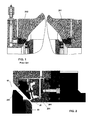
- the present invention relates to a spherical valve 10 integrated in a fluid distribution system, such that the spherical valve 10 allows interrupting or enabling the fluid circulation in a selective way.
- the spherical valve 10 for hydraulic machines movable between a released position and a forward position to allow/stop a flow of a fluid
- a movable seal (201; 202), comprising a rotary central body and an elongated ring, the elongated ring having a terminal member configured to abut on the contact seats 22 when in a forward position stopping the flow of fluid.
- the valve 10 also comprises at least two facing housings configured to guide rotation of the central body.
- the elongated ring is made of a material such to be elastically deformed when an operating thrust is applied to the movable seal when in forward position.
- the spherical valve 10 comprises a sealing system 20, able to rotate and alternate from a closed into an open position: in the closed position, the sealing system 20 rests in a tight way onto valve contact seats 22, stopping the flow of fluid through the spherical valve 10; in the open position, the flow of fluid in the spherical valve 10 is allowed.
- the sealing system 20 of the invention comprises:
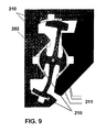
- overlays (210 and 211, as shown in Figure 9 , for downstream movable seals 201, similar ones exist for upstream movable seals 202) are provided in the first and second housings for the movable rings.
- these overlays are made of copper-aluminum or stainless steel, provided on the carbon steel surfaces of the housings of the movable rings.
- the housings can also be fully in stainless steel.
- the main functions of the spherical valve 10 of the invention are the following:
- downstream or upstream movable seals 201, 202 comprising a movable ring twisted having one extremity that is moved towards the valve contact seats 22.
- the movable ring must have a sufficient softness in order to match and adapt to the deformed shape of the valve contact seats 22.
- the movable ring must also have sufficient stiffness in order to have a limited deflection caused by water pressure.
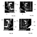
- Figures 5a, 5b, 5c and 5d show the downstream and upstream movable seals 201, 202 being released from the valve contact seats 22 or applied to the valve contact seals 22.
- the tightness is based on the deflection of the movable ring, it has a natural tendency to move back in its natural position so no energy is necessary to release the tightness.
- the movable ring In the released position (see Figures 5a and 5c ), the movable ring is submitted to the water pressure on the front side, that is, the operating effort is the thrust of the water pressure plus the friction of the radial seal.
- the movable ring In the forward or applied position (see Figures 5b and 5d ), the movable ring is submitted to the water pressure on the front side and in the operating chambers, that is, the operating effort is the thrust of the water pressure plus the necessary load to deform the ring plus the friction of the radial seal.
- the inertia around the axis XX of the movable ring must be as small as possible in order to allow the deformation of the movable ring with a low pressure: this is why the specific shape of the movable ring is designed.
- the spherical valve 10 of the invention also comprises a locking device 301 that is used to lock the upstream movable seal 202: typically, the locking device 301 comprises a cam, the rotation of which, as shown in Figure 7 , locks the upstream movable seal 202.
- the locking device 301 also comprises a screw-nut system 302 avoiding the rotation of the locking device 301 when locking the upstream movable seal 202.
- Positioning sensors for downstream 23 and upstream 24 movable seals assure the detection of the positioning of the movable ring: at least three sensors, evenly located, are used, for each one of the movable rings.
- the positioning detection of the movable rings is mandatory for safety reasons, in order to detect if the movable ring is in good positioning for the operations.
Landscapes
- Engineering & Computer Science (AREA)
- General Engineering & Computer Science (AREA)
- Mechanical Engineering (AREA)
- Physics & Mathematics (AREA)
- Architecture (AREA)
- Fluid Mechanics (AREA)
- Taps Or Cocks (AREA)
Priority Applications (3)
| Application Number | Priority Date | Filing Date | Title |
|---|---|---|---|
| EP14290115.6A EP2937603A1 (de) | 2014-04-22 | 2014-04-22 | Kugelventil |
| CN201580021092.4A CN106255848A (zh) | 2014-04-22 | 2015-04-21 | 球阀 |
| PCT/EP2015/058590 WO2015162126A1 (en) | 2014-04-22 | 2015-04-21 | Spherical valve |
Applications Claiming Priority (1)
| Application Number | Priority Date | Filing Date | Title |
|---|---|---|---|
| EP14290115.6A EP2937603A1 (de) | 2014-04-22 | 2014-04-22 | Kugelventil |
Publications (1)
| Publication Number | Publication Date |
|---|---|
| EP2937603A1 true EP2937603A1 (de) | 2015-10-28 |
Family
ID=50828837
Family Applications (1)
| Application Number | Title | Priority Date | Filing Date |
|---|---|---|---|
| EP14290115.6A Withdrawn EP2937603A1 (de) | 2014-04-22 | 2014-04-22 | Kugelventil |
Country Status (3)
| Country | Link |
|---|---|
| EP (1) | EP2937603A1 (de) |
| CN (1) | CN106255848A (de) |
| WO (1) | WO2015162126A1 (de) |
Citations (4)
| Publication number | Priority date | Publication date | Assignee | Title |
|---|---|---|---|---|
| DE1060206B (de) * | 1954-03-29 | 1959-06-25 | Albach & Co | Absperrhahn mit kugelfoermigem Kueken und elastischer Dichtung im Gehaeuseabfluss |
| DE1172914B (de) * | 1959-07-09 | 1964-06-25 | Gen Dynamics Corp | Hahn mit Kugelkueken |
| US4779841A (en) * | 1986-07-09 | 1988-10-25 | Posi-Seal International, Inc. | Assembly and method for installing and retaining valve seals |
| US20120205569A1 (en) * | 2011-02-11 | 2012-08-16 | Yeary & Associates, Inc. | Differential pressure sealing device for ball valves |
Family Cites Families (3)
| Publication number | Priority date | Publication date | Assignee | Title |
|---|---|---|---|---|
| DE202008011406U1 (de) * | 2007-12-20 | 2009-06-18 | Xomox International Gmbh & Co | Ventil |
| US8727309B2 (en) * | 2009-04-17 | 2014-05-20 | Fisher Controls International Llc | Fluid valves having adjustable sealing characteristics |
| CN201844107U (zh) * | 2010-08-05 | 2011-05-25 | 浙江盾安阀门有限公司 | 一种高压球阀密封结构 |
-
2014
- 2014-04-22 EP EP14290115.6A patent/EP2937603A1/de not_active Withdrawn
-
2015
- 2015-04-21 WO PCT/EP2015/058590 patent/WO2015162126A1/en not_active Ceased
- 2015-04-21 CN CN201580021092.4A patent/CN106255848A/zh active Pending
Patent Citations (4)
| Publication number | Priority date | Publication date | Assignee | Title |
|---|---|---|---|---|
| DE1060206B (de) * | 1954-03-29 | 1959-06-25 | Albach & Co | Absperrhahn mit kugelfoermigem Kueken und elastischer Dichtung im Gehaeuseabfluss |
| DE1172914B (de) * | 1959-07-09 | 1964-06-25 | Gen Dynamics Corp | Hahn mit Kugelkueken |
| US4779841A (en) * | 1986-07-09 | 1988-10-25 | Posi-Seal International, Inc. | Assembly and method for installing and retaining valve seals |
| US20120205569A1 (en) * | 2011-02-11 | 2012-08-16 | Yeary & Associates, Inc. | Differential pressure sealing device for ball valves |
Also Published As
| Publication number | Publication date |
|---|---|
| WO2015162126A1 (en) | 2015-10-29 |
| CN106255848A (zh) | 2016-12-21 |
Similar Documents
| Publication | Publication Date | Title |
|---|---|---|
| EP2809979B1 (de) | Durchflussregelbaugruppe mit einer drehverhinderungsbaugruppe zur verwendung mit flüssigkeitsventilen | |
| EP3058256B1 (de) | Dichtung für schwimmendes kugelventil | |
| US3586289A (en) | Valve unit and stem packing assembly | |
| US3282558A (en) | Annular sealing means | |
| US9234598B2 (en) | System, method and apparatus for combined ball segment valve and check valve | |
| US20200232564A1 (en) | A valve seal device | |
| CN103939627A (zh) | 具有多个密封件的蝶形阀 | |
| WO2014205033A1 (en) | Seal assemblies for use with fluid valves | |
| RU2618634C1 (ru) | Шаровой кран | |
| EP2937603A1 (de) | Kugelventil | |
| CN105020445B (zh) | 一种高压气体安全阀 | |
| RU160733U1 (ru) | Затвор обратный поворотный | |
| NO342842B1 (no) | Skrå kontaktflater i en ventilmontasje | |
| KR101986456B1 (ko) | 배관 차단장치 | |
| US20210164574A1 (en) | Centred butterfly valve | |
| WO2004038267A1 (en) | Flow control device | |
| EP3286463B1 (de) | Lager für drehsteuerungsventil | |
| RU137074U1 (ru) | Клапан обратный осесимметричный | |
| RU2593730C1 (ru) | Шаровой клапан | |
| RU178621U1 (ru) | Поворотный дисковый затвор | |
| RU167378U1 (ru) | Шаровой кран | |
| RU205874U1 (ru) | Затвор обратный | |
| RU169846U1 (ru) | Шаровой кран | |
| RU128910U1 (ru) | Заслонка | |
| KR101647939B1 (ko) | 안전밸브의 감압장치 |
Legal Events
| Date | Code | Title | Description |
|---|---|---|---|
| PUAI | Public reference made under article 153(3) epc to a published international application that has entered the european phase |
Free format text: ORIGINAL CODE: 0009012 |
|
| 17P | Request for examination filed |
Effective date: 20140505 |
|
| AK | Designated contracting states |
Kind code of ref document: A1 Designated state(s): AL AT BE BG CH CY CZ DE DK EE ES FI FR GB GR HR HU IE IS IT LI LT LU LV MC MK MT NL NO PL PT RO RS SE SI SK SM TR |
|
| AX | Request for extension of the european patent |
Extension state: BA ME |
|
| 17Q | First examination report despatched |
Effective date: 20170111 |
|
| RAP1 | Party data changed (applicant data changed or rights of an application transferred) |
Owner name: GE RENEWABLE TECHNOLOGIES |
|
| STAA | Information on the status of an ep patent application or granted ep patent |
Free format text: STATUS: THE APPLICATION IS DEEMED TO BE WITHDRAWN |
|
| 18D | Application deemed to be withdrawn |
Effective date: 20190326 |