EP2937654B1 - Séchoir à modules multiples avec pagaies - Google Patents
Séchoir à modules multiples avec pagaies Download PDFInfo
- Publication number
- EP2937654B1 EP2937654B1 EP15162439.2A EP15162439A EP2937654B1 EP 2937654 B1 EP2937654 B1 EP 2937654B1 EP 15162439 A EP15162439 A EP 15162439A EP 2937654 B1 EP2937654 B1 EP 2937654B1
- Authority
- EP
- European Patent Office
- Prior art keywords
- module
- heat
- paddles
- paddle
- floor
- Prior art date
- Legal status (The legal status is an assumption and is not a legal conclusion. Google has not performed a legal analysis and makes no representation as to the accuracy of the status listed.)
- Active
Links
Images


Classifications
-
- F—MECHANICAL ENGINEERING; LIGHTING; HEATING; WEAPONS; BLASTING
- F26—DRYING
- F26B—DRYING SOLID MATERIALS OR OBJECTS BY REMOVING LIQUID THEREFROM
- F26B17/00—Machines or apparatus for drying materials in loose, plastic, or fluidised form, e.g. granules, staple fibres, with progressive movement
- F26B17/02—Machines or apparatus for drying materials in loose, plastic, or fluidised form, e.g. granules, staple fibres, with progressive movement with movement performed by belts carrying the materials; with movement performed by belts propelling the materials over stationary surfaces
- F26B17/08—Machines or apparatus for drying materials in loose, plastic, or fluidised form, e.g. granules, staple fibres, with progressive movement with movement performed by belts carrying the materials; with movement performed by belts propelling the materials over stationary surfaces the belts being arranged in a sinuous or zig-zag path
-
- B—PERFORMING OPERATIONS; TRANSPORTING
- B65—CONVEYING; PACKING; STORING; HANDLING THIN OR FILAMENTARY MATERIAL
- B65G—TRANSPORT OR STORAGE DEVICES, e.g. CONVEYORS FOR LOADING OR TIPPING, SHOP CONVEYOR SYSTEMS OR PNEUMATIC TUBE CONVEYORS
- B65G25/00—Conveyors comprising a cyclically-moving, e.g. reciprocating, carrier or impeller which is disengaged from the load during the return part of its movement
- B65G25/04—Conveyors comprising a cyclically-moving, e.g. reciprocating, carrier or impeller which is disengaged from the load during the return part of its movement the carrier or impeller having identical forward and return paths of movement, e.g. reciprocating conveyors
- B65G25/08—Conveyors comprising a cyclically-moving, e.g. reciprocating, carrier or impeller which is disengaged from the load during the return part of its movement the carrier or impeller having identical forward and return paths of movement, e.g. reciprocating conveyors having impellers, e.g. pushers
-
- F—MECHANICAL ENGINEERING; LIGHTING; HEATING; WEAPONS; BLASTING
- F26—DRYING
- F26B—DRYING SOLID MATERIALS OR OBJECTS BY REMOVING LIQUID THEREFROM
- F26B17/00—Machines or apparatus for drying materials in loose, plastic, or fluidised form, e.g. granules, staple fibres, with progressive movement
- F26B17/001—Machines or apparatus for drying materials in loose, plastic, or fluidised form, e.g. granules, staple fibres, with progressive movement the material moving down superimposed floors
-
- F—MECHANICAL ENGINEERING; LIGHTING; HEATING; WEAPONS; BLASTING
- F26—DRYING
- F26B—DRYING SOLID MATERIALS OR OBJECTS BY REMOVING LIQUID THEREFROM
- F26B17/00—Machines or apparatus for drying materials in loose, plastic, or fluidised form, e.g. granules, staple fibres, with progressive movement
- F26B17/12—Machines or apparatus for drying materials in loose, plastic, or fluidised form, e.g. granules, staple fibres, with progressive movement with movement performed solely by gravity, i.e. the material moving through a substantially vertical drying enclosure, e.g. shaft
- F26B17/14—Machines or apparatus for drying materials in loose, plastic, or fluidised form, e.g. granules, staple fibres, with progressive movement with movement performed solely by gravity, i.e. the material moving through a substantially vertical drying enclosure, e.g. shaft the materials moving through a counter-current of gas
- F26B17/1433—Machines or apparatus for drying materials in loose, plastic, or fluidised form, e.g. granules, staple fibres, with progressive movement with movement performed solely by gravity, i.e. the material moving through a substantially vertical drying enclosure, e.g. shaft the materials moving through a counter-current of gas the drying enclosure, e.g. shaft, having internal members or bodies for guiding, mixing or agitating the material, e.g. imposing a zig-zag movement onto the material
- F26B17/1441—Machines or apparatus for drying materials in loose, plastic, or fluidised form, e.g. granules, staple fibres, with progressive movement with movement performed solely by gravity, i.e. the material moving through a substantially vertical drying enclosure, e.g. shaft the materials moving through a counter-current of gas the drying enclosure, e.g. shaft, having internal members or bodies for guiding, mixing or agitating the material, e.g. imposing a zig-zag movement onto the material the members or bodies being stationary, e.g. fixed panels, baffles, grids, the position of which may be adjustable
- F26B17/145—Machines or apparatus for drying materials in loose, plastic, or fluidised form, e.g. granules, staple fibres, with progressive movement with movement performed solely by gravity, i.e. the material moving through a substantially vertical drying enclosure, e.g. shaft the materials moving through a counter-current of gas the drying enclosure, e.g. shaft, having internal members or bodies for guiding, mixing or agitating the material, e.g. imposing a zig-zag movement onto the material the members or bodies being stationary, e.g. fixed panels, baffles, grids, the position of which may be adjustable consisting of non-perforated panels or baffles
-
- F—MECHANICAL ENGINEERING; LIGHTING; HEATING; WEAPONS; BLASTING
- F26—DRYING
- F26B—DRYING SOLID MATERIALS OR OBJECTS BY REMOVING LIQUID THEREFROM
- F26B17/00—Machines or apparatus for drying materials in loose, plastic, or fluidised form, e.g. granules, staple fibres, with progressive movement
- F26B17/26—Machines or apparatus for drying materials in loose, plastic, or fluidised form, e.g. granules, staple fibres, with progressive movement with movement performed by reciprocating or oscillating conveyors propelling materials over stationary surfaces; with movement performed by reciprocating or oscillating shelves, sieves, or trays
Definitions
- the invention relates generally to drying of material.
- drying material such as sand, chips, biomass, or sludge
- drying techniques may include use of a rotary dryer, a belt dryer, a fluidized bed, or a flash dryer.
- rotary dryer a rotary dryer
- belt dryer a belt dryer
- fluidized bed a fluidized bed
- flash dryer a drying technique which may be used for drying material.
- these devices pose criteria to the type of input material to be dried. Further, these devices may be hard to manufacture/maintain/repair, are costly, and the end result is not optimal.
- LT4610 discloses a drying unit with several sections mounted one above another. Agricultural product to be dried is fed in at the highest level and is moved through the dryer by reciprocating floors and movable paddles, moving from one end of the dryer to the other before dropping down to the next level. This document discloses in combination the features of the preambles of claims 1 and 10.
- an apparatus comprising means for performing any of the embodiments as described in the appended claims.
- sludge may need to be dried before it may be used as a fertilizer, or moisture may need to be removed from sand before the sand may be reused.
- different types of drying devices may be applied for drying of material.
- the devices pose criteria to the material, require high manufacturing costs, cause difficulties in manufacturing/maintenance of the device, and/or result in inefficient drying.
- a rotary dryer indirect or direct heat
- a rotary drier may cause the material to pelletize (i.e.
- a belt dryer may be expensive and, as is the case with the other types of known driers, also in the belt drier, the repairing options may be poor and require extensive amount of work. Therefore, a more optimal solution is required for drying material.
- a multi-module counterflow drying apparatus 100 for drying material.
- the apparatus/device 100 comprises a material inlet 102 for inputting the material to the upperpart of the apparatus 100 and a material outlet 104 for outputting dried material from the lower part of the apparatus 100.
- the apparatus may be supported by a support structure 106 made of metal, for example.
- the inlet 102 and outlet 104 may be pipes, or other openings for receiving and outputting material, for example.
- the material to be dried may comprise grain, sand, chips, biomass, or sludge, to mention only a few non-limiting material types.
- the particle size of the material is not a limiting factor.
- the apparatus 100 may comprise a heat inlet 108 for inputting heat to the apparatus 100.
- the heat inlet 108 may be located at the lower part of the apparatus 100 so that the material inputted at the top of the apparatus 100 may need to travel within the apparatus 100 against the heat.
- the heat may rise up in the device 100 as it is inputted from the lower part of the apparatus 100.
- the heat inlet 108 may be a pipe or any conveying channel used to convey heat from a heat source to the apparatus 100.
- the temperature of the heat provided to the apparatus 100 may be between 20-900 degrees, for example.
- the used temperature may depend on the material characteristics, such as initial moisture content of the material and the desired level of dry content in the end material.
- the mapping between different types of material and appropriate level of temperature may be empirically derived or it may be based on models.
- the heat is provided from a heat generator operating on oil or gas, for example.
- the heat is waste heat from another device in proximity.
- the heat may be super-heated steam.
- the superheated steam may be a gas mixture generated out of water vapour and combustion gas of a fuel.
- the fuel which generates the required combustion gas may be light fuel oil, for instance.
- the apparatus 100 may comprise a heat outlet 109 for enabling the input heat to exit the apparatus 100.
- the heat outlet 109 may be located at the upper part of the apparatus 100.
- the apparatus 100 further comprises a plurality of mutually interchangeable modules 110A-110B stacked on top of each other.
- the modules may from now on be commonly referred with a common reference number 110 for the sake of simplicity.
- Each module 110 may be made of metal or any other heat tolerant material.
- Each module 110 may comprise, as shown in Figure 2 , sidewalls 200, 202, end walls 204, 206, and a floor 210.
- the floor 210 may also be called a base or a bottom.
- Each module may have the same operating principle in the apparatus 100.
- the length of the module 110 i.e. the distance between the end walls 204, 206, may be 2,5 meters.
- the width of the module i.e. distance between the side walls 200, 202 may be 0,5 meters.
- the module 110 may be open-top box without a roof. This embodiment may provide ease of manufacture.
- the module 100 may be equipped with the roof, so that the module 110 is at least partly sealed from above. This may provide for improved sealing of the module 110. For example, when using high temperatures of, e.g. 800-900 degrees Celsius, there may be need to provide for the improved sealing.
- each module may further comprise an input aperture at the roof for enabling the moving material in the apparatus to enter the module from the upper module, as will be described.
- Each module 100 may comprise an exit aperture 112 for enabling the moving material to drop out of the module 110, wherein the exit apertures 112 of adjacent modules are at opposite ends of the adjacent modules 110. That is, the material enters a module 110B at one end of the module 110B and then exits the module 110B at the other end of the module 110B.
- the adjacent modules 110 may mean modules which are directly next to each other in the vertical direction, such as modules 110B and 110C.
- the material dropping out of the exit aperture 112 may enter the module below the current module, or the material may drop to the material outlet 104 (i.e. to the ambient). The drop of the material may advantageously mix the material further and in that way enhance the heating/drying process.
- the exit aperture 112 is located at the floor 208 of the modules 110.
- each module 110 may comprise a plurality of movable paddles 210.
- the paddles 210 may be used for discontinuously (e.g. impulsively) moving the material forward in the module 110.
- the forward direction may be towards the exit aperture 112 of the module 110.
- the discontinuous movement may denote that the material does not continuously move in the movement direction but periodically in impulses. Such movement may be caused by the paddles 210 moving back-and-forth, for example, as will be described later.
- the paddles 210 may also mix the material by the movement of the paddles 210. This may improve the drying process as the heat better mixes with the material.
- each paddle may be pivotally fixed at one of its end to either of the sidewalls 200, 202 of the module 110.
- the paddle 210 may be dimensioned such that its length is substantially the same as the length from one sidewall 200 to another 202. This may enable the use of only one paddle at one longitudinal location of the module 110.
- each module 110 comprises paddles 210A, 210B pivotally fixed on both sidewalls 200, 202, respectively.
- the dimensions of the paddles 210A, 201 B are such that there remains a gap 300 between the tips of opposite paddles 210A, 201 B when the opposite paddles 210A, 201 B are pointing towards each other. This may cause the material to move and mix more efficiently in the modules 110.
- the gap 300 may be for ensuring that the paddles 210A, 210B may freely move.
- the dimensions of the paddles 210A, 201 B are such that the tips of opposite paddles 210A, 201 B meet when the opposite paddles 210A, 201 B are pointing towards each other.
- the widths of the module is 0,5 meters, then the length of one paddle may be 0,25 meters, for example. This may provide for efficient movement of the material forwards in the module 110.
- the shape of the paddle 210 may be designed according to the material to-be-dried. The selection of the shape of the paddle 210 may be based on empirical testing on which type of paddle 210 most efficiently mixes and moves the material in the module 110.
- the height of the paddle 210 may be proportional to the height of the module 110. In an embodiment, the height of the paddle 210 is substantially the same as the height of the module 110. In such embodiment, no material may pass above the paddles 210. This may allow more control on the movement of the material in the modules 110. In another embodiment, the height of the paddle 210 is smaller than the height of the module 110. In such embodiment, some material may pass above the paddles 210. This may allow efficient mixing of the material.
- the paddle 210 (or 210A, 210B, also commonly denoted with a reference numeral 210) may be configured to rotate about the pivot 212.
- the Figure 3C also shows fastening elements for fastening the pivot to the sidewall 200/202.
- each pivot 212 is configured to allow the paddle 210 to rotate substantially 90 degrees about the pivot 212. This may ensure efficient movement and mixing of the material.
- the apparatus further comprises an actuating unit 120 configured to move the floor 208 of each module 110 back-and-forth.
- the actuating unit 120 may operate as instructed by a controller unit of the apparatus 100.
- the floors 208 may thus be arranged to freely slide back-and-forth with respect to the rest of the module 110.
- At least one end wall 200, 202 may comprise a slit or opening for allowing the floor 208 to partly exit the module 110. It may be noted that the length of the module 110 may be substantially the same as the length of the corresponding module floor 208, as shown in the Figures.
- the moving floors 208 of the modules are marked with boxes with left-leaning diagonal lines.
- the actuating unit 120 may comprise, for example, cylinders 122 for actuating the movement of the module floors 208.
- the actuating unit 120 may apply hydraulic or electric power source, for example.
- the floors 208 may be detachably attached to the actuating unit 120. However, for the sake of simplicity, the attachments between the floors 208 and the actuating unit 120 are not shown. It may be noted that, for example, the floors 208 of the modules 110A and 110C are also attached to the actuating unit 120, although not shown in the Figures.
- the actuating unit 120 may be arranged to slide on a support frame, as shown in Figure 1A , for example.
- the actuating unit 120 simultaneously moves the floors 208 of every module 110 such that when the floor 208 of a given module 110B moves in the movement direction of the material, the floor 208 of the adjacent module 110A moves against the movement direction of the material. This may be beneficial so that the one and the same actuating unit 120 may simultaneously move each floor 208 which provides for ease of implementation and savings in costs. In another embodiment, there is a plurality of actuating units driving the floors 208 of different modules 110. This may provide individual control for the operation of a given module.
- the movement of the floor 208 back-and-forth in a given module 110 periodically opens and closes the exit aperture 112.
- the floors 208 of adjacent modules e.g. 110A, 110B
- the floors 208 of adjacent modules are located with respect to each other such that when the exit aperture 112 is open in one module 110A, the exit aperture 112 of the adjacent module 110B is closed.
- the floor 208 of a module 110B may have a cylinder-stroke distance offset with respect to the floor 208 of the module 110C, for example, as may be seen in Figures 4A and 4B .
- One cylinder-stroke distance may be 0,5 meters, for example.
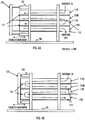
- Figure 4A depicts a scenario in which the actuating unit 120 is at a first position, which may be seen as one of the two extreme positions of the actuating unit 120.
- parts of the floors 208 of the even modules 110B, 110D i.e. modules 2, 4, 6, ... from the above
- the exit apertures 112 of these even modules 110B, 110D are opened from the other ends of these modules 110B, 110D.
- the material may drop from these modules 110B, 110D to the modules below 110C and to ambient, as shown in Figure 4A .
- the floors 208 of the odd modules 110A, 110C i.e. modules 1, 3, 5, ... from the above
- the exit apertures 112 of these modules 110A, 110C may be closed.
- FIG 4B depicts a scenario in which the actuating unit 120 is at a second position, which may be seen as the other of the two extreme positions of the actuating unit 120.
- the second position parts of the floors 208 of the odd modules 110A, 110C may be pushed out from one end of these modules 110A, 110C, as shown in Figure 4A .
- the exit apertures 112 of these odd modules 110A, 110C are opened from the other ends of these modules 110A, 110C.
- the material may drop from these modules 110A, 110C to the modules below 110B, 110D, as shown in Figure 4B .
- the floors 208 of the even modules 110B, 110D may be inside the modules 110B, 110D and the exit apertures 112 of these modules 110B, 110D may be closed.
- the movements of the odd and even modules 110 may be switched, depending on which end of the uppermost module the material is fed in to the apparatus. Further, in case several actuating units 120 are used for independently moving the floors 208 of different modules 110A-110D, then the synchronization between the movements or opening/closings of the exit apertures 112 of different modules is not needed.
- the movement of the floor 208 in each module 110 may provide for the opening and closing of the apertures. This may be beneficial in that the material better mixes in the apparatus 100 when the material is exposed to sudden drop from the upper module to the lower module. Further, the moving floor 208 may also contribute to the mixing of the material and to the movement of the material towards the exit apertures 112 in each module 110.
- each paddle 210 is pivotally fixed at one of its end to either of the non-moving sidewalls 200, 202 of the module 110 and the other end of the paddle 210 is configured to move freely according to (i.e. along) the movement of the floor 208 of the module 110, thereby causing the paddle 210 to rotate about the pivot 212. This may be because the free end of the paddle 210 is lying against the moving floor 208, and thereby moving as the floor 208 moves to the direction of the floor movement.
- each paddle 210 may be configured to rotate about the pivot 212 such that when the floor 208 moves in the movement direction of the material, the paddle 210 may be substantially parallel to the sidewall 200/202.
- substantially parallel may mean an orientation in which the tip of the paddle 210 points substantially to the direction of the exit aperture 112. That is, the paddle 210 does not block the material moving forwards along the floor 208.
- the paddle 210 may be substantially transversal to the sidewall 200/202.
- substantially transversal may mean an orientation in which the paddle 210 blocks the material moving backwards along the floor 208.
- Figure 5 depicts the operation of a given module 110C when looking from above.
- paddles 210 are present only on one sidewall 202 of the module 110C.
- Figure 5 depicts the operation of one module in different positions of the actuating unit 120, which moves the floor 208, and consequently the paddles 210.
- FIG. 5 shows the operation of the odd module 110C.
- the dotted box represents the movement of the floor 208 of the module.
- the module 110C for example, comprises material AA, A, B, C, D, and E. These may be seen as chunks/piles of material, although a continuous flow of material is more likely case in practise. However, for the sake of simplicity of the description, piles of material are used.
- material F is inputted to the module 110A. It may be seen that the floor 208 is at the second position and the exit aperture 112 at one end of the module 110C is open. As a result, the material AA located at that end of the module 110C is dropping out of the module 110C to the module 110D below.
- the paddles 210 are substantially transversal to the sidewall to which the paddles 210 are pivotally fixed. This may be because the floor 208 has moved backwards against the movement direction of the material and pulled the free ends of the paddles 210.
- the structure of the pivot 212 or the attachment mechanism may be arranged to limit the rotation of the paddle 210 so that the paddle 210 may not be allowed to rotate more than substantially 90 degrees.
- the rotation of the paddle 210 may be limited so that the paddle 210 may not point towards that end of the module 110C from which the material is fed in, but only to the end of the module 110C from which the material exits the module.
- the actuating unit 120 (and the floor 208) is at the first position.
- the floor 208 has moved forward in the movement direction of the material. Therefore, also the material piles A-F, lying on the floor 208, have moved forward a distance which roughly corresponds to the cylinder-stroke distance, as shown with dashed arrows.
- New material E may have come in to the module 110A.
- the paddles 210 are now oriented towards the exit aperture 112 (are substantially parallel to the sidewall 202). This may be because the moving floor 208 has pushed the free ends of the paddles 210.
- the paddles 210 do not block the material moving along with the moving floor 208.
- the exit aperture 112 may now be closed by the moving floor 208.
- the floor 208 has been again retracted to the second position.
- the free ends of the paddles 210 may again be pulled back so that the orientation of the paddles 210 is substantially transversal to the sidewall 202. This may be beneficial as then the paddles 210 may block the movement of the material backwards along the floor 208 moving backwards.
- the exit aperture 112 may now again be open and material A may drop to the module 110B below. In this manner the material may mix and move forwards in impulses in the odd modules 110A, 110C.
- the operation of the even modules 110B, 110D may be identical to the operation of the odd module 110A, 110C. However, it may be noted that in order for the movement direction of the material to be opposite in the odd and even modules, an even modules may be turned 180 degrees in horizontal plane when compared to an odd module. Also the floor 208 of an even module may have a cylinder-stroke distance offset with respect to the floor 208 of an odd module, as may be seen in Figures 4A and 4B .
- Each module 110 may have an identical operation principle and effect similar to the drying process of the material. Therefore, the more modules 110 there are, the more the apparatus 100 dries the material.
- the actuator unit may rotate the paddles 210 back-and-forth about the pivot 212 so as to impulsively move the material in the module forwards, i.e. towards the exit aperture 112.
- the rotation of the paddle 210 may be limited about the pivot 212, as explained above.
- the movement of the paddles 210 as shown with the dotted bi-directional arrows may move the material impulsively towards the exit aperture 112.
- the floor 208 may be static and the exit apertures 112 may be constantly open.
- the movement of the paddles 210 may be caused by an actuating unit applying an electric or hydraulic motor coupled to the paddles 210, for example.
- each module 110 comprises a plurality of rotating paddle wheels for moving the material.
- the paddle wheel may be, e.g., hanging from the roof of the module 110 or otherwise disposed in the module 110 so that the paddles 210 of the rotating paddle wheel may impulsively move the material on the floor 208 of the module 110.
- the actuator unit may be configured to rotate the paddle wheel.
- the floor 208 may be static and the exit apertures 112 may be constantly open.
- inner corners of the modules 110 are rounded so that the amount of material stuck at the inner corners is minimized.
- the uppermost module 110A is coupled to the material inlet 102 and the heat outlet 109, and the lowermost module 110D is coupled to the material outlet 104 and the heat inlet 108. This may provide for efficient drying/heating as the material needs to travel through the whole apparatus 100. It may be appreciated that at least the uppermost module 110A may be equipped with the roof. The roof may be integral part of the uppermost module or the roof may be detachably attached to the uppermost module 110A.
- At least one other module (such as module 110B, 110C) is additionally coupled to at least one of the following: a second heat inlet for inputting more heat to the apparatus 100, and a second heat outlet for enabling heat to exit the apparatus 100.
- a second heat inlet for inputting more heat to the apparatus 100
- a second heat outlet for enabling heat to exit the apparatus 100.
- these inlet(s) and outlet(s) may be opened/closed on the basis of detecting a need for more or less heat. The detection may be made on the basis of sensors indicating such need, or by monitoring the output material, for example.
- the level of drying by the apparatus 100 may be controlled in many ways, such as by adding or removing modules, or by controlling the temperature or amount of the input heat.
- adding a module the material needs to traverse a longer distance in the apparatus 110, thereby causing the output product to be drier.
- the output material may be moister.
- the dimensions of the modules 110 and/or the paddles 210 may be designed according to the to-be-dried material, for example. Such designing may benefit from empirical testing of which dimensions work best for which materials, for example.
- the increment of the drying capability by adding the module(s) may not affect the required area for the apparatus 100.
- the addition of the modules to the apparatus 100 only affects the height of the apparatus 100.
- the material does not pile up (does not pelletize).
- the speed of the impulses e.g. the speed of the cylinder strokes
- the length of the impulses e.g. the length of the cylinder strokes
- the modules 110 may be mutually interchangeable.
- different modules are releasably fixed on top of each other.
- Such fixing may be made with screws and bolts, or by quick clamping, for example.
- at least the lowermost module 110D may be somewhat different, or at least some modifications may be needed, so as to provide for the coupling of inlets of the heat.
- the modular structure of the apparatus 100 comprising a plurality of interchangeable modules 110 may provide ease of repair/maintenance because a damaged or otherwise mal-functioning module may be replaced with a new module without changing other parts of the apparatus 100.
- a damaged or otherwise mal-functioning module may be replaced with a new module without changing other parts of the apparatus 100.
- the module 110C is damaged.
- the user of the apparatus 100 may detach the modules 110A-110C from the supporting structure 106 (and from the actuating unit 120).
- the modules 110A-110C may then be lifted out of the apparatus 100 and the damaged module 110C may be replaced with a new module 110E.
- the modules 110A, 110B, 110E may be lifted back to the apparatus 100 and attached to the supporting structure 106 (and to the actuating unit 120).
- switching one or more of the modules 110 may be easy and fast.
- the cold replacement module 110E is disposed on the location of the damaged module 110C, so that the cold replacement module 110E heats up relatively fast. In another embodiment, the cold replacement module 110E is disposed as the uppermost module of the apparatus 100, so that the cold module 110E does not disturb the already heated lower portion of the apparatus 100.
- the module 110B may need to be turned 180 degrees in a horizontal plane so that movement of the paddles 210 is appropriate.
- the treatment of the material may be completely performed by applying only these modules 110A-110D. Therefore, in an embodiment, no other material treatment modules or elements are applied.
- the apparatus 100 may comprise at least one sensor for sensing at least one of the following: temperature of the material or the location in which the sensor is located, moisture content of the material, dry content of the material, particle size of the material, pressure of the location in which the sensor is located, flow of material.
- the location of the at least one sensor may be in at least one of the modules 110.
- the use of the sensor may be beneficial as then the user of the apparatus 100 obtains knowledge of how well the material has dried in a given location of the apparatus 100. In case it is detected that the material is already well dried in the middle parts of the apparatus 100, the amount or temperature of heat may be decreased or some of the modules 110 may be removed, for example.
- the pressure sensor and/or the temperature sensor may indicate a potential risk of an accident and the user may apply this knowledge in preventing the accident.
- the sensors may be wireless sensors transmitting the sensing results wirelessly to a user computer.
- the sensors may apply a thermometer or machine vision, for example.
- a method for drying material in a multi-module counterflow drying apparatus 100 comprising: feeding material to the upperpart of the apparatus 100, outputting material from the lower part of the apparatus 100, inputting heat to the apparatus 100 such that the heat traverses the apparatus 100 in the opposite direction than the material.
- a multi-module counterflow drying apparatus 100 for drying material comprising: a material input means 102 for inputting material to the upperpart of the apparatus, a material output means 104 for outputting dried material from the lower part of the apparatus, a heat input means 108 for inputting heat to the apparatus such that the heat traverses the apparatus in the opposite direction than the material, and a plurality of mutually interchangeable modules 110 stacked on top of each other, wherein the material is configured to move in the apparatus from one module to another such that the movement direction of the material in a given module is opposite to the movement direction of the material in a module above or below the given module, wherein each module comprises movable mixing means (e.g. the paddles 210) configured to discontinuously move the material forward in the module.
- movable mixing means e.g. the paddles 210) configured to discontinuously move the material forward in the module.
- the apparatus 100 may further comprise at least one processor and at least one memory including a computer program code, wherein the at least one memory and the computer program code are configured, with the at least one processor, to cause the apparatus 100 to perform in the described manner.
- the movement of the actuating unit 120 may be controlled by the processor or a circuitry of the processor.
- the memory may be implemented using any suitable data storage technology, such as semiconductor based memory devices, flash memory, magnetic memory devices and systems, optical memory devices and systems, fixed memory and removable memory.
- the apparatus 100 may further comprise communication interface comprising hardware and/or software for realizing communication connectivity according to one or more communication protocols.
- the communication interface may provide the apparatus 100 with communication capabilities for indicating the result of the sensors, amount of material passed through the apparatus 100, for example.
- the apparatus 100 may also comprise a user interface comprising, for example, at least one keypad, a microphone, a touch display, a display, a speaker, etc. The user interface may be used to control the apparatus 100 by the user.
- Some of the embodiments may be driven by a computer process defined by a computer program.
- the computer program may be in source code form, object code form, or in some intermediate form, and it may be stored in some sort of carrier, which may be any entity or device capable of carrying the program.
- the computer program may be stored on a computer program distribution medium readable by a computer or a processor.
- the computer program medium may be, for example but not limited to, a record medium, computer memory, read-only memory, electrical carrier signal, telecommunications signal, and software distribution package, for example. Coding of software for carrying out the embodiments as shown and described is well within the scope of a person of ordinary skill in the art.
Landscapes
- Engineering & Computer Science (AREA)
- Mechanical Engineering (AREA)
- General Engineering & Computer Science (AREA)
- Drying Of Solid Materials (AREA)
Claims (10)
- Appareil de séchage à contre-courant à plusieurs modules (100) pour sécher un matériau, l'appareil (100) comprenant :une entrée de matériau (102) pour introduire un matériau dans la partie supérieure de l'appareil ;une sortie de matériau (104) pour délivrer en sortie le matériau séché à partir de la partie inférieure de l'appareil ;une entrée de chaleur (108) pour introduire de la chaleur à l'appareil de sorte que la chaleur traverse l'appareil dans la direction opposée à celle du matériau ;des palettes mobiles (210) configurées pour déplacer de manière discontinue le matériau vers l'avant ; caractérisé parune pluralité de modules mutuellement interchangeables (110) empilés les uns sur les autres, où le matériau est configuré pour se déplacer dans l'appareil d'un module à un autre de sorte que la direction de déplacement du matériau dans un module donné soit opposée à la direction de déplacement du matériau dans un module au-dessus ou en dessous du module donné, où chaque module (110) comprend lesdites palettes mobiles (210), et où les palettes sont configurées pour déplacer de manière discontinue le matériau vers l'avant dans le module (110).
- Appareil de la revendication 1, dans lequel le module le plus haut (110A) est couplé à l'entrée de matériau (102), et le module le plus bas (110D) est couplé à la sortie de matériau (104) et à l'entrée de chaleur (108).
- Appareil de la revendication 2, dans lequel au moins un autre module (110B, 110C) est en plus couplé à au moins l'un des éléments suivants : une deuxième entrée de chaleur pour introduire plus de chaleur à l'appareil, une sortie de chaleur pour permettre à la chaleur de sortir de l'appareil.
- Appareil de l'une des revendications 1 à 3, dans lequel chaque palette (210) est fixée en pivotement au niveau de l'une de ses extrémités à l'une ou l'autre des parois latérales (200, 202) du module (110).
- Appareil de la revendication 4, dans lequel l'appareil comprend en outre :une unité d'actionnement (120) configurée pour faire tourner les palettes (210) en va-et-vient autour du pivot (212) de façon à déplacer le matériau par impulsions vers l'avant dans le module (110).
- Appareil de l'une des revendications 1 à 5, dans lequel l'appareil comprend en outre :une unité d'actionnement (120) configurée pour déplacer le plancher (208) de chaque module (110) en va-et-vient.
- Appareil de la revendication 6, dans lequel le mouvement de va-et-vient du plancher (208) dans un module donné (110) ouvre et ferme périodiquement une ouverture de sortie (112) du module (110) pour permettre au matériau en mouvement de tomber du module (110), où les planchers (208) de modules adjacents sont situés les uns par rapport aux autres de sorte que lorsque l'ouverture de sortie d'un module est ouverte, l'ouverture de sortie du module adjacent soit fermée.
- Appareil de l'une des revendications 6 et 7, dans lequel l'autre extrémité de chaque palette (210) est configurée pour se déplacer librement selon le déplacement du plancher (208) du module (110), amenant ainsi la palette (210) à tourner en va-et-vient autour du pivot (212).
- Appareil de la revendication 8, dans lequel chaque palette (210) est configurée pour tourner autour du pivot (212) de sorte que :lorsque le plancher (208) se déplace dans la direction de déplacement du matériau, la palette (210) soit essentiellement parallèle à la paroi latérale (200, 202), etlorsque le plancher (208) se déplace contre la direction de déplacement du matériau, la palette (210) soit essentiellement transversale à la paroi latérale (200, 202).
- Procédé de séchage de matériau dans un appareil de séchage à contre-courant à plusieurs modules (100), le procédé comprenant le fait :d'alimenter en matériau la partie supérieure de l'appareil (100) ;de délivrer en sortie le matériau à partir de la partie inférieure de l'appareil (100) ;d'introduire de la chaleur à l'appareil (100) de sorte que la chaleur traverse l'appareil (100) dans la direction opposée à celle du matériau,où l'appareil (100) comprend des palettes mobiles (210) configurées pour déplacer de manière discontinue le matériau vers l'avant, caractérisé en ce que l'appareil (100) comprend en outre :une pluralité de modules mutuellement interchangeables (110) empilés les uns sur les autres, où le matériau est configuré pour se déplacer dans l'appareil d'un module à un autre de sorte que la direction de déplacement du matériau dans un module donné soit opposée à la direction de déplacement du matériau dans un module au-dessus ou en dessous du module donné, où chaque module (110) comprend lesdites palettes mobiles (210) et où les palettes (210) sont configurées pour déplacer de manière discontinue le matériau vers l'avant dans le module (110).
Applications Claiming Priority (1)
| Application Number | Priority Date | Filing Date | Title |
|---|---|---|---|
| FI20145343A FI126756B (en) | 2014-04-10 | 2014-04-10 | Apparatus and method for drying material |
Publications (2)
| Publication Number | Publication Date |
|---|---|
| EP2937654A1 EP2937654A1 (fr) | 2015-10-28 |
| EP2937654B1 true EP2937654B1 (fr) | 2016-12-28 |
Family
ID=52814855
Family Applications (1)
| Application Number | Title | Priority Date | Filing Date |
|---|---|---|---|
| EP15162439.2A Active EP2937654B1 (fr) | 2014-04-10 | 2015-04-02 | Séchoir à modules multiples avec pagaies |
Country Status (4)
| Country | Link |
|---|---|
| US (1) | US10006710B2 (fr) |
| EP (1) | EP2937654B1 (fr) |
| CA (1) | CA2887183C (fr) |
| FI (1) | FI126756B (fr) |
Families Citing this family (4)
| Publication number | Priority date | Publication date | Assignee | Title |
|---|---|---|---|---|
| DE102018133070B4 (de) * | 2018-12-20 | 2021-08-05 | i +M GmbH & Co. KG Innovation und Management | Vorrichtung zum Trocknen von Klärschlamm |
| CN112050610B (zh) * | 2020-09-14 | 2021-12-14 | 青海益洁生物工程有限公司 | 一种全自动烘干设备 |
| CN112082376A (zh) * | 2020-09-14 | 2020-12-15 | 徐丽侠 | 一种物料摊匀装置 |
| CN113280610B (zh) * | 2021-05-31 | 2022-06-07 | 安徽华谷机械科技有限公司 | 一种梯度脱水的粮食烘干机 |
Family Cites Families (7)
| Publication number | Priority date | Publication date | Assignee | Title |
|---|---|---|---|---|
| GB139278A (en) | 1919-02-12 | 1920-03-04 | Samuel Charteris Wilson | Improvements in apparatus or means for drying wool |
| US2050477A (en) * | 1935-03-15 | 1936-08-11 | Weisselberg Arnold | Method and apparatus for spreading divided material for treatment or other purposes |
| US3060589A (en) | 1958-03-25 | 1962-10-30 | Svenska Flaektfabriken Ab | Drying granular materials |
| LT4610B (lt) | 1997-11-03 | 2000-01-25 | Lietuvos Žemės Ūkio Inžinerijos Institutas | Konvejerinė džiovykla |
| DE10310258A1 (de) | 2003-03-05 | 2004-09-16 | Erwin Keller | Trocknungsvorrichtung, insbesondere für Klärschlamm |
| KR20090132156A (ko) | 2008-06-20 | 2009-12-30 | 김영애 | 건조장치 |
| JP5423711B2 (ja) | 2011-03-30 | 2014-02-19 | 住友大阪セメント株式会社 | 多段型有機物乾燥システム |
-
2014
- 2014-04-10 FI FI20145343A patent/FI126756B/en active IP Right Grant
-
2015
- 2015-04-02 US US14/677,290 patent/US10006710B2/en active Active
- 2015-04-02 EP EP15162439.2A patent/EP2937654B1/fr active Active
- 2015-04-08 CA CA2887183A patent/CA2887183C/fr active Active
Non-Patent Citations (1)
| Title |
|---|
| None * |
Also Published As
| Publication number | Publication date |
|---|---|
| CA2887183A1 (fr) | 2015-10-10 |
| US10006710B2 (en) | 2018-06-26 |
| US20150292800A1 (en) | 2015-10-15 |
| CA2887183C (fr) | 2022-08-16 |
| EP2937654A1 (fr) | 2015-10-28 |
| FI20145343A7 (fi) | 2015-10-11 |
| FI126756B (en) | 2017-05-15 |
Similar Documents
| Publication | Publication Date | Title |
|---|---|---|
| EP2937654B1 (fr) | Séchoir à modules multiples avec pagaies | |
| JP6233955B2 (ja) | 乾燥装置 | |
| PT1601744E (pt) | Aparelho e método de gaseificação | |
| KR20090132156A (ko) | 건조장치 | |
| CN102305523A (zh) | 一种回转滚筒干燥机 | |
| CN102642642A (zh) | 一种热收缩机 | |
| US20160345387A1 (en) | System and method for processing solids and liquids | |
| JP2006349316A (ja) | 乾燥装置 | |
| CN102514369A (zh) | 一种印刷机烘干装置 | |
| CN105605905A (zh) | 一种蚯蚓干燥设备 | |
| CN106440710A (zh) | 集成式实验室全自动制粒干燥整粒混合一体机 | |
| CN202709641U (zh) | 一种振动流化床干燥机 | |
| CN206310861U (zh) | 一种旋转干燥机热能利用装置 | |
| CN207192083U (zh) | 一种农产品喷码机和扫码机的可变位置下料口 | |
| SE536195C2 (sv) | Tillförselanordning för förbränningskammare och metod därför | |
| CN206856260U (zh) | 一种基于绿色环保印刷工艺技术的印刷烘干装置 | |
| CN102200381A (zh) | 一种高效篦式烘干机 | |
| ES3041070T3 (en) | Control of an asphalt mixing plant | |
| CA2991070A1 (fr) | Agencement structural pour usine d'asphalte gravimetrique | |
| CN105371639A (zh) | 氟化铝快速干燥装置及工艺 | |
| CN102679691A (zh) | 具有温度控制功能的沸腾干燥机 | |
| CN106123538A (zh) | 一种工件烘干装置 | |
| CN106931745A (zh) | 一种复合肥烘干装置 | |
| CN202083187U (zh) | 回转滚筒干燥机 | |
| CN104171048A (zh) | 茶叶烘干机 |
Legal Events
| Date | Code | Title | Description |
|---|---|---|---|
| PUAI | Public reference made under article 153(3) epc to a published international application that has entered the european phase |
Free format text: ORIGINAL CODE: 0009012 |
|
| AK | Designated contracting states |
Kind code of ref document: A1 Designated state(s): AL AT BE BG CH CY CZ DE DK EE ES FI FR GB GR HR HU IE IS IT LI LT LU LV MC MK MT NL NO PL PT RO RS SE SI SK SM TR |
|
| AX | Request for extension of the european patent |
Extension state: BA ME |
|
| 17P | Request for examination filed |
Effective date: 20160425 |
|
| RBV | Designated contracting states (corrected) |
Designated state(s): AL AT BE BG CH CY CZ DE DK EE ES FI FR GB GR HR HU IE IS IT LI LT LU LV MC MK MT NL NO PL PT RO RS SE SI SK SM TR |
|
| GRAP | Despatch of communication of intention to grant a patent |
Free format text: ORIGINAL CODE: EPIDOSNIGR1 |
|
| INTG | Intention to grant announced |
Effective date: 20160720 |
|
| GRAS | Grant fee paid |
Free format text: ORIGINAL CODE: EPIDOSNIGR3 |
|
| GRAA | (expected) grant |
Free format text: ORIGINAL CODE: 0009210 |
|
| AK | Designated contracting states |
Kind code of ref document: B1 Designated state(s): AL AT BE BG CH CY CZ DE DK EE ES FI FR GB GR HR HU IE IS IT LI LT LU LV MC MK MT NL NO PL PT RO RS SE SI SK SM TR |
|
| REG | Reference to a national code |
Ref country code: GB Ref legal event code: FG4D |
|
| REG | Reference to a national code |
Ref country code: CH Ref legal event code: EP |
|
| REG | Reference to a national code |
Ref country code: AT Ref legal event code: REF Ref document number: 857661 Country of ref document: AT Kind code of ref document: T Effective date: 20170115 |
|
| REG | Reference to a national code |
Ref country code: IE Ref legal event code: FG4D |
|
| REG | Reference to a national code |
Ref country code: DE Ref legal event code: R096 Ref document number: 602015001098 Country of ref document: DE |
|
| PG25 | Lapsed in a contracting state [announced via postgrant information from national office to epo] |
Ref country code: LV Free format text: LAPSE BECAUSE OF FAILURE TO SUBMIT A TRANSLATION OF THE DESCRIPTION OR TO PAY THE FEE WITHIN THE PRESCRIBED TIME-LIMIT Effective date: 20161228 |
|
| REG | Reference to a national code |
Ref country code: SE Ref legal event code: TRGR |
|
| REG | Reference to a national code |
Ref country code: NL Ref legal event code: FP |
|
| REG | Reference to a national code |
Ref country code: FR Ref legal event code: PLFP Year of fee payment: 3 |
|
| REG | Reference to a national code |
Ref country code: LT Ref legal event code: MG4D |
|
| PG25 | Lapsed in a contracting state [announced via postgrant information from national office to epo] |
Ref country code: LT Free format text: LAPSE BECAUSE OF FAILURE TO SUBMIT A TRANSLATION OF THE DESCRIPTION OR TO PAY THE FEE WITHIN THE PRESCRIBED TIME-LIMIT Effective date: 20161228 Ref country code: GR Free format text: LAPSE BECAUSE OF FAILURE TO SUBMIT A TRANSLATION OF THE DESCRIPTION OR TO PAY THE FEE WITHIN THE PRESCRIBED TIME-LIMIT Effective date: 20170329 Ref country code: NO Free format text: LAPSE BECAUSE OF FAILURE TO SUBMIT A TRANSLATION OF THE DESCRIPTION OR TO PAY THE FEE WITHIN THE PRESCRIBED TIME-LIMIT Effective date: 20170328 |
|
| REG | Reference to a national code |
Ref country code: AT Ref legal event code: MK05 Ref document number: 857661 Country of ref document: AT Kind code of ref document: T Effective date: 20161228 |
|
| PG25 | Lapsed in a contracting state [announced via postgrant information from national office to epo] |
Ref country code: HR Free format text: LAPSE BECAUSE OF FAILURE TO SUBMIT A TRANSLATION OF THE DESCRIPTION OR TO PAY THE FEE WITHIN THE PRESCRIBED TIME-LIMIT Effective date: 20161228 Ref country code: FI Free format text: LAPSE BECAUSE OF FAILURE TO SUBMIT A TRANSLATION OF THE DESCRIPTION OR TO PAY THE FEE WITHIN THE PRESCRIBED TIME-LIMIT Effective date: 20161228 Ref country code: RS Free format text: LAPSE BECAUSE OF FAILURE TO SUBMIT A TRANSLATION OF THE DESCRIPTION OR TO PAY THE FEE WITHIN THE PRESCRIBED TIME-LIMIT Effective date: 20161228 |
|
| PG25 | Lapsed in a contracting state [announced via postgrant information from national office to epo] |
Ref country code: RO Free format text: LAPSE BECAUSE OF FAILURE TO SUBMIT A TRANSLATION OF THE DESCRIPTION OR TO PAY THE FEE WITHIN THE PRESCRIBED TIME-LIMIT Effective date: 20161228 Ref country code: SK Free format text: LAPSE BECAUSE OF FAILURE TO SUBMIT A TRANSLATION OF THE DESCRIPTION OR TO PAY THE FEE WITHIN THE PRESCRIBED TIME-LIMIT Effective date: 20161228 Ref country code: EE Free format text: LAPSE BECAUSE OF FAILURE TO SUBMIT A TRANSLATION OF THE DESCRIPTION OR TO PAY THE FEE WITHIN THE PRESCRIBED TIME-LIMIT Effective date: 20161228 Ref country code: IS Free format text: LAPSE BECAUSE OF FAILURE TO SUBMIT A TRANSLATION OF THE DESCRIPTION OR TO PAY THE FEE WITHIN THE PRESCRIBED TIME-LIMIT Effective date: 20170428 Ref country code: CZ Free format text: LAPSE BECAUSE OF FAILURE TO SUBMIT A TRANSLATION OF THE DESCRIPTION OR TO PAY THE FEE WITHIN THE PRESCRIBED TIME-LIMIT Effective date: 20161228 |
|
| PG25 | Lapsed in a contracting state [announced via postgrant information from national office to epo] |
Ref country code: SM Free format text: LAPSE BECAUSE OF FAILURE TO SUBMIT A TRANSLATION OF THE DESCRIPTION OR TO PAY THE FEE WITHIN THE PRESCRIBED TIME-LIMIT Effective date: 20161228 Ref country code: PT Free format text: LAPSE BECAUSE OF FAILURE TO SUBMIT A TRANSLATION OF THE DESCRIPTION OR TO PAY THE FEE WITHIN THE PRESCRIBED TIME-LIMIT Effective date: 20170428 Ref country code: IT Free format text: LAPSE BECAUSE OF FAILURE TO SUBMIT A TRANSLATION OF THE DESCRIPTION OR TO PAY THE FEE WITHIN THE PRESCRIBED TIME-LIMIT Effective date: 20161228 Ref country code: ES Free format text: LAPSE BECAUSE OF FAILURE TO SUBMIT A TRANSLATION OF THE DESCRIPTION OR TO PAY THE FEE WITHIN THE PRESCRIBED TIME-LIMIT Effective date: 20161228 Ref country code: BE Free format text: LAPSE BECAUSE OF FAILURE TO SUBMIT A TRANSLATION OF THE DESCRIPTION OR TO PAY THE FEE WITHIN THE PRESCRIBED TIME-LIMIT Effective date: 20161228 Ref country code: AT Free format text: LAPSE BECAUSE OF FAILURE TO SUBMIT A TRANSLATION OF THE DESCRIPTION OR TO PAY THE FEE WITHIN THE PRESCRIBED TIME-LIMIT Effective date: 20161228 Ref country code: PL Free format text: LAPSE BECAUSE OF FAILURE TO SUBMIT A TRANSLATION OF THE DESCRIPTION OR TO PAY THE FEE WITHIN THE PRESCRIBED TIME-LIMIT Effective date: 20161228 Ref country code: BG Free format text: LAPSE BECAUSE OF FAILURE TO SUBMIT A TRANSLATION OF THE DESCRIPTION OR TO PAY THE FEE WITHIN THE PRESCRIBED TIME-LIMIT Effective date: 20170328 |
|
| REG | Reference to a national code |
Ref country code: DE Ref legal event code: R097 Ref document number: 602015001098 Country of ref document: DE |
|
| PLBE | No opposition filed within time limit |
Free format text: ORIGINAL CODE: 0009261 |
|
| STAA | Information on the status of an ep patent application or granted ep patent |
Free format text: STATUS: NO OPPOSITION FILED WITHIN TIME LIMIT |
|
| PG25 | Lapsed in a contracting state [announced via postgrant information from national office to epo] |
Ref country code: DK Free format text: LAPSE BECAUSE OF FAILURE TO SUBMIT A TRANSLATION OF THE DESCRIPTION OR TO PAY THE FEE WITHIN THE PRESCRIBED TIME-LIMIT Effective date: 20161228 |
|
| 26N | No opposition filed |
Effective date: 20170929 |
|
| REG | Reference to a national code |
Ref country code: IE Ref legal event code: MM4A |
|
| PG25 | Lapsed in a contracting state [announced via postgrant information from national office to epo] |
Ref country code: MC Free format text: LAPSE BECAUSE OF FAILURE TO SUBMIT A TRANSLATION OF THE DESCRIPTION OR TO PAY THE FEE WITHIN THE PRESCRIBED TIME-LIMIT Effective date: 20161228 |
|
| PG25 | Lapsed in a contracting state [announced via postgrant information from national office to epo] |
Ref country code: LU Free format text: LAPSE BECAUSE OF NON-PAYMENT OF DUE FEES Effective date: 20170402 Ref country code: SI Free format text: LAPSE BECAUSE OF FAILURE TO SUBMIT A TRANSLATION OF THE DESCRIPTION OR TO PAY THE FEE WITHIN THE PRESCRIBED TIME-LIMIT Effective date: 20161228 |
|
| REG | Reference to a national code |
Ref country code: FR Ref legal event code: PLFP Year of fee payment: 4 |
|
| PG25 | Lapsed in a contracting state [announced via postgrant information from national office to epo] |
Ref country code: IE Free format text: LAPSE BECAUSE OF NON-PAYMENT OF DUE FEES Effective date: 20170402 |
|
| PG25 | Lapsed in a contracting state [announced via postgrant information from national office to epo] |
Ref country code: MT Free format text: LAPSE BECAUSE OF NON-PAYMENT OF DUE FEES Effective date: 20170402 |
|
| REG | Reference to a national code |
Ref country code: CH Ref legal event code: PL |
|
| PG25 | Lapsed in a contracting state [announced via postgrant information from national office to epo] |
Ref country code: LI Free format text: LAPSE BECAUSE OF NON-PAYMENT OF DUE FEES Effective date: 20180430 Ref country code: CH Free format text: LAPSE BECAUSE OF NON-PAYMENT OF DUE FEES Effective date: 20180430 |
|
| PG25 | Lapsed in a contracting state [announced via postgrant information from national office to epo] |
Ref country code: HU Free format text: LAPSE BECAUSE OF FAILURE TO SUBMIT A TRANSLATION OF THE DESCRIPTION OR TO PAY THE FEE WITHIN THE PRESCRIBED TIME-LIMIT; INVALID AB INITIO Effective date: 20150402 |
|
| PG25 | Lapsed in a contracting state [announced via postgrant information from national office to epo] |
Ref country code: CY Free format text: LAPSE BECAUSE OF FAILURE TO SUBMIT A TRANSLATION OF THE DESCRIPTION OR TO PAY THE FEE WITHIN THE PRESCRIBED TIME-LIMIT Effective date: 20161228 |
|
| PG25 | Lapsed in a contracting state [announced via postgrant information from national office to epo] |
Ref country code: MK Free format text: LAPSE BECAUSE OF FAILURE TO SUBMIT A TRANSLATION OF THE DESCRIPTION OR TO PAY THE FEE WITHIN THE PRESCRIBED TIME-LIMIT Effective date: 20161228 |
|
| PG25 | Lapsed in a contracting state [announced via postgrant information from national office to epo] |
Ref country code: TR Free format text: LAPSE BECAUSE OF FAILURE TO SUBMIT A TRANSLATION OF THE DESCRIPTION OR TO PAY THE FEE WITHIN THE PRESCRIBED TIME-LIMIT Effective date: 20161228 |
|
| PG25 | Lapsed in a contracting state [announced via postgrant information from national office to epo] |
Ref country code: AL Free format text: LAPSE BECAUSE OF FAILURE TO SUBMIT A TRANSLATION OF THE DESCRIPTION OR TO PAY THE FEE WITHIN THE PRESCRIBED TIME-LIMIT Effective date: 20161228 |
|
| PGFP | Annual fee paid to national office [announced via postgrant information from national office to epo] |
Ref country code: NL Payment date: 20251016 Year of fee payment: 11 |
|
| PGFP | Annual fee paid to national office [announced via postgrant information from national office to epo] |
Ref country code: DE Payment date: 20251017 Year of fee payment: 11 |
|
| PGFP | Annual fee paid to national office [announced via postgrant information from national office to epo] |
Ref country code: GB Payment date: 20251016 Year of fee payment: 11 |
|
| PGFP | Annual fee paid to national office [announced via postgrant information from national office to epo] |
Ref country code: FR Payment date: 20251016 Year of fee payment: 11 |
|
| PGFP | Annual fee paid to national office [announced via postgrant information from national office to epo] |
Ref country code: SE Payment date: 20251016 Year of fee payment: 11 |