EP2937672A1 - Codeur absolu, procédé de traitement, programme, appareil d'entraînement et machine industrielle - Google Patents
Codeur absolu, procédé de traitement, programme, appareil d'entraînement et machine industrielle Download PDFInfo
- Publication number
- EP2937672A1 EP2937672A1 EP15163049.8A EP15163049A EP2937672A1 EP 2937672 A1 EP2937672 A1 EP 2937672A1 EP 15163049 A EP15163049 A EP 15163049A EP 2937672 A1 EP2937672 A1 EP 2937672A1
- Authority
- EP
- European Patent Office
- Prior art keywords
- code sequence
- signal
- code
- candidate group
- absolute
- Prior art date
- Legal status (The legal status is an assumption and is not a legal conclusion. Google has not performed a legal analysis and makes no representation as to the accuracy of the status listed.)
- Withdrawn
Links
- 238000003672 processing method Methods 0.000 title claims description 7
- 238000000034 method Methods 0.000 claims description 36
- 230000001133 acceleration Effects 0.000 claims description 3
- 230000014509 gene expression Effects 0.000 description 17
- 239000011295 pitch Substances 0.000 description 13
- 230000006870 function Effects 0.000 description 11
- 238000002310 reflectometry Methods 0.000 description 11
- 238000003860 storage Methods 0.000 description 7
- 239000000758 substrate Substances 0.000 description 7
- 238000001514 detection method Methods 0.000 description 6
- 239000006059 cover glass Substances 0.000 description 3
- 230000003287 optical effect Effects 0.000 description 3
- 238000006243 chemical reaction Methods 0.000 description 2
- 238000009826 distribution Methods 0.000 description 2
- 239000000428 dust Substances 0.000 description 2
- 230000000694 effects Effects 0.000 description 2
- 238000001459 lithography Methods 0.000 description 2
- 238000012935 Averaging Methods 0.000 description 1
- 238000003646 Spearman's rank correlation coefficient Methods 0.000 description 1
- 230000005856 abnormality Effects 0.000 description 1
- 230000001174 ascending effect Effects 0.000 description 1
- 230000009286 beneficial effect Effects 0.000 description 1
- 230000003247 decreasing effect Effects 0.000 description 1
- 238000010894 electron beam technology Methods 0.000 description 1
- 239000000284 extract Substances 0.000 description 1
- 238000003754 machining Methods 0.000 description 1
- 238000004519 manufacturing process Methods 0.000 description 1
- 239000000463 material Substances 0.000 description 1
- 238000000465 moulding Methods 0.000 description 1
- 238000001579 optical reflectometry Methods 0.000 description 1
- 239000002245 particle Substances 0.000 description 1
- 230000000737 periodic effect Effects 0.000 description 1
- 230000005855 radiation Effects 0.000 description 1
- 230000003252 repetitive effect Effects 0.000 description 1
- 230000035945 sensitivity Effects 0.000 description 1
Images





Classifications
-
- G—PHYSICS
- G01—MEASURING; TESTING
- G01D—MEASURING NOT SPECIALLY ADAPTED FOR A SPECIFIC VARIABLE; ARRANGEMENTS FOR MEASURING TWO OR MORE VARIABLES NOT COVERED IN A SINGLE OTHER SUBCLASS; TARIFF METERING APPARATUS; MEASURING OR TESTING NOT OTHERWISE PROVIDED FOR
- G01D5/00—Mechanical means for transferring the output of a sensing member; Means for converting the output of a sensing member to another variable where the form or nature of the sensing member does not constrain the means for converting; Transducers not specially adapted for a specific variable
- G01D5/26—Mechanical means for transferring the output of a sensing member; Means for converting the output of a sensing member to another variable where the form or nature of the sensing member does not constrain the means for converting; Transducers not specially adapted for a specific variable characterised by optical transfer means, i.e. using infrared, visible, or ultraviolet light
- G01D5/32—Mechanical means for transferring the output of a sensing member; Means for converting the output of a sensing member to another variable where the form or nature of the sensing member does not constrain the means for converting; Transducers not specially adapted for a specific variable characterised by optical transfer means, i.e. using infrared, visible, or ultraviolet light with attenuation or whole or partial obturation of beams of light
- G01D5/34—Mechanical means for transferring the output of a sensing member; Means for converting the output of a sensing member to another variable where the form or nature of the sensing member does not constrain the means for converting; Transducers not specially adapted for a specific variable characterised by optical transfer means, i.e. using infrared, visible, or ultraviolet light with attenuation or whole or partial obturation of beams of light the beams of light being detected by photocells
- G01D5/347—Mechanical means for transferring the output of a sensing member; Means for converting the output of a sensing member to another variable where the form or nature of the sensing member does not constrain the means for converting; Transducers not specially adapted for a specific variable characterised by optical transfer means, i.e. using infrared, visible, or ultraviolet light with attenuation or whole or partial obturation of beams of light the beams of light being detected by photocells using displacement encoding scales
- G01D5/34776—Absolute encoders with analogue or digital scales
- G01D5/34792—Absolute encoders with analogue or digital scales with only digital scales or both digital and incremental scales
-
- G—PHYSICS
- G01—MEASURING; TESTING
- G01D—MEASURING NOT SPECIALLY ADAPTED FOR A SPECIFIC VARIABLE; ARRANGEMENTS FOR MEASURING TWO OR MORE VARIABLES NOT COVERED IN A SINGLE OTHER SUBCLASS; TARIFF METERING APPARATUS; MEASURING OR TESTING NOT OTHERWISE PROVIDED FOR
- G01D5/00—Mechanical means for transferring the output of a sensing member; Means for converting the output of a sensing member to another variable where the form or nature of the sensing member does not constrain the means for converting; Transducers not specially adapted for a specific variable
- G01D5/12—Mechanical means for transferring the output of a sensing member; Means for converting the output of a sensing member to another variable where the form or nature of the sensing member does not constrain the means for converting; Transducers not specially adapted for a specific variable using electric or magnetic means
- G01D5/244—Mechanical means for transferring the output of a sensing member; Means for converting the output of a sensing member to another variable where the form or nature of the sensing member does not constrain the means for converting; Transducers not specially adapted for a specific variable using electric or magnetic means influencing characteristics of pulses or pulse trains; generating pulses or pulse trains
- G01D5/24457—Failure detection
- G01D5/24461—Failure detection by redundancy or plausibility
-
- G—PHYSICS
- G01—MEASURING; TESTING
- G01D—MEASURING NOT SPECIALLY ADAPTED FOR A SPECIFIC VARIABLE; ARRANGEMENTS FOR MEASURING TWO OR MORE VARIABLES NOT COVERED IN A SINGLE OTHER SUBCLASS; TARIFF METERING APPARATUS; MEASURING OR TESTING NOT OTHERWISE PROVIDED FOR
- G01D5/00—Mechanical means for transferring the output of a sensing member; Means for converting the output of a sensing member to another variable where the form or nature of the sensing member does not constrain the means for converting; Transducers not specially adapted for a specific variable
- G01D5/12—Mechanical means for transferring the output of a sensing member; Means for converting the output of a sensing member to another variable where the form or nature of the sensing member does not constrain the means for converting; Transducers not specially adapted for a specific variable using electric or magnetic means
- G01D5/244—Mechanical means for transferring the output of a sensing member; Means for converting the output of a sensing member to another variable where the form or nature of the sensing member does not constrain the means for converting; Transducers not specially adapted for a specific variable using electric or magnetic means influencing characteristics of pulses or pulse trains; generating pulses or pulse trains
- G01D5/24471—Error correction
- G01D5/24495—Error correction using previous values
-
- G—PHYSICS
- G01—MEASURING; TESTING
- G01D—MEASURING NOT SPECIALLY ADAPTED FOR A SPECIFIC VARIABLE; ARRANGEMENTS FOR MEASURING TWO OR MORE VARIABLES NOT COVERED IN A SINGLE OTHER SUBCLASS; TARIFF METERING APPARATUS; MEASURING OR TESTING NOT OTHERWISE PROVIDED FOR
- G01D5/00—Mechanical means for transferring the output of a sensing member; Means for converting the output of a sensing member to another variable where the form or nature of the sensing member does not constrain the means for converting; Transducers not specially adapted for a specific variable
- G01D5/12—Mechanical means for transferring the output of a sensing member; Means for converting the output of a sensing member to another variable where the form or nature of the sensing member does not constrain the means for converting; Transducers not specially adapted for a specific variable using electric or magnetic means
- G01D5/244—Mechanical means for transferring the output of a sensing member; Means for converting the output of a sensing member to another variable where the form or nature of the sensing member does not constrain the means for converting; Transducers not specially adapted for a specific variable using electric or magnetic means influencing characteristics of pulses or pulse trains; generating pulses or pulse trains
- G01D5/249—Mechanical means for transferring the output of a sensing member; Means for converting the output of a sensing member to another variable where the form or nature of the sensing member does not constrain the means for converting; Transducers not specially adapted for a specific variable using electric or magnetic means influencing characteristics of pulses or pulse trains; generating pulses or pulse trains using pulse code
- G01D5/2492—Pulse stream
- G01D5/2495—Pseudo-random code
-
- G—PHYSICS
- G01—MEASURING; TESTING
- G01D—MEASURING NOT SPECIALLY ADAPTED FOR A SPECIFIC VARIABLE; ARRANGEMENTS FOR MEASURING TWO OR MORE VARIABLES NOT COVERED IN A SINGLE OTHER SUBCLASS; TARIFF METERING APPARATUS; MEASURING OR TESTING NOT OTHERWISE PROVIDED FOR
- G01D5/00—Mechanical means for transferring the output of a sensing member; Means for converting the output of a sensing member to another variable where the form or nature of the sensing member does not constrain the means for converting; Transducers not specially adapted for a specific variable
- G01D5/26—Mechanical means for transferring the output of a sensing member; Means for converting the output of a sensing member to another variable where the form or nature of the sensing member does not constrain the means for converting; Transducers not specially adapted for a specific variable characterised by optical transfer means, i.e. using infrared, visible, or ultraviolet light
- G01D5/32—Mechanical means for transferring the output of a sensing member; Means for converting the output of a sensing member to another variable where the form or nature of the sensing member does not constrain the means for converting; Transducers not specially adapted for a specific variable characterised by optical transfer means, i.e. using infrared, visible, or ultraviolet light with attenuation or whole or partial obturation of beams of light
- G01D5/34—Mechanical means for transferring the output of a sensing member; Means for converting the output of a sensing member to another variable where the form or nature of the sensing member does not constrain the means for converting; Transducers not specially adapted for a specific variable characterised by optical transfer means, i.e. using infrared, visible, or ultraviolet light with attenuation or whole or partial obturation of beams of light the beams of light being detected by photocells
- G01D5/347—Mechanical means for transferring the output of a sensing member; Means for converting the output of a sensing member to another variable where the form or nature of the sensing member does not constrain the means for converting; Transducers not specially adapted for a specific variable characterised by optical transfer means, i.e. using infrared, visible, or ultraviolet light with attenuation or whole or partial obturation of beams of light the beams of light being detected by photocells using displacement encoding scales
- G01D5/34707—Scales; Discs, e.g. fixation, fabrication, compensation
- G01D5/34715—Scale reading or illumination devices
-
- G—PHYSICS
- G01—MEASURING; TESTING
- G01D—MEASURING NOT SPECIALLY ADAPTED FOR A SPECIFIC VARIABLE; ARRANGEMENTS FOR MEASURING TWO OR MORE VARIABLES NOT COVERED IN A SINGLE OTHER SUBCLASS; TARIFF METERING APPARATUS; MEASURING OR TESTING NOT OTHERWISE PROVIDED FOR
- G01D5/00—Mechanical means for transferring the output of a sensing member; Means for converting the output of a sensing member to another variable where the form or nature of the sensing member does not constrain the means for converting; Transducers not specially adapted for a specific variable
- G01D5/26—Mechanical means for transferring the output of a sensing member; Means for converting the output of a sensing member to another variable where the form or nature of the sensing member does not constrain the means for converting; Transducers not specially adapted for a specific variable characterised by optical transfer means, i.e. using infrared, visible, or ultraviolet light
- G01D5/32—Mechanical means for transferring the output of a sensing member; Means for converting the output of a sensing member to another variable where the form or nature of the sensing member does not constrain the means for converting; Transducers not specially adapted for a specific variable characterised by optical transfer means, i.e. using infrared, visible, or ultraviolet light with attenuation or whole or partial obturation of beams of light
- G01D5/34—Mechanical means for transferring the output of a sensing member; Means for converting the output of a sensing member to another variable where the form or nature of the sensing member does not constrain the means for converting; Transducers not specially adapted for a specific variable characterised by optical transfer means, i.e. using infrared, visible, or ultraviolet light with attenuation or whole or partial obturation of beams of light the beams of light being detected by photocells
- G01D5/347—Mechanical means for transferring the output of a sensing member; Means for converting the output of a sensing member to another variable where the form or nature of the sensing member does not constrain the means for converting; Transducers not specially adapted for a specific variable characterised by optical transfer means, i.e. using infrared, visible, or ultraviolet light with attenuation or whole or partial obturation of beams of light the beams of light being detected by photocells using displacement encoding scales
- G01D5/34776—Absolute encoders with analogue or digital scales
-
- G—PHYSICS
- G05—CONTROLLING; REGULATING
- G05D—SYSTEMS FOR CONTROLLING OR REGULATING NON-ELECTRIC VARIABLES
- G05D3/00—Control of position or direction
- G05D3/12—Control of position or direction using feedback
- G05D3/20—Control of position or direction using feedback using a digital comparing device
-
- G—PHYSICS
- G01—MEASURING; TESTING
- G01D—MEASURING NOT SPECIALLY ADAPTED FOR A SPECIFIC VARIABLE; ARRANGEMENTS FOR MEASURING TWO OR MORE VARIABLES NOT COVERED IN A SINGLE OTHER SUBCLASS; TARIFF METERING APPARATUS; MEASURING OR TESTING NOT OTHERWISE PROVIDED FOR
- G01D5/00—Mechanical means for transferring the output of a sensing member; Means for converting the output of a sensing member to another variable where the form or nature of the sensing member does not constrain the means for converting; Transducers not specially adapted for a specific variable
- G01D5/12—Mechanical means for transferring the output of a sensing member; Means for converting the output of a sensing member to another variable where the form or nature of the sensing member does not constrain the means for converting; Transducers not specially adapted for a specific variable using electric or magnetic means
- G01D5/244—Mechanical means for transferring the output of a sensing member; Means for converting the output of a sensing member to another variable where the form or nature of the sensing member does not constrain the means for converting; Transducers not specially adapted for a specific variable using electric or magnetic means influencing characteristics of pulses or pulse trains; generating pulses or pulse trains
- G01D5/245—Mechanical means for transferring the output of a sensing member; Means for converting the output of a sensing member to another variable where the form or nature of the sensing member does not constrain the means for converting; Transducers not specially adapted for a specific variable using electric or magnetic means influencing characteristics of pulses or pulse trains; generating pulses or pulse trains using a variable number of pulses in a train
- G01D5/2454—Encoders incorporating incremental and absolute signals
- G01D5/2455—Encoders incorporating incremental and absolute signals with incremental and absolute tracks on the same encoder
Definitions
- the present invention relates to an absolute encoder, a processing method, a program, a driving apparatus, and an industrial machine.
- Incremental encoders and absolute encoders have been used to measure the position or angle of an object.
- Absolute encoders can obtain an absolute position by detecting marks corresponding to a sequence of codes, such as maximum length sequence (m-sequence) codes or Gray codes, and thus do not require an origin detecting function for obtaining the absolute position.
- Incremental encoders having an origin detecting function require origin detection when they cannot accurately measure an absolute position because of, for example, high-speed movement beyond an allowable range.
- absolute encoders do not require origin detection, they may generate an incorrect code sequence due to scratches or dust on the scale or detecting unit.
- a method described in PCT Japanese Translation Patent Publication No. 2004-529344 is known as a technique used to address such a problem. This method compares a code sequence obtained by detection of marks with each of code sequences in a lookup table prepared in advance, and selects a code sequence having a good match in the lookup table.
- the present invention provides an absolute encoder which is advantageous, for example, in terms of efficiency and accuracy in selecting a code sequence.
- the present invention in its first aspect provides an absolute encoder as specified in claims 1 to 15.
- the present invention in its second aspect provides a processing method as specified in claims 16 to 18.
- the present invention in its third aspect provides a program as specified in claim 19.
- the present invention in its fourth aspect provides a driving apparatus as specified in claim 20.
- the present invention in its fifth aspect provides an industrial machine as specified in claim 21.
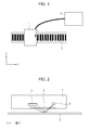
- Fig. 1 illustrates a configuration of an absolute encoder according to an embodiment.
- the absolute encoder includes a scale 2 having a sequence of marks, a detecting unit 1 (detector or reading head) configured to detect a signal corresponding to a plurality of marks of the scale 2, and a processing unit 3 (processor or controller) configured to determine an absolute position corresponding to the signal.
- the detecting unit 1 and the scale 2 may be mounted on a first object and a second object (not shown) that are relatively displaceable from each other.
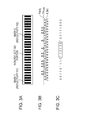
- Fig. 2 illustrates a configuration of the detecting unit 1 of the absolute encoder.
- the detecting unit 1 may include a light source 4, a light receiving element array 5 (e.g., photo-diode array), and a cover glass 6. Beams of light radiating from the light source 4 pass through the cover glass 6 to illuminate the scale 2. Then, the beams of light reflect off the scale 2 and pass through the cover glass 6 to illuminate the light receiving element array 5.
- the detecting unit 1 and the scale 2 are relatively movable in the direction along the Y-axis in the drawing (one of the detecting unit 1 and the scale 2 is typically, but not always, secured in place).
- the light receiving element array 5 may be a line sensor including light receiving elements, each having a longitudinal direction orthogonal to the direction of movement (i.e., the longitudinal direction is along the X-axis in the drawing). Since pitches of the light receiving elements are sufficiently smaller than pitches of marks of the scale 2 projected in a larger size onto the light receiving element array 5, a signal obtained by photoelectric conversion in the light receiving element array 5 has a near-sinusoidal periodic waveform.
- the scale 2 has a plurality of two or more types of marks periodically arranged at intervals.
- the marks are arranged along the direction of relative movement of the detecting unit 1 and the scale 2, and they each have a property (e.g., reflectivity or reflectance) corresponding to each code in a code sequence representing an absolute position.
- the code sequence is a 6-bit binary data sequence (binary code sequence) and may be formed by a binary pseudorandom number sequence.
- binary codes will be presented as exemplary codes that form the code sequence in the present embodiment, M-level codes (M is a natural number greater than 2) may be adopted.
- the scale 2 has reflecting and non-reflecting portions alternately arranged at regular pitches, and two types of values are adopted to represent reflectivities of the reflecting portions.
- a binary code sequence can be associated with a plurality of marks.
- a reflectivity corresponding to code 1 is represented by R1
- a reflectivity corresponding to code 0 is represented by R2.
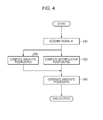
- Figs. 3A to 3C illustrate a relationship between a scale, a detection signal, and a code sequence.
- Fig. 3A illustrates the scale 2
- Fig. 3B illustrates a signal I obtained by photoelectric conversion in the light receiving element array 5
- Fig. 3C illustrates a code sequence obtained by the processing unit 3 on the basis of the signal I.
- Fig. 3A illustrates the scale 2
- Fig. 3B illustrates a signal I obtained by photoelectric conversion in the light receiving element array 5
- Fig. 3C illustrates a code sequence obtained by the processing unit 3 on the basis of the signal I.
- the scale 2 includes marks with reflectivity R1, marks with reflectivity R2 ( ⁇ R1), and non-reflecting portions with reflectivity ⁇ 0.
- the signal I has two types of amplitudes corresponding to the reflectivities R1 and R2.
- Fig. 3C shows a code sequence obtained by binarizing the signal I using a threshold TH peak . As shown, larger amplitudes of the signal I are each turned into code 1 and smaller amplitudes of the signal I are each turned into code 0.
- "001101110110100100111000" shown in Fig. 3C "110100" enclosed with a solid line is a code sequence corresponding to the absolute position.
- the code sequence corresponding to the absolute position is associated therewith with respect to each pitch of the mark sequence (mark arrangement) on the scale 2. This means that the absolute position obtained from the code sequence has a resolution of the pitch.
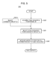
- Fig. 4 illustrates a process in which the processing unit 3 determines an absolute position Pn.
- the processing unit 3 determines an absolute position PL having a one-pitch resolution (i.e., a resolution of one pitch in the mark sequence) and an interpolation position PS having a resolution smaller than that of the absolute position PL. Then, the processing unit 3 combines the absolute position PL and the interpolation position PS to determine an absolute position P having a resolution smaller than the one pitch described above.
- the acquisition timing of acquiring the signal I is represented by Tn, and the suffix "n" is used to indicate a correspondence with the timing. Referring to Fig.
- the processing unit 3 starts the process in accordance with a request from a higher-level device or the like.
- the processing unit 3 acquires a signal In (step S10).
- the processing unit 3 determines an interpolation position PSn from the signal In (step S20) and determines an absolute position PLn from the signal In and a candidate group Cn (described below) (step S30).
- the processing unit 3 generates an absolute position Pn from the interpolation position PSn and the absolute position PLn (step S40).
- the absolute position Pn is generated by combining the absolute position PLn (higher-order bits) and the interpolation position PSn (lower-order bits).
- the processing unit 3 outputs the absolute position Pn at the end of the process.
- the process described above is performed at each acquisition timing Tn.
- Fig. 5 is a flowchart illustrating details of the process of determining the absolute position PLn (in step S30).
- the processing unit 3 first acquires a code sequence on the basis of the signal In through the binarization described above (step S300). Subsequently (or occasionally before step S300), the processing unit 3 selects a candidate group Cn for a code sequence corresponding to the absolute position PLn to be determined, on the basis of an absolute position estimated for the absolute position PLn to be determined (i.e., an estimate for the absolute position PLn) (step S300.5).
- the estimate for the absolute position PLn can be determined, for example, on the basis of an absolute position Pn- ⁇ corresponding to acquisition timing Tn- ⁇ ( ⁇ is at least one natural number greater than or equal to 1).
- the candidate group Cn corresponding to the acquisition timing Tn is a set of candidates for the code sequence to be acquired from the signal I detected at the acquisition timing Tn, and can be selected from estimates for the absolute position PLn. The details will be described later on with reference to Fig. 11 .
- the processing unit 3 selects a code sequence corresponding to the absolute position PLn from the candidate group Cn, on the basis of the distance between the code sequence based on the signal I (i.e., code sequence obtained by the binarization described above) and each of code sequences in the candidate group Cn (step S301).
- the processing unit 3 acquires the absolute position PLn corresponding to the code sequence selected in step S301 (step S302).
- the processing unit 3 outputs the absolute position PLn at the end of the process.
- the code sequence acquired in step S300 may contain errors (incorrect codes) because the waveform (amplitude etc.) of the signal In is varied by scratches or dirt on the scale 2. For example, even when marks are arranged on the scale 2 to correspond to "111111", the code sequence "110111” may be acquired if the amplitude of the signal In is partially lowered by dust adhering to the scale 2. Since "111111” and "110111" correspond to completely different absolute positions, an incorrect absolute position may be output.
- the processing unit 3 selects the candidate group Cn and then selects a code sequence in the candidate group Cn.
- the selection of a code sequence involves determining a Hamming distance Hdi between a code sequence i ("i" is a suffix for identifying the code sequence) included in the candidate group Cn and the acquired code sequence. The details will be described later on with reference to Fig. 6 .
- the Hamming distance Hdi between them is the number of digits (pairs of codes) at which the corresponding codes are different from each other.
- indexes of similarity degrees of similarity between two code sequences
- indexes such as Jaro distance, Jaro-Winkler distance, Sorensen similarity index, Czekanowski similarity index, Bray-Curtis dissimilarity, Spearman's rank correlation coefficient, and Kendall tau rank correlation coefficient are known.
- indexes as Jaro distance, Jaro-Winkler distance, Sorensen similarity index, Czekanowski similarity index, Bray-Curtis dissimilarity, Spearman's rank correlation coefficient, and Kendall tau rank correlation coefficient are known.
- there are two types of indexes the one that increases in value with decreasing similarity, such as a Hamming distance, and the other that increases in value with increasing similarity.
- a method for selecting a code sequence from the candidate group Cn on the basis of the acquired code sequence will now be described.
- code_min a code sequence i having the smallest Hamming distance to the acquired code sequence is represented by code_min, and the smallest Hamming distance is represented by Hd_min.
- code_min can be closest to the acquired code sequence, it is not clear whether code_min is the code sequence to be acquired. Therefore, it is desirable to determine whether the degree of matching of code_min with the acquired code sequence is absolutely sufficiently high, and whether the degree of matching of code_min with the acquired code sequence is relatively sufficiently high as compared to the other code sequences i in the candidate group Cn.
- the present embodiment uses two thresholds: a threshold TH A (first threshold) for the absolute degree of matching, and a threshold TH R (second threshold) for the relative degree of matching.
- the threshold TH A for the absolute degree of matching is a threshold used for Hd_min to determine whether code_min sufficiently matches the acquired code sequence. For example, assume that the number of bits in the acquired code sequence is 10 and Hd_min is 8. In this case, since there are only two code matches between the acquired code sequence and code_min, the absolute degree of matching is low. Thus, the threshold TH A for the absolute degree of matching is set, and the absolute degree of matching (high or low) is determined by whether Hd_min ⁇ TH A is satisfied.
- the threshold TH R is a threshold used to determine whether the degree of matching of code_min with the acquired code sequence is relatively high as compared to the other code sequences i in the candidate group Cn.
- a code sequence i having the second smallest Hamming distance, in the candidate group Cn, to the acquired code sequence is represented by code_min2 and the second smallest Hamming distance is represented by Hd_min2
- a value obtained by subtracting Hd_min from Hd_min2 can be used as an index indicating to what extent the degree of matching of code_min is higher than those of the other code sequences i in the candidate group Cn.
- the threshold TH R for the relative degree of matching is set, and the relative degree of matching (high or low) of code_min with respect to the other code sequences i is determined by whether Hd_min2-Hd_min > TH R is satisfied.
- code_min is selected as a code sequence corresponding to the acquired code sequence (i.e., as a code sequence corresponding to the absolute position). If at least one of the two conditions is not satisfied, a code sequence E corresponding to the estimate for the absolute position PLn described above is selected on the basis of the determination that the reliability of the acquired code sequence is low.
- Fig. 6 is a flowchart illustrating a process of selecting a code sequence.
- the processing unit 3 computes the Hamming distance between the acquired code sequence and each of code sequences in the candidate group Cn (step S3010).
- the processing unit 3 compares the resulting Hamming distances to determine the smallest Hamming distance Hd_min and the second smallest Hamming distance Hd_min2 (step S3011).
- the processing unit 3 determines whether there is only one code sequence having Hd_min (step S3012).
- the processing unit 3 determines whether Hd_min is smaller than the threshold TH A (i.e., compares Hd_min with the threshold TH A ) (step S3014). If Hd_min ⁇ TH A is satisfied, then the processing unit 3 determines whether Hd_min2-Hd_min is greater than the threshold TH R (i.e., compares Hd_min2-Hd_min with the threshold TH R ) (step S3015). If the conditions of both steps S3014 and S3015 are satisfied, the processing unit 3 selects code_min as a code sequence corresponding to the code sequence acquired with some error (step S3016).
- the processing unit 3 selects the code sequence E as a code sequence corresponding to the code sequence acquired with some error and having low reliability (step S3017). Even when there is more than one code sequence having Hd_min2 in step S3011, there is no need to change the subsequent process.
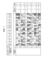
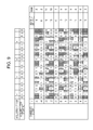
- Figs. 7 to 9 each illustrate a concrete example of selecting a code sequence. Specifically, Fig. 7 illustrates an example with no error in acquisition of a code sequence, Fig. 8 illustrates an example with a few errors in acquisition of a code sequence, and Fig. 9 illustrates an example with many errors in acquisition of a code sequence.
- the candidate group Cn includes 11 code sequences.
- the suffix "i" attached to each code sequence indicates that the code sequence provided with "i" corresponds to a mark sequence which is a distance of "scale pitch ⁇ i" away from the mark sequence corresponding to the code sequence E on the scale.
- “Hamming distance” shows the Hamming distance between the acquired code sequence and each code sequence in the candidate group Cn
- rank shows ranks assigned to Hamming distances in ascending order.
- the threshold TH A is set to 3 and the threshold TH R is set to 4.
- a plurality of code sequences for each of which the distance to the acquired code sequence is determined are limited to those in the candidate group Cn. This can have advantageous effects on improving efficiency in determining the absolute position (code sequence) and reducing errors in the absolute position. For example, as compared to the case in which the acquired code sequence is compared to all code sequences corresponding to the absolute position, the processing time can be reduced to about "the number of code sequences included in the candidate group Cn"/"the number of all code sequences".
- a code sequence acquired with errors may match a code sequence different from the original one, and an incorrect absolute position may be output.
- the present embodiment can reduce the possibility of selecting an incorrect code sequence unless such a code sequence is included in the candidate group Cn, and thus can reduce errors in the absolute position.
- Fig. 10 shows exemplary estimation of an absolute position for selecting a code sequence candidate group.
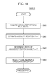
- Fig. 11 is a flowchart illustrating a process of selecting a code sequence candidate group.
- FIG. 10 shows a relationship between an already determined (previously obtained) absolute position (indicated by an open circle) and an absolute position obtained by estimation (indicated by a filled square) with respect to acquisition timing Tn for acquiring a signal I.
- An absolute position determined at acquisition timing Tn is indicated by Pn
- an absolute position obtained by estimation is indicated by Pn'
- an absolute position range corresponding to a candidate group is indicated by Pn".
- the processing unit 3 acquires an absolute position Pn-1 at timing Tn-1 and an absolute position Pn at timing Tn (step S500).
- the processing unit 3 determines the relative velocity between the detecting unit 1 and the scale 2 from (Pn-Pn-1)/(Tn-Tn-1), and estimates an absolute position Pn+1' at timing Tn+1 on the basis of the relative velocity, time (Tn+1-Tn), and the absolute position Pn (step S501).
- the processing unit 3 determines the width of an absolute position range Pn+1" for a candidate group Cn+1 at timing Tn+1 (step S502). The width may be either a fixed or variable value.
- the width can be determined, for example, on the basis of a maximum relative acceleration between the detecting unit 1 and the scale 2. Alternatively, the width may be determined by updating its value (initial value) through learning based on an actual estimation error of the absolute position.
- the processing unit 3 selects the code sequence candidate group Cn+1 on the basis of the estimated absolute position Pn+1' and the determined width of the absolute position range Pn+1" (step S503).
- the candidate group Cn+1 a code sequence corresponding to the estimated absolute position Pn+1' is referred to as the code sequence E.
- the width of the absolute position range Pn+1" for the candidate group Cn+1 is determined on the basis of the maximum relative acceleration as described above, full consideration can be given to an error in the relative velocity determined as described above. This can ensure that a code sequence corresponding to a correct absolute position at timing Tn+1 is always included in the candidate group Cn+1 (unless there is an exceptional abnormality).
- the width of the absolute position range Pn+1" for the candidate group Cn+1 may be determined by multiplying an error between the estimated absolute position Pn' and the actually obtained absolute position Pn by a safety coefficient (safety factor) K (> 1).
- the width of the absolute position range Pn+1" for the candidate group Cn+1 may be determined by various other methods depending on the application of the absolute encoder.
- the thresholds TH A and TH R described above can be used as a measure of "similar code sequences".
- a smallest Hamming distance among those between X-bit code sequences included in any candidate group Cn with an absolute position range having a predetermined width is represented by Hd xmin . If Hd xmin satisfies the following relational expression, no error occurs in selecting a code sequence in step S301: Hd xmin > TH A ⁇ 2 + TH R
- Hd 12 Hd xmin
- M e errors are those in codes for which code sequence 1 and code sequence 2 have the same value
- M u errors are those in codes for which code sequence 1 and code sequence 2 have different values.
- a code sequence to be adopted will now be described.
- a pseudorandom number sequence such as an m-sequence
- code sequences having a small Hamming distance therebetween tend to be arranged close to each other.
- Expression (1) can be satisfied by increasing the number of bits X in the code sequence acquired from the scale 2.
- Fig. 12 shows a relationship between the number of bits X in an acquired code sequence and Hd xmin .
- Hd xmin can be increased by increasing the number of bits X.
- a code sequence including codes (a start mark) indicating the starting point of the code sequence may be adopted as a code sequence corresponding to the absolute position.
- code sequences corresponding to the absolute position can be arranged in any order, code sequences having a large Hamming distance therebetween can be arranged close to each other to satisfy Expression (1).
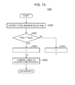
- Fig. 13 is a flowchart illustrating the process.
- the processing unit 3 extracts a local maximum value Peak j (amplitude) for each period of the signal I (see Fig. 3B ) output from the detecting unit 1 (step S3000).
- the signal I has periods and amplitudes corresponding to pitches (intervals) and properties (e.g., light reflectivities) of marks in the mark sequence on the scale 2.
- the suffix "j" of the local maximum value Peak j indicates that the local maximum value corresponds to the j-th period in the signal I.
- the processing unit 3 determines whether the local maximum value Peak j is greater than the threshold TH peak (step S3001). If the local maximum value Peak j is greater than the threshold TH peak , the processing unit 3 associates code 1 (corresponding to reflectivity R1) with the local maximum value Peak j (step S3002). If the local maximum value Peak j is not greater than the threshold TH peak , the processing unit 3 associates code 0 (corresponding to reflectivity R2) with the local maximum value Peak j (step S3003).
- a 6-bit code sequence "110100" enclosed with a solid line is a code sequence corresponding to the absolute position.
- the method for determining each code is not limited to comparison between the local maximum value and the threshold described above, but may be any method that can identify the types of marks (e.g., reflectivities R1 and R2).
- the processing unit 3 may perform a moving average that takes the average of the signal I at one-period intervals, so as to compare a moving average value corresponding to the local maximum value in each period of the signal I with a threshold. This method is effective in reducing errors in binarization, because the signal-to-noise (S/N) ratio is improved by averaging.
- the threshold TH peak may be either a fixed value prepared in advance, or a variable value determined on the basis of the signal I.
- the threshold TH peak may be independent of "j", or may be varied with "j” by taking distortion (shading etc.) in the signal detected by the detecting unit 1 into consideration.
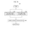
- Fig. 14 is a flowchart illustrating the process.
- the processing unit 3 acquires the interpolation position PSn with a resolution smaller than the pitch (p) of marks in the mark sequence.
- the processing unit 3 computes the inner product (or the sum of products) of the signal In and a standard function Sa producing a sine wave (sin ⁇ ) having the same period as the signal In, and also computes the inner product (or the sum of products) of the signal In and a standard function Sb producing a cosine wave (cos ⁇ ) having the same period as the signal In (steps S200 and S201):
- a is a coefficient determined by the amplitude of the signal I
- ⁇ is a phase difference between the signal In and the standard function Sa (Sb)
- ⁇ s and ⁇ c are determined by the phase difference ⁇ and a difference between two amplitudes at both ends of the signal In.
- the present embodiment can provide an absolute encoder which is advantageous in terms of efficiency and accuracy in selecting a code sequence.
- the scale 2 may be of a transmissive type. Although a single-track scale is shown as an example, the scale 2 may be a multi-track scale having absolute tracks (for absolute positions) and incremental tracks (for interpolation positions).
- a code sequence represented by a mark sequence is a pseudorandom number sequence in the embodiments described above, the code sequence is not limited to this. For example, the beginning of each code sequence (corresponding to the absolute position) may be marked by a start symbol, as described in PCT Japanese Translation Patent Publication No. 2004-529344 .
- Such code sequences have more freedom in the arrangement of code sequences corresponding to the absolute position than pseudorandom number sequences, and thus can be more easily prepared.
- the scale 2 may be a non-linear scale, such as a rotary scale (e.g., disk(-shaped), annular, or cylindrical scale).
- a rotary scale e.g., disk(-shaped), annular, or cylindrical scale.
- an absolute encoder for determining a one-dimensional absolute position is shown as an example, the absolute encoder is not limited to this, and may be one for determining a two-dimensional or three-dimensional absolute position.
- the detecting unit 1 is configured such that one period of a light signal from the scale 2 is detected by 12 light receiving elements, third or higher order harmonic components can be effectively reduced even when the distribution of light over the light receiving element array 5 does not form a sine wave. This makes it possible to determine an interpolation position with high precision.
- the number of light receiving elements for one period is not limited to this. In view of required precision and availability of components (light receiving element array etc.), the number of light receiving elements for one period may be three, four, six, or eight.
- the numerical expressions or values used in the computations described above may be changed to accommodate variation in sensitivity among elements of the light receiving element array 5 and unevenness in the distribution of light caused by the optical system. Approximate values appropriate for required precision may be used.
- the processing unit 3 may include a series or parallel analog processing circuit, and at least one of an analog-to-digital (A/D) converter and a digital processing circuit.
- A/D analog-to-digital
- the absolute position Pn and the interpolation position PSn are combined to generate the absolute position Pn in the embodiment described above, the absolute position Pn may be generated by other methods. For example, in accordance with the level of resolution required for the operation mode or the intended use of the apparatus including the absolute encoder, only the absolute position PLn may be generated, either always or at appropriate times. In this case, the function of generating the interpolation position PSn may be removed or stopped.
- the detecting unit 1 includes the light receiving element array 5 in the embodiment described above, the configuration is not limited to this.
- the detecting unit 1 may include an array of various elements. That is, the elements may be of any type as long as they detect physical quantities corresponding to the properties that identify multiple types of marks.
- the detecting unit 1 may include an array of magnetic (magnetic field) detectors, such as Hall elements.
- the embodiments described above may also be realized by performing the processing described below. That is, the processing is performed by supplying software (program) implementing the functions of the above-described embodiments to a system or apparatus via a network or various types of storage media, and causing a computer (or central processing unit (CPU) or micro-processing unit (MPU)) of the system or apparatus to read and execute the program.
- the computer corresponds to the processing unit 3 described above.
- the absolute encoder does not require the operation for detecting the origin (reference position), and thus is useful when used with various driving machines or apparatuses, and robots, transport machines or apparatuses, and industrial machines or apparatuses (including machines or apparatuses for machining, processing, measuring, and manufacturing) that include the driving apparatuses.
- a driving apparatus may include a movable unit (movable device), an absolute encoder that measures the absolute position for movement of the movable unit, and a driving unit (driving device or actuator) that performs driving (a driving operation) associated with the motion (the movement) of the movable unit on the basis of the output from the absolute encoder.
- Fig. 15 illustrates a configuration of a stage device 1000 in the present application.
- a lithography apparatus is an apparatus that forms a pattern on a substrate, and can be embodied, for example, as an exposure apparatus, a drawing apparatus, or an imprint apparatus.
- the exposure apparatus forms a pattern (latent image pattern) on a substrate (or resist on the substrate) using, for example, ultraviolet (extreme ultraviolet) radiation.
- the drawing apparatus forms a pattern (latent image pattern) on a substrate (or resist on the substrate) using, for example, charged particle beams (e.g., electron beams).
- the imprint apparatus forms a pattern on a substrate by molding an imprint material on the substrate.
- the stage device 1000 includes Y-axis motors 1009 (driving device) used for moving a stage 1008 (movable device) in the Y-axis direction, and an X-axis motor 1012 (driving device) used for moving the stage 1008 in the X-axis direction.
- the absolute position of the stage 1008 can be obtained, for example, by mounting the scale 2 of the absolute encoder on one of a stator and a moving member of each motor, and mounting the detecting unit 1 of the absolute encoder on the other of the stator and the moving member of the motor.
- Embodiment(s) of the present invention can also be realized by a computer of a system or apparatus that reads out and executes computer executable instructions (e.g., one or more programs) recorded on a storage medium (which may also be referred to more fully as a 'non-transitory computer-readable storage medium') to perform the functions of one or more of the above-described embodiment(s) and/or that includes one or more circuits (e.g., application specific integrated circuit (ASIC)) for performing the functions of one or more of the above-described embodiment(s), and by a method performed by the computer of the system or apparatus by, for example, reading out and executing the computer executable instructions from the storage medium to perform the functions of one or more of the above-described embodiment(s) and/or controlling the one or more circuits to perform the functions of one or more of the above-described embodiment(s).
- computer executable instructions e.g., one or more programs
- a storage medium which may also be referred to more fully as
- the computer may comprise one or more processors (e.g., central processing unit (CPU), micro processing unit (MPU)) and may include a network of separate computers or separate processors to read out and execute the computer executable instructions.
- the computer executable instructions may be provided to the computer, for example, from a network or the storage medium.
- the storage medium may include, for example, one or more of a hard disk, a random-access memory (RAM), a read only memory (ROM), a storage of distributed computing systems, an optical disk (such as a compact disc (CD), digital versatile disc (DVD), or Blu-ray Disc (BD)TM), a flash memory device, a memory card, and the like.
Landscapes
- Physics & Mathematics (AREA)
- General Physics & Mathematics (AREA)
- Engineering & Computer Science (AREA)
- Automation & Control Theory (AREA)
- Transmission And Conversion Of Sensor Element Output (AREA)
- Optical Transform (AREA)
Applications Claiming Priority (1)
| Application Number | Priority Date | Filing Date | Title |
|---|---|---|---|
| JP2014083137A JP6497848B2 (ja) | 2014-04-14 | 2014-04-14 | アブソリュートエンコーダ、処理方法、プログラム、駆動装置、および産業機械 |
Publications (1)
| Publication Number | Publication Date |
|---|---|
| EP2937672A1 true EP2937672A1 (fr) | 2015-10-28 |
Family
ID=52814913
Family Applications (1)
| Application Number | Title | Priority Date | Filing Date |
|---|---|---|---|
| EP15163049.8A Withdrawn EP2937672A1 (fr) | 2014-04-14 | 2015-04-09 | Codeur absolu, procédé de traitement, programme, appareil d'entraînement et machine industrielle |
Country Status (3)
| Country | Link |
|---|---|
| US (1) | US10209104B2 (fr) |
| EP (1) | EP2937672A1 (fr) |
| JP (1) | JP6497848B2 (fr) |
Families Citing this family (6)
| Publication number | Priority date | Publication date | Assignee | Title |
|---|---|---|---|---|
| JP6705649B2 (ja) * | 2015-12-22 | 2020-06-03 | 株式会社ミツトヨ | エンコーダ |
| JP6664211B2 (ja) * | 2015-12-22 | 2020-03-13 | 株式会社ミツトヨ | エンコーダ |
| ES2752656T3 (es) * | 2017-08-01 | 2020-04-06 | Fagor Automation S Coop | Método de comprobación para un dispositivo optoelectrónico de medida, y dispositivo |
| JP7258515B2 (ja) | 2018-10-26 | 2023-04-17 | Dmg森精機株式会社 | 位置検出装置および搬送装置 |
| JP6842680B2 (ja) * | 2019-07-19 | 2021-03-17 | 株式会社安川電機 | エンコーダ、サーボモータ、サーボシステム |
| US11808610B2 (en) | 2021-02-09 | 2023-11-07 | Asahi Kasei Microdevices Corporation | Position detection apparatus, position detection system, and position detection method |
Citations (3)
| Publication number | Priority date | Publication date | Assignee | Title |
|---|---|---|---|---|
| EP0789226A1 (fr) * | 1996-02-10 | 1997-08-13 | Dr. Johannes Heidenhain GmbH | Dispositif de mesure de positions |
| DE19638912A1 (de) * | 1996-09-23 | 1998-03-26 | Teves Gmbh Alfred | Drehwinkelsensor mit CCD-Zeile und periodisch angesteuerter Lichtquelle |
| US20040118758A1 (en) * | 2001-04-11 | 2004-06-24 | Gordon-Ingram Iain Robert | Absolute position measurement |
Family Cites Families (10)
| Publication number | Priority date | Publication date | Assignee | Title |
|---|---|---|---|---|
| DE19830925A1 (de) * | 1997-08-07 | 1999-02-11 | Heidenhain Gmbh Dr Johannes | Abtasteinheit für eine optische Positionsmeßeinrichtung |
| TW575518B (en) * | 2001-07-31 | 2004-02-11 | Inventio Ag | Lift installation with a measuring system for determining absolute cage position |
| GB0200575D0 (en) * | 2002-01-11 | 2002-02-27 | Rls Merilna Tehnika D O O | Encoder with reference marks |
| US6664535B1 (en) * | 2002-07-16 | 2003-12-16 | Mitutoyo Corporation | Scale structures and methods usable in an absolute position transducer |
| DE112009002101T5 (de) * | 2008-08-28 | 2012-01-12 | Faro Technologies, Inc. | Mit einem Index versehender optischer Encoder, Verfahren zum Indexieren eines optischen Encoders und Verfahren zum dynamischen Einstellen von Verstärkung und Offset in einem optischen Encoder |
| JP2011112520A (ja) * | 2009-11-27 | 2011-06-09 | Sony Corp | 位置検知装置、撮像装置および位置検知方法 |
| JP5434617B2 (ja) * | 2010-01-19 | 2014-03-05 | 株式会社ニコン | エンコーダ装置 |
| JP5381754B2 (ja) * | 2010-01-29 | 2014-01-08 | 株式会社ニコン | エンコーダ |
| JP5379761B2 (ja) * | 2010-08-06 | 2013-12-25 | キヤノン株式会社 | アブソリュートエンコーダ |
| JP2013221795A (ja) * | 2012-04-13 | 2013-10-28 | Nikon Corp | エンコーダ、及び駆動装置 |
-
2014
- 2014-04-14 JP JP2014083137A patent/JP6497848B2/ja not_active Expired - Fee Related
-
2015
- 2015-04-09 EP EP15163049.8A patent/EP2937672A1/fr not_active Withdrawn
- 2015-04-13 US US14/685,032 patent/US10209104B2/en not_active Expired - Fee Related
Patent Citations (4)
| Publication number | Priority date | Publication date | Assignee | Title |
|---|---|---|---|---|
| EP0789226A1 (fr) * | 1996-02-10 | 1997-08-13 | Dr. Johannes Heidenhain GmbH | Dispositif de mesure de positions |
| DE19638912A1 (de) * | 1996-09-23 | 1998-03-26 | Teves Gmbh Alfred | Drehwinkelsensor mit CCD-Zeile und periodisch angesteuerter Lichtquelle |
| US20040118758A1 (en) * | 2001-04-11 | 2004-06-24 | Gordon-Ingram Iain Robert | Absolute position measurement |
| JP2004529344A (ja) | 2001-04-11 | 2004-09-24 | レニショウ パブリック リミテッド カンパニー | アブソリュート位置測定法 |
Also Published As
| Publication number | Publication date |
|---|---|
| JP6497848B2 (ja) | 2019-04-10 |
| JP2015203625A (ja) | 2015-11-16 |
| US10209104B2 (en) | 2019-02-19 |
| US20150292919A1 (en) | 2015-10-15 |
Similar Documents
| Publication | Publication Date | Title |
|---|---|---|
| EP2937672A1 (fr) | Codeur absolu, procédé de traitement, programme, appareil d'entraînement et machine industrielle | |
| CN100516780C (zh) | 采用串联多比特内插子编码器的绝对编码器 | |
| TWI519766B (zh) | 位置判定方法及裝置 | |
| US8785838B2 (en) | Absolute rotary encoder | |
| CN104048686B (zh) | 位置检测装置、透镜装置、摄像系统和机床装置 | |
| EP2416126B1 (fr) | Codeur absolu | |
| EP2466267B1 (fr) | Encodeur rotatif absolu | |
| EP3035003B1 (fr) | Appareil de détection de position, appareil de lentille, système de capture d'image, appareil de machine-outil, procédé de détection de position, programme et support de stockage | |
| Kim et al. | Absolute angle measurement using a phase-encoded binary graduated disk | |
| US9417102B2 (en) | Absolute encoder, signal processing method, program, driving apparatus, and industrial machine | |
| US9880028B2 (en) | Absolute encoder | |
| US20150130931A1 (en) | Position detecting apparatus, and lens apparatus and image pickup apparatus including the position detecting apparatus | |
| US10190893B2 (en) | Encoder | |
| JP6440609B2 (ja) | 位置検出装置、レンズ装置、撮像システム、工作装置、露光装置、位置検出方法、プログラム、記憶媒体 | |
| EP3663724B1 (fr) | Encodeur rotatif absolu et appareil | |
| EP2778626B1 (fr) | Appareil de détection de position, appareil de lentille, système de capture d'image, appareil de machine-outil, procédé de détection de position, programme et support de stockage | |
| JP6087722B2 (ja) | 原点信号発生装置及び原点信号発生システム | |
| EP2733469B1 (fr) | Appareil de mesure, procédé de mesure et codeur absolu | |
| JP2017044500A (ja) | アブソリュートエンコーダ、駆動装置および産業装置 | |
| JP4945976B2 (ja) | 光学式絶対値エンコーダ |
Legal Events
| Date | Code | Title | Description |
|---|---|---|---|
| PUAI | Public reference made under article 153(3) epc to a published international application that has entered the european phase |
Free format text: ORIGINAL CODE: 0009012 |
|
| AK | Designated contracting states |
Kind code of ref document: A1 Designated state(s): AL AT BE BG CH CY CZ DE DK EE ES FI FR GB GR HR HU IE IS IT LI LT LU LV MC MK MT NL NO PL PT RO RS SE SI SK SM TR |
|
| AX | Request for extension of the european patent |
Extension state: BA ME |
|
| 17P | Request for examination filed |
Effective date: 20160428 |
|
| RBV | Designated contracting states (corrected) |
Designated state(s): AL AT BE BG CH CY CZ DE DK EE ES FI FR GB GR HR HU IE IS IT LI LT LU LV MC MK MT NL NO PL PT RO RS SE SI SK SM TR |
|
| GRAP | Despatch of communication of intention to grant a patent |
Free format text: ORIGINAL CODE: EPIDOSNIGR1 |
|
| STAA | Information on the status of an ep patent application or granted ep patent |
Free format text: STATUS: THE APPLICATION HAS BEEN WITHDRAWN |
|
| INTG | Intention to grant announced |
Effective date: 20181008 |
|
| 18W | Application withdrawn |
Effective date: 20181004 |