EP2937730A1 - Brillenglas - Google Patents
Brillenglas Download PDFInfo
- Publication number
- EP2937730A1 EP2937730A1 EP13866155.8A EP13866155A EP2937730A1 EP 2937730 A1 EP2937730 A1 EP 2937730A1 EP 13866155 A EP13866155 A EP 13866155A EP 2937730 A1 EP2937730 A1 EP 2937730A1
- Authority
- EP
- European Patent Office
- Prior art keywords
- pair
- spectacle lenses
- refractive
- lens
- spectacle
- Prior art date
- Legal status (The legal status is an assumption and is not a legal conclusion. Google has not performed a legal analysis and makes no representation as to the accuracy of the status listed.)
- Granted
Links
Images




Classifications
-
- G—PHYSICS
- G02—OPTICS
- G02C—SPECTACLES; SUNGLASSES OR GOGGLES INSOFAR AS THEY HAVE THE SAME FEATURES AS SPECTACLES; CONTACT LENSES
- G02C7/00—Optical parts
- G02C7/02—Lenses; Lens systems ; Methods of designing lenses
- G02C7/06—Lenses; Lens systems ; Methods of designing lenses bifocal; multifocal ; progressive
- G02C7/061—Spectacle lenses with progressively varying focal power
- G02C7/068—Special properties achieved by the combination of the front and back surfaces
-
- G—PHYSICS
- G02—OPTICS
- G02C—SPECTACLES; SUNGLASSES OR GOGGLES INSOFAR AS THEY HAVE THE SAME FEATURES AS SPECTACLES; CONTACT LENSES
- G02C7/00—Optical parts
- G02C7/02—Lenses; Lens systems ; Methods of designing lenses
- G02C7/024—Methods of designing ophthalmic lenses
- G02C7/027—Methods of designing ophthalmic lenses considering wearer's parameters
-
- G—PHYSICS
- G02—OPTICS
- G02C—SPECTACLES; SUNGLASSES OR GOGGLES INSOFAR AS THEY HAVE THE SAME FEATURES AS SPECTACLES; CONTACT LENSES
- G02C7/00—Optical parts
- G02C7/02—Lenses; Lens systems ; Methods of designing lenses
- G02C7/06—Lenses; Lens systems ; Methods of designing lenses bifocal; multifocal ; progressive
- G02C7/061—Spectacle lenses with progressively varying focal power
-
- G—PHYSICS
- G02—OPTICS
- G02C—SPECTACLES; SUNGLASSES OR GOGGLES INSOFAR AS THEY HAVE THE SAME FEATURES AS SPECTACLES; CONTACT LENSES
- G02C7/00—Optical parts
- G02C7/02—Lenses; Lens systems ; Methods of designing lenses
- G02C7/06—Lenses; Lens systems ; Methods of designing lenses bifocal; multifocal ; progressive
- G02C7/061—Spectacle lenses with progressively varying focal power
- G02C7/063—Shape of the progressive surface
- G02C7/065—Properties on the principal line
Definitions
- Fig. 1 is a block diagram illustrating a configuration of a spectacle lens manufacturing system 1 according to the embodiment.
- the spectacle lens manufacturing system 1 includes an optical store 10 which orders spectacle lenses according to a prescription for a customer (a wearer), and a spectacle lens manufacturing factory 20 which manufactures spectacle lenses after receiving the order from the optical store 10.
- the order to the spectacle lens manufacturing factory 20 is issued through a predetermined network, such as the Internet, or data transmission by, for example, facsimile.
- Orderers may include ophthalmologists or general consumers.
- a store computer 100 is installed.
- the store computer 100 is, for example, a general PC (Personal Computer), and software for ordering spectacle lenses to the spectacle lens manufacturing factory 20 has been installed in the store computer 100.
- lens data and frame data are input through an operation to a mouse or a keyboard by an optical store staff.
- the frame data includes shape data of a frame selected by a customer.
- the frame data is managed, for example, by barcode tags, and can be obtained by reading a barcode tag adhered to a frame by a barcode reader.
- the store computer 100 transmits the ordering data (the lens data and the frame data) to the spectacle lens manufacturing factory 20 via, for example, the Internet.
- the spectacle lens design computer 202 On the spectacle lens design computer 202, a program for designing spectacle lenses corresponding to an order has been installed, and generates lens design data based on the ordering data (lens data) and generates edge processing data based on the ordering data (frame data). Design of spectacle lenses by the spectacle lens design computer 202 is explained in detail later.
- the spectacle lens design computer 202 transfers generated lens design data and the edge processing data to the spectacle lens processing computer 204.
- An operator sets a block piece on a processing machine 206, such as a curve generator, and inputs an instruction for start of processing to the spectacle lens processing computer 204.
- the spectacle lens processing computer 204 reads the lens design data and the edge processing data transferred from the spectacle lens design computer 202, and drives and controls the processing machine 206.
- the processing machine 206 performs grinding and polishing for inner and outer surfaces of the block piece in accordance with the lens design data, and generates the inner surface shape and the outer surface shape of the spectacle lens. Further, the processing machine 206 processes the outer peripheral surface of an uncut lens after generation of the inner surface shape and the outer surface shape so that the uncut lens has the peripheral shape corresponding to the edge shape.
- the spectacle lens after the edge processing is provided with various types of coatings, such as, dyeing processing, hard coating, anti-reflection coating and ultraviolet light cutting.
- coatings such as, dyeing processing, hard coating, anti-reflection coating and ultraviolet light cutting.
- the present design process may be applied to spectacle lenses of another type of item group (being a pair of spectacle lenses having left and right dioptric powers different from each other at predetermined reference points) having a progressive power portion in which the refractive power changes progressively, such as a intermediate-near progressive power lens or a near-near progressive power lens of a one side progressive surface type, a both side progressive surface type and an integrated double surface type.
- a progressive power portion in which the refractive power changes progressively such as a intermediate-near progressive power lens or a near-near progressive power lens of a one side progressive surface type, a both side progressive surface type and an integrated double surface type.
- a wearer of anisometropia when a wearer of anisometropia performs binocular vision for a near object point, a shift occurs between left and right visual lines due to the difference in prismatic effects which correspond to the difference in prescribed dioptric powers. Specifically, the wearer performs binocular vision through points other than a near reference point N (a point having the addition of 2.50D at which the dioptric power for a near portion is set) laid out on the lens.
- N a point having the addition of 2.50D at which the dioptric power for a near portion is set
- the wearer is forced to view the near object point in a state where a burden is imposed on the eyes, i.e., a state where addition effects actually acting on the left and right eyes are different from each other.
- a burden is imposed on the eyes
- the addition effect substantially acting on the eyes is also referred to as "substantive addition”.
- the inventor has found that as the degree of difference between prescribed distance dioptric powers for the left and right eyes increases and also as the object distance becomes short, the difference between the substantive additions for the left and right eyes increases.
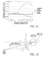
- Fig. 12 as an example where the difference between the substantive additions for the left and right eyes becomes large, a state where a wearer views a near object point is illustrated. That is, the inventor has also found that the above described problem occurs not only in a case of a short distance but also in a case of a distance (e.g., a long distance or an intermediate distance) farther than the short distance.
- spectacle lenses capable of ensuring suitable binocular vision at each object distance (from a long distance to a short distance) while resolving the above described problem are designed.
- the design process of spectacle lenses by the spectacle lens design computer 202 is specifically explained.
- the spectacle lens design computer 202 defines a reference lens based on a prescription for a wearer received from the store computer 100 via the host computer 200.
- the reference lens is a spectacle lens hypothetically defined, common to the left and right eyes, in accordance with the fact that physiologically the degrees of accommodation acting on the left and right eyes are equal to each other, and is configured such that the distance dioptric power is set to a common average value of the left and right prescribed distance dioptric powers. That is, the reference lens is a spectacle lens having a progressive power portion, and has the distance dioptric power and the addition power common to the left and right.
- the distance dioptric power of the reference lens is defined as a reference dioptric power.
- the reference lens has: reference dioptric power (right): S+3.00 ADD2.50 reference dioptric power (left): S+3.00 ADD2.50 It should be noted that, in this embodiment, explanation is given about the sequence where a right eye lens and a left eye lens are designed concurrently; however, in another embodiment the sequence may be performed such that one lens is designed first and thereafter the other lens is designed.
- reference numbers for the right eye are assigned a subscript of a letter R
- reference numbers for the left eye are assigned a subscript of a letter L.
- these subscriptions are not assigned.
- the eye axis lengths of eyeballs differ between hyperopia and myopia.
- the spectacle lens design computer 202 stores in advance information on how the eye axis lengths differ depending on degrees of hyperopia and myopia.
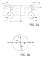
- the spectacle lens design computer 202 chooses a suitable eyeball model E according to the prescription (a spherical power, a cylindrical power) of a wearer included in the ordering data, and disposes the chosen eyeball model E in a hypothetical model space as shown in Fig. 3A . More specifically, an eyeball model E R and an eyeball model E L are disposed such that an eyeball rotation center O ER and an eyeball rotation center O EL are separated by a pupillary distance PD.
- a tangential plane to the reference lens model L B at the outer surface vertex is defined as a tangential plane TP
- an intersection between a visual line of the eyeball model E R in a front view and the tangential plane TP is defined as a reference point P TPR
- an intersection between a visual line of the eyeball model E L in a front view and the tangential plane TP is defined as a reference point P TPL
- These reference points P TP are lens design centers, and the lens design center is an intermediate point between a pair of hidden marks (which are described later).
- Fig. 3B generally illustrates a layout of the spectacle lens defined by the present design process.
- the spectacle lens according to the embodiment is configured such that, on the principal meridian LL', a distance reference point F (a point at which the dioptric power for a distance portion is set) is disposed on the upper side of the lens design center, and a near reference point N is disposed on the lower side of the lens design center.
- the principal meridian LL' is shifted inward to the nose side considering the convergence of eyes, from an intermediate point of a progressive zone toward the near reference point N. Positions of the near reference point N and the distance reference point F are identified based on the pair of hidden marks M directly marked on a lens surface.
- the spectacle lens according to the embodiment is configured such that the lengths and the widths of the progressive power zones are different from each other between the left and right. Therefore, positions of the near reference points N and the distance reference points F on the lens surface are different from each other between the left and right.
- the spectacle lens design computer 202 defines, common to the left and right, a reference object surface including a plurality of object surfaces disposed at different object distances, in accordance with the fact that physiologically the degrees of accommodation of the left and right eyes are equal to each other, based on the reference lens model L B .
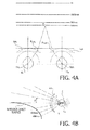
- Each of Figs. 4A and 4B illustrates the reference object surface common to the left and right defined in the hypothetical model space.
- the reference object surface is a single continuous surface smoothly connecting the object surfaces disposed at the respective object distances; however, in Fig. 4A , of the object surfaces, only discrete object surfaces used for design of the spectacle lenses are illustrated for convenience of explanation.
- Fig. 4A of the object surfaces
- the object surfaces used for design of the spectacle lenses include object surfaces disposed at an object distance corresponding to the near dioptric power (a targeted short work distance (close work distance) and is 400mm in this case), an object distance corresponding to the dioptric power at sample points on the principal meridian LL' in the progressive zone (500mm, ⁇ 1000mm, ⁇ ), and an object distance (a distance which can be regarded as an infinite distance, such as 5000mm) corresponding to the distance dioptric power (the reference dioptric power).
- the object surface is defined at a position away from the line connecting the eyeball rotation center O ER and the eyeball rotation center O EL by an object distance corresponding to each dioptric power; however, in another embodiment the object surface may be defined at a position on an eye front hemisphere which has the center at the intermediate point between the eyeball rotation center O ER and the eyeball rotation center O EL and has the radius equal to the object distance corresponding to each dioptric power.
- the reference object surface common to the left and right is defined based on the hypothetical reference lens model L B before spectacle lenses are designed (or independently of design of spectacle lenses) as described above.
- an index indicating at which distance a wearer views an object in the case where the left and right prescribed dioptric powers are different from each other is defined in advance in common for the left and right in accordance with the fact that physiologically the degrees of accommodation of the left and right eyes are equal to each other, and the following lens design process is performed. Therefore, a conventional problem that when the prescribed dioptric powers of the left and right are different from each other, the object surfaces of the left and right are different from each other can be avoided.
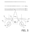
- the spectacle lens design computer 202 calculates positions (Reference side chief ray passing positions P LBR and P LBL ) on the left and right reference lens models L BR and L BL (on the outer surfaces) at which chief rays (a chain line) from an arbitrary point P on the object surface pass, by performing an optical calculation process using, for example, ray tracing.
- the chief ray is defined as a light ray proceeding from the arbitrary point P on the reference object surface to the eyeball rotation center O E .
- the spectacle lens design computer 202 calculates the reference side chief ray passing position P LB corresponding to each point on each object surface so that the reference side chief ray passing position P LB is disposed on the entire outer surface of the reference lens model L B .
- each arbitrary point P on each object surface used for calculation of step S4 is referred to as a chief ray start point P.
- the lens design is performed on the premise that the curvature distribution (curvature distribution corresponding to the transmission power distribution) exists only on the outer surface of various lens models.
- the spectacle lens design computer 202 defines a reference sphere SR as an evaluation surface for evaluating a targeted transmission dioptric power.
- the reference sphere SR is a sphere which has the center at the eyeball rotation center O E of the eyeball model E and has a radius equal to a distance from the eyeball rotation center O E to the rear vertex of the reference lens model L B .
- the spectacle lens design computer 202 calculates the transmission dioptric power on the reference sphere SR for the light ray passing through the near reference point N of the reference lens model L B .
- the transmission dioptric power calculated herein is a near dioptric power of the reference lens model L B
- the reference addition ADD S is defined as a value obtained by subtracting the near dioptric power from the distance dioptric power.
- the reference addition ADD S becomes a targeted dioptric power (ADD 2.50) common to the left and right.
- the spectacle lens design computer 202 changes the hypothetical optical model constructed in step S2 in Fig. 2 to another hypothetical optical model having eyeballs and spectacle lenses defined on the assumption that the wearer wears the spectacle lenses (prescribed lens (right): S+2.00 ADD2.50, prescribed lens (left): S+4.00 ADD2.50).
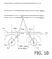
- Fig. 6 illustrates an example of the hypothetical optical model after change by the spectacle lens design computer 202.
- the spectacle lens design computer 202 disposes the prescribed lens models L PR and L PL respectively corresponding to the prescribed lenses (right and left) for the eyeball models E R and E L .
- the prescribed lens model L P is defined by a known design method based on the prescription, and detailed explanation thereof will be omitted. In the prescribed lens model L P at this stage, shift of the right and left visual lines are caused by the difference between the right and left prismatic effects.
- the spectacle lens design computer 202 disposes the prescribed lens model L PR such that the outer surface vertex is situated at the reference point P TPR and the lens contacts the tangential plane TP at the outer surface vertex, and disposes the prescribed lens model L PL such that the outer surface vertex is situated at the reference point P TPL and the lens contacts the tangential plane TP at the outer surface vertex.
- the center thickness of the prescribed lens model Lp is also determined based on the prescription and the refractive index of the glass material.
- the spectacle lens design computer 202 calculates positions (prescribed side chief ray passing positions P LPR and P LPL ) on the prescribed lens models L PR and L PL (on the outer surface in this case) at which the chief rays (a solid line) from each chief ray start point P (i.e., an arbitrary point P on the object surface defined in common for the left and right in accordance with the fact that physiologically the degrees of accommodation for the left and right are equal to each other) used in step S4 in Fig. 2 (calculation of chief ray passing position on reference lens model L B ) pass, by executing an optical calculation process using, for example, ray tracing.
- the prescribed side chief ray passing position P LP is disposed on the entire outer surface of the prescribed lens model L P .
- a distance between the reference point P TP and the reference side chief ray passing position P LB is defined as a reference side distance D LB
- a distance between the reference point P TP and the prescribed side chief ray passing position P LP is defined as a prescribed side distance D LP
- the prescribed lens model L PR Since the prescribed lens model L PR has the prescribed dioptric power (S+2.00) which is on the minus side with respect to the reference dioptric power (S+3.00), the prescribed side chief ray passing position P LPR becomes closer to the reference point P TPR than the reference side chief ray passing position P LBR on the principal meridian LL' (see Fig. 7A ). As shown by a solid line in Fig. 7B , the correction ratio R R becomes smaller, in response to the difference between the prismatic effects of the prescribed lens model L PR and the reference lens model L BR , as the prescribed side distance D LPR becomes long (as the prescribed side chief ray passing position P LPR moves away from the reference point P TPR and thereby approaches the near reference point N).
- the reference side chief ray passing position P LBR becomes closer to the reference point P TPL than the prescribed side chief ray passing position P LPL on the principal meridian LL' (see Fig. 7A ). As shown in by a solid line in Fig.
- the correction ratio R L becomes larger, in response to the difference between the prismatic effects of the prescribed lens model L PL and the reference lens model L BL , as the prescribed side distance D LPL becomes long (as the prescribed side chief ray passing position P LPL moves away from the reference point P TPL and thereby approaches the near reference point N).
- the spectacle lens design computer 202 corrects the curvature distribution of the prescribed lens model L P by executing the enlarging or reducing operation, based on the correction ratio R corresponding to each chief ray start point P, for the curvature distribution (hereafter referred to as "progressive distribution", which is a distribution obtained by extracting only a curvature distribution adding a progressive power component, of the whole curvature distribution of the lens) providing the progressive refractive power assumed for the reference lens model L B .
- progressive distribution which is a distribution obtained by extracting only a curvature distribution adding a progressive power component, of the whole curvature distribution of the lens
- the reference progressive distribution (the progressive distribution of the reference lens model L B ) is corrected by enlarging or reducing the reference progressive distribution in accordance with the corresponding correction ratio R, and the corrected progressive distribution of the reference lens model L B is applied as the progressive distribution of the prescribed lens model Lp.
- (curvature K(x,y) of the progressive distribution of the prescribed lens) (curvature K(x/Rx, y/Ry) of the progressive distribution of the reference lens) where x and y denote coordinates of the prescribed side chief ray passing position P LP , and Rx and Ry denote the correction ratio R in the x direction and y direction.
- the curvature relating to the progressive refractive power effect at the position P LPR on the prescribed lens model L PR i.e., curvature which is defined by excluding a component by the distance dioptric power and which is a curvature component adding the addition effect
- curvature relating to the progressive refractive power effect at the position P LBR on the reference lens model L BR is operated so as to coincide with the curvature relating to the progressive refractive power effect at the position P LBR on the reference lens model L BR .
- the curvature corresponding to the addition effect at the reference side chief ray passing position P LBR is relocated to the prescribed side chief ray passing position P LPR corresponding to the correction ratio R R . Since the correction ratio R R differs between positions, change of addition after correction in the progressive zone becomes different in shape from change of addition in the progressive zone of the reference lens model L BR depending on the correction ratio R R (for example, the changing ratio of addition becomes larger as a point approaches the near reference point N from the reference point P TPR ).
- the entire progressive distribution is reduced, in accordance with the correction ratio R R , with respect to the progressive distribution of the reference lens model L BR , and therefore the length of the progressive zone becomes short and the width of the progressive zone becomes narrow.
- the curvature corresponding to the addition effect at the reference side chief ray passing position P LBL is relocated to the prescribed side chief ray passing position P LPL corresponding to the correction ratio R L . Since the correction ratio R L differs between positions, change of the addition after correction in the progressive zone becomes different in shape from change of addition in the progressive zone of the reference lens model L BL depending on the correction ratio R L (for example, the changing ratio of addition becomes smaller as a point approaches the near reference point N from the reference point P TPL ).
- the entire progressive distribution is enlarged, in accordance with the correction ratio R L , with respect to the progressive distribution of the reference lens model L BL , and therefore the length of the progressive zone becomes long and the width of the progressive zone becomes wide.
- the problem shown in Fig. 12 also occurs at another object distance, such as an intermediate object distance, although in such a case the degree of the problem is not so serious with respect to the case of viewing at a short distance. Therefore, according to the embodiment, as can be seen from the correction ratio R shown in Figs. 7B and 7C , the difference between the substantive additions of the left and right caused when an object at an intermediate distance is viewed is suitably reduced through the suitable enlarging or reducing operation for the curvature distribution (the progressive distribution).
- Fig. 8A illustrates an example of the transmission dioptric power distribution on the reference sphere SR of the reference lens model L B .
- the transmission dioptric power distribution illustrated herein is the astigmatism distribution and the average dioptric power distribution, and is equivalent to the curvature distribution.
- Fig. 8B illustrates an example of the transmission dioptric power distribution on the reference sphere SR of the prescribed lens model L PR
- Fig. 8C illustrates an example of the transmission dioptric power distribution on the reference sphere SR of the prescribed lens model L PL .
- the transmission dioptric power distribution (i.e., the curvature distribution) of the prescribed lens model L PR illustrated as an example in Fig. 8B has been subjected to the reducing operation according to the correction ratio R R at each prescribed side chief ray passing position P LPR . That is, contour lines of the astigmatism distribution and contour lines of the average dioptric power distribution are reduced in accordance with the correction ratio R R , and basically as the prescribed side chief ray passing position P LPR moves away from the reference point P TPR , the shape of the contour lines are further reduced.
- the transmission dioptric power distribution (i.e., the curvature distribution) of the prescribed lens model L PL illustrated as an example in Fig. 8C has been subjected to the enlarging operation according to the correction ratio R L at each prescribed side chief ray passing position P LPL . That is, contour lines of the astigmatism distribution and contour lines of the average dioptric power distribution are enlarged in accordance with the correction ratio R L , and basically as the prescribed side chief ray passing position P LPL moves away from the reference point P TPL , the shape of the contour lines are further enlarged.
- the spectacle lens design computer 202 allocates the curvature distribution of the prescribed lens model L P corrected in step S9 in Fig. 2 to the outer surface and the inner surface of the prescribed lens model Lp in accordance with a structure (an inner aspherical surface type, an outer aspherical surface type, a both side progressive surface type, and an integrated double surface type) of the spectacle lens. As a result, the shape of the prescribed lens model L P is tentatively determined.
- the spectacle lens design computer 202 calculates the aspherical surface correction amount according to the wearing condition (e.g., a vertex distance, a pantoscopic angle and a face form angle) for the shape of the prescribed lens model Lp tentatively determined in step S10 in Fig. 2 (allocation of curvature distribution), and adds the aspherical surface correction amount to the prescribed lens model L P .
- the wearing condition e.g., a vertex distance, a pantoscopic angle and a face form angle
- FIGs. 9A and 9B illustrates the relationship between the position (unit: mm) in the progressive zone (on the principal meridian LL') and the addition (unit: D) before application of the aspherical surface correction considering the wearing condition.
- a solid line represents the addition of the spectacle lens according to the embodiment
- a dashed line represents the addition of an example of a conventional spectacle lens.
- the conventional example represents a lens in which a technical concept where the transmission dioptric power distribution is enlarged or reduced in accordance with the difference between the left and right distance dioptric powers or between the left and right substantive additions is not applied. Therefore, as shown in Fig.
- curves of the left and right additions coincide with each other at least at a stage before application of the aspherical surface correction.
- curves of the left and right additions become different from each other as a result of application of the curvature distribution correction by step S9 in Fig. 2 (correction of the curvature distribution based on the correction ratio) at a stage before application of the aspherical surface correction.
- the spectacle lens design computer 202 obtains the calculated substantive addition ADD by calculating the transmission dioptric power (the near dioptric power) on the reference sphere SR for the right ray passing through the near reference point N of the prescribed lens model L P to which the aspherical correction amount is added in step S11 in Fig. 2 (aspherical surface correction in consideration of wearing condition).
- a substantive addition ADD R is obtained by calculating the transmission dioptric power (the near dioptric power) on the reference sphere SR for the prescribed lens model L PR and subtracting the distance dioptric power (S+2.00) from the calculated near dioptric power.
- a substantive addition ADD L is obtained by calculating the transmission dioptric power (the near dioptric power) on the reference sphere SR for the prescribed lens model L PL and subtracting the distance dioptric power (S+4.00) from the calculated near dioptric power.
- the substantive additions ADD R and ADD L are corrected, to the extent that the substantive additions reach an approximated value of the targeted addition (ADD2.50), as a result of application of the curvature distribution correction by step S9 in Fig. 2 (correction of curvature distribution based on the correction ratio).
- the difference between the addition effects substantially act on the left and right eyes of the wearer are reduced, and the burden on the eyes of the wearer due to the difference between the left and right substantive additions can be reduced.
- the substantive additions ADD R and ADD L are fitted to the reference addition ADD S (i.e., substantive additions are made equal to the reference addition) by correcting the curvature distribution of the prescribed lens model L P so as to further reduce the difference between the left and right substantive additions.
- the difference between the substantive additions defined when a near object point is viewed becomes almost zero.
- Fig. 11 illustrates the relationship between the object side angle of view ⁇ (unit: degree) along the principal meridian LL' (in the vertical direction) and the difference (unit: D) of the left and right substantive additions.
- the object side angle of view ⁇ along the principal meridian LL' is based on the horizontal axis defined in the state of the front view.
- a solid line represents the difference between the left and right substantive additions according to the embodiment
- a dashed line represents the difference between the left and right substantive additions in the patent document 1
- a dotted line represents the difference between the left and right substantive additions in the conventional example.
- the conventional example shown in Fig. 9 the conventional example shown in Fig.
- FIG. 11 denotes a lens to which the technical concept where the transmission dioptric power distribution is enlarged or reduced in accordance with the difference between the left and right distance dioptric powers or the difference between the left and right substantive additions.
- the difference between the left and right substantive additions becomes large, for example, as the visual line is moved from the distance reference point F side to the near reference point N side.
- the difference between the left and right substantive additions is suitably suppressed in the entire progressive zone. It is understood that, in this embodiment, the difference between the left and right substantive additions is almost zero over the entire progressive zone, and therefore is suppressed more suitably. That is, according to the spectacle lenses designed and manufactured according to the present design process, suitable binocular vision can be guaranteed at every object distance.
Landscapes
- Health & Medical Sciences (AREA)
- Ophthalmology & Optometry (AREA)
- Physics & Mathematics (AREA)
- General Health & Medical Sciences (AREA)
- General Physics & Mathematics (AREA)
- Optics & Photonics (AREA)
- Eyeglasses (AREA)
Applications Claiming Priority (2)
| Application Number | Priority Date | Filing Date | Title |
|---|---|---|---|
| JP2012276543 | 2012-12-19 | ||
| PCT/JP2013/082088 WO2014097851A1 (ja) | 2012-12-19 | 2013-11-28 | 眼鏡レンズ |
Publications (4)
| Publication Number | Publication Date |
|---|---|
| EP2937730A1 true EP2937730A1 (de) | 2015-10-28 |
| EP2937730A4 EP2937730A4 (de) | 2016-07-27 |
| EP2937730C0 EP2937730C0 (de) | 2023-09-27 |
| EP2937730B1 EP2937730B1 (de) | 2023-09-27 |
Family
ID=50978190
Family Applications (1)
| Application Number | Title | Priority Date | Filing Date |
|---|---|---|---|
| EP13866155.8A Active EP2937730B1 (de) | 2012-12-19 | 2013-11-28 | Brillenglas |
Country Status (8)
| Country | Link |
|---|---|
| US (1) | US10330952B2 (de) |
| EP (1) | EP2937730B1 (de) |
| JP (1) | JP5969631B2 (de) |
| KR (1) | KR101779270B1 (de) |
| CN (1) | CN105026987B (de) |
| AU (2) | AU2013365258A1 (de) |
| ES (1) | ES2963720T3 (de) |
| WO (1) | WO2014097851A1 (de) |
Cited By (1)
| Publication number | Priority date | Publication date | Assignee | Title |
|---|---|---|---|---|
| EP3633440A4 (de) * | 2017-05-31 | 2021-01-20 | Hoya Lens Thailand Ltd. | Brillenglas, vorrichtung zur herstellung eines brillenglases, entwurfsverfahren und entwurfsprogramm |
Families Citing this family (12)
| Publication number | Priority date | Publication date | Assignee | Title |
|---|---|---|---|---|
| US10048512B2 (en) | 2016-10-08 | 2018-08-14 | eyeBrain, Medical, Inc. | Low-convergence spectacles |
| US10048511B2 (en) * | 2016-10-08 | 2018-08-14 | eyeBrain, Medical, Inc. | Eye-strain reducing lens |
| US10338409B2 (en) | 2016-10-09 | 2019-07-02 | eyeBrain Medical, Inc. | Lens with off-axis curvature center |
| US20180196281A1 (en) | 2017-01-06 | 2018-07-12 | eyeBrain Medical, Inc. | Prismatic contact lens |
| EP3355214A1 (de) * | 2017-01-27 | 2018-08-01 | Carl Zeiss Vision International GmbH | Verfahren, recheneinrichtung und computerprogramm zum bereitstellen eines fassungsrandmodells |
| US10420467B2 (en) | 2017-09-05 | 2019-09-24 | eyeBrain Medical, Inc. | Method and system for measuring binocular alignment |
| US11589745B2 (en) | 2017-09-05 | 2023-02-28 | Neurolens, Inc. | Method and system for measuring binocular alignment |
| US12569135B2 (en) | 2017-09-05 | 2026-03-10 | Newton, Inc. | Headset-based system for measuring binocular alignment |
| US12114930B2 (en) | 2017-09-05 | 2024-10-15 | Neurolens, Inc. | System for measuring binocular alignment with adjustable displays and eye trackers |
| US10921614B2 (en) | 2017-12-31 | 2021-02-16 | Neurolens, Inc. | Low-convergence negative power spectacles |
| US11360329B2 (en) | 2017-12-31 | 2022-06-14 | Neurolens, Inc. | Negative power eye-strain reducing lens |
| US10908434B2 (en) | 2018-01-01 | 2021-02-02 | Neurolens, Inc. | Negative power lens with off-axis curvature center |
Family Cites Families (27)
| Publication number | Priority date | Publication date | Assignee | Title |
|---|---|---|---|---|
| JPH06138422A (ja) | 1992-10-28 | 1994-05-20 | Nikon Corp | 度数測定補助具 |
| EP0702257B1 (de) * | 1994-08-26 | 2008-06-25 | Tokai Kogaku Kabushiki Kaisha | Progressive, Presbyopie-korrigierende Brillengläser |
| EP1291633B1 (de) | 2001-09-06 | 2005-09-28 | Hoya Corporation | Verfahren zur Beurteilung der binokularen Eigenschaften von Brillengläsern, Vorrichtung zur Anzeige dieser Eigenschaften und zugehöriger Apparat |
| CN100495124C (zh) | 2003-11-27 | 2009-06-03 | Hoya株式会社 | 两面非球面型渐变光焦度镜片及其设计方法 |
| JP4437482B2 (ja) * | 2003-11-27 | 2010-03-24 | Hoya株式会社 | 両面非球面型累進屈折力レンズおよびその設計方法 |
| EP1691232B1 (de) | 2003-11-27 | 2009-08-12 | Hoya Corporation | Doppelseitig progressives brillenglas |
| CN1815299B (zh) * | 2005-02-04 | 2010-06-02 | 精工爱普生株式会社 | 组合眼镜镜片、辅助镜片和组合眼镜镜片的磨边加工方法 |
| JP4400549B2 (ja) | 2005-02-04 | 2010-01-20 | セイコーエプソン株式会社 | 組み合わせ眼鏡レンズ及び組み合わせ眼鏡レンズの玉型加工方法 |
| JP4229118B2 (ja) | 2005-03-09 | 2009-02-25 | セイコーエプソン株式会社 | 累進屈折力レンズの設計方法 |
| CN1831582A (zh) * | 2005-03-09 | 2006-09-13 | 精工爱普生株式会社 | 渐进屈光力镜片组的设计方法 |
| DE102006030204A1 (de) | 2006-06-30 | 2008-01-03 | Rodenstock Gmbh | Brillenglaspaar bei Anisometropie |
| CN101884003B (zh) * | 2007-12-04 | 2013-02-13 | Hoya株式会社 | 一对递增光焦度镜片及其设计方法 |
| FR2941060B1 (fr) | 2009-01-13 | 2011-04-22 | Essilor Int | Procede de determination d'une nappe d'aspherisation destinee a une lentille ophtalmique |
| BRPI1007918A2 (pt) | 2009-02-05 | 2016-02-23 | Hoya Corp | métodos de projeto de lente de óculos, de avaliação de lente de óculos, e de fabricação de lente de óculos, sistema de fabricação de lente de óculos, e, lentes de óculos |
| DE102010007267B4 (de) | 2010-02-08 | 2020-09-03 | Carl Zeiss Vision International Gmbh | Linsenelement mit verbesserter prismatischer Wirkung sowie Verfahren zur Herstellung eines Linsenelements |
| FR2956222B1 (fr) | 2010-02-09 | 2012-07-27 | Essilor Int | Lentille ophtalmique multifocale progressive |
| JP2011203705A (ja) | 2010-03-01 | 2011-10-13 | Seiko Epson Corp | 眼鏡レンズ及びその設計方法 |
| EP2490065A1 (de) | 2011-02-18 | 2012-08-22 | ESSILOR INTERNATIONAL (Compagnie Générale d'Optique) | Verfahren zur Bestimmung von optischen Zielfunktionen |
| WO2012115258A1 (en) | 2011-02-23 | 2012-08-30 | Seiko Epson Corporation | Spectacle lens |
| JP5822482B2 (ja) * | 2011-02-23 | 2015-11-24 | イーエイチエス レンズ フィリピン インク | 眼鏡用レンズ |
| JP5822484B2 (ja) * | 2011-02-23 | 2015-11-24 | イーエイチエス レンズ フィリピン インク | 眼鏡用レンズ |
| JP5897260B2 (ja) | 2011-02-24 | 2016-03-30 | イーエイチエス レンズ フィリピン インク | 累進屈折力レンズおよびその設計方法 |
| JP2012215639A (ja) * | 2011-03-31 | 2012-11-08 | Hoya Corp | 眼鏡レンズの製造方法 |
| JP5140768B1 (ja) * | 2012-02-20 | 2013-02-13 | 株式会社山一屋 | 累進多焦点レンズ、累進多焦点レンズの設計方法、累進多焦点レンズの加工方法 |
| JP2014071420A (ja) | 2012-10-01 | 2014-04-21 | Eyeglass Direct Co Ltd | 眼鏡フレームのダミーレンズ及び眼鏡フレーム |
| EP2937729A4 (de) | 2012-12-19 | 2016-07-27 | Hoya Corp | Herstellungsverfahren und herstellungsvorrichtung für brillengläser |
| WO2018220737A1 (ja) | 2017-05-31 | 2018-12-06 | ホヤ レンズ タイランド リミテッド | 眼鏡レンズ、眼鏡レンズの製造装置、設計方法及び設計プログラム |
-
2013
- 2013-11-28 US US14/653,350 patent/US10330952B2/en active Active
- 2013-11-28 CN CN201380066900.XA patent/CN105026987B/zh active Active
- 2013-11-28 KR KR1020157017470A patent/KR101779270B1/ko active Active
- 2013-11-28 JP JP2014553051A patent/JP5969631B2/ja active Active
- 2013-11-28 ES ES13866155T patent/ES2963720T3/es active Active
- 2013-11-28 EP EP13866155.8A patent/EP2937730B1/de active Active
- 2013-11-28 WO PCT/JP2013/082088 patent/WO2014097851A1/ja not_active Ceased
- 2013-11-28 AU AU2013365258A patent/AU2013365258A1/en not_active Abandoned
-
2017
- 2017-03-23 AU AU2017201961A patent/AU2017201961B2/en active Active
Cited By (1)
| Publication number | Priority date | Publication date | Assignee | Title |
|---|---|---|---|---|
| EP3633440A4 (de) * | 2017-05-31 | 2021-01-20 | Hoya Lens Thailand Ltd. | Brillenglas, vorrichtung zur herstellung eines brillenglases, entwurfsverfahren und entwurfsprogramm |
Also Published As
| Publication number | Publication date |
|---|---|
| AU2017201961A1 (en) | 2017-04-13 |
| CN105026987B (zh) | 2017-03-22 |
| US20150346515A1 (en) | 2015-12-03 |
| CN105026987A (zh) | 2015-11-04 |
| JP5969631B2 (ja) | 2016-08-17 |
| EP2937730C0 (de) | 2023-09-27 |
| WO2014097851A1 (ja) | 2014-06-26 |
| AU2017201961B2 (en) | 2019-01-24 |
| EP2937730B1 (de) | 2023-09-27 |
| EP2937730A4 (de) | 2016-07-27 |
| US10330952B2 (en) | 2019-06-25 |
| KR101779270B1 (ko) | 2017-09-18 |
| JPWO2014097851A1 (ja) | 2017-01-12 |
| ES2963720T3 (es) | 2024-04-01 |
| AU2013365258A1 (en) | 2015-07-16 |
| KR20150094659A (ko) | 2015-08-19 |
Similar Documents
| Publication | Publication Date | Title |
|---|---|---|
| AU2017201961B2 (en) | Spectacle Lenses | |
| EP2937728B1 (de) | Herstellungsgerät und herstellungsverfahren für brillengläser | |
| AU2013365259B2 (en) | Manufacturing apparatus and manufacturing method for spectacle lens | |
| AU2013365261B2 (en) | Manufacturing apparatus and manufacturing method for astigmatic spectacle lens | |
| US9753307B2 (en) | Spectacle lens, manufacturing method thereof and lens supply system | |
| CN103309053B (zh) | 眼镜镜片和眼镜镜片的设计方法、制造方法和设计系统 |
Legal Events
| Date | Code | Title | Description |
|---|---|---|---|
| PUAI | Public reference made under article 153(3) epc to a published international application that has entered the european phase |
Free format text: ORIGINAL CODE: 0009012 |
|
| 17P | Request for examination filed |
Effective date: 20150720 |
|
| AK | Designated contracting states |
Kind code of ref document: A1 Designated state(s): AL AT BE BG CH CY CZ DE DK EE ES FI FR GB GR HR HU IE IS IT LI LT LU LV MC MK MT NL NO PL PT RO RS SE SI SK SM TR |
|
| AX | Request for extension of the european patent |
Extension state: BA ME |
|
| DAX | Request for extension of the european patent (deleted) | ||
| A4 | Supplementary search report drawn up and despatched |
Effective date: 20160624 |
|
| RIC1 | Information provided on ipc code assigned before grant |
Ipc: G02C 7/06 20060101ALI20160620BHEP Ipc: G02C 7/02 20060101AFI20160620BHEP |
|
| STAA | Information on the status of an ep patent application or granted ep patent |
Free format text: STATUS: EXAMINATION IS IN PROGRESS |
|
| 17Q | First examination report despatched |
Effective date: 20190523 |
|
| GRAP | Despatch of communication of intention to grant a patent |
Free format text: ORIGINAL CODE: EPIDOSNIGR1 |
|
| STAA | Information on the status of an ep patent application or granted ep patent |
Free format text: STATUS: GRANT OF PATENT IS INTENDED |
|
| INTG | Intention to grant announced |
Effective date: 20230512 |
|
| GRAS | Grant fee paid |
Free format text: ORIGINAL CODE: EPIDOSNIGR3 |
|
| GRAA | (expected) grant |
Free format text: ORIGINAL CODE: 0009210 |
|
| STAA | Information on the status of an ep patent application or granted ep patent |
Free format text: STATUS: THE PATENT HAS BEEN GRANTED |
|
| RAP3 | Party data changed (applicant data changed or rights of an application transferred) |
Owner name: HOYA CORPORATION |
|
| RIN1 | Information on inventor provided before grant (corrected) |
Inventor name: KOZU, KAZUMA |
|
| AK | Designated contracting states |
Kind code of ref document: B1 Designated state(s): AL AT BE BG CH CY CZ DE DK EE ES FI FR GB GR HR HU IE IS IT LI LT LU LV MC MK MT NL NO PL PT RO RS SE SI SK SM TR |
|
| REG | Reference to a national code |
Ref country code: GB Ref legal event code: FG4D |
|
| REG | Reference to a national code |
Ref country code: CH Ref legal event code: EP |
|
| REG | Reference to a national code |
Ref country code: DE Ref legal event code: R096 Ref document number: 602013084717 Country of ref document: DE |
|
| REG | Reference to a national code |
Ref country code: IE Ref legal event code: FG4D |
|
| U01 | Request for unitary effect filed |
Effective date: 20231024 |
|
| U07 | Unitary effect registered |
Designated state(s): AT BE BG DE DK EE FI FR IT LT LU LV MT NL PT SE SI Effective date: 20231030 |
|
| U20 | Renewal fee for the european patent with unitary effect paid |
Year of fee payment: 11 Effective date: 20231116 |
|
| PG25 | Lapsed in a contracting state [announced via postgrant information from national office to epo] |
Ref country code: GR Free format text: LAPSE BECAUSE OF FAILURE TO SUBMIT A TRANSLATION OF THE DESCRIPTION OR TO PAY THE FEE WITHIN THE PRESCRIBED TIME-LIMIT Effective date: 20231228 |
|
| PG25 | Lapsed in a contracting state [announced via postgrant information from national office to epo] |
Ref country code: RS Free format text: LAPSE BECAUSE OF FAILURE TO SUBMIT A TRANSLATION OF THE DESCRIPTION OR TO PAY THE FEE WITHIN THE PRESCRIBED TIME-LIMIT Effective date: 20230927 Ref country code: NO Free format text: LAPSE BECAUSE OF FAILURE TO SUBMIT A TRANSLATION OF THE DESCRIPTION OR TO PAY THE FEE WITHIN THE PRESCRIBED TIME-LIMIT Effective date: 20231227 Ref country code: HR Free format text: LAPSE BECAUSE OF FAILURE TO SUBMIT A TRANSLATION OF THE DESCRIPTION OR TO PAY THE FEE WITHIN THE PRESCRIBED TIME-LIMIT Effective date: 20230927 Ref country code: GR Free format text: LAPSE BECAUSE OF FAILURE TO SUBMIT A TRANSLATION OF THE DESCRIPTION OR TO PAY THE FEE WITHIN THE PRESCRIBED TIME-LIMIT Effective date: 20231228 |
|
| REG | Reference to a national code |
Ref country code: ES Ref legal event code: FG2A Ref document number: 2963720 Country of ref document: ES Kind code of ref document: T3 Effective date: 20240401 |
|
| PG25 | Lapsed in a contracting state [announced via postgrant information from national office to epo] |
Ref country code: IS Free format text: LAPSE BECAUSE OF FAILURE TO SUBMIT A TRANSLATION OF THE DESCRIPTION OR TO PAY THE FEE WITHIN THE PRESCRIBED TIME-LIMIT Effective date: 20240127 |
|
| PG25 | Lapsed in a contracting state [announced via postgrant information from national office to epo] |
Ref country code: SM Free format text: LAPSE BECAUSE OF FAILURE TO SUBMIT A TRANSLATION OF THE DESCRIPTION OR TO PAY THE FEE WITHIN THE PRESCRIBED TIME-LIMIT Effective date: 20230927 Ref country code: RO Free format text: LAPSE BECAUSE OF FAILURE TO SUBMIT A TRANSLATION OF THE DESCRIPTION OR TO PAY THE FEE WITHIN THE PRESCRIBED TIME-LIMIT Effective date: 20230927 Ref country code: IS Free format text: LAPSE BECAUSE OF FAILURE TO SUBMIT A TRANSLATION OF THE DESCRIPTION OR TO PAY THE FEE WITHIN THE PRESCRIBED TIME-LIMIT Effective date: 20240127 Ref country code: CZ Free format text: LAPSE BECAUSE OF FAILURE TO SUBMIT A TRANSLATION OF THE DESCRIPTION OR TO PAY THE FEE WITHIN THE PRESCRIBED TIME-LIMIT Effective date: 20230927 Ref country code: SK Free format text: LAPSE BECAUSE OF FAILURE TO SUBMIT A TRANSLATION OF THE DESCRIPTION OR TO PAY THE FEE WITHIN THE PRESCRIBED TIME-LIMIT Effective date: 20230927 |
|
| PG25 | Lapsed in a contracting state [announced via postgrant information from national office to epo] |
Ref country code: PL Free format text: LAPSE BECAUSE OF FAILURE TO SUBMIT A TRANSLATION OF THE DESCRIPTION OR TO PAY THE FEE WITHIN THE PRESCRIBED TIME-LIMIT Effective date: 20230927 |
|
| REG | Reference to a national code |
Ref country code: DE Ref legal event code: R097 Ref document number: 602013084717 Country of ref document: DE Ref country code: CH Ref legal event code: PL |
|
| PG25 | Lapsed in a contracting state [announced via postgrant information from national office to epo] |
Ref country code: MC Free format text: LAPSE BECAUSE OF FAILURE TO SUBMIT A TRANSLATION OF THE DESCRIPTION OR TO PAY THE FEE WITHIN THE PRESCRIBED TIME-LIMIT Effective date: 20230927 |
|
| PG25 | Lapsed in a contracting state [announced via postgrant information from national office to epo] |
Ref country code: CH Free format text: LAPSE BECAUSE OF NON-PAYMENT OF DUE FEES Effective date: 20231130 |
|
| PG25 | Lapsed in a contracting state [announced via postgrant information from national office to epo] |
Ref country code: MC Free format text: LAPSE BECAUSE OF FAILURE TO SUBMIT A TRANSLATION OF THE DESCRIPTION OR TO PAY THE FEE WITHIN THE PRESCRIBED TIME-LIMIT Effective date: 20230927 Ref country code: CH Free format text: LAPSE BECAUSE OF NON-PAYMENT OF DUE FEES Effective date: 20231130 |
|
| PLBE | No opposition filed within time limit |
Free format text: ORIGINAL CODE: 0009261 |
|
| STAA | Information on the status of an ep patent application or granted ep patent |
Free format text: STATUS: NO OPPOSITION FILED WITHIN TIME LIMIT |
|
| 26N | No opposition filed |
Effective date: 20240628 |
|
| REG | Reference to a national code |
Ref country code: IE Ref legal event code: MM4A |
|
| PG25 | Lapsed in a contracting state [announced via postgrant information from national office to epo] |
Ref country code: IE Free format text: LAPSE BECAUSE OF NON-PAYMENT OF DUE FEES Effective date: 20231128 |
|
| PG25 | Lapsed in a contracting state [announced via postgrant information from national office to epo] |
Ref country code: IE Free format text: LAPSE BECAUSE OF NON-PAYMENT OF DUE FEES Effective date: 20231128 |
|
| U20 | Renewal fee for the european patent with unitary effect paid |
Year of fee payment: 12 Effective date: 20241007 |
|
| PG25 | Lapsed in a contracting state [announced via postgrant information from national office to epo] |
Ref country code: CY Free format text: LAPSE BECAUSE OF FAILURE TO SUBMIT A TRANSLATION OF THE DESCRIPTION OR TO PAY THE FEE WITHIN THE PRESCRIBED TIME-LIMIT; INVALID AB INITIO Effective date: 20131128 |
|
| PG25 | Lapsed in a contracting state [announced via postgrant information from national office to epo] |
Ref country code: HU Free format text: LAPSE BECAUSE OF FAILURE TO SUBMIT A TRANSLATION OF THE DESCRIPTION OR TO PAY THE FEE WITHIN THE PRESCRIBED TIME-LIMIT; INVALID AB INITIO Effective date: 20131128 |
|
| U20 | Renewal fee for the european patent with unitary effect paid |
Year of fee payment: 13 Effective date: 20251008 |
|
| PG25 | Lapsed in a contracting state [announced via postgrant information from national office to epo] |
Ref country code: TR Free format text: LAPSE BECAUSE OF FAILURE TO SUBMIT A TRANSLATION OF THE DESCRIPTION OR TO PAY THE FEE WITHIN THE PRESCRIBED TIME-LIMIT Effective date: 20230927 |
|
| PGFP | Annual fee paid to national office [announced via postgrant information from national office to epo] |
Ref country code: GB Payment date: 20251001 Year of fee payment: 13 |
|
| PGFP | Annual fee paid to national office [announced via postgrant information from national office to epo] |
Ref country code: ES Payment date: 20251209 Year of fee payment: 13 |