EP2937745B1 - Commande de sécurité destinée au fonctionnement sécurisé d'une installation technique et procédé de fonctionnement de la commande de sécurité - Google Patents
Commande de sécurité destinée au fonctionnement sécurisé d'une installation technique et procédé de fonctionnement de la commande de sécurité Download PDFInfo
- Publication number
- EP2937745B1 EP2937745B1 EP14166081.1A EP14166081A EP2937745B1 EP 2937745 B1 EP2937745 B1 EP 2937745B1 EP 14166081 A EP14166081 A EP 14166081A EP 2937745 B1 EP2937745 B1 EP 2937745B1
- Authority
- EP
- European Patent Office
- Prior art keywords
- switching element
- signal
- input unit
- control unit
- safety controller
- Prior art date
- Legal status (The legal status is an assumption and is not a legal conclusion. Google has not performed a legal analysis and makes no representation as to the accuracy of the status listed.)
- Revoked
Links
- 238000000034 method Methods 0.000 title claims description 9
- 238000009434 installation Methods 0.000 title description 3
- 230000001052 transient effect Effects 0.000 description 3
- 238000010586 diagram Methods 0.000 description 2
- 238000011156 evaluation Methods 0.000 description 2
- 230000036039 immunity Effects 0.000 description 1
- 238000012544 monitoring process Methods 0.000 description 1
- 230000005693 optoelectronics Effects 0.000 description 1
- 230000011664 signaling Effects 0.000 description 1
- 230000002123 temporal effect Effects 0.000 description 1
Images
Classifications
-
- G—PHYSICS
- G05—CONTROLLING; REGULATING
- G05B—CONTROL OR REGULATING SYSTEMS IN GENERAL; FUNCTIONAL ELEMENTS OF SUCH SYSTEMS; MONITORING OR TESTING ARRANGEMENTS FOR SUCH SYSTEMS OR ELEMENTS
- G05B9/00—Safety arrangements
- G05B9/02—Safety arrangements electric
Definitions
- the invention relates to a safety controller according to the preamble of claim 1 and to a method for operating the safety controller according to the preamble of claim 4.
- the technical system consists essentially of at least one actuator that performs the automated work, at least one signal generator, preferably a safe sensor that monitors the actuator, and a safety controller that connects the actuator to the signal generator and the actuator according to the signals of the Signaling device and a process program drives.
- the signal generator with at least one input and the actuator with at least one output of the safety controller are connected.
- the signals of the signal generator are supplied to the at least one input of the safety controller for further processing or evaluation, so that the input of the safety controller is represented as a current sink.
- the number of signalers used is also increased, so that an increasing density of signal to the signal generator Inputs of the safety controller leads to a non-negligible power loss at the inputs of the safety controller.
- the control unit recognizes a fault condition of the switching element or the input unit if, after the closing or opening of the switching element, e.g. a signal level, a status pin or the like does not change, in particular from high to low or vice versa.
- the switching element can be controlled periodically, in particular at discrete-time intervals, by the control unit.
- a possible transient of the signal of the signal generator must be completed by the switching of the switching element by the control unit during reading.
- the switching element is an electronic or an electromechanical switch.
- an error of the switching element and / or the input unit after closing or opening of the switching element is advantageously detected by the control unit, if despite a closing or opening of the switching element, a signal level, a status pin or the like remains unchanged.
- control unit periodically closes or opens the switching element, in particular at discrete-time intervals.
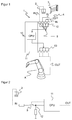
- FIG. 1 shows a schematic representation of a technical automation system 1, which has a robot arm as an actuator A for performing automated processes.
- the actuator A is monitored by means of at least one signal generator 2, 3, 4 in the performance of its work.
- the signal generator 2, 3, 4 is an optoelectronic sensor, an emergency stop switch or the like.
- the actuator A is monitored by a camera 2, a light grid 3 and an emergency stop switch 4.
- the signal generator 2, 3, 4 and the actuator A are connected to each other via a safety controller 10 for safe operation of the technical system 1, wherein the signal generator 2, 3, 4 with at least one input unit 12 of the safety controller 10 and the actuator A with at least one output unit 13 of the safety controller 10 is connected.
- the input unit 12 of the safety controller 10 is provided for receiving a signal IN from the connected signal generator 2, 3, 4 of the technical system 1.
- the output unit 13 is provided for transmitting a generated control command OUT to the connected actuator A of the technical system 1.
- the safety controller 10 here comprises a control unit 11 which is provided for reading in the signal IN received by the input unit 12 and for generating the control command OUT sent out to the actuator A.
- the technical system 1 is safely operated in accordance with the safety standards EN ISO 13849-1, IEC 62061 or the like by the safety controller 10 by the signal generator 2, 3, 4 safety-related signals IN respect.
- the safety-related signals In are forwarded by the input unit 12 of the safety controller 10 to the control unit 11 of the safety controller 10, so that the control unit 11 of the safety controller 10 generates corresponding control commands OUT and sends them to the output unit 13 of the safety controller 10.
- the output unit 13 of the safety controller 10 sends the control commands OUT to the actuator A of the technical system 1, so that it moves according to the control commands OUT.
- the input unit 12 on the input side, a switching element 5, so that the signal generator 2, 3, 4 is connected via the switching element 5 to the input unit 12.
- the switching element 5 can be controlled by the control unit 11 of the safety controller 10.
- FIG. 2 A schematic detail of such an inventive embodiment of the input of the safety controller 10 is in the FIG. 2 shown.
- the signal transmitter in the form of the camera 2 is connected to the switching element 5, which is arranged on the input side of the input unit 12 of the safety controller 10 and by means of the input unit 12 of the safety controller 10 the control unit 11 is connected.
- the switching element 5 is an electronic or an electromechanical switch, which can be controlled by the control unit 11 of the safety controller 10.
- the signal transmitter or the camera 2 sends the detected signal IN to the input unit 12 of the safety controller 10.
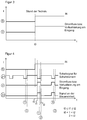
- the signal IN of the signal generator 2 as shown in the curve S, from a time t0 causes a current flow or a power loss, as shown in the curve V, at the input unit 12 of the safety controller 10, since this acts as a current sink.
- the power loss remains as long as the time t0 exist as the signal IN of the signal generator 2, 3, 4 at the input of the safety controller 10 is applied.
- FIG. 4 a temporal representation of the operation of the safety controller 10 according to the invention with the switching element 5 of the input unit 12 is shown.
- the intensity of the signal IN of the signal generator 2, 3, 4 is again shown, wherein the intensity changes from a value of zero to a value not equal to zero from the time t0. That From time t0, the signal generator 2, 3, 4 of the input unit 12 of the safety controller 10 provides a signal.
- the control of the control unit 11 of the safety controller 10 is shown to the switching element 5 of the input unit 12, wherein the switching element 5 periodically, in particular at discrete-time intervals, is controlled by the control unit 11 of the safety controller 10 and is controlled.
- the switching element 5 of the input unit 12 as shown in the curve Z1, repeatedly operated by the control unit 11 of the safety controller 10 by a switching signal.
- switching element 5 of the input unit 12 is or can be actuated, in particular closable, or actuated, in particular closed, curve Z2 at the time t1 immediately before reading in the signal IN received and made available by the signal generator 2, 3, 4 ,
- control unit 11 of the safety controller 10 again the switching element 5 of the input unit 12, so that the connection between the signal generator 2, 3, 4 and the input unit 12 is interrupted or - Curve Z1 at time t2.
- the power loss saved advantageously makes energy available, so that the switching of the switching element 5 of the input unit 12 can be carried out with higher currents or higher current values without additional consumption. This additionally allows the advantage of improved immunity to interference or robustness of the input unit 12.
- the control unit 11 of the safety controller 10 starts reading the signal IN of the signal generator 2, 3, 4.
- the signal IN read in at this time (1) is processed by the control unit 11, so that a control command OUT can be generated and sent to the actuator A via the output unit 13.
- the control unit 11 After the re-operation, in particular the opening, of the switching element 5 of the input unit 12 at the time t2, the control unit 11 is formed, at the time (2) a signal level, a status pin or the like of the connection between the signal generator 2, 3, 4 and the Input unit 12 of the safety controller 10 read. In this case, it is determined by the control unit 11 based on the signal level, the status pin or the like, whether the connection between the signal generator 2, 3, 4 and the input unit 12 of the safety controller 10 or the switching element 5 of the input unit 12 is error-free.
- control unit 11 determines by means of the curve V of the current flow or the power loss or the curve Z2, whether the signal level, the status pin or the like has changed or not by the actuation of the switching element 5.
Landscapes
- Physics & Mathematics (AREA)
- General Physics & Mathematics (AREA)
- Engineering & Computer Science (AREA)
- Automation & Control Theory (AREA)
- Safety Devices In Control Systems (AREA)
Claims (4)
- Dispositif de commande de sécurité (10) destiné au fonctionnement sécurisé d'une installation technique (1), comportant au moins une unité d'entrée (12) destinée à recevoir un signal (IN) d'au moins un émetteur de signal connecté (2, 3, 4) de l'installation technique (1), une unité de commande (11) destinée à lire le signal reçu (IN) et à générer un ordre de commande (OUT), et au moins une unité de sortie (13) destinée à envoyer l'ordre de commande généré (OUT) à au moins un actionneur connecté (A) de l'installation technique (1),
caractérisé en ce que
l'unité d'entrée (12) comprend du côté entrée un élément de commutation (5) qui est pilotable par l'unité de commande (11) et réalisé de telle sorte que l'élément de commutation (5) est pilotable périodiquement, en particulier à des intervalles temporels discret, par l'unité de commande (11) et est susceptible d'être actionné, en particulier fermé, par l'unité de commande (11) directement avant de lire le signal reçu (IN), et est susceptible d'être ré-actionné, en particulier ouvert, par l'unité de commande (11) après avoir lu le signal reçu (IN),
l'unité de commande (11) étant réalisée pour déterminer un état de l'unité d'entrée (12) à partir d'un actionnement, en particulier d'une fermeture et d'une ouverture de l'élément de commutation (5). - Dispositif de commande de sécurité (10) selon la revendication 1, caractérisé en ce que l'élément de commutation (5) est un commutateur électronique ou électromécanique.
- Procédé pour faire fonctionner un dispositif de commande de sécurité (10) comportant au moins une unité d'entrée (12) destinée à recevoir un signal (IN) d'au moins un émetteur de signal connecté (2, 3, 4) d'une installation technique (1), une unité de commande (11) destinée à lire le signal reçu (IN) et à générer un ordre de commande (OUT), et au moins une unité de sortie (13) destinée à envoyer l'ordre de commande généré (OUT) à au moins un actionneur connecté (A) de l'installation technique (1), le signal (IN) de l'émetteur de signal (2, 3, 4) étant envoyé à l'unité d'entrée (12), caractérisé en ce que l'unité de commande (11) actionne, en particulier ferme ou ouvre, périodiquement, en particulier à des intervalles temporels discrets, un élément de commutation (5) agencé sur un côté entrée de l'unité d'entrée (12), de sorte que le signal (IN) est lu, et ensuite elle réactionne, en particulier ouvre, l'élément de commutation (5), de sorte que l'unité d'entrée (12) est séparée de l'émetteur de signal (2, 3, 4),
dans lequel l'unité de commande (11) compare un état de l'élément de commutation (5) lors de la fermeture et de l'ouverture et en détermine une disponibilité au fonctionnement sûre sans erreur de l'élément de commutation (5) et de l'unité d'entrée (12). - Procédé selon la revendication 3, caractérisé en ce qu'après la mise en marche ou la coupure de l'élément d'actionnement (5) l'unité de commande (11) détermine une erreur de l'élément de commutation (5) ou de l'unité d'entrée (12) lorsqu'un niveau de signal, un code d'état ou similaire de l'élément de commutation (5) ou de l'unité d'entrée (12) reste inchangé.
Priority Applications (3)
| Application Number | Priority Date | Filing Date | Title |
|---|---|---|---|
| EP14166081.1A EP2937745B1 (fr) | 2014-04-25 | 2014-04-25 | Commande de sécurité destinée au fonctionnement sécurisé d'une installation technique et procédé de fonctionnement de la commande de sécurité |
| US14/679,591 US10114345B2 (en) | 2014-04-25 | 2015-04-06 | Safety control for the secure operation of a technical plant and method of operating a safety control |
| CN201510162186.5A CN105045088A (zh) | 2014-04-25 | 2015-04-08 | 用于安全操作技术设备的安全控制装置及其操作方法 |
Applications Claiming Priority (1)
| Application Number | Priority Date | Filing Date | Title |
|---|---|---|---|
| EP14166081.1A EP2937745B1 (fr) | 2014-04-25 | 2014-04-25 | Commande de sécurité destinée au fonctionnement sécurisé d'une installation technique et procédé de fonctionnement de la commande de sécurité |
Publications (2)
| Publication Number | Publication Date |
|---|---|
| EP2937745A1 EP2937745A1 (fr) | 2015-10-28 |
| EP2937745B1 true EP2937745B1 (fr) | 2016-10-05 |
Family
ID=50555081
Family Applications (1)
| Application Number | Title | Priority Date | Filing Date |
|---|---|---|---|
| EP14166081.1A Revoked EP2937745B1 (fr) | 2014-04-25 | 2014-04-25 | Commande de sécurité destinée au fonctionnement sécurisé d'une installation technique et procédé de fonctionnement de la commande de sécurité |
Country Status (3)
| Country | Link |
|---|---|
| US (1) | US10114345B2 (fr) |
| EP (1) | EP2937745B1 (fr) |
| CN (1) | CN105045088A (fr) |
Families Citing this family (2)
| Publication number | Priority date | Publication date | Assignee | Title |
|---|---|---|---|---|
| DE112016007002T5 (de) * | 2016-06-22 | 2019-03-07 | Mitsubishi Electric Corporation | Funkkommunikationsvorrichtung, Funkstationsvorrichtung, Instrumentensteuerverfahren und Instrumentensteuerprogramm |
| DE102021106584B4 (de) * | 2021-03-18 | 2024-02-22 | Sick Ag | System mit mindestens einem Anlagesystem mit mindestens mehreren Anlageteilen |
Family Cites Families (24)
| Publication number | Priority date | Publication date | Assignee | Title |
|---|---|---|---|---|
| US4370718A (en) * | 1979-02-06 | 1983-01-25 | Chasek Norman E | Responsive traffic light control system and method based on conservation of aggregate momentum |
| GB2251991A (en) * | 1991-01-18 | 1992-07-22 | Nnc Ltd | Electrical safety system for de-energising a load in response to a plurality of simultaneous fault conditions |
| US6172432B1 (en) * | 1999-06-18 | 2001-01-09 | Gen-Tran Corporation | Automatic transfer switch |
| DE19939567B4 (de) * | 1999-08-20 | 2007-07-19 | Pilz Gmbh & Co. Kg | Vorrichtung zum Steuern von sicherheitskritischen Prozessen |
| WO2001018932A1 (fr) * | 1999-09-10 | 2001-03-15 | Intra International Ab | Systeme de gestion d'alimentation intelligent |
| WO2002007365A2 (fr) * | 2000-07-13 | 2002-01-24 | Nxegen | Systeme et procede permettant de surveiller et de commander l'utilisation d'energie |
| DE60107529D1 (de) * | 2001-01-12 | 2005-01-05 | St Microelectronics Srl | Chaotische Signale verwendendes Kommunikationsverfahren |
| DE10107107A1 (de) * | 2001-02-14 | 2002-08-29 | Putzmeister Ag | Vorrichtung zur Betätigung eines Knickmasts eines Großmanipulators sowie Großmanipulator mit einer solchen Vorrichtung |
| JP2003216231A (ja) * | 2002-01-18 | 2003-07-31 | Hitachi Ltd | 現場監視・操作装置 |
| US7076311B2 (en) * | 2002-07-09 | 2006-07-11 | Rockwell Automation Technologies, Inc. | Configurable safety system for implementation on industrial system and method of implementing same |
| US20040075343A1 (en) * | 2002-09-05 | 2004-04-22 | Paul Wareham | System and method for power load management |
| US7865251B2 (en) * | 2003-01-28 | 2011-01-04 | Fisher-Rosemount Systems, Inc. | Method for intercontroller communications in a safety instrumented system or a process control system |
| DE10320522A1 (de) | 2003-05-02 | 2004-11-25 | Pilz Gmbh & Co. | Verfahren und Vorrichtug zum Steuern eines sicherheitskritischen Prozesses |
| JP4212970B2 (ja) * | 2003-06-30 | 2009-01-21 | 株式会社キーエンス | 安全リレーシステム |
| WO2005096465A1 (fr) * | 2004-04-01 | 2005-10-13 | System Consult Pty Ltd | Module de commutation de securite |
| US7149655B2 (en) * | 2004-06-18 | 2006-12-12 | General Electric Company | Methods and apparatus for safety controls in industrial processes |
| US7378749B2 (en) * | 2005-10-26 | 2008-05-27 | Moore Donald O | Electrical generator system |
| DE102006032955A1 (de) * | 2006-07-17 | 2008-02-07 | Siemens Ag | Industrieanlage mit einem sicherheitsrelevanten Bereich |
| JP4671131B2 (ja) * | 2006-08-10 | 2011-04-13 | 横河電機株式会社 | 安全計装システム |
| DE102006052739A1 (de) * | 2006-11-08 | 2008-05-15 | BSH Bosch und Siemens Hausgeräte GmbH | Verfahren und Schaltungsanordnung zur sicheren Ansteuerung von Aktoren, Sensoren und/oder Verbrauchern in einem diese enthaltenden elektrischen Gerät, insbesondere in einem elektrischen Hausgerät |
| US7551028B1 (en) * | 2006-12-11 | 2009-06-23 | Marvell International Ltd. | Signal generators for current-mode three-level digital amplifiers |
| US7777579B2 (en) * | 2006-12-29 | 2010-08-17 | Broadcom Corporation | Local oscillation generator with mixer having reduced signal power consumption |
| JP2010242737A (ja) * | 2008-05-12 | 2010-10-28 | Rusk Intellectual Reserve Ag | エネルギ効率の高い自動車 |
| US9218233B2 (en) * | 2012-07-24 | 2015-12-22 | Paul Venditti | Systems and methods for control reliability operations |
-
2014
- 2014-04-25 EP EP14166081.1A patent/EP2937745B1/fr not_active Revoked
-
2015
- 2015-04-06 US US14/679,591 patent/US10114345B2/en active Active
- 2015-04-08 CN CN201510162186.5A patent/CN105045088A/zh active Pending
Non-Patent Citations (4)
| Title |
|---|
| "Automation Technology", WIELAND ELECTRISCHE VERBINDUNGEN, May 2005 (2005-05-01), pages 1 - 11, XP055397069 |
| "DIN EN 61508-7:2001", DIN EN 61508-7:2001, 2001, pages 15 - 16, 18, 23, XP055397076 |
| "Funktionale Sicherheit von Maschinensteuerungen - Anwendung der DIN EN ISO 13849 (BGIA Report)", DEUTSCHE GESETZLICHE UNFALLVERSICHERUNG, February 2008 (2008-02-01), pages 1 - 259, XP055397260 |
| "Handbuch", WIELAND ELECTRISCHE VERBINDUNGEN, December 2005 (2005-12-01), pages 1 - 72, XP055397060 |
Also Published As
| Publication number | Publication date |
|---|---|
| US10114345B2 (en) | 2018-10-30 |
| EP2937745A1 (fr) | 2015-10-28 |
| US20150309481A1 (en) | 2015-10-29 |
| CN105045088A (zh) | 2015-11-11 |
Similar Documents
| Publication | Publication Date | Title |
|---|---|---|
| EP0742499B1 (fr) | Traitement fiable de signaux orientés sûreté | |
| EP3069202B2 (fr) | Commande de sécurité à entrées configurables | |
| DE102011002481A1 (de) | Steuerungssystem | |
| DE102012103015B4 (de) | Sicherheitsschaltvorrichtung mit Schaltelement im Hilfskontaktstrompfad | |
| WO2005101439A1 (fr) | Appareil de signalisation pour circuit de protection | |
| EP2246756B1 (fr) | Procédé et appareil de commande destinés à commander un composant d'automatisation industriel lié à la sécurité | |
| DE112008003195T5 (de) | Elektrischer Schaltkreis mit einem physikalischen Übertragungsschicht-Diagnosesystem | |
| EP2937745B1 (fr) | Commande de sécurité destinée au fonctionnement sécurisé d'une installation technique et procédé de fonctionnement de la commande de sécurité | |
| EP2853929A1 (fr) | Capteur de sécurité opto-électronique | |
| EP3470939B1 (fr) | Procédé et système de surveillance de l'intégrité de sécurité d'une fonction de sécurité fournie par un système de sécurité | |
| EP3470937B1 (fr) | Procédé et dispositifs de surveillance du temps réactionnel d'une fonction de sécurité fournie par un système de sécurité | |
| EP4146576B1 (fr) | Procédé de fonctionnement d'une installation de transport de personnes par configuration fiable d'un dispositif de sécurité électronique | |
| EP0120339A1 (fr) | Dispositif pour une commande fiable d'un processus | |
| EP2013731B1 (fr) | Agencement de circuit et procédé permettant de faire fonctionner un agencement de circuit | |
| DE202014101970U1 (de) | Sicherheitssteuerung zum sicheren Betreiben einer technischen Anlage | |
| EP4321949A1 (fr) | Dispositif de commande modulaire | |
| EP3588216B1 (fr) | Procédé et système de fourniture protégée contre les erreurs d'une valeur de sortie analogique | |
| AT521134B1 (de) | Industrieanlage | |
| EP3644143B1 (fr) | Ensemble périphérique à paramétrage automatique | |
| DE102005007477B4 (de) | Programmierbare Steuerung zur Maschinen-und/oder Anlagenautomatisierung mit Standard-Steuerungs- und Sicherheitsfunktionen und Kommunikation mit einer Sicherheits-EA sowie Verfahren zum Betrieb der programmierbaren Steuerung | |
| EP3048498B1 (fr) | Procédé de lecture de données de diagnostic provenant d'une commande de sécurité | |
| DD274072A1 (de) | Schaltungsanordnung fuer eine pressensicherheitssteuerung | |
| EP2482154A1 (fr) | Procédé et appareil de commande destinés à commander un composant d'automatisation industriel orienté vers la protection | |
| EP3026514B1 (fr) | Installation d'automatisation et procédé de commande externe d'un algorithme d'autocontrôle dans un dispositif de sécurité décentralisé | |
| EP2950174A1 (fr) | Méthode et appareil pour surveiller en toute sécurité l'état de deux dispositifs |
Legal Events
| Date | Code | Title | Description |
|---|---|---|---|
| PUAI | Public reference made under article 153(3) epc to a published international application that has entered the european phase |
Free format text: ORIGINAL CODE: 0009012 |
|
| 17P | Request for examination filed |
Effective date: 20141219 |
|
| AK | Designated contracting states |
Kind code of ref document: A1 Designated state(s): AL AT BE BG CH CY CZ DE DK EE ES FI FR GB GR HR HU IE IS IT LI LT LU LV MC MK MT NL NO PL PT RO RS SE SI SK SM TR |
|
| AX | Request for extension of the european patent |
Extension state: BA ME |
|
| 17Q | First examination report despatched |
Effective date: 20151218 |
|
| GRAP | Despatch of communication of intention to grant a patent |
Free format text: ORIGINAL CODE: EPIDOSNIGR1 |
|
| INTG | Intention to grant announced |
Effective date: 20160628 |
|
| GRAS | Grant fee paid |
Free format text: ORIGINAL CODE: EPIDOSNIGR3 |
|
| GRAA | (expected) grant |
Free format text: ORIGINAL CODE: 0009210 |
|
| AK | Designated contracting states |
Kind code of ref document: B1 Designated state(s): AL AT BE BG CH CY CZ DE DK EE ES FI FR GB GR HR HU IE IS IT LI LT LU LV MC MK MT NL NO PL PT RO RS SE SI SK SM TR |
|
| REG | Reference to a national code |
Ref country code: GB Ref legal event code: FG4D Free format text: NOT ENGLISH |
|
| REG | Reference to a national code |
Ref country code: CH Ref legal event code: EP |
|
| REG | Reference to a national code |
Ref country code: AT Ref legal event code: REF Ref document number: 835135 Country of ref document: AT Kind code of ref document: T Effective date: 20161015 |
|
| REG | Reference to a national code |
Ref country code: IE Ref legal event code: FG4D Free format text: LANGUAGE OF EP DOCUMENT: GERMAN |
|
| REG | Reference to a national code |
Ref country code: DE Ref legal event code: R096 Ref document number: 502014001622 Country of ref document: DE |
|
| REG | Reference to a national code |
Ref country code: NL Ref legal event code: MP Effective date: 20161005 |
|
| REG | Reference to a national code |
Ref country code: LT Ref legal event code: MG4D |
|
| PG25 | Lapsed in a contracting state [announced via postgrant information from national office to epo] |
Ref country code: LV Free format text: LAPSE BECAUSE OF FAILURE TO SUBMIT A TRANSLATION OF THE DESCRIPTION OR TO PAY THE FEE WITHIN THE PRESCRIBED TIME-LIMIT Effective date: 20161005 |
|
| REG | Reference to a national code |
Ref country code: FR Ref legal event code: PLFP Year of fee payment: 4 |
|
| PG25 | Lapsed in a contracting state [announced via postgrant information from national office to epo] |
Ref country code: GR Free format text: LAPSE BECAUSE OF FAILURE TO SUBMIT A TRANSLATION OF THE DESCRIPTION OR TO PAY THE FEE WITHIN THE PRESCRIBED TIME-LIMIT Effective date: 20170106 Ref country code: NO Free format text: LAPSE BECAUSE OF FAILURE TO SUBMIT A TRANSLATION OF THE DESCRIPTION OR TO PAY THE FEE WITHIN THE PRESCRIBED TIME-LIMIT Effective date: 20170105 Ref country code: SE Free format text: LAPSE BECAUSE OF FAILURE TO SUBMIT A TRANSLATION OF THE DESCRIPTION OR TO PAY THE FEE WITHIN THE PRESCRIBED TIME-LIMIT Effective date: 20161005 Ref country code: LT Free format text: LAPSE BECAUSE OF FAILURE TO SUBMIT A TRANSLATION OF THE DESCRIPTION OR TO PAY THE FEE WITHIN THE PRESCRIBED TIME-LIMIT Effective date: 20161005 |
|
| PG25 | Lapsed in a contracting state [announced via postgrant information from national office to epo] |
Ref country code: NL Free format text: LAPSE BECAUSE OF FAILURE TO SUBMIT A TRANSLATION OF THE DESCRIPTION OR TO PAY THE FEE WITHIN THE PRESCRIBED TIME-LIMIT Effective date: 20161005 Ref country code: FI Free format text: LAPSE BECAUSE OF FAILURE TO SUBMIT A TRANSLATION OF THE DESCRIPTION OR TO PAY THE FEE WITHIN THE PRESCRIBED TIME-LIMIT Effective date: 20161005 Ref country code: IS Free format text: LAPSE BECAUSE OF FAILURE TO SUBMIT A TRANSLATION OF THE DESCRIPTION OR TO PAY THE FEE WITHIN THE PRESCRIBED TIME-LIMIT Effective date: 20170205 Ref country code: ES Free format text: LAPSE BECAUSE OF FAILURE TO SUBMIT A TRANSLATION OF THE DESCRIPTION OR TO PAY THE FEE WITHIN THE PRESCRIBED TIME-LIMIT Effective date: 20161005 Ref country code: HR Free format text: LAPSE BECAUSE OF FAILURE TO SUBMIT A TRANSLATION OF THE DESCRIPTION OR TO PAY THE FEE WITHIN THE PRESCRIBED TIME-LIMIT Effective date: 20161005 Ref country code: PL Free format text: LAPSE BECAUSE OF FAILURE TO SUBMIT A TRANSLATION OF THE DESCRIPTION OR TO PAY THE FEE WITHIN THE PRESCRIBED TIME-LIMIT Effective date: 20161005 Ref country code: PT Free format text: LAPSE BECAUSE OF FAILURE TO SUBMIT A TRANSLATION OF THE DESCRIPTION OR TO PAY THE FEE WITHIN THE PRESCRIBED TIME-LIMIT Effective date: 20170206 Ref country code: RS Free format text: LAPSE BECAUSE OF FAILURE TO SUBMIT A TRANSLATION OF THE DESCRIPTION OR TO PAY THE FEE WITHIN THE PRESCRIBED TIME-LIMIT Effective date: 20161005 |
|
| REG | Reference to a national code |
Ref country code: DE Ref legal event code: R026 Ref document number: 502014001622 Country of ref document: DE |
|
| PLBI | Opposition filed |
Free format text: ORIGINAL CODE: 0009260 |
|
| PG25 | Lapsed in a contracting state [announced via postgrant information from national office to epo] |
Ref country code: DK Free format text: LAPSE BECAUSE OF FAILURE TO SUBMIT A TRANSLATION OF THE DESCRIPTION OR TO PAY THE FEE WITHIN THE PRESCRIBED TIME-LIMIT Effective date: 20161005 Ref country code: EE Free format text: LAPSE BECAUSE OF FAILURE TO SUBMIT A TRANSLATION OF THE DESCRIPTION OR TO PAY THE FEE WITHIN THE PRESCRIBED TIME-LIMIT Effective date: 20161005 Ref country code: SK Free format text: LAPSE BECAUSE OF FAILURE TO SUBMIT A TRANSLATION OF THE DESCRIPTION OR TO PAY THE FEE WITHIN THE PRESCRIBED TIME-LIMIT Effective date: 20161005 Ref country code: RO Free format text: LAPSE BECAUSE OF FAILURE TO SUBMIT A TRANSLATION OF THE DESCRIPTION OR TO PAY THE FEE WITHIN THE PRESCRIBED TIME-LIMIT Effective date: 20161005 Ref country code: CZ Free format text: LAPSE BECAUSE OF FAILURE TO SUBMIT A TRANSLATION OF THE DESCRIPTION OR TO PAY THE FEE WITHIN THE PRESCRIBED TIME-LIMIT Effective date: 20161005 |
|
| 26 | Opposition filed |
Opponent name: WIELAND ELECTRIC GMBH Effective date: 20170704 |
|
| PLAX | Notice of opposition and request to file observation + time limit sent |
Free format text: ORIGINAL CODE: EPIDOSNOBS2 |
|
| PG25 | Lapsed in a contracting state [announced via postgrant information from national office to epo] |
Ref country code: BG Free format text: LAPSE BECAUSE OF FAILURE TO SUBMIT A TRANSLATION OF THE DESCRIPTION OR TO PAY THE FEE WITHIN THE PRESCRIBED TIME-LIMIT Effective date: 20170105 Ref country code: SM Free format text: LAPSE BECAUSE OF FAILURE TO SUBMIT A TRANSLATION OF THE DESCRIPTION OR TO PAY THE FEE WITHIN THE PRESCRIBED TIME-LIMIT Effective date: 20161005 Ref country code: IT Free format text: LAPSE BECAUSE OF FAILURE TO SUBMIT A TRANSLATION OF THE DESCRIPTION OR TO PAY THE FEE WITHIN THE PRESCRIBED TIME-LIMIT Effective date: 20161005 |
|
| PLBB | Reply of patent proprietor to notice(s) of opposition received |
Free format text: ORIGINAL CODE: EPIDOSNOBS3 |
|
| PG25 | Lapsed in a contracting state [announced via postgrant information from national office to epo] |
Ref country code: SI Free format text: LAPSE BECAUSE OF FAILURE TO SUBMIT A TRANSLATION OF THE DESCRIPTION OR TO PAY THE FEE WITHIN THE PRESCRIBED TIME-LIMIT Effective date: 20161005 |
|
| REG | Reference to a national code |
Ref country code: CH Ref legal event code: PL |
|
| PLAB | Opposition data, opponent's data or that of the opponent's representative modified |
Free format text: ORIGINAL CODE: 0009299OPPO |
|
| REG | Reference to a national code |
Ref country code: IE Ref legal event code: MM4A |
|
| PG25 | Lapsed in a contracting state [announced via postgrant information from national office to epo] |
Ref country code: MC Free format text: LAPSE BECAUSE OF FAILURE TO SUBMIT A TRANSLATION OF THE DESCRIPTION OR TO PAY THE FEE WITHIN THE PRESCRIBED TIME-LIMIT Effective date: 20161005 |
|
| R26 | Opposition filed (corrected) |
Opponent name: WIELAND ELECTRIC GMBH Effective date: 20170704 |
|
| PG25 | Lapsed in a contracting state [announced via postgrant information from national office to epo] |
Ref country code: LI Free format text: LAPSE BECAUSE OF NON-PAYMENT OF DUE FEES Effective date: 20170430 Ref country code: LU Free format text: LAPSE BECAUSE OF NON-PAYMENT OF DUE FEES Effective date: 20170425 Ref country code: CH Free format text: LAPSE BECAUSE OF NON-PAYMENT OF DUE FEES Effective date: 20170430 |
|
| REG | Reference to a national code |
Ref country code: BE Ref legal event code: MM Effective date: 20170430 |
|
| REG | Reference to a national code |
Ref country code: FR Ref legal event code: PLFP Year of fee payment: 5 |
|
| PG25 | Lapsed in a contracting state [announced via postgrant information from national office to epo] |
Ref country code: IE Free format text: LAPSE BECAUSE OF NON-PAYMENT OF DUE FEES Effective date: 20170425 |
|
| PG25 | Lapsed in a contracting state [announced via postgrant information from national office to epo] |
Ref country code: BE Free format text: LAPSE BECAUSE OF NON-PAYMENT OF DUE FEES Effective date: 20170430 |
|
| PGFP | Annual fee paid to national office [announced via postgrant information from national office to epo] |
Ref country code: DE Payment date: 20180423 Year of fee payment: 5 |
|
| PGFP | Annual fee paid to national office [announced via postgrant information from national office to epo] |
Ref country code: FR Payment date: 20180424 Year of fee payment: 5 |
|
| PG25 | Lapsed in a contracting state [announced via postgrant information from national office to epo] |
Ref country code: MT Free format text: LAPSE BECAUSE OF FAILURE TO SUBMIT A TRANSLATION OF THE DESCRIPTION OR TO PAY THE FEE WITHIN THE PRESCRIBED TIME-LIMIT Effective date: 20161005 |
|
| REG | Reference to a national code |
Ref country code: DE Ref legal event code: R064 Ref document number: 502014001622 Country of ref document: DE Ref country code: DE Ref legal event code: R103 Ref document number: 502014001622 Country of ref document: DE |
|
| PGFP | Annual fee paid to national office [announced via postgrant information from national office to epo] |
Ref country code: GB Payment date: 20180424 Year of fee payment: 5 |
|
| RDAF | Communication despatched that patent is revoked |
Free format text: ORIGINAL CODE: EPIDOSNREV1 |
|
| STAA | Information on the status of an ep patent application or granted ep patent |
Free format text: STATUS: THE PATENT HAS BEEN GRANTED |
|
| RDAG | Patent revoked |
Free format text: ORIGINAL CODE: 0009271 |
|
| STAA | Information on the status of an ep patent application or granted ep patent |
Free format text: STATUS: PATENT REVOKED |
|
| 27W | Patent revoked |
Effective date: 20181025 |
|
| GBPR | Gb: patent revoked under art. 102 of the ep convention designating the uk as contracting state |
Effective date: 20181025 |
|
| REG | Reference to a national code |
Ref country code: AT Ref legal event code: MA03 Ref document number: 835135 Country of ref document: AT Kind code of ref document: T Effective date: 20181025 |
|
| PG25 | Lapsed in a contracting state [announced via postgrant information from national office to epo] |
Ref country code: MK Free format text: LAPSE BECAUSE OF FAILURE TO SUBMIT A TRANSLATION OF THE DESCRIPTION OR TO PAY THE FEE WITHIN THE PRESCRIBED TIME-LIMIT Effective date: 20161005 |
|
| PG25 | Lapsed in a contracting state [announced via postgrant information from national office to epo] |
Ref country code: CY Free format text: LAPSE BECAUSE OF FAILURE TO SUBMIT A TRANSLATION OF THE DESCRIPTION OR TO PAY THE FEE WITHIN THE PRESCRIBED TIME-LIMIT Effective date: 20161005 |
|
| PG25 | Lapsed in a contracting state [announced via postgrant information from national office to epo] |
Ref country code: AL Free format text: LAPSE BECAUSE OF FAILURE TO SUBMIT A TRANSLATION OF THE DESCRIPTION OR TO PAY THE FEE WITHIN THE PRESCRIBED TIME-LIMIT Effective date: 20161005 |
|
| PG25 | Lapsed in a contracting state [announced via postgrant information from national office to epo] |
Ref country code: TR Free format text: LAPSE BECAUSE OF FAILURE TO SUBMIT A TRANSLATION OF THE DESCRIPTION OR TO PAY THE FEE WITHIN THE PRESCRIBED TIME-LIMIT Effective date: 20161005 |