EP2937916B1 - Module de batterie comprenant des éléments de connexion comprenant des métaux dissemblables - Google Patents
Module de batterie comprenant des éléments de connexion comprenant des métaux dissemblables Download PDFInfo
- Publication number
- EP2937916B1 EP2937916B1 EP14819878.1A EP14819878A EP2937916B1 EP 2937916 B1 EP2937916 B1 EP 2937916B1 EP 14819878 A EP14819878 A EP 14819878A EP 2937916 B1 EP2937916 B1 EP 2937916B1
- Authority
- EP
- European Patent Office
- Prior art keywords
- connecting part
- electrode terminal
- buried
- welding
- battery module
- Prior art date
- Legal status (The legal status is an assumption and is not a legal conclusion. Google has not performed a legal analysis and makes no representation as to the accuracy of the status listed.)
- Active
Links
Images

Classifications
-
- H—ELECTRICITY
- H01—ELECTRIC ELEMENTS
- H01M—PROCESSES OR MEANS, e.g. BATTERIES, FOR THE DIRECT CONVERSION OF CHEMICAL ENERGY INTO ELECTRICAL ENERGY
- H01M50/00—Constructional details or processes of manufacture of the non-active parts of electrochemical cells other than fuel cells, e.g. hybrid cells
- H01M50/50—Current conducting connections for cells or batteries
- H01M50/543—Terminals
-
- H—ELECTRICITY
- H01—ELECTRIC ELEMENTS
- H01M—PROCESSES OR MEANS, e.g. BATTERIES, FOR THE DIRECT CONVERSION OF CHEMICAL ENERGY INTO ELECTRICAL ENERGY
- H01M50/00—Constructional details or processes of manufacture of the non-active parts of electrochemical cells other than fuel cells, e.g. hybrid cells
- H01M50/10—Primary casings; Jackets or wrappings
- H01M50/116—Primary casings; Jackets or wrappings characterised by the material
- H01M50/124—Primary casings; Jackets or wrappings characterised by the material having a layered structure
-
- H—ELECTRICITY
- H01—ELECTRIC ELEMENTS
- H01M—PROCESSES OR MEANS, e.g. BATTERIES, FOR THE DIRECT CONVERSION OF CHEMICAL ENERGY INTO ELECTRICAL ENERGY
- H01M50/00—Constructional details or processes of manufacture of the non-active parts of electrochemical cells other than fuel cells, e.g. hybrid cells
- H01M50/10—Primary casings; Jackets or wrappings
- H01M50/116—Primary casings; Jackets or wrappings characterised by the material
- H01M50/117—Inorganic material
- H01M50/119—Metals
-
- H—ELECTRICITY
- H01—ELECTRIC ELEMENTS
- H01M—PROCESSES OR MEANS, e.g. BATTERIES, FOR THE DIRECT CONVERSION OF CHEMICAL ENERGY INTO ELECTRICAL ENERGY
- H01M50/00—Constructional details or processes of manufacture of the non-active parts of electrochemical cells other than fuel cells, e.g. hybrid cells
- H01M50/10—Primary casings; Jackets or wrappings
- H01M50/116—Primary casings; Jackets or wrappings characterised by the material
- H01M50/121—Organic material
-
- H—ELECTRICITY
- H01—ELECTRIC ELEMENTS
- H01M—PROCESSES OR MEANS, e.g. BATTERIES, FOR THE DIRECT CONVERSION OF CHEMICAL ENERGY INTO ELECTRICAL ENERGY
- H01M50/00—Constructional details or processes of manufacture of the non-active parts of electrochemical cells other than fuel cells, e.g. hybrid cells
- H01M50/10—Primary casings; Jackets or wrappings
- H01M50/172—Arrangements of electric connectors penetrating the casing
- H01M50/174—Arrangements of electric connectors penetrating the casing adapted for the shape of the cells
- H01M50/178—Arrangements of electric connectors penetrating the casing adapted for the shape of the cells for pouch or flexible bag cells
-
- H—ELECTRICITY
- H01—ELECTRIC ELEMENTS
- H01M—PROCESSES OR MEANS, e.g. BATTERIES, FOR THE DIRECT CONVERSION OF CHEMICAL ENERGY INTO ELECTRICAL ENERGY
- H01M50/00—Constructional details or processes of manufacture of the non-active parts of electrochemical cells other than fuel cells, e.g. hybrid cells
- H01M50/50—Current conducting connections for cells or batteries
- H01M50/502—Interconnectors for connecting terminals of adjacent batteries; Interconnectors for connecting cells outside a battery casing
- H01M50/503—Interconnectors for connecting terminals of adjacent batteries; Interconnectors for connecting cells outside a battery casing characterised by the shape of the interconnectors
-
- H—ELECTRICITY
- H01—ELECTRIC ELEMENTS
- H01M—PROCESSES OR MEANS, e.g. BATTERIES, FOR THE DIRECT CONVERSION OF CHEMICAL ENERGY INTO ELECTRICAL ENERGY
- H01M50/00—Constructional details or processes of manufacture of the non-active parts of electrochemical cells other than fuel cells, e.g. hybrid cells
- H01M50/50—Current conducting connections for cells or batteries
- H01M50/502—Interconnectors for connecting terminals of adjacent batteries; Interconnectors for connecting cells outside a battery casing
- H01M50/514—Methods for interconnecting adjacent batteries or cells
- H01M50/516—Methods for interconnecting adjacent batteries or cells by welding, soldering or brazing
-
- H—ELECTRICITY
- H01—ELECTRIC ELEMENTS
- H01M—PROCESSES OR MEANS, e.g. BATTERIES, FOR THE DIRECT CONVERSION OF CHEMICAL ENERGY INTO ELECTRICAL ENERGY
- H01M50/00—Constructional details or processes of manufacture of the non-active parts of electrochemical cells other than fuel cells, e.g. hybrid cells
- H01M50/50—Current conducting connections for cells or batteries
- H01M50/502—Interconnectors for connecting terminals of adjacent batteries; Interconnectors for connecting cells outside a battery casing
- H01M50/521—Interconnectors for connecting terminals of adjacent batteries; Interconnectors for connecting cells outside a battery casing characterised by the material
- H01M50/522—Inorganic material
-
- H—ELECTRICITY
- H01—ELECTRIC ELEMENTS
- H01M—PROCESSES OR MEANS, e.g. BATTERIES, FOR THE DIRECT CONVERSION OF CHEMICAL ENERGY INTO ELECTRICAL ENERGY
- H01M50/00—Constructional details or processes of manufacture of the non-active parts of electrochemical cells other than fuel cells, e.g. hybrid cells
- H01M50/50—Current conducting connections for cells or batteries
- H01M50/502—Interconnectors for connecting terminals of adjacent batteries; Interconnectors for connecting cells outside a battery casing
- H01M50/521—Interconnectors for connecting terminals of adjacent batteries; Interconnectors for connecting cells outside a battery casing characterised by the material
- H01M50/526—Interconnectors for connecting terminals of adjacent batteries; Interconnectors for connecting cells outside a battery casing characterised by the material having a layered structure
-
- H—ELECTRICITY
- H01—ELECTRIC ELEMENTS
- H01M—PROCESSES OR MEANS, e.g. BATTERIES, FOR THE DIRECT CONVERSION OF CHEMICAL ENERGY INTO ELECTRICAL ENERGY
- H01M50/00—Constructional details or processes of manufacture of the non-active parts of electrochemical cells other than fuel cells, e.g. hybrid cells
- H01M50/50—Current conducting connections for cells or batteries
- H01M50/531—Electrode connections inside a battery casing
-
- H—ELECTRICITY
- H01—ELECTRIC ELEMENTS
- H01M—PROCESSES OR MEANS, e.g. BATTERIES, FOR THE DIRECT CONVERSION OF CHEMICAL ENERGY INTO ELECTRICAL ENERGY
- H01M50/00—Constructional details or processes of manufacture of the non-active parts of electrochemical cells other than fuel cells, e.g. hybrid cells
- H01M50/50—Current conducting connections for cells or batteries
- H01M50/543—Terminals
- H01M50/552—Terminals characterised by their shape
- H01M50/553—Terminals adapted for prismatic, pouch or rectangular cells
-
- H—ELECTRICITY
- H01—ELECTRIC ELEMENTS
- H01M—PROCESSES OR MEANS, e.g. BATTERIES, FOR THE DIRECT CONVERSION OF CHEMICAL ENERGY INTO ELECTRICAL ENERGY
- H01M50/00—Constructional details or processes of manufacture of the non-active parts of electrochemical cells other than fuel cells, e.g. hybrid cells
- H01M50/50—Current conducting connections for cells or batteries
- H01M50/543—Terminals
- H01M50/562—Terminals characterised by the material
-
- H—ELECTRICITY
- H01—ELECTRIC ELEMENTS
- H01M—PROCESSES OR MEANS, e.g. BATTERIES, FOR THE DIRECT CONVERSION OF CHEMICAL ENERGY INTO ELECTRICAL ENERGY
- H01M2220/00—Batteries for particular applications
- H01M2220/20—Batteries in motive systems, e.g. vehicle, ship, plane
-
- H—ELECTRICITY
- H01—ELECTRIC ELEMENTS
- H01M—PROCESSES OR MEANS, e.g. BATTERIES, FOR THE DIRECT CONVERSION OF CHEMICAL ENERGY INTO ELECTRICAL ENERGY
- H01M2220/00—Batteries for particular applications
- H01M2220/30—Batteries in portable systems, e.g. mobile phone, laptop
-
- Y—GENERAL TAGGING OF NEW TECHNOLOGICAL DEVELOPMENTS; GENERAL TAGGING OF CROSS-SECTIONAL TECHNOLOGIES SPANNING OVER SEVERAL SECTIONS OF THE IPC; TECHNICAL SUBJECTS COVERED BY FORMER USPC CROSS-REFERENCE ART COLLECTIONS [XRACs] AND DIGESTS
- Y02—TECHNOLOGIES OR APPLICATIONS FOR MITIGATION OR ADAPTATION AGAINST CLIMATE CHANGE
- Y02E—REDUCTION OF GREENHOUSE GAS [GHG] EMISSIONS, RELATED TO ENERGY GENERATION, TRANSMISSION OR DISTRIBUTION
- Y02E60/00—Enabling technologies; Technologies with a potential or indirect contribution to GHG emissions mitigation
- Y02E60/10—Energy storage using batteries
Definitions
- the present invention relates to a battery module including a connecting member composed of dissimilar metals, and more particularly to a battery module including battery cells, electrode terminals of which are electrically connected to each other via a connecting member, wherein each of the battery cells is configured to have a structure in which an electrode assembly is mounted in a battery case made of a laminate sheet including a metal layer and a resin layer, and plate-shaped electrode terminals protrude from the battery case, the electrode terminals include a first electrode terminal and a second electrode terminal made of dissimilar metals, the connecting member includes a main connecting part, to which the first electrode terminal is welded, the main connecting part including the metal of the first electrode terminal, and a buried connecting part, to which the second electrode terminal is welded, the buried connecting part including the metal of the second electrode terminal, the buried connecting part is buried in the main connecting part in a state in which the buried connecting part is exposed at one surface of the main connecting part such that the buried connecting part has the same height as the main connecting part to form an even surface,
- EV electric vehicles
- HEV hybrid electric vehicles
- the secondary battery may be used in the form of a single battery cell or in the form of a battery module having a plurality of unit cells electrically connected to each other.
- small-sized devices such as mobile phones
- a battery module needs to be used in middle or large-sized devices, such as laptop computers, portable digital versatile disc (DVD) players, small-sized personal computers (PC), electric vehicles, and hybrid electric vehicles, because high output and large capacity are necessary for the middle or large-sized devices.
- the battery module includes a plurality of unit cells electrically connected in series and/or in parallel to each other.
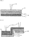
- FIGS. 1 and 2 it can be seen that in a case in which a positive electrode terminal and a negative electrode terminal are electrically connected to each other using a connecting member having a clad metal structure, processability is lowered.
- a clad metal type bus bar 100 is configured to have a structure in which an upper connecting part 102 made of aluminum is stacked on a lower connecting part 101 made of copper, and then the upper connecting part 102 and the lower connecting part 101 are rolled. Consequently, it is easy to weld a positive electrode lead 110 made of the same material as the upper connecting part 102, i.e. aluminum, to the clad metal type bus bar 100. In the same manner, it is easy to weld a negative electrode lead (not shown) made of the same material as the lower connecting part 101, i.e. copper, to the clad metal type bus bar 100.
- WO 2012/165567 A1 discloses a car battery module, wherein plate terminals protrude from the battery and a connecting part provides the connection of terminals of dissimilar metals.
- the connecting part is constituted by a basis metal and an embedded part of the dissimilar metal which is welded to the terminal of the same composition.
- JP 04 123 757 A concerning embedded plates welding technology KR 2010 0019 004 making special reference to aluminum connecting tabs as basis for dissimilar welded metals having an intermediate tab of the same material, EP 2 581 966 A1 referring to embedded materials in a recess, and EP 2 372 814 A2 disclosing embedded or buried multi-metal connecting plates used a connection element of terminals of multiple batteries, are also within the technical field of battery modules comprising battery cells, electrode terminals of which are electrically connected to each other via a connecting member.
- the present invention has been made to solve the above problems, and other technical problems that have yet to be resolved.
- a battery module comprising battery cells, electrode terminals of which are electrically connected to each other via a connecting member, wherein each of the battery cells is configured to have a structure in which an electrode assembly is mounted in a battery case made of a laminate sheet comprising a metal layer and a resin layer, and plate-shaped electrode terminals protrude from the battery case, the electrode terminals comprise a first electrode terminal and a second electrode terminal made of dissimilar metals, the connecting member comprises a main connecting part, to which the first electrode terminal is welded, the main connecting part comprising the metal of the first electrode terminal, and a buried connecting part, to which the second electrode terminal is welded, the buried connecting part comprising the metal of the second electrode terminal, wherein the main connecting part includes Cu in a case in which the first electrode terminal includes Cu, and the buried connecting part includes Al in a case in which the second electrode terminal includes Al, or wherein the main connecting part includes Al in a case in
- the battery case may be made of an aluminum laminate sheet.
- the connecting member according to the present invention is used for electrical connection between the positive electrode terminal and the negative electrode terminal, thereby improving processability.
- the connecting member includes a main connecting part, to which the first electrode terminal is welded, the main connecting part including the metal of the first electrode terminal, and a buried connecting part, to which the second electrode terminal is welded, the buried connecting part including the metal of the second electrode terminal, the buried connecting part may be buried in the main connecting part in a state in which the buried connecting part is exposed at one surface of the main connecting part.
- the first electrode terminal and the second electrode terminal may be welded respectively to the main connecting part and the buried connecting part at one surface of the main connecting part at which the buried connecting part is exposed, and the first electrode terminal and the second electrode terminal may be located on the same plane, and the connecting member may be welded to the electrode terminals in the same direction.
- the main connecting part includes Cu in a case in which the first electrode terminal includes Cu, and the buried connecting part includes Al in a case in which the second electrode terminal includes Al.
- the main connecting part includes Al in a case in which the first electrode terminal includes Al, and the buried connecting part includes Cu in a case in which the second electrode terminal includes Cu.
- the connecting member is a bus bar.
- the connecting member may be manufactured by performing shape rolling on the metal surface of the main connecting part to form a groove, treating the surface of the main connecting part using plasma, inserting the metal material of the buried connecting part into the groove formed at the main connecting part under EPC control, and rolling the main connecting part and the buried connecting part.
- the connecting member is coated with Ni.
- dissimilar metals contact each other, resistance to corrosion due to contact of the dissimilar metals may be lowered with the result that it is difficult to apply the connecting member to a device which may have a possibility of corrosion.
- the connecting member is coated with Ni as described above, a dissimilar metal compound is hardly generated during welding of the dissimilar metals, and corrosion due to contact of the dissimilar metals may be considerably reduced, which is further preferable.
- the welding between the electrode terminals and the connecting member may be any one selected from a group consisting of resistance welding, laser welding, arc welding, ultrasonic welding, E-beam welding, and hybrid welding.
- the welding may be ultrasonic welding or hybrid welding.
- the ultrasonic welding may be performed using an ultrasonic vibration of 20 KHz to 60 KHz.
- the laser welding may be performed using continuous wave (CW) laser having a laser energy density of 250 kJ/cm 2 to 1 MJ/cm 2 and an optical system at a welding speed of 50 to 200 mm/s.
- the laser welding may be performed using CW laser having a laser energy density of 300 kJ/cm 2 to 500 kJ/cm 2 and an optical system at a welding speed of 80 to 120 mm/s.
- laser oscillation may be modulated such that the laser has a predetermined frequency so as to prevent thermal damage to a welding material due to heat continuously exposed to the welding material.
- the modulation frequency may be 100 Hz to 1 kHz
- a laser oscillation rate during modulation may be 30 % to 90 % the modulation frequency. This means that, for example, in a case in which a laser oscillation rate is 50 % at 1 kHz modulation, laser output modulation is carried out at intervals of 1 ms such that laser oscillation is carried out for 500 ⁇ s, and laser oscillation is not carried out for 500 ⁇ s, which is repeated.
- a device including the battery module with the above-stated construction as a power source.
- the device may be a smart pad, a lap top computer, an electric automobile, such as an electric vehicle (EV), a hybrid electric vehicle (HEV), or a plug-in hybrid electric vehicle (PHEV), or a power storage device.
- EV electric vehicle
- HEV hybrid electric vehicle
- PHEV plug-in hybrid electric vehicle
- the present invention is not limited thereto.
- the drawings show only parts of a battery and a battery module related to welding, and other components of the battery and the battery module are omitted from the drawings.
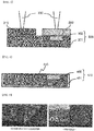
- FIG. 3 is a view typically showing a process of welding terminals to a connecting member according to the present invention.
- a connecting member 300 includes a main connecting part 301 made of a copper material and a buried connecting part 302 made of an aluminum material.
- the buried connecting part 302 is buried in the main connecting part 301 in a state in which the buried connecting part 302 is exposed at one surface of the main connecting part 301.
- a negative electrode lead 310 is made of the same material as the main connecting part 301 of the connecting member 300, i.e. copper, and a positive electrode lead 320 is made of the same material as the buried connecting part 302 of the connecting member 300, i.e. aluminum.
- a negative electrode lead 310 of one of the battery cells is located on one surface of the main connecting part 301 of the connecting member 300, and a positive electrode lead 320 of an adjacent one of the battery cells (not shown) is located on the buried connecting part 302 is exposed at one surface of the main connecting part 301 of the connecting member 300.
- laser 330 is applied to the negative electrode lead 310 and the positive electrode lead 320 to perform welding between the main connecting part 301 and the negative electrode lead 310 and welding between the buried connecting part 302 and the positive electrode lead 320.
- the negative electrode lead 310 and the positive electrode lead 320 may be connected to the connecting member 300 on the same plane without reduction of safety.
- FIG. 4 is a view showing a connecting member 400 according to the present invention which is coated with Ni.
- the connecting member 400 includes a main connecting part 401 made of a copper material and a buried connecting part 402 made of an aluminum material.
- the buried connecting part 402 is buried in the main connecting part 401 in a state in which the buried connecting part 402 is exposed at one surface of the main connecting part 401.
- the connecting member 400 is provided at the surface thereof with a coating layer 410 made of Ni. In this structure, corrosion caused by contact of dissimilar metals is considerably reduced, which is preferable.
- a negative electrode lead made of a copper material and a positive electrode lead made of an aluminum material were welded to a connecting member (comparative example) made of copper and the connecting member (example) according to the present invention shown in FIG. 3 by laser welding.
- the connecting member according to the present invention was welded
- the negative electrode lead made of the copper material was welded to the main connecting part made of the copper material
- the positive electrode lead made of the aluminum material was welded to the buried connecting part made of the aluminum material.
- Sections of the welded portions of the positive electrode leads were photographed using an electron microscope to determine whether a dissimilar metal compound had been generated. The electron microscope photographs are shown in FIG. 5 .
- a battery module uses a connecting member including a main connecting part including a metal material constituting a first electrode terminal and a buried connecting part including a metal material constituting a second electrode terminal, the buried connecting part being buried in the main connecting part in a state in which the buried connecting part is exposed at one surface of the main connecting part. Consequently, it is possible to perform welding of the electrode terminals to the connecting member without performing an additional bending process for electrical connection between the electrode terminals, particularly for series connection between the electrode terminals, unlike in the conventional art, thereby improving processability. As a result, manufacturing cost is reduced, thereby improving price competitiveness.
Landscapes
- Chemical & Material Sciences (AREA)
- Chemical Kinetics & Catalysis (AREA)
- Electrochemistry (AREA)
- General Chemical & Material Sciences (AREA)
- Inorganic Chemistry (AREA)
- Connection Of Batteries Or Terminals (AREA)
Claims (6)
- Module de batterie comprenant des éléments de batterie, dont les bornes d'électrode sont connectées électriquement entre elles par le biais d'un élément de raccordement,
chacun des éléments de batterie étant configuré pour présenter une structure dans laquelle un ensemble électrode est monté dans un boîtier de batterie composé d'une feuille stratifiée comprenant une couche métallique et une couche de résine, et des bornes d'électrode en forme de plaque faisant saillie du boîtier de batterie,
les bornes d'électrode comprenant une première borne d'électrode et une deuxième borne d'électrode, réalisées avec des métaux dissemblables,
l'élément de raccordement comprenant une partie de connexion principale, sur laquelle est soudée la première borne d'électrode, la partie de connexion principale comprenant le métal de la première borne d'électrode, et une partie de connexion enfouie, sur laquelle est soudée la deuxième borne d'électrode, la partie de connexion enfouie comprenant le métal de la deuxième borne d'électrode, la partie de connexion principale comprenant du Cu dans le cas où la première borne d'électrode comprenne du Cu, et la partie de connexion enfouie comprend de l'Al, dans le cas où la deuxième borne d'électrode comprenne de l'Al, ou la partie de connexion principale comprenant de l'Al dans le cas où la première borne d'électrode comprenne de l'Al, et, la partie de connexion enfouie comprenant du Cu, dans le cas où la deuxième borne d'électrode comprenne du Cu,
la partie de connexion enfouie étant enfouie dans la partie de connexion principale dans un état dans lequel la partie de connexion enfouie est exposée sur une surface de la partie de connexion principale, de sorte que la partie de connexion enfouie et la partie de connexion principale aient la même hauteur, de façon à former une surface lisse, et
la première borne d'électrode et la deuxième borne d'électrode sont soudées respectivement sur la partie de connexion principale et la partie de connexion enfouie sur une surface de la partie de connexion principale à laquelle la partie de connexion enfouie est exposée, et
l'élément de raccordement étant une barre omnibus, et étant revêtu de Ni. - Module de batterie selon la revendication 1, le boîtier de batterie étant réalisé avec une feuille stratifiée en aluminium.
- Module de batterie selon la revendication 1, la première borne d'électrode et la deuxième borne d'électrode étant réalisées avec des métaux dissemblables sélectionnés dans un groupe composé d'Al, de Cu, de Ni, de Fe, et d'un alliage de deux ou plusieurs de ces derniers.
- Module de batterie selon la revendication 1, la première borne d'électrode et la deuxième borne d'électrode étant situées sur le même plan, et l'élément de raccordement étant soudé sur les bornes d'électrode dans la même direction.
- Module de batterie selon la revendication 1, le soudage étant un des types sélectionnés parmi le groupe composé du soudage électrique par résistance, du soudage au laser, du soudage à l'arc, du soudage par ultrasons, du soudage par faisceau d'électrons, et d'un soudage hybride.
- Dispositif utilisant un module de batterie selon la revendication 1 en tant que source d'énergie, le dispositif étant une tablette ou un ordinateur portable, un véhicule électrique, un véhicule électrique hybride, un véhicule électrique hybride rechargeable, ou un dispositif de stockage d'énergie.
Applications Claiming Priority (2)
| Application Number | Priority Date | Filing Date | Title |
|---|---|---|---|
| KR20130079240 | 2013-07-05 | ||
| PCT/KR2014/005992 WO2015002495A1 (fr) | 2013-07-05 | 2014-07-04 | Module de batterie comprenant des éléments de connexion comprenant des métaux dissemblables |
Publications (3)
| Publication Number | Publication Date |
|---|---|
| EP2937916A1 EP2937916A1 (fr) | 2015-10-28 |
| EP2937916A4 EP2937916A4 (fr) | 2016-08-10 |
| EP2937916B1 true EP2937916B1 (fr) | 2020-05-06 |
Family
ID=52144007
Family Applications (1)
| Application Number | Title | Priority Date | Filing Date |
|---|---|---|---|
| EP14819878.1A Active EP2937916B1 (fr) | 2013-07-05 | 2014-07-04 | Module de batterie comprenant des éléments de connexion comprenant des métaux dissemblables |
Country Status (5)
| Country | Link |
|---|---|
| US (1) | US10069129B2 (fr) |
| EP (1) | EP2937916B1 (fr) |
| KR (1) | KR101629480B1 (fr) |
| CN (1) | CN105103337B (fr) |
| WO (1) | WO2015002495A1 (fr) |
Families Citing this family (9)
| Publication number | Priority date | Publication date | Assignee | Title |
|---|---|---|---|---|
| US9917291B2 (en) | 2015-05-05 | 2018-03-13 | Johnson Controls Technology Company | Welding process for a battery module |
| JP6590212B2 (ja) * | 2015-07-17 | 2019-10-16 | 株式会社オートネットワーク技術研究所 | 配線モジュール、及び蓄電モジュール |
| EP3154107B1 (fr) | 2015-10-06 | 2018-09-12 | Samsung SDI Co., Ltd. | Barre omnibus |
| JP6610269B2 (ja) * | 2016-01-08 | 2019-11-27 | 住友金属鉱山株式会社 | 異種金属の複合材からなる電解槽上導電体及びその製造方法 |
| US11130197B2 (en) | 2017-11-03 | 2021-09-28 | Greatbatch Ltd. | Laser brazed component and method therefor |
| DE102018208340B4 (de) * | 2018-05-28 | 2025-05-08 | Bayerische Motoren Werke Aktiengesellschaft | Zellkontaktieranordnung für ein Energiespeichermodul und Verfahren zum Kontaktieren von Energiespeicherzellen eines Energiespeichermoduls |
| KR102382436B1 (ko) | 2018-07-20 | 2022-04-04 | 주식회사 엘지에너지솔루션 | 파우치형 이차전지의 제조방법 |
| KR102773242B1 (ko) * | 2020-04-07 | 2025-02-27 | 주식회사 엘지에너지솔루션 | 이종금속으로 이루어진 전극 리드 및 이의 제조 방법 |
| EP4173079A1 (fr) | 2020-06-25 | 2023-05-03 | Medtronic, Inc. | Interconnexion électronique de batterie rechargeable formée |
Family Cites Families (17)
| Publication number | Priority date | Publication date | Assignee | Title |
|---|---|---|---|---|
| JPH04123757A (ja) * | 1990-09-14 | 1992-04-23 | Yuasa Corp | ニッケル電極の製造法 |
| JP5044108B2 (ja) | 2004-09-14 | 2012-10-10 | パナソニック株式会社 | 電池間接続装置 |
| KR100870461B1 (ko) | 2005-03-09 | 2008-11-25 | 주식회사 엘지화학 | 저융점 접착성 수지에 의해 안전성이 향상된 이차전지 |
| DE602007013256D1 (de) * | 2006-08-21 | 2011-04-28 | Lg Chemical Ltd | Sekundärbatterie des beuteltyps mit verbesserter sicherheit und ausgezeichneter herstellungsprozesseigenschaft |
| WO2008056908A1 (fr) * | 2006-11-06 | 2008-05-15 | Lg Chem, Ltd. | Accumulateur à sécurité améliorée par déformation de la partie de réception d'ensemble d'électrodes |
| WO2008101067A1 (fr) * | 2007-02-16 | 2008-08-21 | World Properties, Inc. | Barres bus stratifiées, et procédés de fabrication de celles-ci |
| KR20100019004A (ko) * | 2008-08-08 | 2010-02-18 | 현대자동차주식회사 | 하나의 금속으로 형성한 연결 탭을 구비하는 이차전지 |
| KR20120138790A (ko) * | 2010-03-29 | 2012-12-26 | 가부시키가이샤 고베 세이코쇼 | 버스 바 및 버스 바의 제조 방법 |
| JP5523165B2 (ja) | 2010-03-29 | 2014-06-18 | 株式会社神戸製鋼所 | バスバーの製造方法 |
| US8673479B2 (en) * | 2010-03-30 | 2014-03-18 | Samsung Sdi Co., Ltd. | Secondary battery and a secondary battery module |
| KR101217073B1 (ko) * | 2010-03-30 | 2012-12-31 | 로베르트 보쉬 게엠베하 | 이차전지 및 이차전지모듈 |
| JP5570383B2 (ja) * | 2010-10-15 | 2014-08-13 | 株式会社神戸製鋼所 | 導電性連結部材、導電性連結部材の製造方法、及び導電性連結部材が電極とされたバッテリ |
| US9350007B2 (en) | 2011-01-27 | 2016-05-24 | Neomax Materials Co., Ltd. | Connection plate for battery terminals and method for manufacturing connection plate for battery terminals |
| US9118069B2 (en) | 2011-05-10 | 2015-08-25 | GM Global Technology Operations LLC | Battery cell with integrated busbar |
| KR101915825B1 (ko) * | 2011-06-02 | 2018-11-06 | 히타치 긴조쿠 가부시키가이샤 | 전지용 부극 단자 및 전지용 부극 단자의 제조 방법 |
| CN103688391B (zh) | 2011-07-25 | 2016-03-09 | 株式会社Lg化学 | 具有改善可靠性的电池模块和采用该电池模块的电池组 |
| US20130189560A1 (en) * | 2012-01-19 | 2013-07-25 | Ford Global Technologies, Llc | Materials And Methods For Joining Battery Cell Terminals And Interconnector Busbars |
-
2014
- 2014-07-04 EP EP14819878.1A patent/EP2937916B1/fr active Active
- 2014-07-04 KR KR1020140083578A patent/KR101629480B1/ko active Active
- 2014-07-04 US US14/762,774 patent/US10069129B2/en active Active
- 2014-07-04 WO PCT/KR2014/005992 patent/WO2015002495A1/fr not_active Ceased
- 2014-07-04 CN CN201480017247.2A patent/CN105103337B/zh active Active
Non-Patent Citations (1)
| Title |
|---|
| None * |
Also Published As
| Publication number | Publication date |
|---|---|
| KR101629480B1 (ko) | 2016-06-10 |
| CN105103337B (zh) | 2019-03-05 |
| US20160141583A1 (en) | 2016-05-19 |
| WO2015002495A1 (fr) | 2015-01-08 |
| CN105103337A (zh) | 2015-11-25 |
| US10069129B2 (en) | 2018-09-04 |
| KR20150005474A (ko) | 2015-01-14 |
| EP2937916A1 (fr) | 2015-10-28 |
| EP2937916A4 (fr) | 2016-08-10 |
Similar Documents
| Publication | Publication Date | Title |
|---|---|---|
| EP2937916B1 (fr) | Module de batterie comprenant des éléments de connexion comprenant des métaux dissemblables | |
| JP4904539B2 (ja) | リード部材とその接合方法及び非水電解質蓄電デバイス | |
| TWI344234B (en) | Electrode plate for battery cell and process of preparing the same | |
| EP3020500B1 (fr) | Procédé de soudage de métaux dissemblables, barre omnibus en métaux dissemblables fabriqués à l'aide de ceux-ci, et batterie secondaire comprenant ceux-ci | |
| CN103477490B (zh) | 用活性材料以图案涂布的卷绕型电极组件及包含其的二次电池 | |
| EP1844508B1 (fr) | Accumulateur a excellente capacite d'adherence | |
| EP3258520B1 (fr) | Batterie secondaire au lithium à stabilité améliorée utilisant une languette de bimétal | |
| US20220006115A1 (en) | Battery, electric apparatus, and cell installation method | |
| CN110931695B (zh) | 电池模块、包括电池模块的电池组和包括电池组的车辆 | |
| JP2015517728A (ja) | バイメタルバスバーアセンブリ | |
| WO2008013371A1 (fr) | Ensemble électrode présentant des pattes d'électrode de même dimension dans une partie charnière de l'ensemble et cellule électrochimique contenant ledit ensemble | |
| CN108012571A (zh) | 电池模块组件的焊接过程 | |
| KR20180120027A (ko) | 이차전지용 전극리드, 이를 포함하는 파우치형 이차전지 및 배터리 모듈 | |
| KR102310033B1 (ko) | 전기차용 배터리 모듈 제조방법 및 이에 의해 제조된 전기차용 배터리 모듈 | |
| US20130122355A1 (en) | Rechargeable battery | |
| KR102751794B1 (ko) | 전극 어셈블리, 전지 셀, 전지, 전력 소비 장치, 제조 방법 및 장비 | |
| CN113924685B (zh) | 二次电池及其制造方法、电池模块以及装置 | |
| CN111799429A (zh) | 软包电池和软包电池的组装方法 | |
| JP5558878B2 (ja) | 組電池、抵抗溶接方法および組電池の製造方法 | |
| CN103000854A (zh) | 用于连接多个平行连接片的方法 | |
| EP3396737A1 (fr) | Cellule de batterie | |
| CN119864602A (zh) | 电池单元 | |
| JP5427901B2 (ja) | 電池 | |
| KR20160127559A (ko) | 전극 리드 및 이를 포함하는 고용량 전지 모듈 |
Legal Events
| Date | Code | Title | Description |
|---|---|---|---|
| PUAI | Public reference made under article 153(3) epc to a published international application that has entered the european phase |
Free format text: ORIGINAL CODE: 0009012 |
|
| 17P | Request for examination filed |
Effective date: 20150721 |
|
| AK | Designated contracting states |
Kind code of ref document: A1 Designated state(s): AL AT BE BG CH CY CZ DE DK EE ES FI FR GB GR HR HU IE IS IT LI LT LU LV MC MK MT NL NO PL PT RO RS SE SI SK SM TR |
|
| AX | Request for extension of the european patent |
Extension state: BA ME |
|
| REG | Reference to a national code |
Ref country code: DE Ref legal event code: R079 Ref document number: 602014065155 Country of ref document: DE Free format text: PREVIOUS MAIN CLASS: H01M0002260000 Ipc: H01M0002200000 |
|
| A4 | Supplementary search report drawn up and despatched |
Effective date: 20160712 |
|
| RIC1 | Information provided on ipc code assigned before grant |
Ipc: H01M 2/30 20060101ALI20160701BHEP Ipc: H01M 2/20 20060101AFI20160701BHEP Ipc: H01M 2/26 20060101ALI20160701BHEP |
|
| DAX | Request for extension of the european patent (deleted) | ||
| STAA | Information on the status of an ep patent application or granted ep patent |
Free format text: STATUS: EXAMINATION IS IN PROGRESS |
|
| 17Q | First examination report despatched |
Effective date: 20181112 |
|
| GRAP | Despatch of communication of intention to grant a patent |
Free format text: ORIGINAL CODE: EPIDOSNIGR1 |
|
| STAA | Information on the status of an ep patent application or granted ep patent |
Free format text: STATUS: GRANT OF PATENT IS INTENDED |
|
| INTG | Intention to grant announced |
Effective date: 20200128 |
|
| GRAS | Grant fee paid |
Free format text: ORIGINAL CODE: EPIDOSNIGR3 |
|
| GRAA | (expected) grant |
Free format text: ORIGINAL CODE: 0009210 |
|
| STAA | Information on the status of an ep patent application or granted ep patent |
Free format text: STATUS: THE PATENT HAS BEEN GRANTED |
|
| AK | Designated contracting states |
Kind code of ref document: B1 Designated state(s): AL AT BE BG CH CY CZ DE DK EE ES FI FR GB GR HR HU IE IS IT LI LT LU LV MC MK MT NL NO PL PT RO RS SE SI SK SM TR |
|
| REG | Reference to a national code |
Ref country code: GB Ref legal event code: FG4D |
|
| REG | Reference to a national code |
Ref country code: CH Ref legal event code: EP Ref country code: AT Ref legal event code: REF Ref document number: 1268270 Country of ref document: AT Kind code of ref document: T Effective date: 20200515 |
|
| REG | Reference to a national code |
Ref country code: DE Ref legal event code: R096 Ref document number: 602014065155 Country of ref document: DE |
|
| REG | Reference to a national code |
Ref country code: IE Ref legal event code: FG4D |
|
| REG | Reference to a national code |
Ref country code: LT Ref legal event code: MG4D |
|
| REG | Reference to a national code |
Ref country code: NL Ref legal event code: MP Effective date: 20200506 |
|
| PG25 | Lapsed in a contracting state [announced via postgrant information from national office to epo] |
Ref country code: LT Free format text: LAPSE BECAUSE OF FAILURE TO SUBMIT A TRANSLATION OF THE DESCRIPTION OR TO PAY THE FEE WITHIN THE PRESCRIBED TIME-LIMIT Effective date: 20200506 Ref country code: FI Free format text: LAPSE BECAUSE OF FAILURE TO SUBMIT A TRANSLATION OF THE DESCRIPTION OR TO PAY THE FEE WITHIN THE PRESCRIBED TIME-LIMIT Effective date: 20200506 Ref country code: NO Free format text: LAPSE BECAUSE OF FAILURE TO SUBMIT A TRANSLATION OF THE DESCRIPTION OR TO PAY THE FEE WITHIN THE PRESCRIBED TIME-LIMIT Effective date: 20200806 Ref country code: GR Free format text: LAPSE BECAUSE OF FAILURE TO SUBMIT A TRANSLATION OF THE DESCRIPTION OR TO PAY THE FEE WITHIN THE PRESCRIBED TIME-LIMIT Effective date: 20200807 Ref country code: PT Free format text: LAPSE BECAUSE OF FAILURE TO SUBMIT A TRANSLATION OF THE DESCRIPTION OR TO PAY THE FEE WITHIN THE PRESCRIBED TIME-LIMIT Effective date: 20200907 Ref country code: SE Free format text: LAPSE BECAUSE OF FAILURE TO SUBMIT A TRANSLATION OF THE DESCRIPTION OR TO PAY THE FEE WITHIN THE PRESCRIBED TIME-LIMIT Effective date: 20200506 Ref country code: IS Free format text: LAPSE BECAUSE OF FAILURE TO SUBMIT A TRANSLATION OF THE DESCRIPTION OR TO PAY THE FEE WITHIN THE PRESCRIBED TIME-LIMIT Effective date: 20200906 |
|
| REG | Reference to a national code |
Ref country code: DE Ref legal event code: R079 Ref document number: 602014065155 Country of ref document: DE Free format text: PREVIOUS MAIN CLASS: H01M0002200000 Ipc: H01M0050500000 |
|
| PG25 | Lapsed in a contracting state [announced via postgrant information from national office to epo] |
Ref country code: HR Free format text: LAPSE BECAUSE OF FAILURE TO SUBMIT A TRANSLATION OF THE DESCRIPTION OR TO PAY THE FEE WITHIN THE PRESCRIBED TIME-LIMIT Effective date: 20200506 Ref country code: BG Free format text: LAPSE BECAUSE OF FAILURE TO SUBMIT A TRANSLATION OF THE DESCRIPTION OR TO PAY THE FEE WITHIN THE PRESCRIBED TIME-LIMIT Effective date: 20200806 Ref country code: LV Free format text: LAPSE BECAUSE OF FAILURE TO SUBMIT A TRANSLATION OF THE DESCRIPTION OR TO PAY THE FEE WITHIN THE PRESCRIBED TIME-LIMIT Effective date: 20200506 Ref country code: RS Free format text: LAPSE BECAUSE OF FAILURE TO SUBMIT A TRANSLATION OF THE DESCRIPTION OR TO PAY THE FEE WITHIN THE PRESCRIBED TIME-LIMIT Effective date: 20200506 |
|
| REG | Reference to a national code |
Ref country code: AT Ref legal event code: MK05 Ref document number: 1268270 Country of ref document: AT Kind code of ref document: T Effective date: 20200506 |
|
| PG25 | Lapsed in a contracting state [announced via postgrant information from national office to epo] |
Ref country code: NL Free format text: LAPSE BECAUSE OF FAILURE TO SUBMIT A TRANSLATION OF THE DESCRIPTION OR TO PAY THE FEE WITHIN THE PRESCRIBED TIME-LIMIT Effective date: 20200506 Ref country code: AL Free format text: LAPSE BECAUSE OF FAILURE TO SUBMIT A TRANSLATION OF THE DESCRIPTION OR TO PAY THE FEE WITHIN THE PRESCRIBED TIME-LIMIT Effective date: 20200506 |
|
| PG25 | Lapsed in a contracting state [announced via postgrant information from national office to epo] |
Ref country code: IT Free format text: LAPSE BECAUSE OF FAILURE TO SUBMIT A TRANSLATION OF THE DESCRIPTION OR TO PAY THE FEE WITHIN THE PRESCRIBED TIME-LIMIT Effective date: 20200506 Ref country code: SM Free format text: LAPSE BECAUSE OF FAILURE TO SUBMIT A TRANSLATION OF THE DESCRIPTION OR TO PAY THE FEE WITHIN THE PRESCRIBED TIME-LIMIT Effective date: 20200506 Ref country code: EE Free format text: LAPSE BECAUSE OF FAILURE TO SUBMIT A TRANSLATION OF THE DESCRIPTION OR TO PAY THE FEE WITHIN THE PRESCRIBED TIME-LIMIT Effective date: 20200506 Ref country code: RO Free format text: LAPSE BECAUSE OF FAILURE TO SUBMIT A TRANSLATION OF THE DESCRIPTION OR TO PAY THE FEE WITHIN THE PRESCRIBED TIME-LIMIT Effective date: 20200506 Ref country code: CZ Free format text: LAPSE BECAUSE OF FAILURE TO SUBMIT A TRANSLATION OF THE DESCRIPTION OR TO PAY THE FEE WITHIN THE PRESCRIBED TIME-LIMIT Effective date: 20200506 Ref country code: ES Free format text: LAPSE BECAUSE OF FAILURE TO SUBMIT A TRANSLATION OF THE DESCRIPTION OR TO PAY THE FEE WITHIN THE PRESCRIBED TIME-LIMIT Effective date: 20200506 Ref country code: AT Free format text: LAPSE BECAUSE OF FAILURE TO SUBMIT A TRANSLATION OF THE DESCRIPTION OR TO PAY THE FEE WITHIN THE PRESCRIBED TIME-LIMIT Effective date: 20200506 Ref country code: DK Free format text: LAPSE BECAUSE OF FAILURE TO SUBMIT A TRANSLATION OF THE DESCRIPTION OR TO PAY THE FEE WITHIN THE PRESCRIBED TIME-LIMIT Effective date: 20200506 |
|
| REG | Reference to a national code |
Ref country code: DE Ref legal event code: R097 Ref document number: 602014065155 Country of ref document: DE |
|
| PG25 | Lapsed in a contracting state [announced via postgrant information from national office to epo] |
Ref country code: SK Free format text: LAPSE BECAUSE OF FAILURE TO SUBMIT A TRANSLATION OF THE DESCRIPTION OR TO PAY THE FEE WITHIN THE PRESCRIBED TIME-LIMIT Effective date: 20200506 Ref country code: MC Free format text: LAPSE BECAUSE OF FAILURE TO SUBMIT A TRANSLATION OF THE DESCRIPTION OR TO PAY THE FEE WITHIN THE PRESCRIBED TIME-LIMIT Effective date: 20200506 Ref country code: PL Free format text: LAPSE BECAUSE OF FAILURE TO SUBMIT A TRANSLATION OF THE DESCRIPTION OR TO PAY THE FEE WITHIN THE PRESCRIBED TIME-LIMIT Effective date: 20200506 |
|
| REG | Reference to a national code |
Ref country code: CH Ref legal event code: PL |
|
| PLBE | No opposition filed within time limit |
Free format text: ORIGINAL CODE: 0009261 |
|
| STAA | Information on the status of an ep patent application or granted ep patent |
Free format text: STATUS: NO OPPOSITION FILED WITHIN TIME LIMIT |
|
| 26N | No opposition filed |
Effective date: 20210209 |
|
| GBPC | Gb: european patent ceased through non-payment of renewal fee |
Effective date: 20200806 |
|
| REG | Reference to a national code |
Ref country code: BE Ref legal event code: MM Effective date: 20200731 |
|
| PG25 | Lapsed in a contracting state [announced via postgrant information from national office to epo] |
Ref country code: FR Free format text: LAPSE BECAUSE OF NON-PAYMENT OF DUE FEES Effective date: 20200706 Ref country code: LU Free format text: LAPSE BECAUSE OF NON-PAYMENT OF DUE FEES Effective date: 20200704 Ref country code: LI Free format text: LAPSE BECAUSE OF NON-PAYMENT OF DUE FEES Effective date: 20200731 Ref country code: CH Free format text: LAPSE BECAUSE OF NON-PAYMENT OF DUE FEES Effective date: 20200731 Ref country code: IE Free format text: LAPSE BECAUSE OF NON-PAYMENT OF DUE FEES Effective date: 20200704 |
|
| PG25 | Lapsed in a contracting state [announced via postgrant information from national office to epo] |
Ref country code: BE Free format text: LAPSE BECAUSE OF NON-PAYMENT OF DUE FEES Effective date: 20200731 Ref country code: SI Free format text: LAPSE BECAUSE OF FAILURE TO SUBMIT A TRANSLATION OF THE DESCRIPTION OR TO PAY THE FEE WITHIN THE PRESCRIBED TIME-LIMIT Effective date: 20200506 |
|
| PG25 | Lapsed in a contracting state [announced via postgrant information from national office to epo] |
Ref country code: GB Free format text: LAPSE BECAUSE OF NON-PAYMENT OF DUE FEES Effective date: 20200806 |
|
| PG25 | Lapsed in a contracting state [announced via postgrant information from national office to epo] |
Ref country code: TR Free format text: LAPSE BECAUSE OF FAILURE TO SUBMIT A TRANSLATION OF THE DESCRIPTION OR TO PAY THE FEE WITHIN THE PRESCRIBED TIME-LIMIT Effective date: 20200506 Ref country code: MT Free format text: LAPSE BECAUSE OF FAILURE TO SUBMIT A TRANSLATION OF THE DESCRIPTION OR TO PAY THE FEE WITHIN THE PRESCRIBED TIME-LIMIT Effective date: 20200506 Ref country code: CY Free format text: LAPSE BECAUSE OF FAILURE TO SUBMIT A TRANSLATION OF THE DESCRIPTION OR TO PAY THE FEE WITHIN THE PRESCRIBED TIME-LIMIT Effective date: 20200506 |
|
| PG25 | Lapsed in a contracting state [announced via postgrant information from national office to epo] |
Ref country code: MK Free format text: LAPSE BECAUSE OF FAILURE TO SUBMIT A TRANSLATION OF THE DESCRIPTION OR TO PAY THE FEE WITHIN THE PRESCRIBED TIME-LIMIT Effective date: 20200506 |
|
| REG | Reference to a national code |
Ref country code: DE Ref legal event code: R081 Ref document number: 602014065155 Country of ref document: DE Owner name: LG ENERGY SOLUTION, LTD., KR Free format text: FORMER OWNER: LG CHEM, LTD., SEOUL, KR |
|
| P01 | Opt-out of the competence of the unified patent court (upc) registered |
Effective date: 20230323 |
|
| PGFP | Annual fee paid to national office [announced via postgrant information from national office to epo] |
Ref country code: DE Payment date: 20250624 Year of fee payment: 12 |