EP2937945A2 - Connecteur de récepteur de couvercle, câble de plaque rf et connecteur d'extrémité de câble utilisé conjointement avec celui-ci - Google Patents
Connecteur de récepteur de couvercle, câble de plaque rf et connecteur d'extrémité de câble utilisé conjointement avec celui-ci Download PDFInfo
- Publication number
- EP2937945A2 EP2937945A2 EP15164396.2A EP15164396A EP2937945A2 EP 2937945 A2 EP2937945 A2 EP 2937945A2 EP 15164396 A EP15164396 A EP 15164396A EP 2937945 A2 EP2937945 A2 EP 2937945A2
- Authority
- EP
- European Patent Office
- Prior art keywords
- receptor
- cable
- cable end
- connector
- insulator
- Prior art date
- Legal status (The legal status is an assumption and is not a legal conclusion. Google has not performed a legal analysis and makes no representation as to the accuracy of the status listed.)
- Withdrawn
Links
Images


Classifications
-
- H—ELECTRICITY
- H01—ELECTRIC ELEMENTS
- H01R—ELECTRICALLY-CONDUCTIVE CONNECTIONS; STRUCTURAL ASSOCIATIONS OF A PLURALITY OF MUTUALLY-INSULATED ELECTRICAL CONNECTING ELEMENTS; COUPLING DEVICES; CURRENT COLLECTORS
- H01R13/00—Details of coupling devices of the kinds covered by groups H01R12/70 or H01R24/00 - H01R33/00
- H01R13/44—Means for preventing access to live contacts
- H01R13/447—Shutter or cover plate
-
- H—ELECTRICITY
- H01—ELECTRIC ELEMENTS
- H01R—ELECTRICALLY-CONDUCTIVE CONNECTIONS; STRUCTURAL ASSOCIATIONS OF A PLURALITY OF MUTUALLY-INSULATED ELECTRICAL CONNECTING ELEMENTS; COUPLING DEVICES; CURRENT COLLECTORS
- H01R13/00—Details of coupling devices of the kinds covered by groups H01R12/70 or H01R24/00 - H01R33/00
- H01R13/62—Means for facilitating engagement or disengagement of coupling parts or for holding them in engagement
- H01R13/627—Snap or like fastening
-
- H—ELECTRICITY
- H01—ELECTRIC ELEMENTS
- H01R—ELECTRICALLY-CONDUCTIVE CONNECTIONS; STRUCTURAL ASSOCIATIONS OF A PLURALITY OF MUTUALLY-INSULATED ELECTRICAL CONNECTING ELEMENTS; COUPLING DEVICES; CURRENT COLLECTORS
- H01R13/00—Details of coupling devices of the kinds covered by groups H01R12/70 or H01R24/00 - H01R33/00
- H01R13/648—Protective earth or shield arrangements on coupling devices, e.g. anti-static shielding
- H01R13/658—High frequency shielding arrangements, e.g. against EMI [Electro-Magnetic Interference] or EMP [Electro-Magnetic Pulse]
- H01R13/6581—Shield structure
-
- H—ELECTRICITY
- H01—ELECTRIC ELEMENTS
- H01R—ELECTRICALLY-CONDUCTIVE CONNECTIONS; STRUCTURAL ASSOCIATIONS OF A PLURALITY OF MUTUALLY-INSULATED ELECTRICAL CONNECTING ELEMENTS; COUPLING DEVICES; CURRENT COLLECTORS
- H01R13/00—Details of coupling devices of the kinds covered by groups H01R12/70 or H01R24/00 - H01R33/00
- H01R13/648—Protective earth or shield arrangements on coupling devices, e.g. anti-static shielding
- H01R13/658—High frequency shielding arrangements, e.g. against EMI [Electro-Magnetic Interference] or EMP [Electro-Magnetic Pulse]
- H01R13/6591—Specific features or arrangements of connection of shield to conductive members
- H01R13/6597—Specific features or arrangements of connection of shield to conductive members the conductive member being a contact of the connector
-
- H—ELECTRICITY
- H01—ELECTRIC ELEMENTS
- H01R—ELECTRICALLY-CONDUCTIVE CONNECTIONS; STRUCTURAL ASSOCIATIONS OF A PLURALITY OF MUTUALLY-INSULATED ELECTRICAL CONNECTING ELEMENTS; COUPLING DEVICES; CURRENT COLLECTORS
- H01R4/00—Electrically-conductive connections between two or more conductive members in direct contact, i.e. touching one another; Means for effecting or maintaining such contact; Electrically-conductive connections having two or more spaced connecting locations for conductors and using contact members penetrating insulation
- H01R4/28—Clamped connections, spring connections
-
- H—ELECTRICITY
- H01—ELECTRIC ELEMENTS
- H01R—ELECTRICALLY-CONDUCTIVE CONNECTIONS; STRUCTURAL ASSOCIATIONS OF A PLURALITY OF MUTUALLY-INSULATED ELECTRICAL CONNECTING ELEMENTS; COUPLING DEVICES; CURRENT COLLECTORS
- H01R9/00—Structural associations of a plurality of mutually-insulated electrical connecting elements, e.g. terminal strips or terminal blocks; Terminals or binding posts mounted upon a base or in a case; Bases therefor
- H01R9/03—Connectors arranged to contact a plurality of the conductors of a multiconductor cable, e.g. tapping connections
- H01R9/05—Connectors arranged to contact a plurality of the conductors of a multiconductor cable, e.g. tapping connections for coaxial cables
- H01R9/0524—Connection to outer conductor by action of a clamping member, e.g. screw fastening means
-
- H—ELECTRICITY
- H01—ELECTRIC ELEMENTS
- H01R—ELECTRICALLY-CONDUCTIVE CONNECTIONS; STRUCTURAL ASSOCIATIONS OF A PLURALITY OF MUTUALLY-INSULATED ELECTRICAL CONNECTING ELEMENTS; COUPLING DEVICES; CURRENT COLLECTORS
- H01R12/00—Structural associations of a plurality of mutually-insulated electrical connecting elements, specially adapted for printed circuits, e.g. printed circuit boards [PCB], flat or ribbon cables, or like generally planar structures, e.g. terminal strips, terminal blocks; Coupling devices specially adapted for printed circuits, flat or ribbon cables, or like generally planar structures; Terminals specially adapted for contact with, or insertion into, printed circuits, flat or ribbon cables, or like generally planar structures
- H01R12/70—Coupling devices
- H01R12/71—Coupling devices for rigid printing circuits or like structures
- H01R12/75—Coupling devices for rigid printing circuits or like structures connecting to cables except for flat or ribbon cables
Definitions
- the invention relates to a receptor connector and a RF (radio frequency) cable and a cable end connector used in conjunction therewith, more specifically to a flip-cover receptor connector, and a RF plate cable and a cable end connector used in conjunction therewith.
- RF radio frequency
- a coaxial cable is usually used for radio-frequency signal transmission of various electronic products.
- the coaxial cables may be in electrical communication with receptor connectors soldered on circuit boards of electronic products (not shown) by cable end connectors to deliver signals.
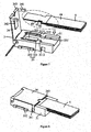
- a middle portion of a receptor connector 1 is provided with a columnar receptor central terminal 11 and a cylindrical receptor shielding terminal 13.
- the receptor shielding terminal 13 is arranged around the receptor central terminal 11.
- a bottom side of the receptor central terminal 11 is extended out of a receptor central terminal pin 12.
- a bottom side of the receptor shielding terminal 13 is extended out of a receptor shielding terminal pin 14.
- the cable end connector 2 includes a cable end central terminal 21 and a cable end shielding terminal 22, the cable end central terminal 21 being in electrical communication with a central conductor of a coaxial cable (known as core wire, not shown), the cable end shielding terminal 22 being in electrical communication with external conductors of a coaxial cable (not shown).
- the cable end connector 2 may be mated to the receptor connector 1 as shown in Figure 1 for the cable end central terminal 21 to be in electrical communication with the receptor central terminal 11, and for the cable end shielding terminal 22 to be in electrical communication with the receptor shielding terminal 13, in order for the coaxial cable to be in RF signal communication with a circuit board of an electronic product.
- main object of the invention is to provide a flip-cover receptor connector not only to fasten a RF plate cable and a cable end connector used in conjunction therewith effectively, but also to reduce a total height of the RF plate cable and the cable end connector used in conjunction therewith effectively.
- the invention serves to provide a flip-cover receptor connector used in conjunction with a RF plate cable or a cable end connector joined with a coaxial cable, including a receptor insulator, a receptor central terminal, a receptor shielding terminal and a metal cover.
- the receptor insulator is provided concavely with a placement space, the RF plate cable or the cable end connector being capable of entering the placement space.
- the receptor central terminal is provided at the receptor insulator and having a receptor central terminal contact exposed at the bottom of the placement space of the receptor insulator for receiving an electrical signal from a central conductor of the RF plate cable or the coaxial cable.
- the receptor shielding terminal is arranged at the receptor insulator, having a receptor shielding terminal contact exposed at a lateral side of the placement space of the receptor insulator for receiving an electrical signal from external conductors of the RF plate cable or the coaxial cable.
- the metal cover one end being pivoted on the receptor insulator, another end having a fastening structure, can be forced to rotate pivotally until the fastening structure thereof fastens the receptor insulator to have electrical contact with the receptor shielding terminal, forming a shielding loop providing shielding for the placement space, and preventing the RF plate cable or the cable end connector in the placement space from leaving via the placement opening longitudinally.
- a side wall of the receptor insulator constituting the placement space may be formed with a neck for the RF plate cable or the cable end connector to enter the placement space therethrough top down.
- the receptor insulator may be formed with a lateral limiting mechanism to provide limiting for the RF plate cable or the cable end connector in the placement space, in order to prevent the RF plate cable or the cable end connector from leaving the placement space via the neck laterally.
- the inner wall of the metal cover may be provided convexly with a pressing portion for pressing the RF plate cable or the cable end connector in the placement space.
- An outer wall of the metal cover has a tilt portion for lifting the metal cover.
- the present invention further provides a RF plate cable used in conjunction with the flip-cover receptor connector, having a multi-layer structure being constituted by superposing at least a plate-like central conductor, first insulators, external conductors and second insulators in sequence.
- the central conductor may be extended to a location for contact with the receptor central terminal contact and exposed.
- the first insulators may block electrical communication between the central conductor and the external conductors.
- the external conductors may be extended to a location for contact with the receptor shielding terminal contact and exposed.
- the second insulators may cover over the external conductors to provide insulation protection for the external conductors.
- the present invention further provides a cable end connector used in conjunction with the flip-cover receptor connector and joined with a coaxial cable integrally, including a cable end insulator, a cable end central terminal and a cable end shielding terminal.
- the cable end central terminal has a cable end central terminal contact and a cable end central terminal join portion, the cable end central terminal contact being exposed out of a location of the cable end insulator for contact with the receptor central terminal contact, the cable end central terminal join portion being used to join a central conductor of the coaxial cable.
- the cable end shielding terminal may clad the cable end insulator, being provided with a cable end shielding terminal contact and a plurality of cable clamps, wherein the cable end shielding terminal contact being provided at a location for contact with the receptor shielding terminal contact, while the cable clamps are used to crimp external conductors and an external insulator of the coaxial cable, respectively.
- an outer wall of the cable end shielding terminal may also have, for example, a foolproof structure formed of rabbet or hole in order for engagement with the metal cover fastened to the receptor insulator, such that whether or not the metal cover has reached engagement location is identified.
- a flip-cover receptor connector of the invention has a receptor insulator, a receptor central terminal, a receptor shielding terminal and a metal cover.
- the receptor insulator provided in the invention is formed with a placement space opening up.
- the metal cover and the receptor insulator is pivoted to be forced and rotate pivotally.
- the RF plate cable or the cable end connector may enter the placement space of the receptor insulator top down, for a receptor central terminal and a receptor shielding terminal to receive electrical signals from a central conductor and external conductors of the RF plate cable or the a coaxial cable, respectively after the metal cover fastens the receptor insulator.
- the metal cover further has a fastening structure, the fastening structure may be fastened with the receptor insulator to restrict a longitudinal movement of the RF plate cable or the cable end connector in the placement space by fastening force as it rotates pivotally toward the receptor insulator, thereby the total height is reduced after the flip-cover receptor connector of the invention is mated with the RF plate cable or the cable end connector in conjunction therewith.
- the example provides a receptor connector with a flip cover construction, fastening of a flip cover being utilized to achieve limiting movement of a RF plate cable, without a mating force provided by the receptor connector to a cable end connector joined with a coaxial cable, in order to reduce a height of a structure of the receptor connector effectively and to be applicable to modern thin technical products.
- a shape of a flip-cover receptor connector 3 is a rectangle, but various shapes, such as a circle, may be designed, without limitation to the shape shown in the figures.
- the flip-cover receptor connector 3 of the example includes a receptor insulator 31, a receptor central terminal 32, a receptor shielding terminal 33, and a metal cover 34.
- a RF plate cable 6, which is a plate-like multi-layer structure, used in conjunction with the above flip-cover receptor connector 3 is also provided.
- the RF plate cable 6 may replace a conventional coaxial cable having a multi-layer concentric ring structure.
- the multi-layer structure of the RF plate cable 6 is constituted by superposing a plate-like central conductor 61, first insulators 62, 62', external conductors 63, 63' and second insulators 64, 64'.
- the first insulators 62, 62' provide insulation protection, blocking electrical communication between the central conductor 61 and the external conductors 63, 63', respectively.
- the second insulators 64, 64' covering over the external conductors 63, 63', respectively, to provide insulation protection for the external conductors 63, 63', respectively.
- the receptor insulator 31 is provided concavely with a placement space 311, which has a placement opening 3111 opening up. As shown in Figure 7 , the RF plate cable 6 in conjunction with the flip-cover receptor connector 3 may enter the placement space 311 through the placement opening 3111 top down until abutting a bottom of the placement space 311.
- the receptor central terminal 32 is arranged at the receptor insulator 31, and has receptor central terminal contact 321 exposed at the bottom of the placement space 311 of the receptor insulator 31 for electrical contact with the central conductor 61 of the RF plate cable 6 in the placement space 311 of the receptor insulator 31, in order to receive an electrical signal from the central conductor 61 of the RF plate cable 6.
- the central conductor 61 of the RF plate cable 6 extends to a location corresponding to the receptor central terminal contact 321 and is exposed, such that electrical contact with the receptor central terminal contact 321 is available to deliver the electrical signal without a cable end connector.
- the receptor central terminal 32 also has a receptor central terminal pin 322 extending out of the receptor insulator 31 (refer to Figure 12 ), such that a circuit board is lapped to deliver the electrical signal from the central conductor 61 of the RF plate cable 6 to the circuit board.
- a cross section of the placement space 311 may be expanded from bottom to the placement opening 3111 gradually, such that a guiding plane is provided to guide the RF plate cable 6 to enter the placement space 311 step by step, in order to solve a problem that the small-sized RF plate cable 6 cannot enter the placement space 311 easily, so that time for placing the RF plate cable into the flip-cover receptor connector may be reduced effectively.
- SMT high temperature resistant plastic may be selected as a material for the receptor insulator 31, formed in an embedded injection or assemblage manner to provide locating for the receptor central terminal 32 and the receptor shielding terminal 33.
- the receptor insulator 31 also has at least one stopper 312 as a lateral limiting mechanism, the stopper 312 being extended laterally in the placement space 311 to form a neck 3112 for the RF plate cable 6 to enter the placement space 311 therethrough top down.
- the stopper 312 may provide lateral limiting for the RF plate cable 6 to prevent the RF plate cable 6 from leaving the placement space 311 via the neck 3112 laterally.
- the receptor shielding terminal 33 is arranged at the receptor insulator 31 to provide electrical shielding function.
- the receptor shielding terminal 33 has receptor shielding terminal contacts 331, 331' exposed at a lateral side and a bottom on the placement space 311 of the receptor insulator 31 for electrical contact with the external conductors 63, 63' of the RF plate cable 6, respectively, in order for electrical communication with the external conductors 63, 63' of the RF plate cable 6 to deliver the electrical signal, such as ground signal.
- the external conductors 63, 63' of the RF plate cable 6 are extend to the locations corresponding to the receptor shielding terminal contact 331, 331' and exposed, respectively, for respective electrical contact with the receptor shielding terminal contact 331, 331' and delivery of the electrical signals without the need of cable end connector.
- the receptor shielding terminal 33 further has receptor shielding terminal pins 332 extended out of the receptor insulator 31 for lapping a circuit board (not shown) to deliver the electrical signal from the external conductors 63, 63' of the RF plate cable 6 to the circuit board.
- the receptor central terminal pin 322, the receptor shielding terminal pins 332 may be selected as a SMT pin or a through hole pin to combine with the circuit board. There are two receptor shielding terminal pins 332 as shown in Figure 11 , while there is one receptor central terminal pin 322 as shown in Figure 12 , but not limited thereto. The quantities of the receptor central terminal pins 322 and the receptor shielding terminal pins 332 may be adjusted as needed.
- a metal cover 34 is pivoted with the receptor insulator 31, while another end has a fastening structure 341.
- the metal cover 34 may be forced to rotate pivotally and to be lifted upwards out of the receptor insulator 31 (also known as to rotate pivotally in a direction away from the receptor insulator 31) for the placement opening 3111 of the placement space 311 to be exposed, and for the RF plate cable to enter the placement space 311 via the placement opening 3111 top down smoothly.
- the metal cover 34 may also be forced to rotate pivotally until the fastening structure 341 thereof has fastened the receptor insulator 31 for an inner wall to provide the RF plate cable 6 with a pressing force via the placement opening 3111, in order to prevent the RF plate cable 6 from leaving the placement space 311 longitudinally via the placement opening 3111 bottom up, so that the metal cover 34 fastened with the receptor insulator 31 may prevent effectively the RF plate cable 6 from detaching the flip-cover receptor connector 3 longitudinally.
- the longitudinal limiting provided for the RF plate cable 6 by the flip-cover receptor connector 3 of the example is achieved by means of a fastening force of the metal cover 34 and the receptor insulator 31.
- a sufficient longitudinal limiting force for the RF plate cable 6 may still be provided by means of fastening of the metal cover 34 and the receptor insulator 31, such that the RF plate cable 6 will not be susceptible to an external force and detach the flip-cover receptor connector 3.
- the inner wall of the metal cover 34 is provided convexly with a pressing portion 342 for pressing the RF plate cable 6 in the placement space 311.
- the electrical contact of the receptor central terminal contact 321 and the central conductor 61 of the RF plate cable 6 is guaranteed with a pressing thrust. Even more, the electrical contact of the receptor shielding terminal contact 331' and the external conductors 63' of the RF plate cable 6 may also be guaranteed.
- the metal cover 34 may be in electrical contact with the external conductors 63 of the RF plate cable 6 as an electrical passage.
- the fastening structure 341 of the metal cover 34 may also be extended into the receptor insulator 31 for electrical contact with the receptor shielding terminal contact 331', in order to allow electrical communication for the external conductors 63, 63' of the RF plate cable 6 by means of the metal cover 34 to form a shielding loop providing shielding for the placement space 311 of the receptor insulator 31.
- an outer wall of the metal cover 34 has a tilt portion 343 for ease of forcing to exert a pivotally rotating force to the metal cover 34, such that the metal cover 34 is lifted from the receptor insulator 31 or the metal cover 34 and the receptor insulator 31 are fastened.
- a cable end connector joined with a coaxial cable is provided in the example, which may be used in conjunction with the receptor connector having a flip cover construction disclosed in the first example to reduce an entire height of a structure effectively after mating the cable end connector and the receptor connector, and is applicable to modern thin technical products.
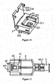
- the cable end connector 4 may include a cable end insulator 41, a cable end central terminal 42 and a cable end shielding terminal 43.
- the cable end central terminal 42 and the cable end shielding terminal 43 may be made by means of stamping with optional surface treatment to increase service life.
- a head end of the cable end shielding terminal 43 is designed as a rectangle, but not limited thereto, which may be changed to a polygon, circular arc, ellipse or irregular shape in correspondence to the flip-cover receptor connector in conjunction.
- the cable end connector 4 may enter the placement space 311 of the flip-cover receptor connector 3 top down until abutting the bottom of the placement space 311.
- the cable end central terminal is allowed for electrical contact with the receptor central terminal
- the cable end shielding terminal is allowed for electrical contact with the receptor shielding terminal for respective delivery of the electrical signal of the central conductor of the coaxial cable 5 and the external conductors.
- the cable end central terminal 42 has a cable end central terminal contact 421 and a cable end central terminal join portion 422 on head and tail ends of the cable end insulator 41, respectively.
- the cable end central terminal contact 421 is exposed at a location where the cable end insulator 41 is in contact with the receptor central terminal contact for accomplishing the electrical contact of the cable end central terminal 42 and the receptor central terminal.
- the cable end central terminal join portion 422 is used to join the central conductor 51 of the coaxial cable 5.
- the form and structure of the cable end shielding terminal 43 is designed to fit the form and structure of the cable end insulator 41, such that the cable end insulator 41 may be cladded and contained therein.
- Head end of the cable end shielding terminal 43 are provided with a cable end shielding terminal contact 431
- tail end of the cable end shielding terminal 43 are provided with a plurality of cable clamps 4311, wherein the cable end shielding terminal contact 431 is provided at a location for contact with the receptor shielding terminal contact in order for subsequent accomplishment of electrical contact between the cable end shielding terminal 43 and the receptor shielding terminal 33.
- Those cable clamps 4311 may be crimped with the external conductors 53 and an external insulator 54 of the coaxial cable 5 integrally, respectively, for the cable end shielding terminal 43 to be capable of providing functions of electrical shielding and delivering ground signal.
- An outer wall of the cable end shielding terminal 43 may also have, for example, a foolproof structure formed of rabbet or hole in order for engagement with the metal cover fastened to the receptor insulator, such that whether or not the metal cover has reached engagement location is identified.
- a raw empty hole 432 is formed on the cable end shielding terminal 43 at a location corresponding to the cable end central terminal join portion 422, and a peripheral wall of the raw empty hole 432 is extended out of a cover plate 433.
- the raw empty hole 432 can be shielded after the cover plate 433 is bent.
- a support may penetrate into the raw empty hole 432 which is not shielded by the cover plate 433 to provide support as the cable end central terminal join portion 422 joins the central conductor 51, such that the cable end central terminal join portion 422 and the central conductor 51 may be crimped integrally.
- the cover plate 433 may be bent to shield the raw empty hole 432 in order to provide shield for crimping portion of the cable end central terminal join portion 422 and the central conductor 51.
- the cable end central terminal join portion 422 may also join the central conductor 51 of the coaxial cable 5 by means of press bond, soldering or IDC(insulation displacement connection) etc., not limited to crimping disclosed in the example.
- a hollow frame design is used for the cable end insulator 41, at which tail end a through-hole 411 for containing the cable end central terminal join portion 422 is formed in a middle portion. Further, A trench 413 is formed on a side wall 412 on which the cable end insulator 41 and the through-hole 411 are adjacent for the central conductor 51 of the coaxial cable 5 to pass and enter the through-hole 411 and join with the cable end central terminal join portion 422.
- the outer wall of the side wall 412 may also be provided for a front end of an internal insulation layer 52 of the coaxial cable 5 to abut in favor of subsequent join operation of the central conductor 51 and the cable end central terminal join portion 422, and maintaining suspension of the central conductor 51 in the trench 413, while the central conductor 51 and the cable end shielding terminal 43 are separated to prevent electrical signal transmission of the central conductor 51 from influence due to interference.
- a pair of wing panels are extended on both sides of a tail portion of the cable end shielding terminal 43.
- the pair of wing panels may be bent inward relatively to cover the through-hole 411, and provide shield for the join portion of the cable end central terminal join portion 422 and the central conductor 51 to reduce the extent of external influence for signal delivery of central conductor 51.
- the invention provides a flip-cover receptor connector and a RF plate cable used in conjunction therewith and a cable end connector joined with a coaxial cable.
- the flip-cover receptor connector of the invention has a receptor insulator, a receptor central terminal, a receptor shielding terminal and a metal cover.
- the receptor insulator has a placement space for accommodating the RF plate cable or the cable end connector.
- One end of a metal cover and the receptor insulator is pivoted to be forced and rotate pivotally. As the metal cover rotates pivotally in a direction away from the receptor insulator, a placement space of the receptor insulator is exposed, so that the RF plate cable or the cable end connector may be placed.
- a receptor central terminal is used to receive electrical signal from the RF plate cable or the central conductor of the coaxial cable.
- a receptor shielding terminal is used to receive electrical signal from the RF plate cable or the external conductors of the coaxial cable.
- Another end of the metal cover has a fastening structure.
- the fastening structure of the metal cover may be fastened with the receptor insulator.
- longitudinal movement of the RF plate cable or the cable end connector in the placement space is restricted.
- a sufficient restriction force may be provided for longitudinal movement of the RF plate cable or the cable end connector by fastening the metal cover and the receptor insulator even though height of the flip-cover receptor connector is very small, such that it does not tend to leave the placement space of the receptor insulator due to external force impact.
- the structure height after combining the flip-cover receptor connector and the RF plate cable or the cable end connector in conjunction therewith according to the invention may be reduced effectively to be applicable to modern or future thin technical products.
Landscapes
- Coupling Device And Connection With Printed Circuit (AREA)
- Insulated Conductors (AREA)
- Details Of Connecting Devices For Male And Female Coupling (AREA)
- Connector Housings Or Holding Contact Members (AREA)
Applications Claiming Priority (1)
| Application Number | Priority Date | Filing Date | Title |
|---|---|---|---|
| CN201410164751.7A CN105098456B (zh) | 2014-04-23 | 2014-04-23 | 掀盖式板端连接器及与其搭配使用的rf平板式线缆与线端连接器 |
Publications (2)
| Publication Number | Publication Date |
|---|---|
| EP2937945A2 true EP2937945A2 (fr) | 2015-10-28 |
| EP2937945A3 EP2937945A3 (fr) | 2016-03-16 |
Family
ID=52997321
Family Applications (1)
| Application Number | Title | Priority Date | Filing Date |
|---|---|---|---|
| EP15164396.2A Withdrawn EP2937945A3 (fr) | 2014-04-23 | 2015-04-21 | Connecteur de récepteur de couvercle, câble de plaque rf et connecteur d'extrémité de câble utilisé conjointement avec celui-ci |
Country Status (5)
| Country | Link |
|---|---|
| US (1) | US9318835B2 (fr) |
| EP (1) | EP2937945A3 (fr) |
| JP (1) | JP6362172B2 (fr) |
| CN (1) | CN105098456B (fr) |
| TW (1) | TWI599120B (fr) |
Families Citing this family (7)
| Publication number | Priority date | Publication date | Assignee | Title |
|---|---|---|---|---|
| JP2019030356A (ja) * | 2017-08-04 | 2019-02-28 | オリンパス株式会社 | 内視鏡用コネクタユニットおよび内視鏡システム |
| CN109411967B (zh) * | 2017-08-17 | 2025-02-18 | 春源科技(深圳)有限公司 | 高频rf连接构件及其高频rf跳线与板端连接器 |
| CN110768037B (zh) * | 2018-07-27 | 2025-05-20 | 春源科技(深圳)有限公司 | 超高频极细同轴rf连接器总成 |
| JP7143207B2 (ja) * | 2018-12-21 | 2022-09-28 | ヒロセ電機株式会社 | 対の圧着片を有するハウジングを備えた同軸ケーブルコネクタ |
| CN116325370A (zh) * | 2020-10-13 | 2023-06-23 | 申泰公司 | 用于高速数据传输的具有环形连接器的竖直插入互连系统 |
| CN115986501A (zh) | 2022-12-13 | 2023-04-18 | 东莞立讯技术有限公司 | 线缆连接器以及电连接器 |
| TWI867395B (zh) | 2022-12-13 | 2024-12-21 | 大陸商東莞立訊技術有限公司 | 連接器模組及其組裝方法 |
Family Cites Families (17)
| Publication number | Priority date | Publication date | Assignee | Title |
|---|---|---|---|---|
| US5482477A (en) * | 1994-06-28 | 1996-01-09 | The Whitaker Corporation | Micro-miniature coaxial connector with positive locking member |
| JP4152019B2 (ja) * | 1998-09-30 | 2008-09-17 | 日本圧着端子製造株式会社 | 多極同軸コネクタ |
| JP2002324633A (ja) * | 2001-04-27 | 2002-11-08 | Mitsubishi Cable Ind Ltd | 同軸ケーブル用コネクタ |
| DE60310002T2 (de) * | 2002-09-28 | 2007-04-26 | Tyco Electronics Amp Gmbh | Geschirmte Steckeranordnung für die Datenübertragung |
| JP2004247086A (ja) * | 2003-02-12 | 2004-09-02 | Sumitomo Wiring Syst Ltd | 垂直嵌合型コネクタ |
| JP4889243B2 (ja) * | 2005-06-09 | 2012-03-07 | モレックス インコーポレイテド | コネクタ装置 |
| JP2007286553A (ja) * | 2006-04-20 | 2007-11-01 | Mitsumi Electric Co Ltd | 電気光変換モジュール |
| JP4157572B2 (ja) * | 2006-06-06 | 2008-10-01 | ヒロセ電機株式会社 | 光電気複合型コネクタ |
| JP4097681B1 (ja) * | 2007-02-01 | 2008-06-11 | 日本航空電子工業株式会社 | コネクタ |
| JP4633102B2 (ja) * | 2007-10-26 | 2011-02-16 | モレックス インコーポレイテド | カード用コネクタ |
| JP2009199809A (ja) * | 2008-02-20 | 2009-09-03 | Mitsumi Electric Co Ltd | コネクタ、光伝送モジュールおよび光−電気伝送モジュール |
| US7892028B2 (en) * | 2009-01-20 | 2011-02-22 | Hon Hai Precision Ind. Co., Ltd. | Cable connector assembly |
| CN202503145U (zh) * | 2012-03-08 | 2012-10-24 | 东莞市泰康电子科技有限公司 | Rf同轴电缆连接器组件 |
| CN102842838B (zh) * | 2012-08-01 | 2015-01-07 | 番禺得意精密电子工业有限公司 | 线缆连接器的制造方法及其线缆连接器 |
| JP6278586B2 (ja) * | 2012-09-10 | 2018-02-14 | 日本航空電子工業株式会社 | 同軸コネクタ |
| CN203056204U (zh) * | 2013-01-18 | 2013-07-10 | 昆山科信成电子有限公司 | 具有线芯限位机构的rf同轴连接器 |
| CN203871545U (zh) * | 2014-04-23 | 2014-10-08 | 春源科技(深圳)有限公司 | 掀盖式板端连接器及与其搭配使用的rf平板式线缆与线端连接器 |
-
2014
- 2014-04-23 CN CN201410164751.7A patent/CN105098456B/zh not_active Expired - Fee Related
-
2015
- 2015-04-20 US US14/691,282 patent/US9318835B2/en active Active
- 2015-04-21 TW TW104112776A patent/TWI599120B/zh active
- 2015-04-21 EP EP15164396.2A patent/EP2937945A3/fr not_active Withdrawn
- 2015-04-22 JP JP2015087646A patent/JP6362172B2/ja not_active Expired - Fee Related
Non-Patent Citations (1)
| Title |
|---|
| None |
Also Published As
| Publication number | Publication date |
|---|---|
| EP2937945A3 (fr) | 2016-03-16 |
| US9318835B2 (en) | 2016-04-19 |
| CN105098456B (zh) | 2017-11-07 |
| TWI599120B (zh) | 2017-09-11 |
| JP6362172B2 (ja) | 2018-07-25 |
| TW201541747A (zh) | 2015-11-01 |
| CN105098456A (zh) | 2015-11-25 |
| US20150325941A1 (en) | 2015-11-12 |
| JP2015211037A (ja) | 2015-11-24 |
Similar Documents
| Publication | Publication Date | Title |
|---|---|---|
| US9318835B2 (en) | Flip-cover receptor connector, and RF plate cable and cable end connector used in conjunction therewith | |
| US10581205B2 (en) | High-frequency ultra-fine coaxial RF connection member as well as high-frequency ultra-fine coaxial RF jumper and receptor connector thereof | |
| US8011954B2 (en) | Shielded connector | |
| US20180151967A1 (en) | Board to Board Connector Assembly | |
| EP2429039B1 (fr) | Connecteur électrique et son procédé de fabrication | |
| US9059521B2 (en) | Coaxial cable connector assembly and a receptor connector | |
| US8777637B2 (en) | Connector for connecting a coaxial cable and a circuit board and related transmission interface as well as assembly method therewith | |
| CN106935995A (zh) | 板对板连接器总成 | |
| US20130225004A1 (en) | Electrical connector assembly and printed circuit board configured to electrically couple to a communication cable | |
| EP3751671A1 (fr) | Connecteur mâle de câble coaxial pour transmettre des signaux de super haute fréquence | |
| US6575762B2 (en) | Connection of coaxial cable to a circuit board | |
| EP3751672A1 (fr) | Connecteur de câble coaxial compact pour transmettre des signaux de super haute fréquence | |
| US11005202B2 (en) | Connector | |
| US20150382454A1 (en) | Spilled adhesive guide structure of flexible circuit board | |
| US11978984B2 (en) | Signal cable connection device having a folded wire | |
| CN207459353U (zh) | 高频rf连接构件及其高频rf跳线与板端连接器 | |
| KR101212716B1 (ko) | 동축 커넥터 | |
| US9793623B2 (en) | Coaxial cable connector assembly and a receptor connector | |
| US20110287642A1 (en) | Cable connector assembly employing separate inter connecting conductors and method for assembling the same | |
| JP6986596B2 (ja) | 超高周波信号伝送用小型コネクタ | |
| CN220710773U (zh) | 电连接器 | |
| TWI496369B (zh) | 同軸線纜連接器總成及板端連接器 | |
| US20150263410A1 (en) | Antenna assembly with multiple component and assembly method of the same | |
| KR101528316B1 (ko) | 실장 강도가 향상된 리셉터클 커넥터 | |
| JP2023067978A (ja) | 電気コネクタ及び電気コネクタ対 |
Legal Events
| Date | Code | Title | Description |
|---|---|---|---|
| PUAI | Public reference made under article 153(3) epc to a published international application that has entered the european phase |
Free format text: ORIGINAL CODE: 0009012 |
|
| AK | Designated contracting states |
Kind code of ref document: A2 Designated state(s): AL AT BE BG CH CY CZ DE DK EE ES FI FR GB GR HR HU IE IS IT LI LT LU LV MC MK MT NL NO PL PT RO RS SE SI SK SM TR |
|
| AX | Request for extension of the european patent |
Extension state: BA ME |
|
| PUAL | Search report despatched |
Free format text: ORIGINAL CODE: 0009013 |
|
| AK | Designated contracting states |
Kind code of ref document: A3 Designated state(s): AL AT BE BG CH CY CZ DE DK EE ES FI FR GB GR HR HU IE IS IT LI LT LU LV MC MK MT NL NO PL PT RO RS SE SI SK SM TR |
|
| AX | Request for extension of the european patent |
Extension state: BA ME |
|
| RIC1 | Information provided on ipc code assigned before grant |
Ipc: H01R 9/05 20060101ALI20160211BHEP Ipc: H01R 13/6581 20110101ALI20160211BHEP Ipc: H01R 13/447 20060101AFI20160211BHEP Ipc: H01R 12/75 20110101ALN20160211BHEP Ipc: H01R 13/6597 20110101ALI20160211BHEP |
|
| STAA | Information on the status of an ep patent application or granted ep patent |
Free format text: STATUS: THE APPLICATION IS DEEMED TO BE WITHDRAWN |
|
| 18D | Application deemed to be withdrawn |
Effective date: 20160917 |