EP2937972A1 - Système de transmission d'énergie sans fil - Google Patents
Système de transmission d'énergie sans fil Download PDFInfo
- Publication number
- EP2937972A1 EP2937972A1 EP13873708.5A EP13873708A EP2937972A1 EP 2937972 A1 EP2937972 A1 EP 2937972A1 EP 13873708 A EP13873708 A EP 13873708A EP 2937972 A1 EP2937972 A1 EP 2937972A1
- Authority
- EP
- European Patent Office
- Prior art keywords
- electrode
- power transmission
- disposed
- electrodes
- coupler
- Prior art date
- Legal status (The legal status is an assumption and is not a legal conclusion. Google has not performed a legal analysis and makes no representation as to the accuracy of the status listed.)
- Granted
Links
Images













Classifications
-
- H—ELECTRICITY
- H02—GENERATION; CONVERSION OR DISTRIBUTION OF ELECTRIC POWER
- H02J—ELECTRIC POWER NETWORKS; CIRCUIT ARRANGEMENTS OR SYSTEMS FOR SUPPLYING OR DISTRIBUTING ELECTRIC POWER; SYSTEMS FOR STORING ELECTRIC ENERGY
- H02J50/00—Circuit arrangements or systems for wireless supply or distribution of electric power
- H02J50/10—Circuit arrangements or systems for wireless supply or distribution of electric power using inductive coupling
- H02J50/12—Circuit arrangements or systems for wireless supply or distribution of electric power using inductive coupling of the resonant type
-
- H—ELECTRICITY
- H02—GENERATION; CONVERSION OR DISTRIBUTION OF ELECTRIC POWER
- H02J—ELECTRIC POWER NETWORKS; CIRCUIT ARRANGEMENTS OR SYSTEMS FOR SUPPLYING OR DISTRIBUTING ELECTRIC POWER; SYSTEMS FOR STORING ELECTRIC ENERGY
- H02J50/00—Circuit arrangements or systems for wireless supply or distribution of electric power
- H02J50/05—Circuit arrangements or systems for wireless supply or distribution of electric power using capacitive coupling
Definitions
- the present invention relates to a wireless power transmission system.
- Patent Document 1 discloses a wireless power transmission device which performs transmission of power between two non-contact electric circuits by using electromagnetic induction.
- Patent Document 1 Japanese Patent Application Laid-open No. H8-340285
- the present invention is characterized by a wireless power transmission system transmitting alternating-current power from a power transmission device to a power reception device, wherein the power transmission device has: a first and a second electrode which are disposed across a predetermined distance, in which a total width including the predetermined distance is ⁇ /2 ⁇ or less as a near field, the first and the second electrode each having a rotationally symmetrical shape with respect to a common center axis; a first and a second connection line electrically connecting the first and the second electrode and two output terminals of an alternating-current power generating unit, respectively; and a first inductor residing between the first and the second electrode and at least one of the two output terminals of the alternating current power generating unit, and the power reception device has: a third and a fourth electrode which are disposed across a predetermined distance, in which a total width including the predetermined distance is ⁇ /2 ⁇ or less as a near field, the third and the fourth electrode each having a rotationally symmetric
- the first electrode has a platy polygonal or circular shape
- the second electrode has a platy polygonal or circular annular shape disposed to surround the first electrode and is disposed on a same plane to have a center axis corresponding to that of the first electrode
- the third electrode has a platy polygonal or circular shape
- the fourth electrode has a platy polygonal or circular annular shape disposed to surround the third electrode and is disposed on a same plane to have a center axis corresponding to that of the third electrode
- the first and the second electrode and the third and the fourth electrode are disposed to oppose each other across a distance of ⁇ /2 ⁇ or less as a near field.
- one aspect of the present invention is characterized in that at least one of the first to the fourth electrode has a cutout in a radial direction.
- a cutout for attaching an electrode can be provided without leading to deterioration in characteristics.
- one aspect of the present invention is characterized in that at least one of the first electrode and the third electrode has an annular shape.
- a through hole for attaching an electrode can be provided without leading to deterioration in characteristics.
- one aspect of the present invention is characterized in that at least one of the first to the fourth electrode has a three-dimensional structure extending in an axial direction.
- a member having a three-dimensional shape can be used as an electrode.
- first and the second electrode have a polygonal or circular cylindrical shape and the third and the fourth electrode have a polygonal or circular cylindrical shape disposed to surround the first and the second electrode, respectively, and are disposed to have a center axis corresponding to that of the first and the second electrode, and the first and the third electrode and the second and the fourth electrode are disposed to oppose each other across a distance of ⁇ /2 ⁇ or less as a near field.
- Fig. 1 illustrates a detailed structural example of a power transmission coupler constituting a wireless power transmission system utilizing series resonance.
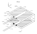
- a power transmission coupler 110 is formed by disposing electrodes 111, 112 constituted of a conductive member having a rectangular shape on a front surface 118A of a circuit board 118 constituted of an insulating member (dielectric substrate) having a rectangular plate shape.
- electrodes and so on are not disposed on a rear surface 118B of the circuit board 118.
- the electrodes 111, 112 are formed of a conductive thin film of copper or the like.
- the electrodes 111, 112 are disposed in parallel at positions separated by a predetermined distance d1. Further, a width D of the electrodes 111, 112 including the distance d1 is set to be narrower than a near field denoted by ⁇ /2 ⁇ where ⁇ is a wavelength of electric fields emitted from these electrodes.
- connection lines 115, 116 are disposed to avoid areas of the electrodes 111, 112 and an area sandwiched between them, and are also disposed to extend in a direction to depart from these areas (leftward and downward direction in Fig. 1 ). More particularly, they are disposed to avoid respective rectangular areas of the electrodes 111, 112 and the area sandwiched between these two electrodes 111, 112, and also disposed to extend in the direction to depart from these areas.
- connection lines 115, 116 are, for example, constituted of a coaxial cable or a balanced cable. Note that other ends of the connection lines 115, 116 are connected respectively to output terminals of a not-illustrated alternating-current power generating unit. By connecting the alternating-current power generating unit to the power transmission coupler 110 by the connection lines 115, 116, a power transmission device is constituted.
- the power transmission coupler 110 constitutes a series resonance circuit with capacitance C of a capacitor formed by disposing the electrodes 111, 112 across the predetermined distance d1 and inductance L of the inductors 113, 114, and thus has a peculiar resonance frequency f c due to them.
- a power reception coupler 120 has the same structure as the power transmission coupler 110, and is formed by disposing electrodes 121, 122 constituted of a conductive member having a rectangular shape and inductors 123, 124 on a front surface 128A of a circuit board 128, and connecting connection lines 125, 126 to other ends of the inductors 123, 124.
- a resonance frequency f c of a series resonance circuit due to capacitance C of a capacitor formed by the electrodes 121, 122 and inductance L of the inductors 123, 124 is set to be substantially the same as that of the power transmission coupler 110.
- the connection lines 125, 126 are, for example, constituted of a coaxial cable or a balanced cable.
- a not-illustrated load is connected to other ends of the connection lines 125, 126 of the power reception coupler 120.
- Fig. 2 is a view illustrating a state that the power transmission coupler 110 and the power reception coupler 120 are disposed to oppose each other. As illustrated in this view, the power transmission coupler 110 and the power reception coupler 120 are disposed so that the circuit boards 118, 128 are in parallel across a distance d2 and the front surfaces 118A, 128A of the circuit boards 118, 128 oppose each other.
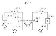
- Fig. 3 is a diagram illustrating an equivalent circuit of the wireless power transmission system 1 illustrated in Fig. 2 .
- an alternating-current power generating unit 211 generates and outputs alternating-current power with a frequency corresponding to the resonance frequency.
- a power supply unit load 212 exhibits a value equal to characteristic impedances of the connection lines 115, 116 and the connection lines 125, 126, and has a value of Z0.
- An inductor 213 corresponds to the inductors 113, 114 and has an element value of L1.
- a resistor 214 exhibits resistance which accompanies a transmission side circuit, mainly the inductor, and has an element value of R1.
- a capacitor 215 is a capacitor of an element value C1 occurring between the electrodes 111, 112.
- a capacitor 221 is a capacitor of an element value C2 occurring between the electrodes 121, 122.
- An inductor 222 corresponds to the inductors 123, 124 and has an element value of L2.
- a resistor 223 exhibits resistance which accompanies a reception side circuit, mainly the inductor, and has an element value of R2.
- a load 224 is supplied with power outputted from the alternating-current power generating unit 211 and transmitted via the power transmission coupler and the power reception coupler.
- a capacitor 241 denotes a capacitor occurring between the electrodes 111, 112 and the electrodes 121, 122 and has an element value of Cm1.
- the load 224 is, for example, constituted of a rectifying device, a secondary battery, and so on. Of course, it may be constituted of other elements.
- 2 ) from the power transmission coupler 110 to the power reception coupler 120 and reflection loss ⁇ 11 (
- 2 ), in the case where the power transmission coupler 110 and the power reception coupler 120 of the wireless power transmission system illustrated in Fig. 2 are disposed to oppose each other across a distance of 20 cm (the case where d2 20 cm).
- the horizontal axis denotes frequency (MHz) of transmitted alternating-current power
- the vertical axis denotes transmission efficiency.
- the inductors 113, 114, 123, 124 are each wound 13 times and has an inductance value of 2.8 ⁇ H, sizes (D and L) of the circuit boards 118, 128 are 250 x 250 mm, and the gap d1 between the electrodes 111, 112 and the electrodes 121, 122 is 34.4 mm.
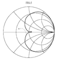
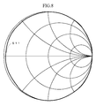
- Fig. 5 illustrates a smith chart of impedance S11 of the power transmission coupler 110 of the wireless power transmission system utilizing series resonance illustrated in Fig. 2 .
- a port impedance of the measuring apparatus is set to a value equal to a characteristic impedance Z0 (real value) of a connection line.
- Z0 real value
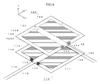
- Fig. 6 is a view illustrating a state that the power reception coupler 120 of the wireless power transmission system illustrated in Fig. 2 is disposed by rotating 90 degrees counterclockwise.
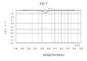
- Fig. 7 is a diagram illustrating frequency characteristics of transmission efficiency ⁇ 21 from the power transmission coupler 110 to the power reception coupler 120 and reflection loss ⁇ 11 in the disposition state of Fig. 6 . As illustrated in Fig. 7 , the transmission efficiency ⁇ 21 becomes 0 and the reflection loss ⁇ 11 becomes a value close to 1, and thus most of the power inputted to the power transmission coupler 110 is reflected and not transmitted to the power reception coupler 120. Further, as illustrated in Fig.
- Fig. 9 is a perspective view of the embodiment
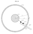
- Fig. 10 is a plan view seeing the embodiment illustrated in Fig. 9 from a Z direction.
- a power transmission coupler 310 is constituted of a circular center electrode 311, a ring-shaped annular electrode 312, inductors 313, 314, and connection lines 315, 316
- a power reception coupler 320 is constituted of a circular center electrode 321, a ring-shaped annular electrode 322, inductors 323, 324, and connection lines 325, 326.
- Fig. 9 and Fig. 10 sizes of the respective elements constituting the power transmission coupler 310 and the power reception coupler 320 are the same. Of course, even when the sizes of the respective elements are different, power can be transmitted by adjusting the sizes so that the resonance frequency is the same. Note that although only the electrodes are illustrated in the examples of Fig. 9 and Fig. 10 , the electrodes can be formed on a substrate or base material formed of a glass epoxy substrate, a glass composite substrate, or the like, similarly to Fig. 1 and Fig. 2 .
- the center electrode 311 is constituted of a platy conductive member (for example, a member of copper, aluminum, or the like) having a circular shape with a radius r1.
- the annular electrode 312 is constituted of a platy conductive member having an annular shape with an outer radius r2 and a width w. Note that the center electrode 311 and the annular electrode 312 are disposed on a same plane, and the distance between an outer periphery of the center electrode 311 and an inner periphery of the annular electrode 312 is d1.
- One end of the inductor 313 is connected to the center electrode 311, and the other end is connected to one end of the connection line 315.
- connection lines 315, 316 are, for example, constituted of a coaxial cable or a balanced cable. Other ends of the connection lines 315, 316 are connected respectively to output terminals of a not-illustrated alternating-current power generating unit.
- a power transmission device is constituted. Note that a resonance frequency of a series resonance circuit due to capacitance C of a capacitor formed by the center electrode 311 and the annular electrode 312 and inductance L of the inductors 313, 314 is f c .
- the center electrode 321 is constituted of a platy conductive member having a circular shape with a radius r1.
- the annular electrode 322 is constituted of a platy conductive member having an annular shape with an outer radius r2 and a width w.
- the center electrode 321 and the annular electrode 322 are disposed on a same plane, and the distance between an outer periphery of the circular center electrode 321 and an inner periphery of the annular electrode 322 is d1. Further, the plane on which the center electrode 311 and the annular electrode 312 are disposed and the plane on which the center electrode 321 and the annular electrode 322 are disposed are kept substantially in parallel.
- connection lines 325, 326 are, for example, constituted of a coaxial cable or a balanced cable. Other ends of the connection lines 325, 326 are connected respectively to input terminals of a not-illustrated load.
- a resonance frequency f c of a series resonance circuit due to capacitance C of a capacitor formed by the center electrode 321 and the annular electrode 322 and inductance L of the inductors 323, 324 is set to be the same as that of the power transmission coupler 310.
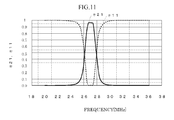
- 2 ) from the power transmission coupler 310 to the power reception coupler 320 and reflection loss ⁇ 11 ( S 11
- 2 ), in the case where the power transmission coupler 310 and the power reception coupler 320 of the wireless power transmission system illustrated in Fig. 9 and Fig. 10 are disposed to oppose each other across a distance of 20 cm (the case where d2 20 cm).
- the radius r1 of the center electrodes 311, 321 is 7 cm
- the diameter r2 of outer peripheries of the annular electrodes 312, 322 is 24 cm
- the width w of the annular electrodes 312, 322 is 1.5 cm
- d1 is set to 15.5 cm.
- the inductors 313, 314, 323, 324 are each wound 13 times and set to have an inductance value of 2.8 ⁇ H.
- the horizontal axis denotes frequency (MHz) of transmitted alternating-current power
- the vertical axis denotes transmission efficiency.
- a transmission efficiency of about 96% is achieved around 27 MHz.
- Fig. 12 illustrates a smith chart of impedance S11 of the power transmission coupler 310 of the wireless power transmission system illustrated in Fig. 9 and Fig. 10 .
- a port impedance of the measuring apparatus is set to a value equal to a characteristic impedance Z0 (real value) of a connection line.
- Z0 real value
- the center electrode 311 and the annular electrode 312 are coupled by electric field resonance to the center electrode 321 and the annular electrode 322, and alternating-current power is transmitted by an electric field from the center electrode 311 and the annular electrode 312 to the center electrode 321 and the annular electrode 322. That is, in the embodiment illustrated in Fig. 9 , since the center electrode 311 and the annular electrode 312 and the center electrode 321 and the annular electrode 322 are disposed across the distance d2 shorter than ⁇ /2 ⁇ as a near field, the center electrode 321 and the annular electrode 322 are disposed in an area where electric field components emitted from the center electrode 311 and the annular electrode 312 are dominant.
- a resonance frequency due to the capacitor formed between the center electrode 311 and the annular electrode 312 and the inductors 313, 314 and a resonance frequency due to the capacitor formed between the center electrode 321 and the annular electrode 322 and the inductors 323, 324 are set to be substantially equal.
- Fig. 13 is a diagram illustrating an electric field distribution of the embodiment illustrated in Fig. 9
- Fig. 14 illustrates the electric field distribution of Fig. 10
- the direction of an arrow indicates the direction of an electric field
- the size of an arrow indicates the intensity of an electric field.
- electric fields in the vicinities of the power transmission coupler 310 and the power reception coupler 320 are formed axially symmetrically with respect to the center axis of these couplers. Accordingly, when the power transmission coupler 310 and the power reception coupler 320 are rotated in either direction about the axis, deterioration in characteristics is small.
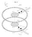
- Fig. 15 is a view illustrating a state that the power reception coupler 320 is rotated 90 degrees counterclockwise in the embodiment illustrated in Fig. 9 .
- Fig. 16 is a diagram illustrating frequency characteristics of transmission efficiency ⁇ 21 from the power transmission coupler 310 to the power reception coupler 320 and reflection loss ⁇ 11 in the state illustrated in Fig. 15
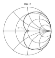
- Fig. 17 is a smith chart of impedance S11 of the power transmission coupler 310 in the same state.
- a transmission efficiency at 27 MHz is about 96%, and there is no deterioration in characteristics from the state illustrated in Fig. 9 .
- Fig. 17 also regarding the input impedance, there is no change from the state illustrated in Fig. 9 .
- the embodiment of the present invention it is possible to wirelessly transmit power from the power transmission coupler 310 to the power reception coupler 320 with high efficiency of 90 percent or more. Further, according to the embodiment of the present invention, even when the electrodes are rotated about the axis, changes in characteristics can be made quite small.
- the above embodiment is an example, and it is needless to mention that the present invention is not limited to the cases as described above.
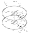
- the completely round center electrodes 311, 321 and the completely round annular electrodes 312, 322 are used, but for example, as illustrated in Fig. 18 , the center electrodes 311, 321 may have cutouts 311 a, 321 a extending from the outer periphery to the center, and the annular electrodes 312, 322 may have cutouts 312a, 322a in a part.
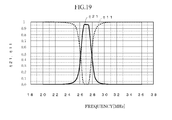
- Fig. 19 illustrates frequency characteristics of transmission efficiency ⁇ 21 and reflection loss ⁇ 11 of the embodiment illustrated in Fig. 18
- Fig. 20 is a smith chart of input impedance S 11. From comparison of these diagrams with Fig. 11 and Fig. 12 , changes in characteristics hardly occur even when the cutouts are provided. Thus, when such cutouts are provided, the transmission efficiency hardly deteriorates.
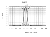
- Fig. 21 is a view illustrating a state that the power reception coupler 320 of Fig. 18 is rotated 90 degrees counterclockwise. In such a state, the positions of the cutouts 311a, 321a and the cutouts 312a, 322a do not correspond. However, changes in characteristics hardly occur even in such a state. More particularly, Fig. 22 illustrates frequency characteristics of transmission efficiency ⁇ 21 and reflection loss ⁇ 11 of the embodiment illustrated in Fig. 21 , and Fig. 23 is a smith chart of input impedance S11. From comparison of these diagrams with Fig. 19 and Fig. 20 , changes in characteristics hardly occur when the power reception coupler 320 is rotated.
- the same is true in the case where the power transmission coupler 310 is rotated.
- the cutouts are provided in all of the center electrodes 311, 321 and the annular electrodes 312, 322, but the cutouts may be provided in at least one of them.
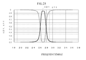
- Fig. 24 illustrates another variant embodiment. Specifically, Fig. 24 illustrates an embodiment in which the center electrodes 311, 321 are made annular by providing through holes 311b, 321b in the center electrodes 311, 321, respectively. In this example, the through holes 311b, 321b with a radius r3 are formed in the centers of the center electrodes 311, 321, respectively. Note that the other structure is the same as in Fig. 9 .
- Fig. 25 illustrates frequency characteristics of transmission efficiency ⁇ 21 and reflection loss ⁇ 11 of the embodiment illustrated in Fig. 24
- Fig. 26 is a smith chart of input impedance S11. From comparison of these diagrams with Fig. 11 and Fig. 12 , changes in characteristics hardly occur even when the through holes 311b, 321b are provided in the center electrodes 311, 321. Thus, when such through holes 311b, 321b are provided, the transmission characteristic hardly deteriorates.
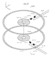
- Fig. 27 is a view illustrating a state that the power reception coupler 320 of Fig. 24 is rotated 90 degrees counterclockwise.
- the through holes 311b, 321b are formed axially symmetrically, electric fields formed by the power transmission coupler 310 and the power reception coupler 320 become axially symmetrical similarly to Fig. 13 and Fig. 14 .
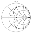
- Fig. 28 illustrates frequency characteristics of transmission efficiency ⁇ 21 and reflection loss ⁇ 11 of the embodiment illustrated in Fig. 27
- Fig. 29 is a smith chart of input impedance S 11.
- the center electrode 311 and the center electrode 321 have the same size and the annular electrode 312 and the annular electrode 322 have the same size, but they may have different sizes.
- the center electrodes 311, 321 and the annular electrodes 312, 322 are completely round, but they may be, for example, elliptic or polygonal.
- the center electrode 311 and the annular electrode 312 and the center electrode 321 and the annular electrode 322 are disposed on the same planes respectively, but for example, they may be disposed to be displaced in an axial direction.
- center electrodes 311, 321 and the annular electrodes 312, 322 may be of curved or bent shape instead of the plate shape, or may be of a three-dimensional shape such as a sphere. Moreover, it may have a three-dimensional shape extended in an axial direction. Further, it may have a three-dimensional shape extended in an axial direction in a state of having cutouts or through holes.
- the inductors 313, 314 reside in both between the connection line 315 and the center electrode 311 and between the connection line 316 and the annular electrode 312, but an inductor may reside in only one of them.
- the inductors 323, 324 reside in both between the connection line 325 and the center electrode 321 and between the connection line 326 and the annular electrode 322, but an inductor may reside in only one of them.
- the inductors are formed by winding conductor lines in a columnar shape, but it may be formed by, for example, one having a shape meandering on a plane as used in a microstrip line, or one having a spiral shape on a plane.
- the above-described embodiments have the circular electrodes and the annular electrodes, but for example, it is also possible to constitute them of cylindrical electrodes as illustrated in Fig. 30 .
- the example of Fig. 30 has a power transmission coupler 410 and a power reception coupler 420.
- electrodes 411, 412 constituting the power transmission coupler 410 are constituted of a conductive member having a cylindrical shape with a radius r1.
- cylindrical members are used in the example of Fig. 30 , it may be formed by curving rectangular conductive members to have a radius r1. In this case, ends of the conductive members may be either in contact or not in contact.
- the electrodes 411, 412 are disposed in parallel at positions separated by a predetermined distance d1 in an axial direction (X direction in the view). Further, a width D of the electrodes 411, 412 including the distance d1 is set to be narrower than a near field indicated by ⁇ /2 ⁇ where the wavelength of electric fields emitted from these electrodes is ⁇ .
- the electrodes 411, 412 are fixed via a not-illustrated insulating member (for example, a dielectric substrate). Further, the electrodes 411, 412 are connected to an alternating-current power supply 417 via inductors 413, 414 and connection lines 415, 416. Note that the power transmission coupler 410 is constituted of the electrodes 411, 412 and the inductors 413, 414.
- Electrodes 421, 422 constituting the power reception coupler 420 are constituted of a conductive member having a cylindrical shape with a radius r2 ( ⁇ r1). Note that although cylindrical members are used in the example of Fig. 30 , it may be formed by curving rectangular conductive members to have a radius r2. In this case, ends of the conductive members may be either in contact or not in contact.
- the electrodes 421, 422 are disposed in parallel at positions separated by a predetermined distance d2 in an axial direction (X direction in the view). Further, the electrodes 421, 422 are disposed so that their center axis corresponds to that of the electrodes 411, 412.
- a width D of the electrodes 421, 422 including the distance d2 is set to be narrower than a near field indicated by ⁇ /2 ⁇ where the wavelength of electric fields emitted from these electrodes 411, 412 is ⁇ .
- the electrodes 421, 422 are fixed via a not-illustrated insulating member (for example, a dielectric substrate). A gap between the electrodes 421, 422 and the electrodes 411, 412 is d3. Further, the electrodes 421, 422 are connected to a load 427 via inductors 423, 424 and connection lines 425, 426.
- the power reception coupler 420 is constituted of the electrodes 421, 422 and the inductors 423, 424.
- a resonance frequency of the resonance circuit constituted of the electrodes 411, 412 and the inductors 413, 414 illustrated in Fig. 30 and a resonance frequency of the resonance circuit constituted of the electrodes 421, 422 and the inductors 423, 424 are set to be the same, and their principle of operation is similar to that of the case of Fig. 1 .
- power can be transmitted efficiently from the power transmission coupler 410 to the power reception coupler 420, and even when the power transmission coupler 410 or the power reception coupler 420 rotates about the center axis, decrease in transmission characteristics is small.
- the electrodes 411, 412, 421, 422 are circular cylinders in Fig.
- the electrodes 411, 412 are structured to be longer in axial direction length than the electrodes 421, 422, but they may be the same, or the electrodes 421, 422 may be structured to be longer in axial direction length than the electrodes 411,412.
Landscapes
- Engineering & Computer Science (AREA)
- Computer Networks & Wireless Communication (AREA)
- Power Engineering (AREA)
- Near-Field Transmission Systems (AREA)
Applications Claiming Priority (2)
| Application Number | Priority Date | Filing Date | Title |
|---|---|---|---|
| JP2013017774A JP6080158B2 (ja) | 2013-01-31 | 2013-01-31 | 無線電力伝送システム |
| PCT/JP2013/081826 WO2014119111A1 (fr) | 2013-01-31 | 2013-11-27 | Système de transmission d'énergie sans fil |
Publications (3)
| Publication Number | Publication Date |
|---|---|
| EP2937972A1 true EP2937972A1 (fr) | 2015-10-28 |
| EP2937972A4 EP2937972A4 (fr) | 2016-10-26 |
| EP2937972B1 EP2937972B1 (fr) | 2019-12-25 |
Family
ID=51261841
Family Applications (1)
| Application Number | Title | Priority Date | Filing Date |
|---|---|---|---|
| EP13873708.5A Active EP2937972B1 (fr) | 2013-01-31 | 2013-11-27 | Système de transmission d'énergie sans fil |
Country Status (4)
| Country | Link |
|---|---|
| US (1) | US10097039B2 (fr) |
| EP (1) | EP2937972B1 (fr) |
| JP (1) | JP6080158B2 (fr) |
| WO (1) | WO2014119111A1 (fr) |
Cited By (1)
| Publication number | Priority date | Publication date | Assignee | Title |
|---|---|---|---|---|
| WO2021213285A1 (fr) * | 2020-04-23 | 2021-10-28 | 深圳市万普拉斯科技有限公司 | Procédé et appareil de détection de décalage de charge sans fil, dispositif électronique et support d'informations |
Families Citing this family (11)
| Publication number | Priority date | Publication date | Assignee | Title |
|---|---|---|---|---|
| WO2014119194A1 (fr) * | 2013-01-31 | 2014-08-07 | 古河電気工業株式会社 | Système de transmission d'énergie sans fil |
| JP6080158B2 (ja) * | 2013-01-31 | 2017-02-15 | 古河電気工業株式会社 | 無線電力伝送システム |
| CA2953621A1 (fr) | 2014-06-26 | 2015-12-30 | Solace Power Inc. | Systeme de transmission de puissance de champ electrique sans fil, emetteur et recepteur pour ce dernier et procede de transfert sans fil de puissance |
| WO2016033697A1 (fr) * | 2014-09-05 | 2016-03-10 | Solace Power Inc. | Système de transfert de puissance de champ électrique sans fil, procédé, émetteur et récepteur associés |
| JP7071142B2 (ja) * | 2018-02-07 | 2022-05-18 | キヤノン株式会社 | 通信システム、通信装置および通信方法 |
| JP2019213427A (ja) * | 2018-06-08 | 2019-12-12 | 福井県 | 脱着容易な高電圧対応のコネクタを備えたバッテリー装置 |
| KR102293809B1 (ko) | 2019-11-13 | 2021-08-26 | 한국과학기술원 | 커패시티브 결합방식의 커플러 구조 및 이를 포함하는 무선전력전송 시스템 |
| KR102374545B1 (ko) * | 2020-05-11 | 2022-03-16 | 주식회사 포스코 | 푸셔 카 레벨러 빔(Pusher Car Leveler Beam)의 가스 유도 장치 |
| CN112217290B (zh) * | 2020-10-15 | 2022-09-20 | 上海科技大学 | 一种用于电容耦合式无线能量传输的交叠型电容耦合器 |
| CN116018741A (zh) * | 2020-10-16 | 2023-04-25 | 国立大学法人东京大学 | 电力传输系统、送电侧装置、受电侧装置、以及无线送电方法 |
| WO2025099731A1 (fr) * | 2023-11-12 | 2025-05-15 | Elssway Ltd. | Système de transfert de puissance sans fil |
Family Cites Families (17)
| Publication number | Priority date | Publication date | Assignee | Title |
|---|---|---|---|---|
| JP3493537B2 (ja) * | 1995-04-10 | 2004-02-03 | オムロン株式会社 | 無線電力伝送装置 |
| JP2004038254A (ja) * | 2002-06-28 | 2004-02-05 | Canon Inc | 無線通信機器及び無線通信方法 |
| JP2004348496A (ja) * | 2003-05-23 | 2004-12-09 | Hitachi Ltd | 通信システム |
| JP4557049B2 (ja) * | 2008-06-09 | 2010-10-06 | ソニー株式会社 | 伝送システム、給電装置、受電装置、及び伝送方法 |
| US8278784B2 (en) * | 2008-07-28 | 2012-10-02 | Qualcomm Incorporated | Wireless power transmission for electronic devices |
| JP5354030B2 (ja) * | 2009-06-25 | 2013-11-27 | 株式会社村田製作所 | 電力伝送システム及び非接触充電装置 |
| CN102804549B (zh) * | 2009-06-25 | 2013-08-21 | 株式会社村田制作所 | 功率传送系统和非接触充电装置 |
| JP2011142724A (ja) * | 2010-01-06 | 2011-07-21 | Hitachi Ltd | 非接触電力伝送装置及びそのための近接場アンテナ |
| JP5348322B2 (ja) * | 2010-05-28 | 2013-11-20 | 株式会社村田製作所 | 電力伝送システム |
| JP5736991B2 (ja) * | 2010-07-22 | 2015-06-17 | Tdk株式会社 | ワイヤレス給電装置およびワイヤレス電力伝送システム |
| JP5777139B2 (ja) * | 2011-02-23 | 2015-09-09 | 株式会社豊田中央研究所 | 車両給電装置及び車両給電方法 |
| WO2013001569A1 (fr) * | 2011-06-28 | 2013-01-03 | Murata Manufacturing Co., Ltd. | Dispositif de puissance haute fréquence, dispositif de transmission de puissance et système de transfert de puissance |
| US20140167525A1 (en) * | 2011-08-16 | 2014-06-19 | Koninklijke Philips N.V. | Techniques for efficient power transfers in a capacitive wireless powering system |
| CN103843228B (zh) * | 2011-10-12 | 2016-07-06 | 株式会社村田制作所 | 无线电力传输系统 |
| WO2013108893A1 (fr) * | 2012-01-18 | 2013-07-25 | 古河電気工業株式会社 | Système de transmission d'électricité sans fil, dispositif de transmission d'électricité et dispositif de réception d'électricité |
| JP5626287B2 (ja) * | 2012-08-02 | 2014-11-19 | トヨタ自動車株式会社 | 非接触送電装置、非接触受電装置、車両および非接触送受電システム |
| JP6080158B2 (ja) * | 2013-01-31 | 2017-02-15 | 古河電気工業株式会社 | 無線電力伝送システム |
-
2013
- 2013-01-31 JP JP2013017774A patent/JP6080158B2/ja active Active
- 2013-11-27 WO PCT/JP2013/081826 patent/WO2014119111A1/fr not_active Ceased
- 2013-11-27 EP EP13873708.5A patent/EP2937972B1/fr active Active
-
2015
- 2015-07-29 US US14/813,074 patent/US10097039B2/en active Active
Cited By (1)
| Publication number | Priority date | Publication date | Assignee | Title |
|---|---|---|---|---|
| WO2021213285A1 (fr) * | 2020-04-23 | 2021-10-28 | 深圳市万普拉斯科技有限公司 | Procédé et appareil de détection de décalage de charge sans fil, dispositif électronique et support d'informations |
Also Published As
| Publication number | Publication date |
|---|---|
| JP2014150649A (ja) | 2014-08-21 |
| EP2937972B1 (fr) | 2019-12-25 |
| US10097039B2 (en) | 2018-10-09 |
| US20150333539A1 (en) | 2015-11-19 |
| EP2937972A4 (fr) | 2016-10-26 |
| WO2014119111A1 (fr) | 2014-08-07 |
| JP6080158B2 (ja) | 2017-02-15 |
Similar Documents
| Publication | Publication Date | Title |
|---|---|---|
| EP2937972B1 (fr) | Système de transmission d'énergie sans fil | |
| EP2953237B1 (fr) | Système de transmission d'énergie sans fil | |
| US9824817B2 (en) | Wireless power transmission system for transmitting power between a power transmitting device and a power receiving device | |
| JP5981202B2 (ja) | 電力伝送システム | |
| CN104637658A (zh) | 非接触式电力传输线圈和非接触式供电装置 | |
| JP2016181755A (ja) | アンテナ装置 | |
| CN103515700A (zh) | 一种rfid天线 | |
| JP5730840B2 (ja) | 無線電力伝送システム、送電装置、および、受電装置 | |
| JP5981203B2 (ja) | 電力伝送システム | |
| JP6301687B2 (ja) | 電力伝送システム | |
| JP6088832B2 (ja) | 無線電力伝送システム | |
| Ohira et al. | Dipole antenna pair revisited from kQ product and Poincare distance for wireless power transfer invited | |
| JP6088814B2 (ja) | 無線電力伝送システム | |
| WO2016114158A1 (fr) | Système de transmission d'énergie sans fil | |
| JP6016654B2 (ja) | 無線電力伝送システム | |
| JP6116924B2 (ja) | 無線電力伝送システム | |
| JP7261517B1 (ja) | インピーダンス変換装置 | |
| JP2022188240A (ja) | 非接触給電装置 | |
| WO2020240895A1 (fr) | Étiquette rfid | |
| JP5461277B2 (ja) | アンテナ装置、送電装置、受電装置および非接触電力伝送システム | |
| JP2022139153A (ja) | 結合共振型無線電力伝送システム | |
| JP2018166390A (ja) | 電力伝送システム |
Legal Events
| Date | Code | Title | Description |
|---|---|---|---|
| PUAI | Public reference made under article 153(3) epc to a published international application that has entered the european phase |
Free format text: ORIGINAL CODE: 0009012 |
|
| 17P | Request for examination filed |
Effective date: 20150724 |
|
| AK | Designated contracting states |
Kind code of ref document: A1 Designated state(s): AL AT BE BG CH CY CZ DE DK EE ES FI FR GB GR HR HU IE IS IT LI LT LU LV MC MK MT NL NO PL PT RO RS SE SI SK SM TR |
|
| AX | Request for extension of the european patent |
Extension state: BA ME |
|
| DAX | Request for extension of the european patent (deleted) | ||
| REG | Reference to a national code |
Ref country code: DE Ref legal event code: R079 Ref document number: 602013064476 Country of ref document: DE Free format text: PREVIOUS MAIN CLASS: H02J0017000000 Ipc: H02J0050050000 |
|
| A4 | Supplementary search report drawn up and despatched |
Effective date: 20160928 |
|
| RIC1 | Information provided on ipc code assigned before grant |
Ipc: H02J 50/05 20160101AFI20160922BHEP |
|
| STAA | Information on the status of an ep patent application or granted ep patent |
Free format text: STATUS: EXAMINATION IS IN PROGRESS |
|
| 17Q | First examination report despatched |
Effective date: 20180828 |
|
| GRAP | Despatch of communication of intention to grant a patent |
Free format text: ORIGINAL CODE: EPIDOSNIGR1 |
|
| STAA | Information on the status of an ep patent application or granted ep patent |
Free format text: STATUS: GRANT OF PATENT IS INTENDED |
|
| INTG | Intention to grant announced |
Effective date: 20190731 |
|
| GRAS | Grant fee paid |
Free format text: ORIGINAL CODE: EPIDOSNIGR3 |
|
| GRAA | (expected) grant |
Free format text: ORIGINAL CODE: 0009210 |
|
| STAA | Information on the status of an ep patent application or granted ep patent |
Free format text: STATUS: THE PATENT HAS BEEN GRANTED |
|
| AK | Designated contracting states |
Kind code of ref document: B1 Designated state(s): AL AT BE BG CH CY CZ DE DK EE ES FI FR GB GR HR HU IE IS IT LI LT LU LV MC MK MT NL NO PL PT RO RS SE SI SK SM TR |
|
| REG | Reference to a national code |
Ref country code: GB Ref legal event code: FG4D |
|
| REG | Reference to a national code |
Ref country code: CH Ref legal event code: EP |
|
| REG | Reference to a national code |
Ref country code: AT Ref legal event code: REF Ref document number: 1218201 Country of ref document: AT Kind code of ref document: T Effective date: 20200115 |
|
| REG | Reference to a national code |
Ref country code: DE Ref legal event code: R096 Ref document number: 602013064476 Country of ref document: DE |
|
| REG | Reference to a national code |
Ref country code: IE Ref legal event code: FG4D |
|
| REG | Reference to a national code |
Ref country code: NL Ref legal event code: MP Effective date: 20191225 |
|
| PG25 | Lapsed in a contracting state [announced via postgrant information from national office to epo] |
Ref country code: SE Free format text: LAPSE BECAUSE OF FAILURE TO SUBMIT A TRANSLATION OF THE DESCRIPTION OR TO PAY THE FEE WITHIN THE PRESCRIBED TIME-LIMIT Effective date: 20191225 Ref country code: LV Free format text: LAPSE BECAUSE OF FAILURE TO SUBMIT A TRANSLATION OF THE DESCRIPTION OR TO PAY THE FEE WITHIN THE PRESCRIBED TIME-LIMIT Effective date: 20191225 Ref country code: GR Free format text: LAPSE BECAUSE OF FAILURE TO SUBMIT A TRANSLATION OF THE DESCRIPTION OR TO PAY THE FEE WITHIN THE PRESCRIBED TIME-LIMIT Effective date: 20200326 Ref country code: NO Free format text: LAPSE BECAUSE OF FAILURE TO SUBMIT A TRANSLATION OF THE DESCRIPTION OR TO PAY THE FEE WITHIN THE PRESCRIBED TIME-LIMIT Effective date: 20200325 Ref country code: BG Free format text: LAPSE BECAUSE OF FAILURE TO SUBMIT A TRANSLATION OF THE DESCRIPTION OR TO PAY THE FEE WITHIN THE PRESCRIBED TIME-LIMIT Effective date: 20200325 Ref country code: LT Free format text: LAPSE BECAUSE OF FAILURE TO SUBMIT A TRANSLATION OF THE DESCRIPTION OR TO PAY THE FEE WITHIN THE PRESCRIBED TIME-LIMIT Effective date: 20191225 Ref country code: FI Free format text: LAPSE BECAUSE OF FAILURE TO SUBMIT A TRANSLATION OF THE DESCRIPTION OR TO PAY THE FEE WITHIN THE PRESCRIBED TIME-LIMIT Effective date: 20191225 |
|
| REG | Reference to a national code |
Ref country code: LT Ref legal event code: MG4D |
|
| PG25 | Lapsed in a contracting state [announced via postgrant information from national office to epo] |
Ref country code: RS Free format text: LAPSE BECAUSE OF FAILURE TO SUBMIT A TRANSLATION OF THE DESCRIPTION OR TO PAY THE FEE WITHIN THE PRESCRIBED TIME-LIMIT Effective date: 20191225 Ref country code: HR Free format text: LAPSE BECAUSE OF FAILURE TO SUBMIT A TRANSLATION OF THE DESCRIPTION OR TO PAY THE FEE WITHIN THE PRESCRIBED TIME-LIMIT Effective date: 20191225 |
|
| PG25 | Lapsed in a contracting state [announced via postgrant information from national office to epo] |
Ref country code: AL Free format text: LAPSE BECAUSE OF FAILURE TO SUBMIT A TRANSLATION OF THE DESCRIPTION OR TO PAY THE FEE WITHIN THE PRESCRIBED TIME-LIMIT Effective date: 20191225 |
|
| PG25 | Lapsed in a contracting state [announced via postgrant information from national office to epo] |
Ref country code: EE Free format text: LAPSE BECAUSE OF FAILURE TO SUBMIT A TRANSLATION OF THE DESCRIPTION OR TO PAY THE FEE WITHIN THE PRESCRIBED TIME-LIMIT Effective date: 20191225 Ref country code: CZ Free format text: LAPSE BECAUSE OF FAILURE TO SUBMIT A TRANSLATION OF THE DESCRIPTION OR TO PAY THE FEE WITHIN THE PRESCRIBED TIME-LIMIT Effective date: 20191225 Ref country code: NL Free format text: LAPSE BECAUSE OF FAILURE TO SUBMIT A TRANSLATION OF THE DESCRIPTION OR TO PAY THE FEE WITHIN THE PRESCRIBED TIME-LIMIT Effective date: 20191225 Ref country code: PT Free format text: LAPSE BECAUSE OF FAILURE TO SUBMIT A TRANSLATION OF THE DESCRIPTION OR TO PAY THE FEE WITHIN THE PRESCRIBED TIME-LIMIT Effective date: 20200520 Ref country code: RO Free format text: LAPSE BECAUSE OF FAILURE TO SUBMIT A TRANSLATION OF THE DESCRIPTION OR TO PAY THE FEE WITHIN THE PRESCRIBED TIME-LIMIT Effective date: 20191225 |
|
| PG25 | Lapsed in a contracting state [announced via postgrant information from national office to epo] |
Ref country code: SM Free format text: LAPSE BECAUSE OF FAILURE TO SUBMIT A TRANSLATION OF THE DESCRIPTION OR TO PAY THE FEE WITHIN THE PRESCRIBED TIME-LIMIT Effective date: 20191225 Ref country code: SK Free format text: LAPSE BECAUSE OF FAILURE TO SUBMIT A TRANSLATION OF THE DESCRIPTION OR TO PAY THE FEE WITHIN THE PRESCRIBED TIME-LIMIT Effective date: 20191225 Ref country code: IS Free format text: LAPSE BECAUSE OF FAILURE TO SUBMIT A TRANSLATION OF THE DESCRIPTION OR TO PAY THE FEE WITHIN THE PRESCRIBED TIME-LIMIT Effective date: 20200425 |
|
| REG | Reference to a national code |
Ref country code: DE Ref legal event code: R097 Ref document number: 602013064476 Country of ref document: DE |
|
| PG25 | Lapsed in a contracting state [announced via postgrant information from national office to epo] |
Ref country code: ES Free format text: LAPSE BECAUSE OF FAILURE TO SUBMIT A TRANSLATION OF THE DESCRIPTION OR TO PAY THE FEE WITHIN THE PRESCRIBED TIME-LIMIT Effective date: 20191225 Ref country code: DK Free format text: LAPSE BECAUSE OF FAILURE TO SUBMIT A TRANSLATION OF THE DESCRIPTION OR TO PAY THE FEE WITHIN THE PRESCRIBED TIME-LIMIT Effective date: 20191225 |
|
| PLBE | No opposition filed within time limit |
Free format text: ORIGINAL CODE: 0009261 |
|
| STAA | Information on the status of an ep patent application or granted ep patent |
Free format text: STATUS: NO OPPOSITION FILED WITHIN TIME LIMIT |
|
| REG | Reference to a national code |
Ref country code: AT Ref legal event code: MK05 Ref document number: 1218201 Country of ref document: AT Kind code of ref document: T Effective date: 20191225 |
|
| PG25 | Lapsed in a contracting state [announced via postgrant information from national office to epo] |
Ref country code: SI Free format text: LAPSE BECAUSE OF FAILURE TO SUBMIT A TRANSLATION OF THE DESCRIPTION OR TO PAY THE FEE WITHIN THE PRESCRIBED TIME-LIMIT Effective date: 20191225 |
|
| 26N | No opposition filed |
Effective date: 20200928 |
|
| PG25 | Lapsed in a contracting state [announced via postgrant information from national office to epo] |
Ref country code: AT Free format text: LAPSE BECAUSE OF FAILURE TO SUBMIT A TRANSLATION OF THE DESCRIPTION OR TO PAY THE FEE WITHIN THE PRESCRIBED TIME-LIMIT Effective date: 20191225 Ref country code: IT Free format text: LAPSE BECAUSE OF FAILURE TO SUBMIT A TRANSLATION OF THE DESCRIPTION OR TO PAY THE FEE WITHIN THE PRESCRIBED TIME-LIMIT Effective date: 20191225 |
|
| PG25 | Lapsed in a contracting state [announced via postgrant information from national office to epo] |
Ref country code: PL Free format text: LAPSE BECAUSE OF FAILURE TO SUBMIT A TRANSLATION OF THE DESCRIPTION OR TO PAY THE FEE WITHIN THE PRESCRIBED TIME-LIMIT Effective date: 20191225 |
|
| PG25 | Lapsed in a contracting state [announced via postgrant information from national office to epo] |
Ref country code: MC Free format text: LAPSE BECAUSE OF FAILURE TO SUBMIT A TRANSLATION OF THE DESCRIPTION OR TO PAY THE FEE WITHIN THE PRESCRIBED TIME-LIMIT Effective date: 20191225 |
|
| REG | Reference to a national code |
Ref country code: CH Ref legal event code: PL |
|
| GBPC | Gb: european patent ceased through non-payment of renewal fee |
Effective date: 20201127 |
|
| PG25 | Lapsed in a contracting state [announced via postgrant information from national office to epo] |
Ref country code: LU Free format text: LAPSE BECAUSE OF NON-PAYMENT OF DUE FEES Effective date: 20201127 |
|
| REG | Reference to a national code |
Ref country code: BE Ref legal event code: MM Effective date: 20201130 |
|
| PG25 | Lapsed in a contracting state [announced via postgrant information from national office to epo] |
Ref country code: LI Free format text: LAPSE BECAUSE OF NON-PAYMENT OF DUE FEES Effective date: 20201130 Ref country code: CH Free format text: LAPSE BECAUSE OF NON-PAYMENT OF DUE FEES Effective date: 20201130 |
|
| PG25 | Lapsed in a contracting state [announced via postgrant information from national office to epo] |
Ref country code: FR Free format text: LAPSE BECAUSE OF NON-PAYMENT OF DUE FEES Effective date: 20201130 Ref country code: IE Free format text: LAPSE BECAUSE OF NON-PAYMENT OF DUE FEES Effective date: 20201127 |
|
| PG25 | Lapsed in a contracting state [announced via postgrant information from national office to epo] |
Ref country code: GB Free format text: LAPSE BECAUSE OF NON-PAYMENT OF DUE FEES Effective date: 20201127 |
|
| PG25 | Lapsed in a contracting state [announced via postgrant information from national office to epo] |
Ref country code: TR Free format text: LAPSE BECAUSE OF FAILURE TO SUBMIT A TRANSLATION OF THE DESCRIPTION OR TO PAY THE FEE WITHIN THE PRESCRIBED TIME-LIMIT Effective date: 20191225 Ref country code: MT Free format text: LAPSE BECAUSE OF FAILURE TO SUBMIT A TRANSLATION OF THE DESCRIPTION OR TO PAY THE FEE WITHIN THE PRESCRIBED TIME-LIMIT Effective date: 20191225 Ref country code: CY Free format text: LAPSE BECAUSE OF FAILURE TO SUBMIT A TRANSLATION OF THE DESCRIPTION OR TO PAY THE FEE WITHIN THE PRESCRIBED TIME-LIMIT Effective date: 20191225 |
|
| PG25 | Lapsed in a contracting state [announced via postgrant information from national office to epo] |
Ref country code: MK Free format text: LAPSE BECAUSE OF FAILURE TO SUBMIT A TRANSLATION OF THE DESCRIPTION OR TO PAY THE FEE WITHIN THE PRESCRIBED TIME-LIMIT Effective date: 20191225 |
|
| PG25 | Lapsed in a contracting state [announced via postgrant information from national office to epo] |
Ref country code: BE Free format text: LAPSE BECAUSE OF NON-PAYMENT OF DUE FEES Effective date: 20201130 |
|
| P01 | Opt-out of the competence of the unified patent court (upc) registered |
Effective date: 20230512 |
|
| PGFP | Annual fee paid to national office [announced via postgrant information from national office to epo] |
Ref country code: DE Payment date: 20250930 Year of fee payment: 13 |