EP2938164A2 - Commande de mode multi-drainage pour une meilleure performance de commande de led - Google Patents
Commande de mode multi-drainage pour une meilleure performance de commande de led Download PDFInfo
- Publication number
- EP2938164A2 EP2938164A2 EP15164422.6A EP15164422A EP2938164A2 EP 2938164 A2 EP2938164 A2 EP 2938164A2 EP 15164422 A EP15164422 A EP 15164422A EP 2938164 A2 EP2938164 A2 EP 2938164A2
- Authority
- EP
- European Patent Office
- Prior art keywords
- bleeder
- bleeder circuit
- circuit
- sense signal
- controller
- Prior art date
- Legal status (The legal status is an assumption and is not a legal conclusion. Google has not performed a legal analysis and makes no representation as to the accuracy of the status listed.)
- Withdrawn
Links
- 230000004044 response Effects 0.000 claims description 46
- 230000001105 regulatory effect Effects 0.000 claims description 12
- 230000007423 decrease Effects 0.000 claims description 11
- 230000004913 activation Effects 0.000 claims description 5
- 230000001965 increasing effect Effects 0.000 claims description 5
- 238000012358 sourcing Methods 0.000 claims description 4
- 230000003247 decreasing effect Effects 0.000 claims description 3
- 230000004397 blinking Effects 0.000 abstract description 3
- 238000000034 method Methods 0.000 description 25
- 230000008569 process Effects 0.000 description 24
- 239000003990 capacitor Substances 0.000 description 11
- 238000001514 detection method Methods 0.000 description 7
- 238000010586 diagram Methods 0.000 description 6
- 238000004891 communication Methods 0.000 description 5
- 238000005516 engineering process Methods 0.000 description 4
- 230000001939 inductive effect Effects 0.000 description 4
- 238000012546 transfer Methods 0.000 description 4
- 238000009966 trimming Methods 0.000 description 4
- 230000001276 controlling effect Effects 0.000 description 3
- 238000003708 edge detection Methods 0.000 description 2
- 230000000694 effects Effects 0.000 description 2
- 238000012986 modification Methods 0.000 description 2
- 230000004048 modification Effects 0.000 description 2
- 238000012545 processing Methods 0.000 description 2
- 239000004065 semiconductor Substances 0.000 description 2
- 230000005669 field effect Effects 0.000 description 1
- 238000001914 filtration Methods 0.000 description 1
- 229910044991 metal oxide Inorganic materials 0.000 description 1
- 150000004706 metal oxides Chemical class 0.000 description 1
- 239000013589 supplement Substances 0.000 description 1
- 230000007704 transition Effects 0.000 description 1
- 230000001960 triggered effect Effects 0.000 description 1
- 230000000007 visual effect Effects 0.000 description 1
Images


Classifications
-
- H—ELECTRICITY
- H05—ELECTRIC TECHNIQUES NOT OTHERWISE PROVIDED FOR
- H05B—ELECTRIC HEATING; ELECTRIC LIGHT SOURCES NOT OTHERWISE PROVIDED FOR; CIRCUIT ARRANGEMENTS FOR ELECTRIC LIGHT SOURCES, IN GENERAL
- H05B45/00—Circuit arrangements for operating light-emitting diodes [LED]
- H05B45/30—Driver circuits
- H05B45/37—Converter circuits
- H05B45/3725—Switched mode power supply [SMPS]
-
- H—ELECTRICITY
- H05—ELECTRIC TECHNIQUES NOT OTHERWISE PROVIDED FOR
- H05B—ELECTRIC HEATING; ELECTRIC LIGHT SOURCES NOT OTHERWISE PROVIDED FOR; CIRCUIT ARRANGEMENTS FOR ELECTRIC LIGHT SOURCES, IN GENERAL
- H05B45/00—Circuit arrangements for operating light-emitting diodes [LED]
- H05B45/10—Controlling the intensity of the light
-
- H—ELECTRICITY
- H05—ELECTRIC TECHNIQUES NOT OTHERWISE PROVIDED FOR
- H05B—ELECTRIC HEATING; ELECTRIC LIGHT SOURCES NOT OTHERWISE PROVIDED FOR; CIRCUIT ARRANGEMENTS FOR ELECTRIC LIGHT SOURCES, IN GENERAL
- H05B45/00—Circuit arrangements for operating light-emitting diodes [LED]
- H05B45/30—Driver circuits
- H05B45/31—Phase-control circuits
-
- H—ELECTRICITY
- H05—ELECTRIC TECHNIQUES NOT OTHERWISE PROVIDED FOR
- H05B—ELECTRIC HEATING; ELECTRIC LIGHT SOURCES NOT OTHERWISE PROVIDED FOR; CIRCUIT ARRANGEMENTS FOR ELECTRIC LIGHT SOURCES, IN GENERAL
- H05B45/00—Circuit arrangements for operating light-emitting diodes [LED]
- H05B45/30—Driver circuits
- H05B45/357—Driver circuits specially adapted for retrofit LED light sources
- H05B45/3574—Emulating the electrical or functional characteristics of incandescent lamps
- H05B45/3575—Emulating the electrical or functional characteristics of incandescent lamps by means of dummy loads or bleeder circuits, e.g. for dimmers
-
- H—ELECTRICITY
- H05—ELECTRIC TECHNIQUES NOT OTHERWISE PROVIDED FOR
- H05B—ELECTRIC HEATING; ELECTRIC LIGHT SOURCES NOT OTHERWISE PROVIDED FOR; CIRCUIT ARRANGEMENTS FOR ELECTRIC LIGHT SOURCES, IN GENERAL
- H05B45/00—Circuit arrangements for operating light-emitting diodes [LED]
- H05B45/50—Circuit arrangements for operating light-emitting diodes [LED] responsive to malfunctions or undesirable behaviour of LEDs; responsive to LED life; Protective circuits
- H05B45/59—Circuit arrangements for operating light-emitting diodes [LED] responsive to malfunctions or undesirable behaviour of LEDs; responsive to LED life; Protective circuits for reducing or suppressing flicker or glow effects
-
- H—ELECTRICITY
- H05—ELECTRIC TECHNIQUES NOT OTHERWISE PROVIDED FOR
- H05B—ELECTRIC HEATING; ELECTRIC LIGHT SOURCES NOT OTHERWISE PROVIDED FOR; CIRCUIT ARRANGEMENTS FOR ELECTRIC LIGHT SOURCES, IN GENERAL
- H05B47/00—Circuit arrangements for operating light sources in general, i.e. where the type of light source is not relevant
- H05B47/10—Controlling the light source
Definitions
- the present disclosure relates generally to circuits for driving light-emitting diodes (LEDs) and, more specifically, to LED driver circuits having phase-angle dimming circuitry.
- LEDs light-emitting diodes
- LED lighting has become popular in the industry due to the many advantages that this technology provides. For example, LED lamps typically have a longer lifespan, pose fewer hazards, and provide increased visual appeal when compared to other lighting technologies, such as compact fluorescent lamp (CFL) or incandescent lighting technologies.
- CFL compact fluorescent lamp
- LED lighting have resulted in LEDs being incorporated into a variety of lighting technologies, televisions, monitors, and other applications.
- phase-angle dimming which may be implemented using either leading-edge or trailing-edge phase-control.
- a Triac circuit is often used to perform this type of phase-angle dimming and operates by delaying the beginning of each half-cycle of alternating current (ac) power or trimming the end of each half-cycle of ac power. By delaying the beginning of each half-cycle or trimming the end of each half-cycle, the amount of power delivered to the load (e.g., the lamp) is reduced, thereby producing a dimming effect in the light output by the lamp.
- Triac dimming circuits work especially well when used to dim incandescent light bulbs since the variations in phase-angle with altered ac line voltages are immaterial to these types of bulbs.
- flicker may be noticed when Triac circuits are used for dimming LED lamps.
- Triac dimming circuits are typically driven by LED drivers having regulated power supplies that provide regulated current and voltage to the LED lamps from ac power lines. Unless the regulated power supplies that drive the LED lamps are designed to recognize and respond to the voltage signals from Triac dimming circuits in a desirable way, the Triac dimming circuits are likely to produce non-ideal results, such as limited dimming range, flickering, blinking, and/or color shifting in the LED lamps.
- Triac dimming circuits with LED lamps is in part due to a characteristic of the Triac itself.
- a Triac is a semiconductor component that behaves as a controlled ac switch.
- the Triac behaves as an open switch to an ac voltage until it receives a trigger signal at a control terminal, causing the switch to close.
- the switch remains closed as long as the current through the switch is above a value referred to as the "holding current.”
- Most incandescent lamps draw more than the minimum holding current from the ac power source to enable reliable and consistent operation of a Triac.
- the comparably low currents drawn by LEDs from efficient power supplies may not meet the minimum holding currents required to keep the Triac switches conducting for reliable operation.
- the Triac may trigger inconsistently.
- a significant ringing may occur whenever the Triac turns on. This ringing may cause even more undesirable behavior as the Triac current may fall to zero and turn off the LED load, resulting in a flickering effect.
- bleeder circuit of the power converter to supplement the current drawn by the LEDs in order to draw a sufficient amount of current to keep the Triac conducting reliably after it is triggered.
- bleeder circuits may typically include passive components and/or active components controlled by a controller or by the converter parameters in response to the load level. While useful to sink additional current, a bleeder circuit that is external to the integrated circuit requires the use of extra components with associated penalties in cost and efficiency.
- phase-dimming LED driver input circuitry having multiple bleeder circuits activated by a controller with multi-bleeder mode control
- the input circuitry may include multiple bleeder circuits controlled by the controller in an open-loop or closed-loop configuration.
- the controller may selectively activate or deactivate the multiple bleeder circuits based on the input line voltage, the dimming state, and the type of dimming being implemented to improve performance of the LED driver by preventing or reducing shimmering/blinking and by reducing bleeder loss.
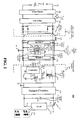
- FIG. 1 shows a general block diagram of an example LED driver system 100 including a regulated converter 140 and a pre-stage Triac dimming circuit 104.
- Triac dimming circuit 104 is coupled to receive an input ac line signal V AC 102 from the input terminals of LED driver system 100 through a fusible protection device 103.
- Triac dimming circuit 104 may apply leading-edge phase control by delaying the beginning of each half-cycle of input ac line signal V AC 102 or may apply trailing-edge phase control by trimming the end of each half-cycle of input ac line signal V AC 102 to produce a phase-controlled ac line/input signal or a phase-controlled Triac signal V Triac 105.
- Triac dimming circuit 104 By removing a portion of each half-cycle of the input ac line signal V AC 102 using Triac dimming circuit 104, the amount of power delivered to the load 175 (e.g., a lamp or LED array 178) is reduced and the light output by the LED appears dimmed.
- the load 175 e.g., a lamp or LED array 1778
- LED driver system 100 may further include bridge rectifier 108 coupled to receive the phase-controlled Triac signal V Triac 105 through the electromagnetic interference (EMI) filter 106.
- EMI electromagnetic interference
- the phase-controlled rectified input voltage V in 111 represented by symbolic waveform 112
- the bridge rectifier 108 has a conduction phase-angle in each half line cycle that is controlled by Triac dimming circuit 104.
- the phase-controlled rectified input voltage V in 111 provides an adjustable average dc voltage to a high frequency regulated converter 140 through input circuitry 138 that, in one example, may include interface devices/blocks, such as input sense/detect circuitry, an inductive and capacitive filter, a damper, and one or more passive/active bleeders with closed-loop or open-loop control depending on the application.
- input circuitry 138 may include interface devices/blocks, such as input sense/detect circuitry, an inductive and capacitive filter, a damper, and one or more passive/active bleeders with closed-loop or open-loop control depending on the application.
- input circuitry 138 may be coupled between the rectifier and phase-controller portion 110 and the converter and output portion 190 of LED driver system 100.
- input circuitry 138 includes multiple-bleeder circuitry 139, which may include multiple bleeder circuits, such as bleeder circuits BLDR-1, 120 and BLDR-2, 130, controlled by control signals, such as signals 125 and 135, generated by Multi-Bleeder Mode Control Integrated Circuit (IC) module 150.
- IC Multi-Bleeder Mode Control Integrated Circuit
- Multi-Bleeder Mode Control IC module 150 may be configured to selectively activate and deactivate the multiple bleeder circuits to adjust the current conducted through closed-loop or open-loop controlled bleeder circuits BLDR-1, 120 and BLDR-2, 130 based on the operation state of the LED driver as determined based on the input sense signals 122 and Dim sense signals 134 (e.g., bleeder current and return current sense signals).
- Multi-Bleeder Mode Control IC module 150 may be referenced to the input ground 101 at terminal 121. It should be appreciated that, in some examples, the Multi-Bleeder Mode Control IC module 150 may be coupled to receive additional signals, such as signals 132, for performing additional features to optimize the performance of the LED driver.
- input circuitry 138 may include other circuit blocks, such as input sense/detect circuitry, an inductive and capacitive filter, a damper, and any number of additional passive/active bleeders with closed-loop or open-loop control depending on the application.
- Regulated converter 140 may be coupled to the output of input circuitry 138 and may be configured to generate a regulated output that, after passing through output circuitry 160 (which may include rectification and filter circuitry) and across output bulk capacitor 168 (which may be used to reduce current ripple through load 175), may include output voltage Vo 170 and/or output current I O 171.
- regulated converter 140 may include a power switch 151 coupled to an energy transfer element 145.
- power switch 151 may include a metal oxide semiconductor field effect transistor (MOSFET) and energy transfer element 145 may include a coupled inductor.
- MOSFET metal oxide semiconductor field effect transistor
- regulated converter 140 may include a controller 155 coupled to control the switching of power switch 151 through a control signal 153 between an ON state (e.g., a state in which current is allowed to conduct) and an OFF state (e.g., a state in which current conduction is prevented) to control the amount of energy transferred from the input to the output of power converter 140 through the coupled inductor of energy transfer element 145.
- Controller 155 may control switching of power switch 151 based on sensed signals, such as current sense signal I D 154 and other feedback or feed forward signals 156 representative of the output or input of LED driver system 100.
- regulated converter 140 may be an isolated (through energy transfer element 145) or non-isolated converter with an output ground 191 that is the same as or different than (e.g., shifted) input ground 101.
- isolated converters include Flyback and forward converters
- non-limiting examples of non-isolated converters include non-isolated Buck-Boost converters, Buck converters, and Tapped Buck converters with a switch and/or an inductor on the return line that may result in an output ground 191 that is level-shifted from the input ground 101.
- FIGs. 2A and 2B illustrate the difference in operation between a bleeder circuit activated by an analog signal response and one activated by an IC controller.
- FIG. 2A illustrates an example input circuitry 200A having a conventional input bleeder 220A activated by damper spike energy reclamation circuitry 230, which is described in greater detail in Applicants' pending U.S. Provisional Patent Application 61/898,883 .
- input bleeder 220A may be coupled to receive rectified voltage V in 211 (represented by symbolic waveform 212), which may correspond to phase-controlled rectified input voltage V in 111.
- Input bleeder 220A may be further coupled to ground 201 and input terminals 239 of converter and output portion 290, which may correspond to converter and output portion 190 of LED driver system 100, through optional capacitive filter 235A and inductive filter 238 (having inductor L, 236 and resistor R, 237).
- Input bleeder 220A may include resistor 221A and capacitor 222A coupled to switch 225A. Switch 225A may be activated through damper resistor 231 via spike energy reclamation.
- leading edge spike current 229 through damper resistor 231 may generate a pulse voltage that charges capacitor 233 through diode 232 and the integrated voltage across capacitor 233 at each switching cycle may be applied to the gate of active bleeder switch 225A through divider resistors 234 and 223.
- Input bleeder 220A may further include Zener component 224 for providing overshoot protection to prevent damage to the gate of switch 225A due to possible over-voltages.
- FIG. 2B illustrates an example input circuitry 200B that may be used to implement input circuitry 138 and that includes an active RC bleeder 220B according to various examples.
- RC bleeder 220B may be coupled to receive rectified voltage V in 211 (represented by symbolic waveform 212) across capacitive filter 235B.
- RC bleeder 220B may be further coupled to ground 201 and input terminals 239 of converter and output portion 290, which may correspond to converter and output portion 190 of LED driver system 100, through inductive filter 238 (having inductor L, 236 and resistor R, 237).
- RC bleeder 220B may include resistor 221B, capacitor 222B, and bleeder active switch 225B, which may be controlled by control signal 226 from Multi-Bleeder Mode Control IC module 250.
- Multi-Bleeder Mode Control IC module 250 may be coupled to receive V DD /Supply 256 and may be referenced to primary ground 201. While only one bleeder circuit is shown, it should be appreciated that input circuitry 200B may include any number of open-loop or closed-loop controlled bleeder circuits and that Multi-Bleeder Mode Control IC module 250 may include additional sense and control terminals to control these additional bleeders.
- input bleeder 220A in FIG.
- switch 225A in which switch 225A is activated by an analog signal response of the spike energy reclamation circuitry 230, switch 225B of bleeder 220B (in FIG. 2B ) is activated in response to a control signal from the controller 250 (e.g., generated based on a preprogrammed algorithm).
- FIG. 3 is a detailed circuit diagram illustrating example input circuitry 300 that may be used to implement input circuitry 138 or 200B.
- the input terminals of input circuitry 300 may be coupled to receive the phase-controlled rectified input voltage V in 311 (represented by symbolic waveform 312), which may correspond to phase-controlled rectified input voltage V in 111 from bridge rectifier 108.
- Input circuitry 300 may further include input capacitor 315 coupled between the input terminals of input circuitry 300 and output capacitor 382 coupled across terminals 339 for filtering noise in phase-controlled rectified input voltage V in 311.
- Input circuitry 300 may further include diode 381 for preventing return current from being conducted from converter and output portion 390 (which may correspond to converter and output portion 190) towards the input of input circuitry 300.
- Input circuitry 300 may further include Zener component 384 having one or more Zener diodes coupled across output capacitor 382 to clamp the voltage at a certain level to prevent damage to the components of input circuitry 300.
- Input circuitry 300 may further include optional filter module 340 having inductor 342 and resistor 344 to act as a differential mode noise filter that may improve performance of the LED driver.
- Input circuitry 300 may further include Multi-Bleeder Mode Control IC module 350 having a V DD /supply terminal 362 coupled to receive a V DD supply that, in one example, may be provided by an RC circuit having resistor R, 361 and capacitor C, 363 coupled between ground 301 and the input rail of the phase-controlled rectified input voltage V in 311.
- Multi-Bleeder Mode Control IC module 350 having a V DD /supply terminal 362 coupled to receive a V DD supply that, in one example, may be provided by an RC circuit having resistor R, 361 and capacitor C, 363 coupled between ground 301 and the input rail of the phase-controlled rectified input voltage V in 311.
- Multi-Bleeder Mode Control IC module 350 may be used to implement Multi-Bleeder Mode Control IC module 150 or Multi-Bleeder Mode Control IC module 250 and may further include a line sense terminal 365 coupled to receive a sense signal representative of phase-controlled rectified input voltage V in 311 (e.g., the instantaneous values for dimmer edge detections) through a resistive divider having resistors 364 and 366.
- V in 311 e.g., the instantaneous values for dimmer edge detections
- Multi-Bleeder Mode Control IC module 350 may be configured to generate any number of desired open-loop and closed-loop activation signals to control multiple bleeders based on the state of operation of the LED driver.
- FIG. 3 illustrates input circuitry 300 for an LED driver having first bleeder BLDR-1, 320 with open-loop control and a second bleeder BLDR-2, 330 with closed-loop control.
- First bleeder BLDR-1, 320 includes resistor R 321, capacitor C, 322, and switch 325
- second bleeder BLDR-2, 330 includes resistor module R Bldr , 331 having any number of parallel and/or series coupled resistors, switching element 335, and sense resistor 336.
- switching element 335 may include a Darlington pair of transistors Q1, 333 and Q2, 334.
- switching element 335 of second bleeder BLDR-2, 330 when switching element 335 of second bleeder BLDR-2, 330 is operating in a closed-loop control to control sinking and/or sourcing current through second bleeder BLDR-2, 330, it may operate in either a linear mode control or a pulse width modulation (PWM) control.
- PWM pulse width modulation
- multi-bleeder mode control IC module 350 linearly controls the activation current to the control terminal of switching element 335 (e.g., the base of transistor Q1, 333, which defines the base current of second transistor Q2 334 of the Darlington pair of transistors of switching element 335).
- switching element 335 may conduct in a linear conduction mode (from an extent of fully ON state to an extent of fully OFF state).
- a linear conduction mode the current through second bleeder BLDR-2, 330 is linearly controlled in a closed-loop in response to bleeder current I Bldr 337 and the return line current I Rtrn 385.
- switching element 335 of second bleeder BLDR-2, 330 may operate in closed-loop PWM control mode to control sinking and/or sourcing current through second bleeder BLDR-2, 330 during each half-line cycle of the phase controlled input voltage.
- the control terminal of switching element 335 may be either pulled up to high line potential of node 345 (through the pull-up resistor 339) to turn the switching element 335 to an ON state or may be pulled down to ground through the internal circuitry of the controller at terminal 332 of multi-bleeder mode control IC module 350 to turn it to an OFF state for a PWM closed-loop current control in second bleeder BLDR-2, 330.
- Sense resistor 336 may be used to provide a bleeder current sense signal representing the current I Bldr 337 conducted through second bleeder BLDR-2, 330 to terminal 338 of Multi-Bleeder Mode Control IC module 350.
- Multi-Bleeder Mode Control IC module 350 may be configured to selectively activate and deactivate the first and second bleeders by outputting open-loop control signal OL-B at terminal 324 and closed-loop control signal CL-B at terminal 332 to control switch 325 of the first bleeder BLDR-1, 320 and switching element 335 of the second bleeder BLDR-2, 330. Additionally, since second bleeder BLDR-2, 330 is a closed-loop controlled bleeder, Multi-Bleeder Mode Control IC module 350 may adjust the amount of current sinked through second bleeder BLDR-2, 330 based on a sensed parameter of the system, such as the load or current drawn by the load.
- Multi-Bleeder Mode Control IC module 350 may increase the bleeder current I Bldr 337 sinked through second bleeder BLDR-2, 330 in response to a decrease in the load or current drawn by the load, and may decrease the bleeder current I Bldr 337 sinked through second bleeder BLDR-2, 330 in response to an increase in the load or current drawn by the load.
- Input circuitry 300 may further include return line current sense resistor 386 for providing a return line current sense signal representing the return line current 385 to terminal 358 of Multi-Bleeder Mode Control IC module 350.
- the return current line sense signal received at terminal 358 may be processed by Multi-Bleeder Mode Control IC module 350 along with the line sense signal received at terminal 365 to selectively activate or deactivate the first and second bleeders.
- Resistor 386 may be positioned at a location on the return line to sense return line current I Rtrn 385, which is summation of LED load return current I LED 383 and second bleeder current I Bldr 337, to allow Multi-Bleeder Mode Control IC module 350 to control return line current I Rtrn 385 and to keep it above a certain threshold.
- positioning resistor 386 in this location to sense and control the return line current I Rtrn 385 e.g., a summation of LED load return current I LED 383 and second bleeder current I Bldr 337) to keep it above the Triac holding current threshold advantageously results in minimizing second bleeder current I Bldr 337 and the possible power dissipation in the closed-loop control of second bleeder BLDR-2, 330 to reduce excess heat generated in resistor module R Bldr , 331.
- Input circuitry 300 may further include diode 387 coupled across resistor 386 to limit the voltage on terminal 358 with reference to ground terminal GND 351.
- the voltage drop across resistor 386 may be limited to the diode forward voltage drop of about 0.7 V.
- Multi-Bleeder Mode Control IC module 350 may include additional terminals 352 for receiving and outputting additional sense and control signals for performing other features to optimize the performance of the LED driver or to control additional bleeder circuits.
- additional terminals 352 for receiving and outputting additional sense and control signals for performing other features to optimize the performance of the LED driver or to control additional bleeder circuits.
- such features have been omitted from the present disclosure.
- FIG. 4 shows an internal block diagram of an example Multi-Bleeder Mode Control IC module 400 that may be used to implement Multi-Bleeder Mode Control IC module 150, 250, or 350.
- Multi-Bleeder Mode Control IC module 400 may include input voltage sense terminal 403 coupled to receive a line sense signal that is representative of a phase-controlled rectified input voltage (e.g., V in 111, 211, or 311 shown in FIGs. 1 , 2A /B, and 3, respectively).
- the line sense signal may be received from a resistor divider (e.g., resistors 364 and 366) coupled to the phase-controlled rectified voltage.
- Multi-Bleeder Mode Control IC module 400 may further include Rectified Input Voltage Level and Edge Detection block 410 coupled to receive the line sense signal from terminal 403 and configured to process the line sense signal to detect a voltage level of the line sense signal and/or a leading or trailing edge in the line sense signal.
- Block 410 may communicate the detected level and/or detected leading or trailing edges with Central Process Unit of Control Logic/Algorithm & Mode Select block 450 via communication signal line 412, which may be a digital or analog signal.
- Central Process Unit of Control Logic/Algorithm & Mode Select block 450 may act as the central processing unit (CPU) of Multi-Bleeder Mode Control IC module 400 and, in some examples, may include a digital processing ASIC unit.
- Multi-Bleeder Mode Control IC module 400 may further include V DD supply terminal 402 coupled to receive supply voltage that, in one example, may be received from an RC circuit (e.g., resistor R, 361 and capacitor C, 363). Terminal 402 may be internally coupled to provide a bias voltage to multiple controller blocks, such as Power-on Reset block 420 that communicates with Central Process Unit of Control Logic/Algorithm & Mode Select block 450 via communication signal line 422 to provide detection signals of the instantaneous input voltage value for the leading-edge or trailing-edge phase control dimming.
- RC circuit e.g., resistor R, 361 and capacitor C, 363
- Terminal 402 may be internally coupled to provide a bias voltage to multiple controller blocks, such as Power-on Reset block 420 that communicates with Central Process Unit of Control Logic/Algorithm & Mode Select block 450 via communication signal line 422 to provide detection signals of the instantaneous input voltage value for the leading-edge or trailing-edge phase
- Terminal 402 may be further coupled to provide a bias voltage to Band Gap and Threshold References block 430, which may provide signal 432 that include band gap and threshold reference voltage signals used in different blocks of Multi-Bleeder Mode Control IC module 400 for the threshold detection of sensed or processed parameters.
- Terminal 402 may be further coupled to provide a bias voltage to Current Reference block 440, which may generate reference current signals I REF 442 that may be used in different blocks of Multi-Bleeder Mode Control IC module 400 for the threshold detection of sensed or processed parameters.
- Terminal 402 may be further coupled to provide voltage V DD 425 to other internal circuitries requiring a bias voltage.
- Multi-Bleeder Mode Control IC module 400 may further include Open-loop control of Bleeder-1 block 480 configured to provide open-loop control signal 486 at OL-B Enable terminal 406 (e.g., terminal 324 in FIG. 3 ) for controlling the switching element of the first bleeder (e.g., switch 325 of the first bleeder BLDR-1, 320).
- Open-loop control of Bleeder-1 block 480 configured to provide open-loop control signal 486 at OL-B Enable terminal 406 (e.g., terminal 324 in FIG. 3 ) for controlling the switching element of the first bleeder (e.g., switch 325 of the first bleeder BLDR-1, 320).
- Open-loop control of Bleeder-1 block 480 may generate control signal 486 based on the communication signals 482 from Central Process Unit of Control Logic/Algorithm & Mode Select block 450, which may be preprogrammed signals generated based on the operational state of the LED driver (e.g., startup/power up mode, no dimming mode, or leading-edge or trailing-edge dimming).
- the operational state of the LED driver e.g., startup/power up mode, no dimming mode, or leading-edge or trailing-edge dimming.
- Multi-Bleeder Mode Control IC module 400 may further include Closed-loop control of Bleeder-2 block 460 configured to provide switching enable signal 467 at CL-B Enable terminal 407 (e.g., terminal 332 in FIG. 3 ) for controlling the switching element of the second bleeder (e.g., switching element 335 of second bleeder BLDR-2, 330).
- CL-B Enable terminal 407 e.g., terminal 332 in FIG. 3
- switching element of the second bleeder e.g., switching element 335 of second bleeder BLDR-2, 330.
- Closed-loop control of Bleeder-2 block 460 may generate switching enable signal 467 using a closed-loop process based on bleeder current sense signal 465 received from terminal 405 (e.g., the current sense signal received at terminal 338) and return current sense 464 received from terminal 404 (e.g., the return current sense signal received at terminal 358), which are referenced to the primary ground reference signal 461 received at terminal 401 (e.g., ground 301 coupled to terminal 351).
- Closed-loop control of Bleeder-2 block 460 may process the received signals (e.g., signals 464 and 465) and communicate with Central Process Unit of Control Logic/Algorithm & Mode Select block 450 via communication signals 462 to enable or disable the switching element of the second bleeder based on the input voltage, dimming status, and dimming type of the LED driver.
- Multi-Bleeder Mode Control IC module 400 may further include System Clock Oscillator block 490 coupled to provide Central Process Unit of Control Logic/Algorithm & Mode Select block 450 with timing sequence signals 492 that may be used by some or all of the internal blocks of Multi-Bleeder Mode Control IC module 400.
- Multi-Bleeder Mode Control IC module 400 may be configured to implement additional features to optimize the performance of the LED driver (which, for the purpose of simplicity, have been omitted from the present disclosure).
- Multi-Bleeder Mode Control IC module 400 may further include one or more Optional signals to LED Driver terminals 408 for outputting additional control signals 478 to implement the additional features.
- These additional control signals 478 may be generated by LED Driver Optional Feature block 470 based on communication signals 472 from Central Process Unit of Control Logic/Algorithm & Mode Select block 450.
- Multi-Bleeder Mode Control IC module 400 may include additional blocks and sense/control terminals for controlling additional open-loop or closed-loop controlled bleeder circuits.
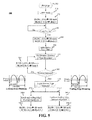
- FIG. 5 is a flow chart illustrating an example process 500 that may be performed by a controller (e.g., 150, 250, 350, or 400) to implement multi-bleeder mode control for an LED driver.
- a controller e.g., 150, 250, 350, or 400
- the LED driver and the multi-bleeder mode controller may power up.
- the multi-bleeder mode controller may enter a power on mode (POR).
- POR power on mode
- two bleeders e.g., those shown in FIGs.
- the controller may cause the first bleeder BLDR-1 (e.g., bleeder 120 or 320) with an open loop (O-L) control to enter an OFF state by outputting a control signal that causes the switch (e.g., switch 325) of the first bleeder BLDR-1 to be in an OFF state. Additionally, at block 520, the controller may cause the second bleeder BLDR-2 with a closed loop (C-L) control (e.g., bleeder 130 or 330) to operate in a first mode.
- C-L closed loop
- the controller may cause the switching element (e.g., switching element 335) of the second bleeder BLDR-2 to be in an ON state (e.g., by allowing terminal 332 to be pulled up to the high line potential of node 345 through the pull-up resistor 339, resulting in the control terminal of switching element 335 also being latched to logic high) for the entire cycle of the phase-controlled rectified input voltage V in .
- the switching element e.g., switching element 335
- the switching element 335 of the second bleeder BLDR-2 may cause the switching element (e.g., switching element 335) of the second bleeder BLDR-2 to be in an ON state (e.g., by allowing terminal 332 to be pulled up to the high line potential of node 345 through the pull-up resistor 339, resulting in the control terminal of switching element 335 also being latched to logic high) for the entire cycle of the phase-controlled rectified input voltage V in .
- the bleeder current I Bldr (e.g., I Bldr 337) through the second bleeder BLDR-2 may have a value of V in /(R BLDR + R SENSE ), where R SENSE is the resistance of the sense resistor (e.g., sense resistor 336) for the current I Bldr through the second bleeder BLDR-2.
- the value of R SENSE may be relatively small compared to the resistance of R BLDR .
- the bleeder current I Bldr may be approximated as V in /R BLDR .
- V DD_th V DD ⁇ V DD_th
- the first bleeder BLDR-1 and second bleeder BLDR-2 may continue to be operated as specified by block 520 while block 530 of process 500 may be repeated until it is determined that the supply voltage V DD is equal to or greater than the threshold value V DD_th .
- process 500 may proceed to block 540 followed by an optional initial delay T DLY (e.g., of about 5ms) at block 550.
- T DLY e.g., of about 5ms
- the controller may cause the first bleeder BLDR-1 to remain in the OFF state by outputting a control signal that causes the switch of the first bleeder BLDR-1 to remain in the OFF state. Additionally, at block 540, the controller may cause the second bleeder BLDR-2 to operate in a second mode. In the second mode, the controller may cause the second bleeder BLDR-2 to remain in an ON state by allowing the switching element of the second bleeder BLDR-2 to be in an ON state (e.g., by allowing terminal 332 to be pulled up to the high line potential of node 345 through the pull up resistor 339, resulting in the control terminal of switching element 335 also being latched to logic high).
- the controller may keep the second bleeder BLDR-2 in the ON state in each cycle of the phase-controlled rectified input voltage V in until either leading-edge dimming is detected (e.g., determined by block 410 in FIG. 4 ) or phase-controlled rectified input voltage V in exceeds a second threshold voltage V Thresh2 (e.g., as determined by block 410 in FIG. 4 ).
- the controller may transition, after a short delay (e.g., about 100us), the operation of the second bleeder BLDR-2 to a closed-loop control in which the bleeder current I Bldr of the second bleeder BLDR-2 based on a sensed parameter of the system, such as the load or current drawn by the load (e.g., the return current sense signal I Rtrn 385).
- a short delay e.g., about 100us
- the controller may cause the bleeder current I Bldr sinked through second bleeder BLDR-2 to increase in response to a decrease in the return current sense signal I Rtrn , and may cause the bleeder current I Bldr sinked through second bleeder BLDR-2 to decrease in response to an increase in the return current sense signal I Rtrn .
- the controller may operate the second bleeder BLDR-2 in a closed-loop in response to the return current sense signal I Rtrn until the phase-controlled rectified input voltage V in decreases below a first voltage threshold V Thresh1 (where V Thresh1 ⁇ V Thresh2 ).
- the controller may then cause the second bleeder BLDR-2 to remain in the ON state until the next cycle of the phase-controlled rectified input voltage V in when the operation of the second mode may be repeated.
- T DLY e.g., of about 5ms
- dimming detection may be performed to determine whether dimming is being applied to the phase-controlled rectified input voltage V in and to determine the type of dimming being applied.
- the process may proceed to block 564 where the controller may cause the first bleeder to remain in the OFF state by outputting a control signal that causes the switch of the first bleeder BLDR-1 to remain in the OFF state. Additionally, at block 564, the controller may operate the second bleeder BLDR-2 in a fourth mode of operation.
- the controller may cause the second bleeder BLDR-2 to be in the OFF state for the entire cycle of phase-controlled rectified input voltage V in by pulling down the voltage at the output terminal (e.g., terminal 332 or 407) of the controller that is coupled to the control terminal of the switching element.
- the current from the high line potential node e.g., node 345
- a pull-up resistor e.g., resistor 339
- Blocks 555, 560, and 564 may continue to be performed until it is determined that dimming is being performed at block 560.
- the process may proceed to block 570.
- the detected dimmer type may be latched or fixed for the remainder of process 500 until an LED driver reset operation is performed, causing the process to return to block 505 where the LED driver and controller are again powered-up.
- Process 500 may then proceed to either the left side (575-L) or right side (575-T) of the flow chart based on whether leading-edge or trailing-edge dimming has been detected. If leading-edge dimming has been detected (represented by the symbolic waveform on the left side of FIG. 5 ), process 500 may proceed to block 580-L where the process may be latched or fixed on the Leading-Edge Bleeder algorithm of block 590-L.
- the controller may cause the first bleeder BLDR-1 to be in the ON state with an open loop (O-L) control by outputting a control signal causing the switch of the first bleeder BLDR-1 to be in the ON state. Additionally, at block 590-L, the controller may operate the second bleeder BLDR-2 in the second mode of operation, discussed above.
- process 500 may instead proceed to block 580-T, where the process may be latched on the Trailing-Edge Bleeder algorithm of block 590-T.
- the controller may cause the first bleeder BLDR-1 with an open loop (O-L) control to be in the OFF state by outputting a control signal that causes the switch of the first bleeder BLDR-1 to be in the OFF state.
- the controller may operate the second bleeder BLDR-2 with a closed loop (C-L) control in a third mode of operation.
- O-L open loop
- C-L closed loop
- the controller may force the second bleeder BLDR-2 into the OFF state at the zero crossing of the phase-controlled rectified input voltage V in by pulling down the voltage at the output terminal (e.g., terminal 332 or 407) of the controller that is coupled to the control terminal of the switching element 335.
- the current from the high line potential node e.g., node 345 may conduct through the pull-up resistor (e.g., resistor 339) to ground inside the controller, thereby preventing the switching element (e.g., switching element 335) from entering the ON state.
- the controller may cause the second bleeder BLDR-2 to be put in the ON state by releasing the pull down (to ground) of the control signal and allowing the control terminal of the switching element (e.g., 335) of the second bleeder BLDR-2 to be latched high through a pull up resistor (e.g., resistor 339).
- a pull up resistor e.g., resistor 339
- the bleeder current I Bldr (e.g., I Bldr 337) through the second bleeder BLDR-2 may be approximated as V in /R BLDR , as discussed above.
- the operation of the third mode may be repeated by the controller causing the second bleeder BLDR-2 to be in the OFF state from the zero crossing of the phase-controlled rectified input voltage V in until either a Tailing-Edge drop is detected or the phase-controlled rectified input voltage V in decreases below the first threshold V Thresh1 .
- control of the second bleeder BLDR-2 may also be placed into the fourth mode of operation in response to a detection of an LED driver fault condition.
- the second bleeder BLDR-2 may be forced into an OFF state for the entire cycle of phase-controlled rectified input voltage V in by pulling down the voltage at the output terminal (e.g., terminal 332 or 407) of the controller that is coupled to the control terminal of the switching element, thereby sinking the current from the high line potential node (e.g., node 345) through a pull-up resistor (e.g., resistor 339) to ground to prevent the switching element from turning ON (closing).
Landscapes
- Circuit Arrangement For Electric Light Sources In General (AREA)
Applications Claiming Priority (1)
| Application Number | Priority Date | Filing Date | Title |
|---|---|---|---|
| US14/261,271 US9402293B2 (en) | 2014-04-24 | 2014-04-24 | Multi-bleeder mode control for improved LED driver performance |
Publications (2)
| Publication Number | Publication Date |
|---|---|
| EP2938164A2 true EP2938164A2 (fr) | 2015-10-28 |
| EP2938164A3 EP2938164A3 (fr) | 2015-12-09 |
Family
ID=53016479
Family Applications (1)
| Application Number | Title | Priority Date | Filing Date |
|---|---|---|---|
| EP15164422.6A Withdrawn EP2938164A3 (fr) | 2014-04-24 | 2015-04-21 | Commande de mode multi-drainage pour une meilleure performance de commande de led |
Country Status (3)
| Country | Link |
|---|---|
| US (1) | US9402293B2 (fr) |
| EP (1) | EP2938164A3 (fr) |
| CN (1) | CN105050237B (fr) |
Cited By (9)
| Publication number | Priority date | Publication date | Assignee | Title |
|---|---|---|---|---|
| CN111031635A (zh) * | 2019-12-27 | 2020-04-17 | 昂宝电子(上海)有限公司 | 用于led照明系统的调光系统及方法 |
| US11183996B2 (en) | 2017-07-10 | 2021-11-23 | On-Bright Electronics (Shanghai) Co., Ltd. | Switch control systems for light emitting diodes and methods thereof |
| US11212885B2 (en) | 2014-04-25 | 2021-12-28 | Guangzhou On-Bright Electronics Co., Ltd. | Systems and methods for intelligent control related to TRIAC dimmers |
| US11224105B2 (en) | 2019-02-19 | 2022-01-11 | On-Bright Electronics (Shanghai) Co., Ltd. | Systems and methods with TRIAC dimmers for voltage conversion related to light emitting diodes |
| US11297704B2 (en) | 2019-08-06 | 2022-04-05 | On-Bright Electronics (Shanghai) Co., Ltd. | Systems and methods for bleeder control related to TRIAC dimmers associated with LED lighting |
| US11405992B2 (en) | 2019-11-20 | 2022-08-02 | On-Bright Electronics (Shanghai) Co., Ltd. | Systems and methods for dimming control related to TRIAC dimmers associated with LED lighting |
| US11540371B2 (en) | 2020-04-13 | 2022-12-27 | On-Bright Electronics (Shanghai) Co., Ltd. | Systems and methods for controlling power factors of LED lighting systems |
| US11564299B2 (en) | 2019-12-19 | 2023-01-24 | On-Bright Electronics (Shanghai) Co., Ltd. | Systems and methods for providing power supply to current controllers associated with LED lighting |
| US11570859B2 (en) | 2017-12-28 | 2023-01-31 | On-Bright Electronics (Shanghai) Co., Ltd. | LED lighting systems with TRIAC dimmers and methods thereof |
Families Citing this family (16)
| Publication number | Priority date | Publication date | Assignee | Title |
|---|---|---|---|---|
| CN103428953B (zh) | 2012-05-17 | 2016-03-16 | 昂宝电子(上海)有限公司 | 用于利用系统控制器进行调光控制的系统和方法 |
| CN103024994B (zh) | 2012-11-12 | 2016-06-01 | 昂宝电子(上海)有限公司 | 使用triac调光器的调光控制系统和方法 |
| CN104066254B (zh) | 2014-07-08 | 2017-01-04 | 昂宝电子(上海)有限公司 | 使用triac调光器进行智能调光控制的系统和方法 |
| KR20160055694A (ko) * | 2014-11-10 | 2016-05-18 | 페어차일드코리아반도체 주식회사 | 대기 전류 공급기 |
| CN105246218A (zh) * | 2015-11-09 | 2016-01-13 | 生迪智慧科技有限公司 | 调光控制电路、调光控制方法及照明设备 |
| CN106413189B (zh) * | 2016-10-17 | 2018-12-28 | 广州昂宝电子有限公司 | 使用调制信号的与triac调光器相关的智能控制系统和方法 |
| CN106793246B (zh) * | 2016-11-16 | 2019-04-02 | 杰华特微电子(杭州)有限公司 | 泄放电路及其控制方法及led控制电路 |
| CN108430128B (zh) * | 2017-02-14 | 2020-05-15 | 朗德万斯公司 | Led灯管及其驱动器电路和受控dc输出电力提供方法 |
| CN107682953A (zh) | 2017-09-14 | 2018-02-09 | 昂宝电子(上海)有限公司 | Led照明系统及其控制方法 |
| CN107995730B (zh) | 2017-11-30 | 2020-01-07 | 昂宝电子(上海)有限公司 | 用于与triac调光器有关的基于阶段的控制的系统和方法 |
| CN110300476B (zh) * | 2018-03-23 | 2022-04-12 | 台达电子工业股份有限公司 | 调光器控制电路、方法以及系统 |
| CN110350647B (zh) * | 2019-06-04 | 2022-01-14 | 漳州科华技术有限责任公司 | Ups反灌能量的泄放方法、泄放装置及终端 |
| US11991802B2 (en) * | 2019-06-14 | 2024-05-21 | Signify Holding B.V. | LED driver control circuit |
| CN110536510B (zh) * | 2019-08-09 | 2022-04-05 | 漳州立达信光电子科技有限公司 | 可控硅调光稳定系统及控制器 |
| CN113325395B (zh) * | 2020-02-28 | 2024-08-27 | 华为技术有限公司 | 一种激光接收电路、一种激光雷达及一种车辆 |
| EP4533906A1 (fr) * | 2022-05-24 | 2025-04-09 | Signify Holding B.V. | Verrou rc d'ampoule connectée optimisé pour une faible puissance de veille |
Family Cites Families (27)
| Publication number | Priority date | Publication date | Assignee | Title |
|---|---|---|---|---|
| JP2005175561A (ja) * | 2003-12-08 | 2005-06-30 | Renesas Technology Corp | 高周波電力増幅回路用電源回路および電源用半導体集積回路並びに電源用電子部品 |
| US7605550B2 (en) * | 2006-07-17 | 2009-10-20 | Microsemi Corp.—Analog Mixed Signal Group Ltd. | Controlled bleeder for power supply |
| US7804256B2 (en) * | 2007-03-12 | 2010-09-28 | Cirrus Logic, Inc. | Power control system for current regulated light sources |
| US7288902B1 (en) * | 2007-03-12 | 2007-10-30 | Cirrus Logic, Inc. | Color variations in a dimmable lighting device with stable color temperature light sources |
| US7696698B2 (en) | 2007-12-31 | 2010-04-13 | Lumination Llc | LEDs tricolor power signal |
| US8212491B2 (en) * | 2008-07-25 | 2012-07-03 | Cirrus Logic, Inc. | Switching power converter control with triac-based leading edge dimmer compatibility |
| TW201134305A (en) * | 2009-07-27 | 2011-10-01 | Koninkl Philips Electronics Nv | Bleeder circuit |
| JP5641180B2 (ja) * | 2009-09-18 | 2014-12-17 | 東芝ライテック株式会社 | Led点灯装置および照明装置 |
| EP2373124B1 (fr) | 2010-04-01 | 2013-10-23 | Rohm Co., Ltd. | Circuit de commande d'un dispositif d'éclairage et son procédé de fonctionnement |
| US9374083B2 (en) * | 2011-03-07 | 2016-06-21 | Rohm Co., Ltd. | Switching current control circuit, LED dimmer system, and LED illumination device |
| TWI461107B (zh) * | 2011-03-22 | 2014-11-11 | Richtek Technology Corp | 發光元件電源供應電路、發光元件驅動電路及其控制方法 |
| JP5828106B2 (ja) * | 2011-04-13 | 2015-12-02 | パナソニックIpマネジメント株式会社 | 固体光源点灯装置およびそれを用いた照明器具 |
| JP5834236B2 (ja) * | 2011-05-12 | 2015-12-16 | パナソニックIpマネジメント株式会社 | 固体光源点灯装置およびそれを用いた照明器具 |
| US8674605B2 (en) * | 2011-05-12 | 2014-03-18 | Osram Sylvania Inc. | Driver circuit for reduced form factor solid state light source lamp |
| TWI441428B (zh) * | 2011-07-06 | 2014-06-11 | Macroblock Inc | 自選維持電流電路 |
| CN104067694B (zh) | 2012-02-02 | 2016-03-30 | 皇家飞利浦有限公司 | Led光源 |
| US9210744B2 (en) * | 2012-04-18 | 2015-12-08 | Power Integrations, Inc. | Bleeder circuit for use in a power supply |
| US20130343090A1 (en) * | 2012-06-21 | 2013-12-26 | Fairchild Korea Semiconductor Ltd. | Active bleeder, active bleeding method, and power supply device where the active bleeder is applied |
| US9590509B2 (en) * | 2012-06-21 | 2017-03-07 | Fairchild Korea Semiconductor Ltd | Power supply device |
| JP2014023225A (ja) * | 2012-07-13 | 2014-02-03 | Toshiba Lighting & Technology Corp | 電源装置、固体発光素子点灯装置および照明装置 |
| US8937435B1 (en) * | 2012-08-27 | 2015-01-20 | Marvell International Ltd. | Diode bridge |
| US9392654B2 (en) * | 2012-08-31 | 2016-07-12 | Marvell World Trade Ltd. | Method and apparatus for controlling a power adjustment to a lighting device |
| RU2638958C2 (ru) * | 2012-11-06 | 2017-12-19 | Филипс Лайтинг Холдинг Б.В. | Схемное устройство и сид лампа, содержащая это схемное устройство |
| US9173258B2 (en) * | 2013-03-14 | 2015-10-27 | Cree, Inc. | Lighting apparatus including a current bleeder module for sinking current during dimming of the lighting apparatus and methods of operating the same |
| US9408261B2 (en) * | 2013-05-07 | 2016-08-02 | Power Integrations, Inc. | Dimmer detector for bleeder circuit activation |
| US9148929B2 (en) * | 2013-07-26 | 2015-09-29 | Lighting Science Group Corporation | LED driver circuit and bleeder circuit |
| US9214851B1 (en) * | 2014-07-02 | 2015-12-15 | Power Integrations, Inc. | Trailing edge detector using current collapse |
-
2014
- 2014-04-24 US US14/261,271 patent/US9402293B2/en not_active Expired - Fee Related
-
2015
- 2015-04-21 EP EP15164422.6A patent/EP2938164A3/fr not_active Withdrawn
- 2015-04-24 CN CN201510201712.4A patent/CN105050237B/zh not_active Expired - Fee Related
Cited By (31)
| Publication number | Priority date | Publication date | Assignee | Title |
|---|---|---|---|---|
| US11212885B2 (en) | 2014-04-25 | 2021-12-28 | Guangzhou On-Bright Electronics Co., Ltd. | Systems and methods for intelligent control related to TRIAC dimmers |
| US11183996B2 (en) | 2017-07-10 | 2021-11-23 | On-Bright Electronics (Shanghai) Co., Ltd. | Switch control systems for light emitting diodes and methods thereof |
| US12438534B2 (en) | 2017-07-10 | 2025-10-07 | On-Bright Electronics (Shanghai) Co., Ltd. | Switch control systems for light emitting diodes and methods thereof |
| US11201612B2 (en) | 2017-07-10 | 2021-12-14 | On-Bright Electronics (Shanghai) Co., Ltd. | Switch control systems for light emitting diodes and methods thereof |
| US11206015B2 (en) | 2017-07-10 | 2021-12-21 | On-Bright Electronics (Shanghai) Co., Ltd. | Switch control systems for light emitting diodes and methods thereof |
| US12009825B2 (en) | 2017-07-10 | 2024-06-11 | On-Bright Electronics (Shanghai) Co., Ltd. | Switch control systems for light emitting diodes and methods thereof |
| US11784638B2 (en) | 2017-07-10 | 2023-10-10 | On-Bright Electronics (Shanghai) Co., Ltd. | Switch control systems for light emitting diodes and methods thereof |
| US11695401B2 (en) | 2017-07-10 | 2023-07-04 | On-Bright Electronics (Shanghai) Co., Ltd. | Switch control systems for light emitting diodes and methods thereof |
| US11570859B2 (en) | 2017-12-28 | 2023-01-31 | On-Bright Electronics (Shanghai) Co., Ltd. | LED lighting systems with TRIAC dimmers and methods thereof |
| US12408243B2 (en) | 2017-12-28 | 2025-09-02 | On-Bright Electronics (Shanghai) Co., Ltd. | LED lighting systems with TRIAC dimmers and methods thereof |
| US11937350B2 (en) | 2017-12-28 | 2024-03-19 | On-Bright Electronics (Shanghai) Co., Ltd. | LED lighting systems with TRIAC dimmers and methods thereof |
| US11638335B2 (en) | 2017-12-28 | 2023-04-25 | On-Bright Electronics (Shanghai) Co., Ltd. | LED lighting systems with TRIAC dimmers and methods thereof |
| US11678417B2 (en) | 2019-02-19 | 2023-06-13 | On-Bright Electronics (Shanghai) Co., Ltd. | Systems and methods with TRIAC dimmers for voltage conversion related to light emitting diodes |
| US11224105B2 (en) | 2019-02-19 | 2022-01-11 | On-Bright Electronics (Shanghai) Co., Ltd. | Systems and methods with TRIAC dimmers for voltage conversion related to light emitting diodes |
| US12193124B2 (en) | 2019-08-06 | 2025-01-07 | On-Bright Electronics (Shanghai) Co., Ltd. | Systems and methods for bleeder control related to TRIAC dimmers associated with LED lighting |
| US11792901B2 (en) | 2019-08-06 | 2023-10-17 | On-Bright Electronics (Shanghai) Co., Ltd. | Systems and methods for bleeder control related to TRIAC dimmers associated with LED lighting |
| US11297704B2 (en) | 2019-08-06 | 2022-04-05 | On-Bright Electronics (Shanghai) Co., Ltd. | Systems and methods for bleeder control related to TRIAC dimmers associated with LED lighting |
| US12089302B2 (en) | 2019-11-20 | 2024-09-10 | On-Bright Electronics (Shanghai) Co., Ltd. | Systems and methods for dimming control related to TRIAC dimmers associated with LED lighting |
| US11743984B2 (en) | 2019-11-20 | 2023-08-29 | On-Bright Electronics (Shanghai) Co., Ltd. | Systems and methods for dimming control related to TRIAC dimmers associated with LED lighting |
| US11405992B2 (en) | 2019-11-20 | 2022-08-02 | On-Bright Electronics (Shanghai) Co., Ltd. | Systems and methods for dimming control related to TRIAC dimmers associated with LED lighting |
| US12464620B2 (en) | 2019-12-19 | 2025-11-04 | On-Bright Electronics (Shanghai) Co., Ltd. | Systems and methods for providing power supply to current controllers associated with LED lighting |
| US11856670B2 (en) | 2019-12-19 | 2023-12-26 | On-Bright Electronics (Shanghai) Co., Ltd. | Systems and methods for providing power supply to current controllers associated with LED lighting |
| US11564299B2 (en) | 2019-12-19 | 2023-01-24 | On-Bright Electronics (Shanghai) Co., Ltd. | Systems and methods for providing power supply to current controllers associated with LED lighting |
| US11252799B2 (en) | 2019-12-27 | 2022-02-15 | On-Bright Electronics (Shanghai) Co., Ltd. | Systems and methods for controlling currents flowing through light emitting diodes |
| US12396079B2 (en) | 2019-12-27 | 2025-08-19 | On-Bright Electronics (Shanghai) Co., Ltd. | Systems and methods for controlling currents flowing through light emitting diodes |
| CN111031635A (zh) * | 2019-12-27 | 2020-04-17 | 昂宝电子(上海)有限公司 | 用于led照明系统的调光系统及方法 |
| CN111031635B (zh) * | 2019-12-27 | 2021-11-30 | 昂宝电子(上海)有限公司 | 用于led照明系统的调光系统及方法 |
| US11723128B2 (en) | 2019-12-27 | 2023-08-08 | On-Bright Electronics (Shanghai) Co., Ltd. | Systems and methods for controlling currents flowing through light emitting diodes |
| US11997772B2 (en) | 2020-04-13 | 2024-05-28 | On-Bright Electronics (Shanghai) Co., Ltd. | Systems and methods for controlling power factors of led lighting systems |
| US11540371B2 (en) | 2020-04-13 | 2022-12-27 | On-Bright Electronics (Shanghai) Co., Ltd. | Systems and methods for controlling power factors of LED lighting systems |
| US12457670B2 (en) | 2020-04-13 | 2025-10-28 | On-Bright Electronics (Shanghai) Co., Ltd. | Systems and methods for controlling power factors of LED lighting systems |
Also Published As
| Publication number | Publication date |
|---|---|
| EP2938164A3 (fr) | 2015-12-09 |
| CN105050237A (zh) | 2015-11-11 |
| US20150312978A1 (en) | 2015-10-29 |
| CN105050237B (zh) | 2019-06-28 |
| US9402293B2 (en) | 2016-07-26 |
Similar Documents
| Publication | Publication Date | Title |
|---|---|---|
| US9402293B2 (en) | Multi-bleeder mode control for improved LED driver performance | |
| US10805997B2 (en) | Methods and apparatus for triac-based dimming of LEDs | |
| US8624514B2 (en) | Feed forward imbalance corrector circuit | |
| US11316421B2 (en) | Apparatus, dimmable light emitting diode driver and control method | |
| US9408261B2 (en) | Dimmer detector for bleeder circuit activation | |
| US9648676B2 (en) | Bleeder circuit emulator for a power converter | |
| US9271352B2 (en) | Line ripple compensation for shimmerless LED driver | |
| US8829819B1 (en) | Enhanced active preload for high performance LED driver with extended dimming | |
| US10433384B2 (en) | LED driver with silicon controlled dimmer, apparatus and control method thereof | |
| US8339055B2 (en) | Inrush current limiter for an LED driver | |
| US20140265898A1 (en) | Lossless preload for led driver with extended dimming | |
| US8427070B2 (en) | Lighting circuit and illumination device | |
| US9332614B2 (en) | LED driver circuit with open load detection | |
| EP3026988A1 (fr) | Commande de convertisseur de puissance avec circuit de courant variable contrôlé analogique | |
| US20130193864A1 (en) | Led dimming circuit for switched dimming | |
| EP2277355A1 (fr) | Circuit de déclenchement de gradateur, système de gradateur et dispositif à gradation réglable | |
| CN102378450A (zh) | Led驱动电路和使用led驱动电路的led照明装置 | |
| CN105657932B (zh) | 光源驱动电路及亮度和色温控制器 | |
| CN106538068A (zh) | 用于调光器电路的过零检测电路 | |
| US20140285099A1 (en) | Power Supply Circuit and Illumination Apparatus | |
| JP5975774B2 (ja) | Led点灯装置 | |
| US9572207B2 (en) | Dimming range extension | |
| KR101027717B1 (ko) | 교류 구동 발광 소자용 조광 보조 장치 및 이를 이용한 조광 장치 | |
| WO2024256323A1 (fr) | Circuit d'attaque de del à limitation de courant d'appel | |
| Kadota et al. | A new bleeder circuit for TRIAC dimmable LED driver based on single-stage topology with a capacitor input rectifier |
Legal Events
| Date | Code | Title | Description |
|---|---|---|---|
| PUAI | Public reference made under article 153(3) epc to a published international application that has entered the european phase |
Free format text: ORIGINAL CODE: 0009012 |
|
| 17P | Request for examination filed |
Effective date: 20150421 |
|
| AK | Designated contracting states |
Kind code of ref document: A2 Designated state(s): AL AT BE BG CH CY CZ DE DK EE ES FI FR GB GR HR HU IE IS IT LI LT LU LV MC MK MT NL NO PL PT RO RS SE SI SK SM TR |
|
| AX | Request for extension of the european patent |
Extension state: BA ME |
|
| PUAL | Search report despatched |
Free format text: ORIGINAL CODE: 0009013 |
|
| AK | Designated contracting states |
Kind code of ref document: A3 Designated state(s): AL AT BE BG CH CY CZ DE DK EE ES FI FR GB GR HR HU IE IS IT LI LT LU LV MC MK MT NL NO PL PT RO RS SE SI SK SM TR |
|
| AX | Request for extension of the european patent |
Extension state: BA ME |
|
| RIC1 | Information provided on ipc code assigned before grant |
Ipc: H05B 37/02 20060101ALI20151104BHEP Ipc: H05B 33/08 20060101AFI20151104BHEP |
|
| 17Q | First examination report despatched |
Effective date: 20151126 |
|
| GRAP | Despatch of communication of intention to grant a patent |
Free format text: ORIGINAL CODE: EPIDOSNIGR1 |
|
| INTG | Intention to grant announced |
Effective date: 20170518 |
|
| STAA | Information on the status of an ep patent application or granted ep patent |
Free format text: STATUS: THE APPLICATION IS DEEMED TO BE WITHDRAWN |
|
| 18D | Application deemed to be withdrawn |
Effective date: 20170929 |