EP2938277B1 - Trocart - Google Patents
Trocart Download PDFInfo
- Publication number
- EP2938277B1 EP2938277B1 EP13867606.9A EP13867606A EP2938277B1 EP 2938277 B1 EP2938277 B1 EP 2938277B1 EP 13867606 A EP13867606 A EP 13867606A EP 2938277 B1 EP2938277 B1 EP 2938277B1
- Authority
- EP
- European Patent Office
- Prior art keywords
- inner hole
- tube portion
- medical device
- end tube
- axis
- Prior art date
- Legal status (The legal status is an assumption and is not a legal conclusion. Google has not performed a legal analysis and makes no representation as to the accuracy of the status listed.)
- Not-in-force
Links
Images





Classifications
-
- A—HUMAN NECESSITIES
- A61—MEDICAL OR VETERINARY SCIENCE; HYGIENE
- A61B—DIAGNOSIS; SURGERY; IDENTIFICATION
- A61B17/00—Surgical instruments, devices or methods
- A61B17/00234—Surgical instruments, devices or methods for minimally invasive surgery
-
- A—HUMAN NECESSITIES
- A61—MEDICAL OR VETERINARY SCIENCE; HYGIENE
- A61B—DIAGNOSIS; SURGERY; IDENTIFICATION
- A61B17/00—Surgical instruments, devices or methods
- A61B17/34—Trocars; Puncturing needles
- A61B17/3417—Details of tips or shafts, e.g. grooves, expandable, bendable; Multiple coaxial sliding cannulas, e.g. for dilating
-
- A—HUMAN NECESSITIES
- A61—MEDICAL OR VETERINARY SCIENCE; HYGIENE
- A61B—DIAGNOSIS; SURGERY; IDENTIFICATION
- A61B17/00—Surgical instruments, devices or methods
- A61B17/34—Trocars; Puncturing needles
- A61B17/3417—Details of tips or shafts, e.g. grooves, expandable, bendable; Multiple coaxial sliding cannulas, e.g. for dilating
- A61B17/3421—Cannulas
-
- A—HUMAN NECESSITIES
- A61—MEDICAL OR VETERINARY SCIENCE; HYGIENE
- A61B—DIAGNOSIS; SURGERY; IDENTIFICATION
- A61B17/00—Surgical instruments, devices or methods
- A61B17/34—Trocars; Puncturing needles
- A61B17/3462—Trocars; Puncturing needles with means for changing the diameter or the orientation of the entrance port of the cannula, e.g. for use with different-sized instruments, reduction ports, adapter seals
-
- A—HUMAN NECESSITIES
- A61—MEDICAL OR VETERINARY SCIENCE; HYGIENE
- A61B—DIAGNOSIS; SURGERY; IDENTIFICATION
- A61B17/00—Surgical instruments, devices or methods
- A61B2017/00017—Electrical control of surgical instruments
- A61B2017/00022—Sensing or detecting at the treatment site
- A61B2017/00075—Motion
-
- A—HUMAN NECESSITIES
- A61—MEDICAL OR VETERINARY SCIENCE; HYGIENE
- A61B—DIAGNOSIS; SURGERY; IDENTIFICATION
- A61B17/00—Surgical instruments, devices or methods
- A61B17/00234—Surgical instruments, devices or methods for minimally invasive surgery
- A61B2017/00292—Surgical instruments, devices or methods for minimally invasive surgery mounted on or guided by flexible, e.g. catheter-like, means
- A61B2017/003—Steerable
- A61B2017/00318—Steering mechanisms
-
- A—HUMAN NECESSITIES
- A61—MEDICAL OR VETERINARY SCIENCE; HYGIENE
- A61B—DIAGNOSIS; SURGERY; IDENTIFICATION
- A61B17/00—Surgical instruments, devices or methods
- A61B2017/00681—Aspects not otherwise provided for
- A61B2017/00738—Aspects not otherwise provided for part of the tool being offset with respect to a main axis, e.g. for better view for the surgeon
-
- A—HUMAN NECESSITIES
- A61—MEDICAL OR VETERINARY SCIENCE; HYGIENE
- A61B—DIAGNOSIS; SURGERY; IDENTIFICATION
- A61B17/00—Surgical instruments, devices or methods
- A61B2017/00831—Material properties
- A61B2017/0084—Material properties low friction
- A61B2017/00845—Material properties low friction of moving parts with respect to each other
-
- A—HUMAN NECESSITIES
- A61—MEDICAL OR VETERINARY SCIENCE; HYGIENE
- A61B—DIAGNOSIS; SURGERY; IDENTIFICATION
- A61B17/00—Surgical instruments, devices or methods
- A61B17/34—Trocars; Puncturing needles
- A61B17/3403—Needle locating or guiding means
- A61B2017/3405—Needle locating or guiding means using mechanical guide means
- A61B2017/3409—Needle locating or guiding means using mechanical guide means including needle or instrument drives
-
- A—HUMAN NECESSITIES
- A61—MEDICAL OR VETERINARY SCIENCE; HYGIENE
- A61B—DIAGNOSIS; SURGERY; IDENTIFICATION
- A61B17/00—Surgical instruments, devices or methods
- A61B17/34—Trocars; Puncturing needles
- A61B17/3417—Details of tips or shafts, e.g. grooves, expandable, bendable; Multiple coaxial sliding cannulas, e.g. for dilating
- A61B17/3421—Cannulas
- A61B2017/3445—Cannulas used as instrument channel for multiple instruments
- A61B2017/3447—Linked multiple cannulas
-
- A—HUMAN NECESSITIES
- A61—MEDICAL OR VETERINARY SCIENCE; HYGIENE
- A61B—DIAGNOSIS; SURGERY; IDENTIFICATION
- A61B17/00—Surgical instruments, devices or methods
- A61B17/34—Trocars; Puncturing needles
- A61B2017/348—Means for supporting the trocar against the body or retaining the trocar inside the body
- A61B2017/3482—Means for supporting the trocar against the body or retaining the trocar inside the body inside
- A61B2017/3484—Anchoring means, e.g. spreading-out umbrella-like structure
- A61B2017/3486—Balloon
-
- A—HUMAN NECESSITIES
- A61—MEDICAL OR VETERINARY SCIENCE; HYGIENE
- A61B—DIAGNOSIS; SURGERY; IDENTIFICATION
- A61B90/00—Instruments, implements or accessories specially adapted for surgery or diagnosis and not covered by any of the groups A61B1/00 - A61B50/00, e.g. for luxation treatment or for protecting wound edges
- A61B90/06—Measuring instruments not otherwise provided for
- A61B2090/062—Measuring instruments not otherwise provided for penetration depth
Definitions
- the present invention relates to trocars.
- a known trocar in the related art is formed of two tube members that are connected so as to be able to swivel relative to each other (for example, see Patent Literature 1).
- This trocar provides a wide working space even when a portion to be treated is located at a shallow position from a body surface, by placing the trocar through the body surface tissue of a patient such that a distal-end tube member is disposed inside the body and a proximal-end tube member is disposed outside the body, and by swiveling the distal-end tube member relative to the proximal-end tube member while a medical device, such as an endoscope, is inserted through the inner hole of the trocar.
- a medical device such as an endoscope
- the medical device needs to be moved in the longitudinal direction or needs to be rotated about the longitudinal axis inside the inner hole of the trocar.
- the present invention is made in view of the above-described circumstances, and an object thereof is to provide a trocar that can ensure a wide working space even when a portion to be treated is located at a shallow position from a body surface, and that can improve the maneuverability.
- An aspect of the present invention is a trocar including the features of claim 1.
- the movement facilitating portion disposed on at least one of the inner surfaces of the first inner hole and second inner hole facilitates the movement of the medical device inside the inner hole, improving the maneuverability thereof. That is, it is easy to move a bent medical device inside a trocar having a bent inner hole.
- the distal-end tube portion and the proximal-end tube portion may be connected such that the axis of the first inner hole and the axis of the second inner hole are inclined relative to each other.
- the medical device outside the body is moved along the axis of the first inner hole in the proximal-end tube portion
- the medical device inside the body is moved in a direction intersecting the axis of the first inner hole, moving along the axis of the second inner hole in the distal-end tube portion.
- the movement facilitating portion facilitates the movement, enabling medical treatment with good maneuverability.
- the distal-end tube portion and the proximal-end tube portion may be connected such that a relative angle formed between the axis of the first inner hole and the axis of the second inner hole can be changed.
- the medical device when the distal-end tube portion is disposed inside the body and the proximal-end tube portion is disposed outside the body, and when the medical device having a flexible portion is inserted into the second inner hole from outside the body, the medical device passes through the first inner hole and the third inner hole and is inserted into the body from the second inner hole, along an axis not parallel to the first inner hole.
- the angle of the distal-end tube portion relative to the proximal-end tube portion By changing the angle of the distal-end tube portion relative to the proximal-end tube portion, a wide working space can be obtained even when a portion to be treated is located at a shallow position from a body surface.
- the movement facilitating portion facilitates the movement of the medical device, enabling treatment with good maneuverability.
- the trocar may include the following elements: a connecting tube portion between the distal-end tube portion and the proximal-end tube portion, the connecting tube portion having a third inner hole communicating with the first inner hole and the second inner hole, wherein the connecting tube portion connects the distal-end tube portion and the proximal-end tube portion such that the axis of the first inner hole and the axis of the second inner hole are kept substantially parallel to each other.
- the insertion direction of the medical device outside the body and the insertion direction of the medical device inside the body becomes parallel.
- the medical device can be operated in the insertion direction which is intended by the operator.
- the shape of the connecting tube portion, in the longitudinal direction of the third inner hole, can be changed.
- the direction in which the medical device extends inside the body can be easily changed while maintaining the substantially parallel relationship between the axis of the first inner hole and the axis of the second inner hole.
- the connecting tube portion may includes a plurality of pieces that are arranged in the longitudinal direction and are connected so as to swivel relative to one another, and an angle-changing means that changes the relative swivel angles between the pieces.
- the shape of the third inner hole in the longitudinal direction can be easily changed by activating the angle-changing means to change the relative swivel angles between the plurality of pieces.
- the movement facilitating portion may be a rollable member rotatably supported on the inner surface.
- the movement facilitating portion includes a movement detecting portion that detects a moving direction of the medical device in the first inner hole or the second inner hole, and an device driving portion that generates motive power in the moving direction of the medical device which is detected by the movement detecting portion so as to facilitate the movement of the medical device.
- the moving direction is detected by the movement detecting portion, and the device driving portion generates motive power in the direction which facilitates the movement.
- the medical device can be more easily moved in the direction in which it is intended to be moved, improving the maneuverability.
- the movement detecting portion may detect the moving direction, in the longitudinal direction, of the medical device inside the first inner hole or the second inner hole.
- the device driving portion may be a driving roller that rotates about an axis intersecting the longitudinal axis of the first inner hole or the second inner hole and that is configured to roll on the outer surface of the medical device.
- the movement detecting portion detects the direction of the movement, and the driving roller is rotated so as to exert motive power in that direction.
- the driving roller is made to roll on the surface of the medical device, and the medical device is driven in the longitudinal direction which is meant by the operator, improving the maneuverability.
- the movement detecting portion may detect the moving direction, about the longitudinal axis, of the medical device inside the first inner hole or the second inner hole
- the device driving portion may be a driving roller that rotates about an axis parallel to the longitudinal axis of the first inner hole or the second inner hole and that is configured to roll on the outer surface of the medical device.
- the movement detecting portion detects the direction of the movement, and the driving roller is rotated so as to exert motive power in that direction.
- the driving roller is made to roll on the surface of the medical device, and the medical device is driven about the longitudinal axis which is meant by the operator, thus improving the maneuverability.
- the present invention provides an advantageous effect of enabling a wide working space even when a portion to be treated is located at a shallow position from the body surface, and improving the maneuverability.
- a trocar 1 according to an embodiment will be described below with reference to the drawings.
- the trocar 1 includes a distal-end tube portion 2, a proximal-end tube portion 3, and a movement facilitating portion 4.
- the distal-end tube portion 2 includes the following elements: a tubular portion 2a that is to be inserted into the body from an opening provided in body surface tissue A of a patient; a flange portion 2b that is provided so as to project radially outward at the proximal-end side of the tubular portion 2a; a balloon 2c that can be inflated and deflated; and a fitting portion 5 to which the proximal-end tube portion 3 is fitted.
- the distal-end side of the tubular portion 2a has such a shape that it is cut obliquely with respect to the axis of the tubular portion 2a, so that it can be easily inserted into the body.
- the tubular portion 2a has a first inner hole 2d penetrating the tubular portion 2a along the longitudinal axis thereof.
- the flange portion 2b is formed larger than the opening provided in the body surface, so, when the tubular portion 2a is inserted into the body, the flange portion 2b comes into contact with the outer surface of the body surface tissue A, as illustrated in FIG. 2 , preventing further insertion.
- the balloon 2c is disposed at a position closer to the distal end than the flange portion 2b.
- the balloon 2c is deflated before being inserted, as illustrated in FIG. 1 , and is inflated after being inserted into the body, as illustrated in FIG. 2 .
- the balloon 2c nips the body surface tissue A together with the flange portion 2b, fixing the distal-end tube portion 2 so as not to be pulled out of the body.
- the fitting portion 5 is disposed at a position closer to the proximal end than the flange portion 2b and has an inner spherical surface 5a that corresponds to a spherical portion 3a of the proximal-end tube portion 3 (described below).
- the outer surface of the fitting portion 5 has an external thread 5b.
- the proximal-end tube portion 3 has a second inner hole 3b penetrating the proximal-end tube portion 3 along the longitudinal axis thereof and has, at the distal-end side, the spherical surface portion 3a that fits into the inner spherical surface 5a of the fitting portion 5 of the distal-end tube portion 2.
- a seal member 6 that can open or close the second inner hole 3b is disposed at the proximal-end side of the proximal-end tube portion 3.
- a spherical bearing is formed, enabling the proximal-end tube portion 3 to freely swivel about the center of the inner spherical surface 5a in any direction relative to the distal-end tube portion 2.
- the movement facilitating portion 4 is formed of a plurality of balls 4a that are rotatably supported on the inner surface of the proximal-end tube portion 3 and the inner surface of the distal-end tube portion 2.
- the plurality of balls 4a are disposed at intervals in the longitudinal direction and the circumferential direction.
- the distal-end tube portion 2 of the trocar 1 is inserted, from the distal-end side, into an opening provided in the body surface tissue A of the patient, with the balloon 2c being deflated.
- the balloon 2c By deflating the balloon 2c, the balloon 2c does not impede the insertion of the distal-end tube portion 2 into the body.
- the balloon 2c is inflated.
- the body surface tissue A is nipped between the flange portion 2b and the balloon 2c, and the distal-end tube portion 2 is securely fixed to the body surface tissue A and is kept fixed to the body surface tissue A so as not to go into the body or be extracted from the body.
- a medical device B is inserted into the second inner hole 3b from an opening at the proximal end of the proximal-end tube portion 3.
- a flexible endoscope serving as the medical device B
- the seal member 6 that has closed the second inner hole 3b is opened. While the medical device B is advanced through the second inner hole 3b and the first inner hole 2d, the seal member 6 keeps the space between the second inner hole 3b and the outer surface of the medical device B sealed.
- the proximal-end tube portion 3 can be swiveled relative to the distal-end tube portion 2 fixed to the body surface tissue A to change the direction of the medical device B extends outside the body to a direction that eases the insertion.
- the medical device B is flexed inside the first inner hole 2d and the second inner hole 3b, and the outer surface thereof is urged against the inner surface of the first inner hole 2d and/or the inner surface of the second inner hole 3b.
- the trocar 1 is provided with the movement facilitating portion 4 formed of the balls 4a that can rotate on the inner surfaces of the first inner hole 2d and the second inner hole 3b, the balls 4a come into contact with the outer surface of the medical device B. Accordingly, it is possible to achieve an advantage in that, when an external force that moves the medical device B in the longitudinal direction is applied to the medical device B or when an external force that rotates the medical device B about the longitudinal axis thereof is applied to the medical device B, the balls 4a are rotated between the outer surface of the medical device B and the inner surface of the first inner hole 2d and/or the inner surface of the second inner hole 3b, as shown in FIG. 4 , reducing the friction between the medical device B and the inner holes 2d and 3b, and improving the maneuverability.
- the movement facilitating portion 4 is not limited thereto, and it may be other rollable members, such as rollers.
- An advantage of using the balls 4a is that, because the balls 4a can rotate in any direction, they can facilitate the movement of the medical device B both in the longitudinal direction and about the longitudinal axis.
- the number and position of the balls 4a may be determined arbitrarily.
- the balls 4a are disposed both in the first inner hole 2d and the second inner hole 3b, the balls 4a may be disposed in only one of them.
- distal-end tube portion 2 and the proximal-end tube portion 3 can be swiveled relative to each other by rotating the spherical portion 3a in the inner spherical surface 5a
- a case where the distal-end tube portion 2 and the proximal-end tube portion 3 are fixed with the axes of the inner holes 2d and 3b being inclined relative to each other can also be employed.
- the medical device B is not limited thereto, and it may be a forceps or the like that has, at a portion in the longitudinal direction, a flexible portion that can transmit pushing and pulling forces and a rotational force.
- the operation of the medical device B is passively facilitated by using the rollable members, such as the balls 4a in this embodiment, instead of this, as illustrated in FIGS. 5 to 8 , a movement facilitating device 7 that actively facilitates the operation of the medical device B may be employed.
- the movement facilitating portion 7 may include a movement detecting portion 8 that detects the movement of the medical device B and an device driving portion 9 that drives the medical device B according to the moving direction of the medical device B detected by the movement detecting portion 8.
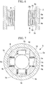
- the movement detecting portion 8 includes the following elements: a casing 8a that is fixed to the inside of the second inner hole 3b in the proximal-end tube portion 3; ring-shaped load sensors 8b that are fixed at both ends, in the longitudinal direction, of the casing 8a; a tubular movable piece 8c to which the medical device B is loosely fitted; a flange-shaped portion 8d that extends radially outward from the middle portion of the movable piece 8c in the longitudinal direction; and two coil springs 8e that are disposed between the flange-shaped portion 8d and the two load sensors 8b.
- the movable piece 8c is supported at substantially the middle position in the longitudinal direction of the casing 8a by the coil springs 8e disposed on both sides of the flange-shaped portion 8d. At this time, the forces generated by the two coil springs 8e are balanced, and the two load sensors 8b detect substantially the same level of load.
- the movable piece 8c that is loosely fitted to the outer surface of the medical device B is moved in the same direction along with the movement of the medical device B, compressing the coil spring 8e disposed in front of the flange-shaped portion 8d in the moving direction and stretching the coil spring 8e disposed behind the flange-shaped portion 8d.
- the two load sensors 8b detect different loads, making it possible to know which direction the medical device B is being moved to.
- the device driving portion 9 includes a casing 9a that is fixed to the inside of the first inner hole 2d in the distal-end tube portion 2, and four rollers 9b and 9c that are rotatably attached to the casing 9a about axes extending in the directions perpendicular to the axis of the first inner hole 2d of the distal-end tube portion 2.
- the four rollers 9b and 9c are disposed at four positions at equal intervals in the circumferential direction of the medical device B.
- rollers 9b and 9c are the driving roller 9b, which is rotated by a motor 9d.
- the remaining three rollers are the driven rollers 9c, which are biased radially inward by springs 9e. That is, the medical device B is biased radially inward by the two driven rollers 9c facing each other, thereby being positioned at the center of the first inner hole 2d in one direction perpendicular to the axis of the first inner hole 2d. Furthermore, the medical device B is biased radially inward by the driven roller 9c facing the driving roller 9b, thereby being positioned at the center of the first inner hole 2d in another direction perpendicular to the axis of the first inner hole 2d.
- the driven roller 9c facing the driving roller 9b biases the medical device B toward the driving roller 9b, the outer surface of the medical device B is pressed against the driving roller 9b.
- the driving force generated by the rotation of the driving roller 9b can be more reliably transmitted to the medical device B.
- the motor 9d for the driving roller 9b is driven to transmit to the medical device B a driving force in the same direction as the moving direction.
- the movement facilitating portion 7 which facilitates the operation of the medical device B when moving the medical device B in the longitudinal direction
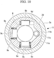
- the operation of the medical device B both in the longitudinal direction and about the longitudinal axis may be facilitated by adding a movement detecting portion 10, as shown in FIG. 9 , and employing an device driving portion 11, as shown in FIG. 10 .
- the movement detecting portion 10 shown in FIG. 9 includes the following elements: a casing 10a that is fixed to the inside of the second inner hole 3b in the proximal-end tube portion 3; two load sensors 10b that are disposed in the casing 10a with a space therebetween in the circumferential direction; a tubular movable piece 10c to which the medical device B is loosely fitted; a projecting portion 10d that extends radially outward from the outer circumferential surface of the movable piece 10c; and two coil springs 10e that are disposed between the projecting portion 10d and the two load sensors 10b.
- the movable piece 10c that is loosely fitted to the outer surface of the medical device B is moved in the same direction along with the movement of the medical device B, compressing the coil spring 10e disposed in front of the projecting portion 10d in the moving direction and stretching the coil spring 10e disposed behind the projecting portion 10d.
- the two load sensors 10b detect different loads, making it possible to know which direction the medical device B is being moved to.
- the device driving portion 11 includes the following elements: a casing 11a that is fixed to the inside of the first inner hole 2d in the distal-end tube portion 2; three rollers 9b and 9c that are attached to the casing 11a so as to be rotatable about axes extending in the directions perpendicular to the axis of the first inner hole 2d of the distal-end tube portion 2; and a roller 11b that is attached so as to be rotatable about an axis parallel to the axis of the first inner hole 2d.
- the roller 11b also serves as a driving roller and is rotated by the motor 11c.
- the remaining three rollers are driven rollers 9c, which are biased radially inward by springs 9e.
- the medical device B is biased radially inward by the driven roller 9c facing the driving roller 11b, thereby being positioned at the center of the first inner hole 2d in the direction perpendicular to the axis of the first inner hole 2d.
- a connecting tube portion 12 that connects the distal-end tube portion 2 and the proximal-end tube portion 3, which are disposed substantially parallel to each other, and that has a third inner hole 12a communicating the first inner hole 2d with the second inner hole 3b may be provided between the distal-end tube portion 2 and the proximal-end tube portion 3.
- a forceps having a flexible portion 13 at one position in the longitudinal direction (hereinbelow, forceps B) is shown as the medical device B.
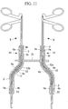
- FIG. 11 shows a case where two trocars 14 are connected by the flange portion 2b.
- This configuration allows the end of the forceps B to be disposed at a position different from the insertion position outside the body, while matching the moving direction of the forceps B on the outside of the body and the moving direction of the forceps B inside the body during the insertion operation.
- the friction which is caused when the forceps B is moved inside the trocar 14 is larger than ones caused according to the above-described embodiments because there are two flexible portions, because the rotatable balls 4a are disposed on the inner surfaces of the distal-end tube portions 2, proximal-end tube portions 3, and connecting tube portions 12, as shown in FIG. 11 , the friction which is caused when the forceps B is moved is reduced, significantly improving the maneuverability.
- the maneuverability can also be improved by providing other rollable members or the above-described movement facilitating portion 7, instead of the balls 4a.
- the two trocars 14 are fixed to the flange portion 2b in FIG. 11 , instead of this, as illustrated in FIG. 12 , the two trocars 14 may be connected to the flange portion 2b so as to be able to swivel about the axis perpendicular to the longitudinal axis.
- This configuration enables the ends of the forceps B inside the body to approach each other, allowing efficient treatment on a diseased part located at a shallow position near the skin tissue A. In such a case, as illustrated in FIG.
- the connecting tube portion 12 may be made flexible.
- the connecting tube portion 12 may have the following elements: a plurality of ring-shaped pieces 15 that can be swiveled relative to each other; a first wire 16 that connects the distal-end tube portion 2 and the proximal-end tube portion 3; a second wire 17 connected to the middle piece 15; and a lever 18 that is operated so as to change the tension of the second wire 17.
- the shape of the connecting tube portion 12 may be changed from the straight-line shape, as shown in FIG. 13 , to a substantially S-shape, as shown in FIG. 14 .
- This configuration also can change the position where the end of the medical device B projects inside the body.
- the connecting tube portion 12 may be bent in a substantially S-shape by one wire 20 via pulleys 19 provided on the middle piece 15, instead of using the two wires 16 and 17.
- the distal-end tube portion 2 and the proximal-end tube portion 3 arranged in a straight-line shape may be bent in two directions with a substantially S shape, as indicated by solid lines and dashed lines in FIG. 16 .
- the reference numeral 24 denotes two wires connecting the distal-end tube portion 2 and the proximal-end tube portion 3.
Landscapes
- Health & Medical Sciences (AREA)
- Surgery (AREA)
- Life Sciences & Earth Sciences (AREA)
- Medical Informatics (AREA)
- Nuclear Medicine, Radiotherapy & Molecular Imaging (AREA)
- Engineering & Computer Science (AREA)
- Biomedical Technology (AREA)
- Heart & Thoracic Surgery (AREA)
- Molecular Biology (AREA)
- Animal Behavior & Ethology (AREA)
- General Health & Medical Sciences (AREA)
- Public Health (AREA)
- Veterinary Medicine (AREA)
- Pathology (AREA)
- Surgical Instruments (AREA)
- Endoscopes (AREA)
Claims (9)
- Trocart (1) comprenant :une partie tube d'extrémité distale (2) qui doit être disposée à l'intérieur d'un corps et a un premier trou interne (2d) à travers lequel un dispositif médical peut passer ; etune partie tube d'extrémité proximale (3) qui doit être disposée à l'extérieur du corps et est reliée à la partie tube d'extrémité distale (2), la partie tube d'extrémité proximale (3) ayant un deuxième trou interne (3b) qui communique avec le premier trou interne (2d) et a un axe qui peut être disposé dans une direction qui n'est pas parallèle à un axe du premier trou interne (2d),caractérisé par :une partie de facilitation de mouvement (4) qui est disposée sur au moins une parmi une surface interne du premier trou interne (2d) et une surfaces interne du deuxième trou interne (3b) pour faciliter le mouvement du dispositif médical à l'intérieur du trou interne,la partie de facilitation de mouvement (4) comprenant une partie de détection de mouvement (8) configurée pour détecter une direction de mouvement du dispositif médical dans le premier trou interne (2d) ou le deuxième trou interne (3b), et une partie d'entraînement de dispositif (9) configurée pour générer une force motrice dans la direction de mouvement du dispositif médical qui est détectée par la partie de détection de mouvement (8) de façon à faciliter le mouvement du dispositif médical.
- Trocart (1) selon la revendication 1, dans lequel la partie tube d'extrémité distale (2) et la partie tube d'extrémité proximale (3) sont reliées de telle sorte que l'axe du premier trou interne (2d) et l'axe du deuxième trou interne (3b) sont inclinés l'un par rapport à l'autre.
- Trocart (1) selon la revendication 1, dans lequel la partie tube d'extrémité distale (2) et la partie tube d'extrémité proximale (3) sont reliées de telle sorte qu'un angle relatif formé entre l'axe du premier trou interne (2d) et l'axe du deuxième trou interne (3b) peut être changé.
- Trocart (1) selon la revendication 1, comprenant une partie tube de liaison (12) entre la partie tube d'extrémité distale (2) et la partie tube d'extrémité proximale (3), la partie tube de liaison (12) ayant un troisième trou interne (12a) communiquant avec le premier trou interne (2d) et le deuxième trou interne (3b),la partie tube de liaison (12) reliant la partie tube d'extrémité distale (2) et la partie tube d'extrémité proximale (3) de telle sorte que l'axe du premier trou interne (2d) et l'axe du deuxième trou interne (3b) sont maintenus sensiblement parallèles l'un à l'autre.
- Trocart (1) selon la revendication 4, dans lequel la forme de la partie tube de liaison (12), dans la direction longitudinale du troisième trou interne (12), peut être changée.
- Trocart (1) selon la revendication 5, dans lequel la partie tube de liaison (12) comprend une pluralité de pièces qui sont disposées dans la direction longitudinale et sont reliées de façon à pivoter les unes par rapport aux autres, et un moyen de changement d'angle configuré pour changer les angles de pivotement relatifs entre les pièces.
- Trocart (1) selon l'une quelconque des revendications 1 à 6, dans lequel la partie de facilitation de mouvement (4) est un élément roulant supporté de manière rotative sur la surface interne.
- Trocart (1) selon la revendication 1, dans lequel :la partie de détection de mouvement (8) est configurée pour détecter la direction de mouvement du dispositif médical à l'intérieur du premier trou interne (2d) ou du deuxième trou interne (3b), la direction de mouvement étant le long de la direction longitudinale, etla partie d'entraînement de dispositif (9) est un rouleau d'entraînement qui est configuré pour tourner autour d'un axe croisant l'axe longitudinal du premier trou interne (2d) ou du deuxième trou interne (3b) et qui est configuré pour rouler sur une surface externe du dispositif médical.
- Trocart (1) selon la revendication 1 ou 8, dans lequel :la partie de détection de mouvement (8) est configurée pour détecter la direction de mouvement du dispositif médical à l'intérieur du premier trou interne (2d) ou du deuxième trou interne (3b), la direction de mouvement étant autour de l'axe longitudinal, etla partie d'entraînement de dispositif (9) est un rouleau d'entraînement qui est configuré pour tourner autour d'un axe parallèle à l'axe longitudinal du premier trou interne (2d) ou du deuxième trou interne (3b) et qui est configuré pour rouler sur une surface externe du dispositif médical.
Applications Claiming Priority (2)
| Application Number | Priority Date | Filing Date | Title |
|---|---|---|---|
| US201261745855P | 2012-12-26 | 2012-12-26 | |
| PCT/JP2013/085332 WO2014104402A1 (fr) | 2012-12-26 | 2013-12-25 | Trocart |
Publications (3)
| Publication Number | Publication Date |
|---|---|
| EP2938277A1 EP2938277A1 (fr) | 2015-11-04 |
| EP2938277A4 EP2938277A4 (fr) | 2016-08-17 |
| EP2938277B1 true EP2938277B1 (fr) | 2017-07-19 |
Family
ID=51021456
Family Applications (1)
| Application Number | Title | Priority Date | Filing Date |
|---|---|---|---|
| EP13867606.9A Not-in-force EP2938277B1 (fr) | 2012-12-26 | 2013-12-25 | Trocart |
Country Status (5)
| Country | Link |
|---|---|
| US (1) | US9962186B2 (fr) |
| EP (1) | EP2938277B1 (fr) |
| JP (1) | JP6023888B2 (fr) |
| CN (1) | CN104853686B (fr) |
| WO (1) | WO2014104402A1 (fr) |
Families Citing this family (16)
| Publication number | Priority date | Publication date | Assignee | Title |
|---|---|---|---|---|
| CN104349734B (zh) * | 2012-05-25 | 2016-09-28 | 富士胶片株式会社 | 内窥镜手术装置及外套管 |
| JP6023872B2 (ja) * | 2013-03-29 | 2016-11-09 | 富士フイルム株式会社 | 内視鏡手術装置 |
| WO2017109788A1 (fr) * | 2015-12-23 | 2017-06-29 | Fidmi Medical Ltd. | Dispositifs et procédés pour accès à un tissu vivant et/ou des lumières et protocoles associés |
| US10702304B2 (en) | 2014-12-23 | 2020-07-07 | Fidmi Medical Ltd. | Devices and methods for ports to living tissue and/or lumens and related procedures |
| JP6353973B2 (ja) * | 2015-03-23 | 2018-07-04 | 富士フイルム株式会社 | 内視鏡用外科手術装置及び外套管 |
| KR20180022944A (ko) * | 2015-07-09 | 2018-03-06 | 카와사키 주코교 카부시키 카이샤 | 수술용 로봇 |
| US10806489B2 (en) * | 2015-07-31 | 2020-10-20 | Purdue Research Foundation | Systems and methods for performing a surgical procedure |
| WO2018235151A1 (fr) * | 2017-06-20 | 2018-12-27 | オリンパス株式会社 | Système de manipulateur médical |
| KR101841456B1 (ko) * | 2017-07-05 | 2018-03-23 | 김창영 | 조직박리용 어셈블리 |
| US10806452B2 (en) * | 2017-08-24 | 2020-10-20 | Covidien Lp | Loading unit for a surgical stapling instrument |
| US10639069B2 (en) * | 2017-09-29 | 2020-05-05 | Ethicon Llc | Radial support assembly for a trocar assembly |
| US10758269B2 (en) * | 2017-09-29 | 2020-09-01 | Ethicon Llc | Compliant deflection devices for trocar assemblies |
| CN209236231U (zh) * | 2018-09-05 | 2019-08-13 | 山东冠龙医疗用品有限公司 | 一种多通道工作套管 |
| US11642185B2 (en) * | 2019-12-16 | 2023-05-09 | Purdue Research Foundation | Systems and methods for performing a surgical procedure |
| US20210196319A1 (en) * | 2019-12-29 | 2021-07-01 | Biosense Webster (Israel) Ltd | Trocar with internal camera providing tilted view angle |
| US11723517B2 (en) * | 2019-12-31 | 2023-08-15 | Biosense Webster (Israel) Ltd. | Wiring of trocar having movable camera and fixed position sensor |
Family Cites Families (20)
| Publication number | Priority date | Publication date | Assignee | Title |
|---|---|---|---|---|
| US4874378A (en) * | 1988-06-01 | 1989-10-17 | Cordis Corporation | Catheter sheath introducer |
| US5407433A (en) * | 1993-02-10 | 1995-04-18 | Origin Medsystems, Inc. | Gas-tight seal accommodating surgical instruments with a wide range of diameters |
| CA2126150C (fr) * | 1993-07-14 | 2005-02-22 | David T. Green | Montage obturateur facilitant l'introduction d'instruments chirurgicaux |
| US5779623A (en) * | 1993-10-08 | 1998-07-14 | Leonard Medical, Inc. | Positioner for medical instruments |
| JPH11276425A (ja) * | 1998-01-27 | 1999-10-12 | Olympus Optical Co Ltd | 内視鏡 |
| DE19815598B4 (de) * | 1998-04-07 | 2007-01-18 | Stm Medizintechnik Starnberg Gmbh | Flexibles Zugangsrohr mit Stülpschlauchsystem |
| US7559893B2 (en) * | 1998-12-01 | 2009-07-14 | Atropos Limited | Wound retractor device |
| US6942671B1 (en) * | 2000-11-06 | 2005-09-13 | Tyco Healthcare Group Lp | Surgical sealing apparatus |
| US7494499B2 (en) | 2002-02-15 | 2009-02-24 | Olympus Corporation | Surgical therapeutic instrument |
| JP4014419B2 (ja) | 2002-02-15 | 2007-11-28 | オリンパス株式会社 | 外科用処置具 |
| AU2003222424A1 (en) * | 2002-05-02 | 2003-11-17 | Medigus Ltd. | Entry port for endoscopes and laparoscopes |
| US20070049966A1 (en) * | 2005-03-22 | 2007-03-01 | Frank Bonadio | Surgical instrument |
| JP4346615B2 (ja) | 2006-03-06 | 2009-10-21 | 株式会社東芝 | 医療用マニピュレータ |
| US8550989B2 (en) * | 2008-02-29 | 2013-10-08 | The University Of Tokyo | Flexibility/rigidity adjustable apparatus |
| JP5191288B2 (ja) | 2008-02-29 | 2013-05-08 | テルモ株式会社 | 塗布具 |
| US20110071541A1 (en) * | 2009-09-23 | 2011-03-24 | Intuitive Surgical, Inc. | Curved cannula |
| CN102711635B (zh) * | 2010-01-15 | 2015-06-10 | 意美森公司 | 用于带有触觉反馈的微创外科手术工具的系统和方法 |
| JP2011172787A (ja) * | 2010-02-25 | 2011-09-08 | Olympus Corp | 外套管 |
| JP5200055B2 (ja) | 2010-05-19 | 2013-05-15 | 足立工業株式会社 | 内視鏡外科手術用鉗子 |
| US20120265214A1 (en) * | 2011-03-10 | 2012-10-18 | Bender Nicholas J | Locking mechanism for deflectable instrument shafts and method of use |
-
2013
- 2013-12-25 JP JP2015527697A patent/JP6023888B2/ja active Active
- 2013-12-25 EP EP13867606.9A patent/EP2938277B1/fr not_active Not-in-force
- 2013-12-25 WO PCT/JP2013/085332 patent/WO2014104402A1/fr not_active Ceased
- 2013-12-25 CN CN201380066161.4A patent/CN104853686B/zh active Active
-
2015
- 2015-05-21 US US14/718,450 patent/US9962186B2/en active Active
Non-Patent Citations (1)
| Title |
|---|
| None * |
Also Published As
| Publication number | Publication date |
|---|---|
| US20150250498A1 (en) | 2015-09-10 |
| US9962186B2 (en) | 2018-05-08 |
| CN104853686A (zh) | 2015-08-19 |
| WO2014104402A1 (fr) | 2014-07-03 |
| JP2015535436A (ja) | 2015-12-14 |
| EP2938277A4 (fr) | 2016-08-17 |
| CN104853686B (zh) | 2017-10-20 |
| EP2938277A1 (fr) | 2015-11-04 |
| JP6023888B2 (ja) | 2016-11-09 |
Similar Documents
| Publication | Publication Date | Title |
|---|---|---|
| US9962186B2 (en) | Trocar | |
| US7955321B2 (en) | Surgical operation apparatus and manipulator for use therein | |
| US8241204B2 (en) | Articulating end cap | |
| CN115153394B (zh) | 一种挠度调节机构、手柄、内窥镜及内窥镜使用方法 | |
| JP2005296412A (ja) | 内視鏡治療装置 | |
| US10343291B2 (en) | Gripping mechanism and gripper | |
| KR20150082243A (ko) | 의료 기기를 위한 자가 길항적 구동 | |
| US20180050456A1 (en) | Grasping mechanism and grasping device | |
| JP6427673B2 (ja) | マニピュレータ | |
| CN107530134A (zh) | 机电手术系统 | |
| JP2009544421A5 (fr) | ||
| JPWO2016136301A1 (ja) | マニピュレータ及びマニピュレータシステム | |
| US11071600B2 (en) | Medical treatment tool and surgical system | |
| WO2011111258A1 (fr) | Dispositif médical doté de plusieurs sections de courbage | |
| EP3173047B1 (fr) | Dispositif de traitement et système de dispositif de traitement | |
| WO2015012044A1 (fr) | Manipulateur thérapeutique et système de manipulateur | |
| JP6600357B2 (ja) | 旋回装置及び医療機器 | |
| EP3305164A1 (fr) | Manipulateur médical | |
| US20170095139A1 (en) | Overtube and manipulator system | |
| CN106231983A (zh) | 处置器具用适配器、内窥镜以及内窥镜系统 | |
| CN103200860A (zh) | 具有横向间隔开的虚拟插入点的单孔腹腔镜进入 | |
| US10786909B2 (en) | Swing mechanism and gripping tool | |
| CN216382432U (zh) | 传动机构、机械臂及手术机器人 | |
| KR20140134360A (ko) | 수술용 장치 및 이를 구비하는 수술용 로봇 | |
| US20150112362A1 (en) | Medical manipulator |
Legal Events
| Date | Code | Title | Description |
|---|---|---|---|
| PUAI | Public reference made under article 153(3) epc to a published international application that has entered the european phase |
Free format text: ORIGINAL CODE: 0009012 |
|
| 17P | Request for examination filed |
Effective date: 20150721 |
|
| AK | Designated contracting states |
Kind code of ref document: A1 Designated state(s): AL AT BE BG CH CY CZ DE DK EE ES FI FR GB GR HR HU IE IS IT LI LT LU LV MC MK MT NL NO PL PT RO RS SE SI SK SM TR |
|
| AX | Request for extension of the european patent |
Extension state: BA ME |
|
| DAX | Request for extension of the european patent (deleted) | ||
| A4 | Supplementary search report drawn up and despatched |
Effective date: 20160715 |
|
| RIC1 | Information provided on ipc code assigned before grant |
Ipc: A61B 17/34 20060101AFI20160712BHEP |
|
| RAP1 | Party data changed (applicant data changed or rights of an application transferred) |
Owner name: OLYMPUS CORPORATION |
|
| RIN1 | Information on inventor provided before grant (corrected) |
Inventor name: KOBAYASHI, HIROYOSHI Inventor name: IKEDA, HIROMU Inventor name: KIKUCHI, SATORU Inventor name: MIYAZAKI, YASUHIRO Inventor name: HARAGUCHI, MASAFUMI |
|
| RAP1 | Party data changed (applicant data changed or rights of an application transferred) |
Owner name: OLYMPUS CORPORATION |
|
| RIN1 | Information on inventor provided before grant (corrected) |
Inventor name: KOBAYASHI, HIROYOSHI Inventor name: IKEDA, HIROMU Inventor name: MIYAZAKI, YASUHIRO Inventor name: KIKUCHI, SATORU Inventor name: HARAGUCHI, MASAFUMI |
|
| GRAJ | Information related to disapproval of communication of intention to grant by the applicant or resumption of examination proceedings by the epo deleted |
Free format text: ORIGINAL CODE: EPIDOSDIGR1 |
|
| STAA | Information on the status of an ep patent application or granted ep patent |
Free format text: STATUS: GRANT OF PATENT IS INTENDED |
|
| GRAP | Despatch of communication of intention to grant a patent |
Free format text: ORIGINAL CODE: EPIDOSNIGR1 |
|
| INTG | Intention to grant announced |
Effective date: 20170210 |
|
| GRAS | Grant fee paid |
Free format text: ORIGINAL CODE: EPIDOSNIGR3 |
|
| GRAA | (expected) grant |
Free format text: ORIGINAL CODE: 0009210 |
|
| STAA | Information on the status of an ep patent application or granted ep patent |
Free format text: STATUS: THE PATENT HAS BEEN GRANTED |
|
| AK | Designated contracting states |
Kind code of ref document: B1 Designated state(s): AL AT BE BG CH CY CZ DE DK EE ES FI FR GB GR HR HU IE IS IT LI LT LU LV MC MK MT NL NO PL PT RO RS SE SI SK SM TR |
|
| REG | Reference to a national code |
Ref country code: GB Ref legal event code: FG4D |
|
| REG | Reference to a national code |
Ref country code: CH Ref legal event code: EP |
|
| REG | Reference to a national code |
Ref country code: IE Ref legal event code: FG4D |
|
| REG | Reference to a national code |
Ref country code: AT Ref legal event code: REF Ref document number: 909595 Country of ref document: AT Kind code of ref document: T Effective date: 20170815 |
|
| REG | Reference to a national code |
Ref country code: DE Ref legal event code: R096 Ref document number: 602013023911 Country of ref document: DE |
|
| REG | Reference to a national code |
Ref country code: NL Ref legal event code: MP Effective date: 20170719 |
|
| REG | Reference to a national code |
Ref country code: LT Ref legal event code: MG4D |
|
| REG | Reference to a national code |
Ref country code: AT Ref legal event code: MK05 Ref document number: 909595 Country of ref document: AT Kind code of ref document: T Effective date: 20170719 |
|
| PG25 | Lapsed in a contracting state [announced via postgrant information from national office to epo] |
Ref country code: HR Free format text: LAPSE BECAUSE OF FAILURE TO SUBMIT A TRANSLATION OF THE DESCRIPTION OR TO PAY THE FEE WITHIN THE PRESCRIBED TIME-LIMIT Effective date: 20170719 Ref country code: LT Free format text: LAPSE BECAUSE OF FAILURE TO SUBMIT A TRANSLATION OF THE DESCRIPTION OR TO PAY THE FEE WITHIN THE PRESCRIBED TIME-LIMIT Effective date: 20170719 Ref country code: SE Free format text: LAPSE BECAUSE OF FAILURE TO SUBMIT A TRANSLATION OF THE DESCRIPTION OR TO PAY THE FEE WITHIN THE PRESCRIBED TIME-LIMIT Effective date: 20170719 Ref country code: AT Free format text: LAPSE BECAUSE OF FAILURE TO SUBMIT A TRANSLATION OF THE DESCRIPTION OR TO PAY THE FEE WITHIN THE PRESCRIBED TIME-LIMIT Effective date: 20170719 Ref country code: NO Free format text: LAPSE BECAUSE OF FAILURE TO SUBMIT A TRANSLATION OF THE DESCRIPTION OR TO PAY THE FEE WITHIN THE PRESCRIBED TIME-LIMIT Effective date: 20171019 Ref country code: FI Free format text: LAPSE BECAUSE OF FAILURE TO SUBMIT A TRANSLATION OF THE DESCRIPTION OR TO PAY THE FEE WITHIN THE PRESCRIBED TIME-LIMIT Effective date: 20170719 Ref country code: NL Free format text: LAPSE BECAUSE OF FAILURE TO SUBMIT A TRANSLATION OF THE DESCRIPTION OR TO PAY THE FEE WITHIN THE PRESCRIBED TIME-LIMIT Effective date: 20170719 |
|
| PG25 | Lapsed in a contracting state [announced via postgrant information from national office to epo] |
Ref country code: ES Free format text: LAPSE BECAUSE OF FAILURE TO SUBMIT A TRANSLATION OF THE DESCRIPTION OR TO PAY THE FEE WITHIN THE PRESCRIBED TIME-LIMIT Effective date: 20170719 Ref country code: LV Free format text: LAPSE BECAUSE OF FAILURE TO SUBMIT A TRANSLATION OF THE DESCRIPTION OR TO PAY THE FEE WITHIN THE PRESCRIBED TIME-LIMIT Effective date: 20170719 Ref country code: IS Free format text: LAPSE BECAUSE OF FAILURE TO SUBMIT A TRANSLATION OF THE DESCRIPTION OR TO PAY THE FEE WITHIN THE PRESCRIBED TIME-LIMIT Effective date: 20171119 Ref country code: GR Free format text: LAPSE BECAUSE OF FAILURE TO SUBMIT A TRANSLATION OF THE DESCRIPTION OR TO PAY THE FEE WITHIN THE PRESCRIBED TIME-LIMIT Effective date: 20171020 Ref country code: BG Free format text: LAPSE BECAUSE OF FAILURE TO SUBMIT A TRANSLATION OF THE DESCRIPTION OR TO PAY THE FEE WITHIN THE PRESCRIBED TIME-LIMIT Effective date: 20171019 Ref country code: RS Free format text: LAPSE BECAUSE OF FAILURE TO SUBMIT A TRANSLATION OF THE DESCRIPTION OR TO PAY THE FEE WITHIN THE PRESCRIBED TIME-LIMIT Effective date: 20170719 Ref country code: PL Free format text: LAPSE BECAUSE OF FAILURE TO SUBMIT A TRANSLATION OF THE DESCRIPTION OR TO PAY THE FEE WITHIN THE PRESCRIBED TIME-LIMIT Effective date: 20170719 |
|
| REG | Reference to a national code |
Ref country code: DE Ref legal event code: R097 Ref document number: 602013023911 Country of ref document: DE |
|
| PG25 | Lapsed in a contracting state [announced via postgrant information from national office to epo] |
Ref country code: RO Free format text: LAPSE BECAUSE OF FAILURE TO SUBMIT A TRANSLATION OF THE DESCRIPTION OR TO PAY THE FEE WITHIN THE PRESCRIBED TIME-LIMIT Effective date: 20170719 Ref country code: DK Free format text: LAPSE BECAUSE OF FAILURE TO SUBMIT A TRANSLATION OF THE DESCRIPTION OR TO PAY THE FEE WITHIN THE PRESCRIBED TIME-LIMIT Effective date: 20170719 Ref country code: CZ Free format text: LAPSE BECAUSE OF FAILURE TO SUBMIT A TRANSLATION OF THE DESCRIPTION OR TO PAY THE FEE WITHIN THE PRESCRIBED TIME-LIMIT Effective date: 20170719 |
|
| PLBE | No opposition filed within time limit |
Free format text: ORIGINAL CODE: 0009261 |
|
| STAA | Information on the status of an ep patent application or granted ep patent |
Free format text: STATUS: NO OPPOSITION FILED WITHIN TIME LIMIT |
|
| PG25 | Lapsed in a contracting state [announced via postgrant information from national office to epo] |
Ref country code: IT Free format text: LAPSE BECAUSE OF FAILURE TO SUBMIT A TRANSLATION OF THE DESCRIPTION OR TO PAY THE FEE WITHIN THE PRESCRIBED TIME-LIMIT Effective date: 20170719 Ref country code: EE Free format text: LAPSE BECAUSE OF FAILURE TO SUBMIT A TRANSLATION OF THE DESCRIPTION OR TO PAY THE FEE WITHIN THE PRESCRIBED TIME-LIMIT Effective date: 20170719 Ref country code: SK Free format text: LAPSE BECAUSE OF FAILURE TO SUBMIT A TRANSLATION OF THE DESCRIPTION OR TO PAY THE FEE WITHIN THE PRESCRIBED TIME-LIMIT Effective date: 20170719 Ref country code: SM Free format text: LAPSE BECAUSE OF FAILURE TO SUBMIT A TRANSLATION OF THE DESCRIPTION OR TO PAY THE FEE WITHIN THE PRESCRIBED TIME-LIMIT Effective date: 20170719 |
|
| 26N | No opposition filed |
Effective date: 20180420 |
|
| REG | Reference to a national code |
Ref country code: CH Ref legal event code: PL |
|
| GBPC | Gb: european patent ceased through non-payment of renewal fee |
Effective date: 20171225 |
|
| PG25 | Lapsed in a contracting state [announced via postgrant information from national office to epo] |
Ref country code: SI Free format text: LAPSE BECAUSE OF FAILURE TO SUBMIT A TRANSLATION OF THE DESCRIPTION OR TO PAY THE FEE WITHIN THE PRESCRIBED TIME-LIMIT Effective date: 20170719 |
|
| REG | Reference to a national code |
Ref country code: IE Ref legal event code: MM4A |
|
| PG25 | Lapsed in a contracting state [announced via postgrant information from national office to epo] |
Ref country code: LU Free format text: LAPSE BECAUSE OF NON-PAYMENT OF DUE FEES Effective date: 20171225 Ref country code: MT Free format text: LAPSE BECAUSE OF NON-PAYMENT OF DUE FEES Effective date: 20171225 |
|
| REG | Reference to a national code |
Ref country code: FR Ref legal event code: ST Effective date: 20180831 |
|
| REG | Reference to a national code |
Ref country code: BE Ref legal event code: MM Effective date: 20171231 |
|
| PG25 | Lapsed in a contracting state [announced via postgrant information from national office to epo] |
Ref country code: FR Free format text: LAPSE BECAUSE OF NON-PAYMENT OF DUE FEES Effective date: 20180102 Ref country code: IE Free format text: LAPSE BECAUSE OF NON-PAYMENT OF DUE FEES Effective date: 20171225 |
|
| PG25 | Lapsed in a contracting state [announced via postgrant information from national office to epo] |
Ref country code: CH Free format text: LAPSE BECAUSE OF NON-PAYMENT OF DUE FEES Effective date: 20171231 Ref country code: GB Free format text: LAPSE BECAUSE OF NON-PAYMENT OF DUE FEES Effective date: 20171225 Ref country code: LI Free format text: LAPSE BECAUSE OF NON-PAYMENT OF DUE FEES Effective date: 20171231 Ref country code: BE Free format text: LAPSE BECAUSE OF NON-PAYMENT OF DUE FEES Effective date: 20171231 |
|
| PGFP | Annual fee paid to national office [announced via postgrant information from national office to epo] |
Ref country code: DE Payment date: 20181210 Year of fee payment: 6 |
|
| PG25 | Lapsed in a contracting state [announced via postgrant information from national office to epo] |
Ref country code: MC Free format text: LAPSE BECAUSE OF FAILURE TO SUBMIT A TRANSLATION OF THE DESCRIPTION OR TO PAY THE FEE WITHIN THE PRESCRIBED TIME-LIMIT Effective date: 20170719 Ref country code: HU Free format text: LAPSE BECAUSE OF FAILURE TO SUBMIT A TRANSLATION OF THE DESCRIPTION OR TO PAY THE FEE WITHIN THE PRESCRIBED TIME-LIMIT; INVALID AB INITIO Effective date: 20131225 |
|
| PG25 | Lapsed in a contracting state [announced via postgrant information from national office to epo] |
Ref country code: CY Free format text: LAPSE BECAUSE OF FAILURE TO SUBMIT A TRANSLATION OF THE DESCRIPTION OR TO PAY THE FEE WITHIN THE PRESCRIBED TIME-LIMIT Effective date: 20170719 |
|
| PG25 | Lapsed in a contracting state [announced via postgrant information from national office to epo] |
Ref country code: MK Free format text: LAPSE BECAUSE OF FAILURE TO SUBMIT A TRANSLATION OF THE DESCRIPTION OR TO PAY THE FEE WITHIN THE PRESCRIBED TIME-LIMIT Effective date: 20170719 |
|
| PG25 | Lapsed in a contracting state [announced via postgrant information from national office to epo] |
Ref country code: TR Free format text: LAPSE BECAUSE OF FAILURE TO SUBMIT A TRANSLATION OF THE DESCRIPTION OR TO PAY THE FEE WITHIN THE PRESCRIBED TIME-LIMIT Effective date: 20170719 |
|
| PG25 | Lapsed in a contracting state [announced via postgrant information from national office to epo] |
Ref country code: PT Free format text: LAPSE BECAUSE OF FAILURE TO SUBMIT A TRANSLATION OF THE DESCRIPTION OR TO PAY THE FEE WITHIN THE PRESCRIBED TIME-LIMIT Effective date: 20170719 |
|
| REG | Reference to a national code |
Ref country code: DE Ref legal event code: R119 Ref document number: 602013023911 Country of ref document: DE |
|
| PG25 | Lapsed in a contracting state [announced via postgrant information from national office to epo] |
Ref country code: AL Free format text: LAPSE BECAUSE OF FAILURE TO SUBMIT A TRANSLATION OF THE DESCRIPTION OR TO PAY THE FEE WITHIN THE PRESCRIBED TIME-LIMIT Effective date: 20170719 |
|
| PG25 | Lapsed in a contracting state [announced via postgrant information from national office to epo] |
Ref country code: DE Free format text: LAPSE BECAUSE OF NON-PAYMENT OF DUE FEES Effective date: 20200701 |