EP2938437B1 - Vorrichtung zur steuerung der ladung nach einer aerosolsentladung - Google Patents
Vorrichtung zur steuerung der ladung nach einer aerosolsentladung Download PDFInfo
- Publication number
- EP2938437B1 EP2938437B1 EP13821485.3A EP13821485A EP2938437B1 EP 2938437 B1 EP2938437 B1 EP 2938437B1 EP 13821485 A EP13821485 A EP 13821485A EP 2938437 B1 EP2938437 B1 EP 2938437B1
- Authority
- EP
- European Patent Office
- Prior art keywords
- discharge zone
- zone
- aerosol
- charge
- post
- Prior art date
- Legal status (The legal status is an assumption and is not a legal conclusion. Google has not performed a legal analysis and makes no representation as to the accuracy of the status listed.)
- Active
Links
- 239000000443 aerosol Substances 0.000 title claims description 88
- 238000002156 mixing Methods 0.000 claims description 28
- 239000003989 dielectric material Substances 0.000 claims description 21
- 239000002184 metal Substances 0.000 claims description 21
- 229910052751 metal Inorganic materials 0.000 claims description 21
- 230000004888 barrier function Effects 0.000 claims description 14
- 230000015572 biosynthetic process Effects 0.000 claims description 4
- 239000011810 insulating material Substances 0.000 claims description 4
- 150000002500 ions Chemical class 0.000 description 39
- 239000000203 mixture Substances 0.000 description 17
- 239000002245 particle Substances 0.000 description 11
- 239000007789 gas Substances 0.000 description 8
- MWUXSHHQAYIFBG-UHFFFAOYSA-N nitrogen oxide Inorganic materials O=[N] MWUXSHHQAYIFBG-UHFFFAOYSA-N 0.000 description 6
- 235000021183 entrée Nutrition 0.000 description 5
- PNEYBMLMFCGWSK-UHFFFAOYSA-N aluminium oxide Inorganic materials [O-2].[O-2].[O-2].[Al+3].[Al+3] PNEYBMLMFCGWSK-UHFFFAOYSA-N 0.000 description 3
- 230000004048 modification Effects 0.000 description 3
- 238000012986 modification Methods 0.000 description 3
- 230000002285 radioactive effect Effects 0.000 description 3
- CBENFWSGALASAD-UHFFFAOYSA-N Ozone Chemical compound [O-][O+]=O CBENFWSGALASAD-UHFFFAOYSA-N 0.000 description 2
- 238000009826 distribution Methods 0.000 description 2
- 230000000694 effects Effects 0.000 description 2
- 230000004907 flux Effects 0.000 description 2
- 230000001965 increasing effect Effects 0.000 description 2
- 238000002347 injection Methods 0.000 description 2
- 239000007924 injection Substances 0.000 description 2
- 239000000463 material Substances 0.000 description 2
- 238000005259 measurement Methods 0.000 description 2
- 230000003071 parasitic effect Effects 0.000 description 2
- 229920001296 polysiloxane Polymers 0.000 description 2
- 239000000126 substance Substances 0.000 description 2
- 238000013475 authorization Methods 0.000 description 1
- 230000008901 benefit Effects 0.000 description 1
- 230000008021 deposition Effects 0.000 description 1
- 238000010790 dilution Methods 0.000 description 1
- 239000012895 dilution Substances 0.000 description 1
- 230000005684 electric field Effects 0.000 description 1
- 230000005686 electrostatic field Effects 0.000 description 1
- 239000000284 extract Substances 0.000 description 1
- 238000000605 extraction Methods 0.000 description 1
- 230000009931 harmful effect Effects 0.000 description 1
- 230000036541 health Effects 0.000 description 1
- 230000000670 limiting effect Effects 0.000 description 1
- 239000007788 liquid Substances 0.000 description 1
- 230000007935 neutral effect Effects 0.000 description 1
- 238000006386 neutralization reaction Methods 0.000 description 1
- 230000003647 oxidation Effects 0.000 description 1
- 238000007254 oxidation reaction Methods 0.000 description 1
- 230000001590 oxidative effect Effects 0.000 description 1
- 230000004224 protection Effects 0.000 description 1
- 230000005855 radiation Effects 0.000 description 1
- 239000012857 radioactive material Substances 0.000 description 1
- 239000002901 radioactive waste Substances 0.000 description 1
- 230000002829 reductive effect Effects 0.000 description 1
- 239000007787 solid Substances 0.000 description 1
- 229910001220 stainless steel Inorganic materials 0.000 description 1
- 239000010935 stainless steel Substances 0.000 description 1
- 239000000725 suspension Substances 0.000 description 1
- 231100000331 toxic Toxicity 0.000 description 1
- 230000002588 toxic effect Effects 0.000 description 1
- 238000011282 treatment Methods 0.000 description 1
- 238000011144 upstream manufacturing Methods 0.000 description 1
- 238000009834 vaporization Methods 0.000 description 1
- 230000008016 vaporization Effects 0.000 description 1
Images



Classifications
-
- B—PERFORMING OPERATIONS; TRANSPORTING
- B03—SEPARATION OF SOLID MATERIALS USING LIQUIDS OR USING PNEUMATIC TABLES OR JIGS; MAGNETIC OR ELECTROSTATIC SEPARATION OF SOLID MATERIALS FROM SOLID MATERIALS OR FLUIDS; SEPARATION BY HIGH-VOLTAGE ELECTRIC FIELDS
- B03C—MAGNETIC OR ELECTROSTATIC SEPARATION OF SOLID MATERIALS FROM SOLID MATERIALS OR FLUIDS; SEPARATION BY HIGH-VOLTAGE ELECTRIC FIELDS
- B03C3/00—Separating dispersed particles from gases or vapour, e.g. air, by electrostatic effect
- B03C3/34—Constructional details or accessories or operation thereof
- B03C3/36—Controlling flow of gases or vapour
- B03C3/361—Controlling flow of gases or vapour by static mechanical means, e.g. deflector
-
- B—PERFORMING OPERATIONS; TRANSPORTING
- B03—SEPARATION OF SOLID MATERIALS USING LIQUIDS OR USING PNEUMATIC TABLES OR JIGS; MAGNETIC OR ELECTROSTATIC SEPARATION OF SOLID MATERIALS FROM SOLID MATERIALS OR FLUIDS; SEPARATION BY HIGH-VOLTAGE ELECTRIC FIELDS
- B03C—MAGNETIC OR ELECTROSTATIC SEPARATION OF SOLID MATERIALS FROM SOLID MATERIALS OR FLUIDS; SEPARATION BY HIGH-VOLTAGE ELECTRIC FIELDS
- B03C3/00—Separating dispersed particles from gases or vapour, e.g. air, by electrostatic effect
- B03C3/34—Constructional details or accessories or operation thereof
- B03C3/38—Particle charging or ionising stations, e.g. using electric discharge, radioactive radiation or flames
Definitions
- An aerosol is a set of particles, solid or liquid, of a chemical substance or a mixture of chemical substances suspended in a gaseous medium.
- Negtralized aerosol is understood to mean an aerosol for which the average charge of the particles in suspension is almost zero (that is to say between -1 and +1 elementary charge) and when the distribution of the charge levels is “of Boltzmann type "or” unimodal ".
- charged species is understood here to mean positive or negative gas ions and electrons.
- radioactive devices which produce bipolar ions in equal densities in order to neutralize an aerosol.
- legislative constraints associated with their use are heavy (authorization required, need to have a person competent in radiation protection, regular control of the tightness of the source, treatment of radioactive waste).
- the electric discharges produce reactive gas species which can react with the aerosol gas species to form condensable gas species at the origin of new particles which affect the particle size distribution of the aerosol to be characterized by neutralization.
- the discharge occurs in the form of a plasma filament with a diameter of a few tens of micrometers for a duration of a few nanoseconds.
- the device being symmetrical, the filaments occurring in the positive and negative half-wave alternations are identical. In particular, within the same half-wave alternation, the filaments are identical and distributed homogeneously between the main electrodes 32. Each filament is a local source of charged species.
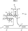
- the device 1 for controlling the charge of an aerosol according to the first embodiment of the invention has the advantage of not using additional air flow and therefore does not involve dilution during an aerosol / ionized air mixture.
- the charged species generated in the discharge zone 3 are entrained towards the post-discharge zone 5 by a flow of dry air AS.
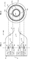
- the device 1000 comprises a discharge zone 63 with a dielectric barrier consisting of two concentric cylinders 632a and 632b made of dielectric material (alumina for example) and two main annular electrodes 631a and 631b.
- the two cylinders 632a and 632b and the two main annular electrodes 631a and 641b are also concentric.
- the external electrode 632a is in contact with the external wall of the external cylinder 632a while the internal electrode 631b is in contact with the internal wall of the internal cylinder 631b.
- the device 1000 according to the fourth embodiment further comprises a tubular body 68 which surrounds the discharge zone 63 and is connected to a conduit 641 which defines a mixing zone 64.
- the device (10000a, 10000b, 10000c) further comprises a body 78 which surrounds the discharge zone 73 and is connected on the one hand to the mouth of the dielectric tube 732a and on the other hand to a conduit 741 defining the zone 74 mixture.
- the post-discharge zone 75 is located between the conduit 741 and the discharge zone 73.
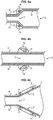
- the arrangement of the discharge zone 3 can be modified so as to increase the quantity of charged species extracted from the discharge zone 3 by electrostatic repulsion.
- the two dielectric surfaces 32 form a conduit 35 having a narrowing, the conduit 35 being wider on the side of the post-discharge zone 5 than on the side opposite to the post-discharge zone 5.
- the main metal electrodes 31 are positioned at the level of this narrowing. The result of the electrostatic repulsion forces which are exerted between the charged species formed in the discharge zone 3 is thus directed towards the post-discharge zone 5, increasing the quantity of charged species extracted from the zone 3 of discharge by electrostatic repulsion.
- the main metal electrodes31 have a shape such that they are narrower on the side opposite to the post-discharge zone 5 than on the side of the post-discharge zone 5.
- the result of the electrostatic repulsion forces exerted between the ions formed in the discharge zone 3 is directed towards the post-discharge zone 5, increasing the amount of charged species extracted from the discharge zone 3 by electrostatic repulsion.
Landscapes
- Physical Or Chemical Processes And Apparatus (AREA)
Claims (15)
- Vorrichtung (1, 10, 100, 1000, 10000) zur Steuerung der Ladung eines Aerosols, Folgendes beinhaltend:- einen Eingangsbereich (2, 62, 72a, 72b) für ein Aerosol (A);- einen Entladungsbereich (3, 63, 73), in welchem man geladene Arten erzeugt, wobei der Entladungsbereich (3, 63, 73) und der Eingangsbereich (2, 62, 72a, 72b) für das Aerosol (A) in Bezug aufeinander so angeordnet sind, dass das solchermaßen eingeleitete Aerosol (A) nicht durch den Entladungsbereich (3, 63, 73) zirkuliert;- einen Mischungsbereich (4, 64, 74) des Aerosols (A) mit einem Teil der geladenen Arten, welche aus dem Entladungsbereich (3, 63, 73) stammen;- einen Nachentladungsbereich (5, 65, 75) in Verbindung mit dem Entladungsbereich (3, 63, 73), wobei der Eingangsbereich (2, 62, 72a, 72b) für das Aerosol (A) und der Mischungsbereich (4, 64, 74) so angeordnet sind, dass mindestens ein Teil eines in dem Nachentladungsbereich (5, 65, 75) zirkulierenden Stroms mindestens einen Teil der in dem Entladungsbereich (3, 63, 73) gebildeten geladenen Arten (4, 64, 74) in Richtung des Mischungsbereichs (4, 64, 74) mitführt, dadurch gekennzeichnet, dass der Entladungsbereich ein Entladungsbereich mit dielektrischen Barrieren ist, wobei der Entladungsbereich so angeordnet ist, dass die Menge an geladenen Arten, welche aus dem Entladungsbereich extrahiert wird, in Richtung des Nachentladungsbereichs durch elektrostatische Abstoßung erhöht wird.
- Vorrichtung (1) zur Steuerung der Ladung eines Aerosols nach Anspruch 1, dadurch gekennzeichnet, dass der in dem Nachentladungsbereich (5) zirkulierende Strom das Aerosol (A) ist.
- Vorrichtung (10) zur Steuerung der Ladung eines Aerosols nach Anspruch 1, beinhaltend einen Eingangsbereich (26) für trockene Luft (AS) in Verbindung mit dem Entladungsbereich (3) in einer Weise, dass die trockene Luft (AS) in dem Entladungsbereich (3) zirkuliert.
- Vorrichtung (100) zur Steuerung der Ladung eines Aerosols nach Anspruch 1, beinhaltend einen Eingangsbereich (36) für trockene Luft (AS) in Verbindung mit dem Nachentladungsbereich (5) in einer Weise, dass die aus dem Entladungsbereich (5) stammenden geladenen Arten in Richtung des Nachentladungsbereichs (5) mitgeführt werden.
- Vorrichtung (1, 10, 100) zur Steuerung der Ladung eines Aerosols nach einem der vorhergehenden Ansprüche, bei welchem der Entladungsbereich (3) zwei Platten aus dielektrischem Material (32), welche einander gegenüber angeordnet sind und eine Leitung (35) bilden und zwei Hauptelektroden (31) beinhaltet, welche jeweils mit einer dielektrischen Platte (32) verbunden sind, wobei die Hauptelektroden geeignet sind, geladene Arten in dem Entladungsbereich (3) zu erzeugen.
- Vorrichtung (1000) zur Steuerung der Ladung eines Aerosols nach Anspruch 1, dadurch gekennzeichnet, dass der Entladungsbereich (63) mit dielektrischer Barriere zwei Zylinder (632a) und (632b) aus dielektrischem Material beinhaltet, welche zwischen einander eine Leitung (635) definieren, und zwei ringförmige, konzentrische Hauptelektroden (631a, 631b), wobei eine äußere Elektrode (632a) genannte Elektrode in Kontakt mit der äußeren Wand des äußeren Zylinders (632a) steht und eine innere Elektrode (631b) genannte Elektrode in Kontakt mit der inneren Wand des inneren Zylinders (631b) steht, wobei die Hauptelektroden (631a, 631b) geeignet sind, geladene Arten in dem Entladungsbereich (63) zu erzeugen.
- Vorrichtung (10000) zur Steuerung der Ladung eines Aerosols nach Anspruch 1, dadurch gekennzeichnet, dass der Entladungsbereich (73) mit dielektrischer Barriere eine Röhre aus dielektrischem Material (732a) beinhaltet, welche mit einem aufgeweiteten Mundstück und mit einer Platte aus dielektrischem Material (732b) versehen ist, welche gegenüber dem Mundstück der dielektrischen Röhre (732a) positioniert ist, wobei die Röhre aus dielektrischem Material (732a) und die Platte aus dielektrischem Material (732b) zwischen einander eine Leitung (735) definieren, mit einer ersten ringförmigen Elektrode (731a), welche in Kontakt mit der äußeren Wand der dielektrischen Röhre (732a) auf Höhe der Aufweitung der dielektrischen Röhre (732a) steht und mit einer zweiten ringförmigen Elektrode (731b) mit einem Durchmesser, welcher im Wesentlichen gleich dem Durchmesser der ersten Elektrode (731a) ist und in Kontakt mit der Seite der dielektrischen Platte (732b) steht, welche der dielektrischen Röhre (732a) gegenüber liegt, wobei die Hauptelektroden geeignet sind, geladene Arten in dem Entladungsbereich (73) zu erzeugen.
- Vorrichtung (1, 10, 100) zur Steuerung der Ladung eines Aerosols nach einem der Ansprüche 5 bis 7, dadurch gekennzeichnet, dass die Leitung (35, 635, 735) eine Verengung aufweist, wobei die metallischen Hauptelektroden (31, 631, 731) auf Höhe der Verengung positioniert sind, damit die Resultierende der elektrostatischen Abstoßungskräfte, welche zwischen den geladenen Arten wirken, welche in dem Entladungsbereich (3, 63, 73) gebildet werden, in Richtung des Nachentladungsbereichs (5, 65, 75) gelenkt wird.
- Vorrichtung (1, 10, 100) zur Steuerung der Ladung eines Aerosols nach einem der Ansprüche 5 bis 7, dadurch gekennzeichnet, dass die metallischen Hauptelektroden (31, 631, 731) eine solche Form aufweisen, dass sie schmaler an der dem Entladungsbereich (5, 65, 75) gegenüberliegenden Seite als an der Seite des Nachentladungsbereichs (5, 65, 75) in einer Weise sind, dass die Resultierende der elektrostatischen Abstoßungskräfte, welche zwischen den geladenen Arten wirken, welche in dem Entladungsbereich (3, 63, 73) gebildet werden, in Richtung des Nachentladungsbereichs (5, 65, 75) gelenkt wird.
- Vorrichtung (1, 10, 100) zur Steuerung der Ladung eines Aerosols nach einem der Ansprüche 5 bis 7, dadurch gekennzeichnet, dass die Leitung (35, 635, 735) eine Verengung aufweist, wobei der Entladungsbereich (3, 63, 73) zudem zwei metallische sekundäre Elektroden (31') beinhaltet, welche mit den metallischen Hauptelektroden (31, 631, 731) einen Entladungsbereich (3') mit sekundärer dielektrischer Barriere an der Oberfläche der Leitung (35, 635, 735) bildet.
- Vorrichtung (1, 10, 100, 1000, 10000) zur Steuerung der Ladung eines Aerosols nach einem der Ansprüche 5 bis 10, beinhaltend einen Hoch-Wechselspannungsgenerator, welcher mit den Hauptelektroden (31, 631a, 631b, 731a, 731b) in einer Weise verbunden ist, dass die Bildung von geladenen positiven und negativen Arten in dem Entladungsbereich (3, 63, 73) hervorgerufen wird.
- Vorrichtung (1, 10, 100, 1000, 10000) zur Steuerung der Ladung eines Aerosols nach einem der vorhergehenden Ansprüche, dadurch gekennzeichnet, dass der Nachentladungsbereich (5, 65, 75) zudem eine Nachentladungselektrode (7) beinhaltet, welche zur Steuerung der Ladung geeignet ist.
- Vorrichtung (1, 10, 100, 1000, 10000) zur Steuerung der Ladung eines Aerosols nach einem der Ansprüche 5 bis 12, dadurch gekennzeichnet, dass die Kontakte (34, 634, 734) zwischen den metallischen Hauptelektroden (31, 631a, 631b, 731a, 731b) und den dielektrischen Platten (32, 632a, 632b, 732a, 732b) mit einem Isoliermaterial bedeckt sind.
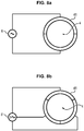
- Vorrichtung (1, 10, 100, 1000, 10000) zur Steuerung der Ladung eines Aerosols nach einem der Ansprüche 5 bis 13, dadurch gekennzeichnet, dass der Mischungsbereich (4, 64, 74) durch eine Leitung (41, 641, 741) definiert wird, wobei die Leitung (41, 641, 741) aus zwei halbzylindrischen Elektroden gebildet wird, welche durch einen Wechselstromgenerator (8) in einer Weise gespeist werden, dass ein Schwingungsfeld in dem Mischungsbereich (4, 64, 74) gebildet wird.
- Vorrichtung (1, 10, 100, 1000, 10000) zur Steuerung der Ladung eines Aerosols nach einem der Ansprüche 5 bis 13, dadurch gekennzeichnet, dass der Mischungsbereich (4, 64, 74) durch eine Leitung (41, 641, 741) definiert wird, wobei die Leitung (41, 641, 741) aus drei Elektroden gebildet wird, welche durch einen Drehstromgenerator (8') in einer Weise gespeist werden, dass ein Drehfeld in dem Mischungsbereich (4, 64, 74) gebildet wird.
Applications Claiming Priority (2)
| Application Number | Priority Date | Filing Date | Title |
|---|---|---|---|
| FR1262849A FR3000413B1 (fr) | 2012-12-27 | 2012-12-27 | Dispositif pour controler la charge d'un aerosol en post-decharge |
| PCT/EP2013/077947 WO2014102257A1 (fr) | 2012-12-27 | 2013-12-23 | Dispositif pour controler la charge d'un aerosol en post-decharge |
Publications (2)
| Publication Number | Publication Date |
|---|---|
| EP2938437A1 EP2938437A1 (de) | 2015-11-04 |
| EP2938437B1 true EP2938437B1 (de) | 2020-05-27 |
Family
ID=48613679
Family Applications (1)
| Application Number | Title | Priority Date | Filing Date |
|---|---|---|---|
| EP13821485.3A Active EP2938437B1 (de) | 2012-12-27 | 2013-12-23 | Vorrichtung zur steuerung der ladung nach einer aerosolsentladung |
Country Status (4)
| Country | Link |
|---|---|
| US (1) | US10173226B2 (de) |
| EP (1) | EP2938437B1 (de) |
| FR (1) | FR3000413B1 (de) |
| WO (1) | WO2014102257A1 (de) |
Families Citing this family (2)
| Publication number | Priority date | Publication date | Assignee | Title |
|---|---|---|---|---|
| US10616954B2 (en) | 2014-04-17 | 2020-04-07 | S. C. Johnson & Son, Inc. | Electrical barrier for wax warmer |
| US9655168B2 (en) | 2014-04-17 | 2017-05-16 | S.C. Johnson & Son, Inc. | Electrical barrier for wax warmer |
Family Cites Families (7)
| Publication number | Priority date | Publication date | Assignee | Title |
|---|---|---|---|---|
| US4339782A (en) * | 1980-03-27 | 1982-07-13 | The Bahnson Company | Supersonic jet ionizer |
| SE447797B (sv) * | 1980-05-29 | 1986-12-15 | Onera (Off Nat Aerospatiale) | Sett och anordning for separering av svevande partiklar fran en gas |
| US6635106B2 (en) * | 2000-03-03 | 2003-10-21 | Matsushita Seiko Co., Ltd. | Dust collecting apparatus and air-conditioning apparatus |
| EP1293216A4 (de) * | 2000-05-18 | 2003-08-20 | Sharp Kk | Verfahren zur sterilisation, ionenerzeugendes element, ionen erzeugende vorrichtung und klimaanlage |
| KR100535123B1 (ko) * | 2003-12-31 | 2005-12-07 | 현대자동차주식회사 | 하이브리드형 차량용 공기 청정기 |
| US20130265689A1 (en) * | 2009-05-16 | 2013-10-10 | Gip Messinstrumente Gmbh | Method and device for neutralizing aerosol particles |
| US8416552B2 (en) * | 2009-10-23 | 2013-04-09 | Illinois Tool Works Inc. | Self-balancing ionized gas streams |
-
2012
- 2012-12-27 FR FR1262849A patent/FR3000413B1/fr not_active Expired - Fee Related
-
2013
- 2013-12-23 EP EP13821485.3A patent/EP2938437B1/de active Active
- 2013-12-23 WO PCT/EP2013/077947 patent/WO2014102257A1/fr not_active Ceased
- 2013-12-23 US US14/655,550 patent/US10173226B2/en not_active Expired - Fee Related
Non-Patent Citations (1)
| Title |
|---|
| None * |
Also Published As
| Publication number | Publication date |
|---|---|
| FR3000413B1 (fr) | 2016-01-08 |
| EP2938437A1 (de) | 2015-11-04 |
| WO2014102257A1 (fr) | 2014-07-03 |
| US20150352563A1 (en) | 2015-12-10 |
| US10173226B2 (en) | 2019-01-08 |
| FR3000413A1 (fr) | 2014-07-04 |
Similar Documents
| Publication | Publication Date | Title |
|---|---|---|
| EP0051006B1 (de) | Verfahren und Vorrichtungen zum Übertragen elektrischer Ladungen verschiedener Zeichen in ein Raumgebiet und Verwendung in Vorrichtungen zum Beseitigen statischer Elektrizität | |
| EP1064100B9 (de) | Mittel zur elektrohyrodynamischen zerstäubung | |
| EP3328548B1 (de) | Verfahren und vorrichtung zum selektiven sammeln von aerosolpartikeln nach partikelgrösse | |
| EP2939317B1 (de) | Konzentrischer funkenerosiver aerosollader | |
| EP3160651B1 (de) | Elektrostatischer kollektor | |
| EP2656921B1 (de) | Elektrostatische Sammelvorrichtung von Suspensionspartikeln in einem gasförmigen Milieu | |
| WO2011001070A1 (fr) | Dispositif d'émission d'un jet de plasma à partir de l'air atmosphérique à température et pression ambiantes et utilisation d'un tel dispositif | |
| WO2006070082A1 (fr) | Eclateur multicanal a intervalles multiples et generateur de haute puissance pulsee | |
| WO2014102257A1 (fr) | Dispositif pour controler la charge d'un aerosol en post-decharge | |
| Seto et al. | Formation of highly charged nanodroplets by condensation–electrospray device | |
| WO2008091519A1 (en) | Device for remediation of gaseous and aerosol streams | |
| EP2038521B1 (de) | Vorrichtung und verfahren zum auffangen und beseitigen von in abgasen aus einem kraftfahrzeug-verbrennungsmotor enthaltenen partikeln | |
| US20110265653A1 (en) | Device for collecting particles that have a strong electron affinity | |
| Deputatova et al. | Confinement of charged microparticles in a gas flow by the linear Paul trap | |
| CH642870A5 (fr) | Procede et dispositif de separation de particules en suspension dans un gaz. | |
| EP0861576B1 (de) | Plasmalichtbogenstrom-erzeugungsvorrichtung mit geschlossener konfiguration | |
| WO2018115774A1 (fr) | Réacteur plasma de décharge à barrière diélectrique | |
| EP0437383A1 (de) | Verfahren und Vorrichtung zum elektrostatischen Spritzlackieren von Kunststoffgegenständen | |
| Patarashvili et al. | Development and research of charger operation modes type “needle-plate” for nanoparticle charging | |
| Opaits et al. | Suppression of Dielectric Barrier Discharge Charge Build up Using a Partially Conducting Thin Film | |
| Podliński et al. | Measurements of EHD flow patterns in ESP with DC+ Pulsed voltage hybrid power supply | |
| Devos et al. | Nanosecond plasma discharge dynamics on a levitated water droplet | |
| Bouarouri et al. | Corona discharge used as an ion source for aerosol charging | |
| Tancogne-Dejean | Study and characteristics of a VIVITRON type electrostatic accelerator | |
| Nicolas | Development of a high-power 500kV pulse line |
Legal Events
| Date | Code | Title | Description |
|---|---|---|---|
| PUAI | Public reference made under article 153(3) epc to a published international application that has entered the european phase |
Free format text: ORIGINAL CODE: 0009012 |
|
| 17P | Request for examination filed |
Effective date: 20150709 |
|
| AK | Designated contracting states |
Kind code of ref document: A1 Designated state(s): AL AT BE BG CH CY CZ DE DK EE ES FI FR GB GR HR HU IE IS IT LI LT LU LV MC MK MT NL NO PL PT RO RS SE SI SK SM TR |
|
| AX | Request for extension of the european patent |
Extension state: BA ME |
|
| DAX | Request for extension of the european patent (deleted) | ||
| STAA | Information on the status of an ep patent application or granted ep patent |
Free format text: STATUS: EXAMINATION IS IN PROGRESS |
|
| 17Q | First examination report despatched |
Effective date: 20181001 |
|
| GRAP | Despatch of communication of intention to grant a patent |
Free format text: ORIGINAL CODE: EPIDOSNIGR1 |
|
| STAA | Information on the status of an ep patent application or granted ep patent |
Free format text: STATUS: GRANT OF PATENT IS INTENDED |
|
| INTG | Intention to grant announced |
Effective date: 20191217 |
|
| GRAS | Grant fee paid |
Free format text: ORIGINAL CODE: EPIDOSNIGR3 |
|
| GRAA | (expected) grant |
Free format text: ORIGINAL CODE: 0009210 |
|
| STAA | Information on the status of an ep patent application or granted ep patent |
Free format text: STATUS: THE PATENT HAS BEEN GRANTED |
|
| AK | Designated contracting states |
Kind code of ref document: B1 Designated state(s): AL AT BE BG CH CY CZ DE DK EE ES FI FR GB GR HR HU IE IS IT LI LT LU LV MC MK MT NL NO PL PT RO RS SE SI SK SM TR |
|
| REG | Reference to a national code |
Ref country code: GB Ref legal event code: FG4D Free format text: NOT ENGLISH |
|
| REG | Reference to a national code |
Ref country code: CH Ref legal event code: EP |
|
| REG | Reference to a national code |
Ref country code: AT Ref legal event code: REF Ref document number: 1273993 Country of ref document: AT Kind code of ref document: T Effective date: 20200615 |
|
| REG | Reference to a national code |
Ref country code: DE Ref legal event code: R096 Ref document number: 602013069462 Country of ref document: DE |
|
| REG | Reference to a national code |
Ref country code: LT Ref legal event code: MG4D |
|
| PG25 | Lapsed in a contracting state [announced via postgrant information from national office to epo] |
Ref country code: LT Free format text: LAPSE BECAUSE OF FAILURE TO SUBMIT A TRANSLATION OF THE DESCRIPTION OR TO PAY THE FEE WITHIN THE PRESCRIBED TIME-LIMIT Effective date: 20200527 Ref country code: NO Free format text: LAPSE BECAUSE OF FAILURE TO SUBMIT A TRANSLATION OF THE DESCRIPTION OR TO PAY THE FEE WITHIN THE PRESCRIBED TIME-LIMIT Effective date: 20200827 Ref country code: IS Free format text: LAPSE BECAUSE OF FAILURE TO SUBMIT A TRANSLATION OF THE DESCRIPTION OR TO PAY THE FEE WITHIN THE PRESCRIBED TIME-LIMIT Effective date: 20200927 Ref country code: GR Free format text: LAPSE BECAUSE OF FAILURE TO SUBMIT A TRANSLATION OF THE DESCRIPTION OR TO PAY THE FEE WITHIN THE PRESCRIBED TIME-LIMIT Effective date: 20200828 Ref country code: FI Free format text: LAPSE BECAUSE OF FAILURE TO SUBMIT A TRANSLATION OF THE DESCRIPTION OR TO PAY THE FEE WITHIN THE PRESCRIBED TIME-LIMIT Effective date: 20200527 Ref country code: PT Free format text: LAPSE BECAUSE OF FAILURE TO SUBMIT A TRANSLATION OF THE DESCRIPTION OR TO PAY THE FEE WITHIN THE PRESCRIBED TIME-LIMIT Effective date: 20200928 Ref country code: SE Free format text: LAPSE BECAUSE OF FAILURE TO SUBMIT A TRANSLATION OF THE DESCRIPTION OR TO PAY THE FEE WITHIN THE PRESCRIBED TIME-LIMIT Effective date: 20200527 |
|
| REG | Reference to a national code |
Ref country code: NL Ref legal event code: MP Effective date: 20200527 |
|
| PG25 | Lapsed in a contracting state [announced via postgrant information from national office to epo] |
Ref country code: HR Free format text: LAPSE BECAUSE OF FAILURE TO SUBMIT A TRANSLATION OF THE DESCRIPTION OR TO PAY THE FEE WITHIN THE PRESCRIBED TIME-LIMIT Effective date: 20200527 Ref country code: BG Free format text: LAPSE BECAUSE OF FAILURE TO SUBMIT A TRANSLATION OF THE DESCRIPTION OR TO PAY THE FEE WITHIN THE PRESCRIBED TIME-LIMIT Effective date: 20200827 Ref country code: RS Free format text: LAPSE BECAUSE OF FAILURE TO SUBMIT A TRANSLATION OF THE DESCRIPTION OR TO PAY THE FEE WITHIN THE PRESCRIBED TIME-LIMIT Effective date: 20200527 Ref country code: LV Free format text: LAPSE BECAUSE OF FAILURE TO SUBMIT A TRANSLATION OF THE DESCRIPTION OR TO PAY THE FEE WITHIN THE PRESCRIBED TIME-LIMIT Effective date: 20200527 |
|
| REG | Reference to a national code |
Ref country code: AT Ref legal event code: MK05 Ref document number: 1273993 Country of ref document: AT Kind code of ref document: T Effective date: 20200527 |
|
| PG25 | Lapsed in a contracting state [announced via postgrant information from national office to epo] |
Ref country code: AL Free format text: LAPSE BECAUSE OF FAILURE TO SUBMIT A TRANSLATION OF THE DESCRIPTION OR TO PAY THE FEE WITHIN THE PRESCRIBED TIME-LIMIT Effective date: 20200527 Ref country code: NL Free format text: LAPSE BECAUSE OF FAILURE TO SUBMIT A TRANSLATION OF THE DESCRIPTION OR TO PAY THE FEE WITHIN THE PRESCRIBED TIME-LIMIT Effective date: 20200527 |
|
| PG25 | Lapsed in a contracting state [announced via postgrant information from national office to epo] |
Ref country code: ES Free format text: LAPSE BECAUSE OF FAILURE TO SUBMIT A TRANSLATION OF THE DESCRIPTION OR TO PAY THE FEE WITHIN THE PRESCRIBED TIME-LIMIT Effective date: 20200527 Ref country code: IT Free format text: LAPSE BECAUSE OF FAILURE TO SUBMIT A TRANSLATION OF THE DESCRIPTION OR TO PAY THE FEE WITHIN THE PRESCRIBED TIME-LIMIT Effective date: 20200527 Ref country code: SM Free format text: LAPSE BECAUSE OF FAILURE TO SUBMIT A TRANSLATION OF THE DESCRIPTION OR TO PAY THE FEE WITHIN THE PRESCRIBED TIME-LIMIT Effective date: 20200527 Ref country code: AT Free format text: LAPSE BECAUSE OF FAILURE TO SUBMIT A TRANSLATION OF THE DESCRIPTION OR TO PAY THE FEE WITHIN THE PRESCRIBED TIME-LIMIT Effective date: 20200527 Ref country code: DK Free format text: LAPSE BECAUSE OF FAILURE TO SUBMIT A TRANSLATION OF THE DESCRIPTION OR TO PAY THE FEE WITHIN THE PRESCRIBED TIME-LIMIT Effective date: 20200527 Ref country code: EE Free format text: LAPSE BECAUSE OF FAILURE TO SUBMIT A TRANSLATION OF THE DESCRIPTION OR TO PAY THE FEE WITHIN THE PRESCRIBED TIME-LIMIT Effective date: 20200527 Ref country code: RO Free format text: LAPSE BECAUSE OF FAILURE TO SUBMIT A TRANSLATION OF THE DESCRIPTION OR TO PAY THE FEE WITHIN THE PRESCRIBED TIME-LIMIT Effective date: 20200527 Ref country code: CZ Free format text: LAPSE BECAUSE OF FAILURE TO SUBMIT A TRANSLATION OF THE DESCRIPTION OR TO PAY THE FEE WITHIN THE PRESCRIBED TIME-LIMIT Effective date: 20200527 |
|
| PG25 | Lapsed in a contracting state [announced via postgrant information from national office to epo] |
Ref country code: PL Free format text: LAPSE BECAUSE OF FAILURE TO SUBMIT A TRANSLATION OF THE DESCRIPTION OR TO PAY THE FEE WITHIN THE PRESCRIBED TIME-LIMIT Effective date: 20200527 Ref country code: SK Free format text: LAPSE BECAUSE OF FAILURE TO SUBMIT A TRANSLATION OF THE DESCRIPTION OR TO PAY THE FEE WITHIN THE PRESCRIBED TIME-LIMIT Effective date: 20200527 |
|
| REG | Reference to a national code |
Ref country code: DE Ref legal event code: R097 Ref document number: 602013069462 Country of ref document: DE |
|
| PLBE | No opposition filed within time limit |
Free format text: ORIGINAL CODE: 0009261 |
|
| STAA | Information on the status of an ep patent application or granted ep patent |
Free format text: STATUS: NO OPPOSITION FILED WITHIN TIME LIMIT |
|
| 26N | No opposition filed |
Effective date: 20210302 |
|
| PG25 | Lapsed in a contracting state [announced via postgrant information from national office to epo] |
Ref country code: SI Free format text: LAPSE BECAUSE OF FAILURE TO SUBMIT A TRANSLATION OF THE DESCRIPTION OR TO PAY THE FEE WITHIN THE PRESCRIBED TIME-LIMIT Effective date: 20200527 |
|
| REG | Reference to a national code |
Ref country code: CH Ref legal event code: PL |
|
| PG25 | Lapsed in a contracting state [announced via postgrant information from national office to epo] |
Ref country code: MC Free format text: LAPSE BECAUSE OF FAILURE TO SUBMIT A TRANSLATION OF THE DESCRIPTION OR TO PAY THE FEE WITHIN THE PRESCRIBED TIME-LIMIT Effective date: 20200527 |
|
| REG | Reference to a national code |
Ref country code: BE Ref legal event code: MM Effective date: 20201231 |
|
| PG25 | Lapsed in a contracting state [announced via postgrant information from national office to epo] |
Ref country code: LU Free format text: LAPSE BECAUSE OF NON-PAYMENT OF DUE FEES Effective date: 20201223 Ref country code: IE Free format text: LAPSE BECAUSE OF NON-PAYMENT OF DUE FEES Effective date: 20201223 |
|
| PG25 | Lapsed in a contracting state [announced via postgrant information from national office to epo] |
Ref country code: CH Free format text: LAPSE BECAUSE OF NON-PAYMENT OF DUE FEES Effective date: 20201231 Ref country code: LI Free format text: LAPSE BECAUSE OF NON-PAYMENT OF DUE FEES Effective date: 20201231 |
|
| PGFP | Annual fee paid to national office [announced via postgrant information from national office to epo] |
Ref country code: GB Payment date: 20211220 Year of fee payment: 9 Ref country code: FR Payment date: 20211231 Year of fee payment: 9 Ref country code: DE Payment date: 20211210 Year of fee payment: 9 |
|
| PG25 | Lapsed in a contracting state [announced via postgrant information from national office to epo] |
Ref country code: TR Free format text: LAPSE BECAUSE OF FAILURE TO SUBMIT A TRANSLATION OF THE DESCRIPTION OR TO PAY THE FEE WITHIN THE PRESCRIBED TIME-LIMIT Effective date: 20200527 Ref country code: MT Free format text: LAPSE BECAUSE OF FAILURE TO SUBMIT A TRANSLATION OF THE DESCRIPTION OR TO PAY THE FEE WITHIN THE PRESCRIBED TIME-LIMIT Effective date: 20200527 Ref country code: CY Free format text: LAPSE BECAUSE OF FAILURE TO SUBMIT A TRANSLATION OF THE DESCRIPTION OR TO PAY THE FEE WITHIN THE PRESCRIBED TIME-LIMIT Effective date: 20200527 |
|
| PG25 | Lapsed in a contracting state [announced via postgrant information from national office to epo] |
Ref country code: MK Free format text: LAPSE BECAUSE OF FAILURE TO SUBMIT A TRANSLATION OF THE DESCRIPTION OR TO PAY THE FEE WITHIN THE PRESCRIBED TIME-LIMIT Effective date: 20200527 |
|
| PG25 | Lapsed in a contracting state [announced via postgrant information from national office to epo] |
Ref country code: BE Free format text: LAPSE BECAUSE OF NON-PAYMENT OF DUE FEES Effective date: 20201231 |
|
| REG | Reference to a national code |
Ref country code: DE Ref legal event code: R119 Ref document number: 602013069462 Country of ref document: DE |
|
| GBPC | Gb: european patent ceased through non-payment of renewal fee |
Effective date: 20221223 |
|
| PG25 | Lapsed in a contracting state [announced via postgrant information from national office to epo] |
Ref country code: GB Free format text: LAPSE BECAUSE OF NON-PAYMENT OF DUE FEES Effective date: 20221223 Ref country code: DE Free format text: LAPSE BECAUSE OF NON-PAYMENT OF DUE FEES Effective date: 20230701 |
|
| PG25 | Lapsed in a contracting state [announced via postgrant information from national office to epo] |
Ref country code: FR Free format text: LAPSE BECAUSE OF NON-PAYMENT OF DUE FEES Effective date: 20221231 |