EP2938442B1 - Generateur de vibrations pour dispositifs de compactage du sol dirigeables - Google Patents
Generateur de vibrations pour dispositifs de compactage du sol dirigeables Download PDFInfo
- Publication number
- EP2938442B1 EP2938442B1 EP13798247.6A EP13798247A EP2938442B1 EP 2938442 B1 EP2938442 B1 EP 2938442B1 EP 13798247 A EP13798247 A EP 13798247A EP 2938442 B1 EP2938442 B1 EP 2938442B1
- Authority
- EP
- European Patent Office
- Prior art keywords
- imbalance
- imbalance shaft
- shaft half
- shaft
- vibration exciter
- Prior art date
- Legal status (The legal status is an assumption and is not a legal conclusion. Google has not performed a legal analysis and makes no representation as to the accuracy of the status listed.)
- Active
Links
Images
Classifications
-
- B—PERFORMING OPERATIONS; TRANSPORTING
- B06—GENERATING OR TRANSMITTING MECHANICAL VIBRATIONS IN GENERAL
- B06B—METHODS OR APPARATUS FOR GENERATING OR TRANSMITTING MECHANICAL VIBRATIONS OF INFRASONIC, SONIC, OR ULTRASONIC FREQUENCY, e.g. FOR PERFORMING MECHANICAL WORK IN GENERAL
- B06B1/00—Methods or apparatus for generating mechanical vibrations of infrasonic, sonic, or ultrasonic frequency
- B06B1/10—Methods or apparatus for generating mechanical vibrations of infrasonic, sonic, or ultrasonic frequency making use of mechanical energy
- B06B1/16—Methods or apparatus for generating mechanical vibrations of infrasonic, sonic, or ultrasonic frequency making use of mechanical energy operating with systems involving rotary unbalanced masses
- B06B1/161—Adjustable systems, i.e. where amplitude or direction of frequency of vibration can be varied
- B06B1/166—Where the phase-angle of masses mounted on counter-rotating shafts can be varied, e.g. variation of the vibration phase
-
- E—FIXED CONSTRUCTIONS
- E01—CONSTRUCTION OF ROADS, RAILWAYS, OR BRIDGES
- E01C—CONSTRUCTION OF, OR SURFACES FOR, ROADS, SPORTS GROUNDS, OR THE LIKE; MACHINES OR AUXILIARY TOOLS FOR CONSTRUCTION OR REPAIR
- E01C19/00—Machines, tools or auxiliary devices for preparing or distributing paving materials, for working the placed materials, or for forming, consolidating, or finishing the paving
- E01C19/22—Machines, tools or auxiliary devices for preparing or distributing paving materials, for working the placed materials, or for forming, consolidating, or finishing the paving for consolidating or finishing laid-down unset materials
- E01C19/30—Tamping or vibrating apparatus other than rollers ; Devices for ramming individual paving elements
- E01C19/34—Power-driven rammers or tampers, e.g. air-hammer impacted shoes for ramming stone-sett paving; Hand-actuated ramming or tamping machines, e.g. tampers with manually hoisted dropping weight
- E01C19/38—Power-driven rammers or tampers, e.g. air-hammer impacted shoes for ramming stone-sett paving; Hand-actuated ramming or tamping machines, e.g. tampers with manually hoisted dropping weight with means specifically for generating vibrations, e.g. vibrating plate compactors, immersion vibrators
-
- E—FIXED CONSTRUCTIONS
- E02—HYDRAULIC ENGINEERING; FOUNDATIONS; SOIL SHIFTING
- E02D—FOUNDATIONS; EXCAVATIONS; EMBANKMENTS; UNDERGROUND OR UNDERWATER STRUCTURES
- E02D3/00—Improving or preserving soil or rock, e.g. preserving permafrost soil
- E02D3/02—Improving by compacting
- E02D3/046—Improving by compacting by tamping or vibrating, e.g. with auxiliary watering of the soil
-
- E—FIXED CONSTRUCTIONS
- E02—HYDRAULIC ENGINEERING; FOUNDATIONS; SOIL SHIFTING
- E02D—FOUNDATIONS; EXCAVATIONS; EMBANKMENTS; UNDERGROUND OR UNDERWATER STRUCTURES
- E02D3/00—Improving or preserving soil or rock, e.g. preserving permafrost soil
- E02D3/02—Improving by compacting
- E02D3/046—Improving by compacting by tamping or vibrating, e.g. with auxiliary watering of the soil
- E02D3/074—Vibrating apparatus operating with systems involving rotary unbalanced masses
-
- Y—GENERAL TAGGING OF NEW TECHNOLOGICAL DEVELOPMENTS; GENERAL TAGGING OF CROSS-SECTIONAL TECHNOLOGIES SPANNING OVER SEVERAL SECTIONS OF THE IPC; TECHNICAL SUBJECTS COVERED BY FORMER USPC CROSS-REFERENCE ART COLLECTIONS [XRACs] AND DIGESTS
- Y10—TECHNICAL SUBJECTS COVERED BY FORMER USPC
- Y10T—TECHNICAL SUBJECTS COVERED BY FORMER US CLASSIFICATION
- Y10T74/00—Machine element or mechanism
- Y10T74/18—Mechanical movements
- Y10T74/18056—Rotary to or from reciprocating or oscillating
- Y10T74/18344—Unbalanced weights
Definitions
- the invention relates to a vibration exciter for a soil compacting device.
- Steerable soil compactors or vibratory plates for use in the construction industry have long been known. For example, show the G 78 18 542.9 and the DE 101 05 687 A1 steerable soil compaction devices in which a vibration exciter is arranged in a housing on a ground contact plate.
- the vibration exciters shown have two mutually oppositely rotatably coupled unbalanced shafts with unbalanced masses formed thereon, whose phase angle is adjustable relative to each other. By adjusting the phase position, the direction of action of a resultant force vector generated by the rotating imbalance masses can be changed such that the soil compaction device moves in the forward and backward direction.
- two unbalanced masses which are rotatable relative to the imbalance shaft are arranged axially offset relative to one another on one of the imbalance shafts.
- the position of each of the two imbalance masses with respect to the imbalance shaft carrying it is individually adjustable, so that in conjunction with the opposite, further imbalance wave resulting force vectors can be achieved, which generate a yaw moment about a vertical axis of the soil compacting device.
- a rotation of the soil compacting device and thus a steering are possible without further forces from the outside, for example by an operator, must act on the soil compacting device.
- a vibration exciter for a soil compacting device is known, with two mutually axially parallel unbalanced shafts, wherein one of the unbalanced shafts is divided into two mutually coaxial arranged unbalanced shafts halves.
- Each of the two imbalance shaft halves carries an imbalance mass which is rotatable in opposite directions to a corresponding imbalance mass on the other unbalanced shaft.
- the invention has for its object to provide a vibration exciter, which achieves a high rotational dynamics in a robust design and thus improves the handling of the soil compacting device.
- a vibration exciter for a soil compacting device has a first imbalance shaft, one arranged parallel to the axis of the first imbalance shaft, with the second unbalanced shaft having a first unbalanced shaft half and a coaxial to the first unbalanced shaft half, rotatable relative to the first unbalanced shaft half second unbalanced shaft half, and wherein on the first Unbalanced shaft, arranged on the first unbalanced shaft half and on the second unbalanced shaft half in each case at least one imbalance mass or formed and / or fixed.
- the first imbalance shaft and the second imbalance shaft may be arranged within a housing, wherein the housing is coupled to a ground contact plate of the soil compaction device or vibrating plate.
- the drive device such as an electric or internal combustion engine, be arranged and be coupled to the driven imbalance shaft, for example by means of a shaft and / or a belt device.
- the electric or combustion engine can be located on the upper mass, for example, not directly on the housing (exciter housing).
- Power transmission may be belt or hydraulic.
- the drive device may be coupled to the first unbalanced imbalance shaft.
- the drive device can put the first and the second imbalance shaft and the imbalance masses formed thereon in an opposite rotational movement.
- a resulting Force vector of the forces acting on the imbalance centrifugal forces can be generated by a working movement of the ground contact plate.
- By rotating the imbalance masses arranged on the second imbalance shaft relative to the imbalance mass arranged on the first imbalance shaft its phase position is changed relative to the imbalance mass arranged on the first imbalance shaft in such a way that the resulting force vector causes a forward or backward movement as well as a shaking motion in the stationary state.
- each imbalance shaft half Since the two imbalance shaft halves are rotatable relative to each other, the respective imbalance masses can be formed directly on the respective imbalance shaft halves or attached thereto. Consequently, each unbalanced shaft half carries a mass attached to it. It is therefore not necessary to arrange the imbalance masses of the second imbalance shaft individually rotatable, for example by means of an adjustable sleeve. This allows a cost-effective and at the same time robust execution of the second imbalance shaft.
- the vibration generator has a coupling device for the positive, relatively rotatable coupling of the first unbalanced shaft half and the second unbalanced shaft half.
- the coupling device allows a positive coupling of the two unbalanced shaft halves and thus a common rotational behavior of the two unbalanced shaft halves as a second unbalanced shaft.
- the relative rotatability of the coupling makes it possible to rotate the imbalance masses formed on the two unbalanced shaft halves individually and relative to one another about the axis of rotation and thus to one another with mutually shifted phase position in rotation to offset what allows the generation of the yawing moment and thus the steering of the soil compacting device during operation.
- the vibration generator has a twisting device for rotating the first unbalanced shaft half relative to the second unbalanced shaft half and / or relative to the coupling device.
- the twisting device makes it possible to rotate the first unbalanced shaft half and the imbalance mass disposed thereon individually and relative to the second unbalanced shaft half or relative to the coupling device.
- the twisting can be carried out, for example, to an operator request at standstill and / or during the working operation of the soil compacting device. This allows the operator to control, for example, by operating an operating device of the soil compacting device or by operating an operating device on a remote control of the soil compacting device, the yawing moment and thus the direction of movement of the soil compaction device and thus to steer the soil compacting device.
- the twisting device for the first unbalanced shaft half can be arranged according to additionally a further rotating device for rotating the second unbalanced shaft half relative to the first unbalanced shaft half and / or relative to the coupling device on the vibration exciter.
- a further rotating device for rotating the second unbalanced shaft half relative to the first unbalanced shaft half and / or relative to the coupling device on the vibration exciter can be arranged according to additionally a further rotating device for rotating the second unbalanced shaft half relative to the first unbalanced shaft half and / or relative to the coupling device on the vibration exciter.
- mirror-symmetrical design of the vibration exciter or soil compaction device allows a balanced on both sides steering and handling.
- first imbalance shaft and the second imbalance shaft can be coupled to one another in a form-fitting manner and in opposite directions by the coupling device.
- the coupling device, the first imbalance shaft, the first imbalance shaft half and the second imbalance shaft half each form-fitting coupled.
- the coupling device thus coupled on the one hand, the first and second unbalanced shaft half, which form the second imbalance shaft by this coupling.
- the second imbalance shaft can also be positively coupled in opposite directions via the coupling device with the first imbalance shaft. Consequently, the coupling device positively couples the waves or shaft halves carrying the imbalance masses and thus ensures a uniform driving behavior in accordance with an operator request.
- the coupling device may comprise a sleeve device for receiving at least a portion of the first unbalanced shaft half and / or the second unbalanced shaft half.
- the sleeve device favors the positive coupling of the first and the second unbalanced shaft half with the coupling device, for example, by axially inserting the respective unbalanced shaft half in the sleeve device, so that the sleeve extends over a respective shaft end of the first and the second unbalanced shaft halves. Furthermore, it favors the coaxial arrangement with, for example, front side unbalanced shaft halves. In addition, for example, substantially cylindrical recesses of the sleeve device allow the relative rotation of the unbalanced shaft halves to the coupling device or each other.
- the sleeve device has on its outer side a gear wheel device for engagement in a further gear wheel device coupled to the first imbalance shaft.
- the coupling device may be formed, for example, as a sleeve for the two-sided form-fitting, but rotatable relative to the sleeve coupling the respective unbalanced shaft half with a mounted on the sleeve, rotating gear.
- the two gear devices can intervene, for example, directly meshing with each other and thus ensure the positive and counterrotatable coupling of the two unbalanced shafts.
- the rotating device has an engagement element arranged on the first unbalanced shaft half and displaceable axially relative to the first unbalanced shaft half for positive engagement in a recess of the first unbalanced shaft half and for positive engagement in a recess of the coupling device and / or the sleeve device. At least one of the recesses has an at least piecewise helical groove.
- the control slide is displaceable by an actuating device, for example a piston / cylinder unit and / or a mechanical or electromechanical actuating device.
- the further, arranged on the second unbalanced half shaft twisting device may have such a configuration and thereby the relative Ensure twistability of the second unbalanced shaft half to the coupling device.
- the engagement element in this embodiment produces the positive coupling between the first unbalanced shaft half and the coupling device. It may be displaceable by the control slide and thereby perform a movement with at least one axially guided along the axis of rotation of the first unbalanced half shaft movement component. On the one hand, it engages in a form-fitting manner in a recess of the first unbalanced shaft half, for example in a groove in the first unbalanced shaft half designed as a hollow shaft. On the other hand, the engagement element engages positively in a recess of the coupling device and / or the sleeve device, for example in a groove introduced into the sleeve device.
- the first unbalanced shaft half is rotated relative to the coupling device or sleeve device when the engagement element is displaced.
- the spool relative to the first unbalanced shaft half of the engagement member remains engaged with both the first unbalanced shaft half and with the sleeve means and thus establishes the positive coupling ago, which ensures the common rotation of unbalanced shaft half and coupling device.
- the first unbalanced shaft half has a cavity.
- the spool and the actuator and / or the piston / cylinder unit are disposed within the cavity.
- the second unbalanced shaft half can also have a cavity in which corresponding parts of the further rotation device can be arranged.
- the first (or second) unbalanced shaft half may be at least partially formed as a hollow shaft, in which the twisting device or parts of the rotating device such as the spool valve, the actuator and / or the piston / cylinder unit can be arranged. Parts of the twisting device such as the actuating device, the piston / cylinder unit and / or the spool can thereby be rotationally coupled by a rotation of the respective unbalanced shaft half, for example by a rotary decoupling device and thus rotatably arranged to the housing.
- the rotary decoupling device may include a bearing device such as a ball bearing.
- Such an arrangement of at least parts of the twisting device within the second imbalance shaft makes it possible to save installation space, in particular in a region laterally of the second imbalance shaft, and thereby make the soil compacting device narrow.
- an orbit of the unbalanced mass formed on the first unbalanced shaft half around the first unbalanced shaft half at least partially encloses the cavity, the actuating device, a piston of the piston / cylinder unit and / or a cylinder of the piston / cylinder unit.
- the imbalance mass formed on the first unbalanced shaft half outside of the first imbalance shaft half is possible to arrange the imbalance mass formed on the first unbalanced shaft half outside of the first imbalance shaft half, on a side of the first imbalance shaft half facing away from the coupling device, for example with the greatest possible distance to a center or symmetry plane of the soil compaction device perpendicular to the ground contact plate.
- a large lever arm of the centrifugal force vector generated by the rotation of the imbalance mass is achieved, whereby a particularly high rotational or yaw rate can be achieved about the vertical axis of the soil compacting device.
- the unbalanced mass formed on the first imbalance half can be arranged far outside the housing in such an embodiment, since no separate space must be provided laterally next to the second imbalance shaft to order the example taken completely in the respective unbalanced shafts halves twisting device. Consequently, the second unbalanced shaft can be made wide, which as described above leads to a large lever arm of the centrifugal force vectors and thus to a high rotation rate. Furthermore, the housing can be made compact and only slightly wider than the second unbalanced half shaft.
- a bearing device for supporting the first unbalanced shaft half is arranged axially in the housing between the unbalanced mass arranged on the first unbalanced shaft half and the coupling device and / or the sleeve device.
- the first unbalanced shaft half enclosing further storage device for supporting the first unbalanced shaft half arranged in the housing.
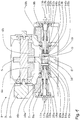
- the figure shows schematically an embodiment of a vibration exciter 1 in a top view with a section in a plane extending substantially parallel to the floor surface to be machined.
- the vibration generator 1 can be used in particular in a vibration plate for soil compaction.
- the vibration exciter 1 has a first imbalance shaft 3 driven in rotation by a drive device 2 with imbalance masses 4a and 4b arranged or fastened thereto. About two gears 5 and 6, the rotational movement of the first imbalance shaft 3 is positively and in opposite directions transmitted to a second unbalanced shaft 7.
- the second unbalanced shaft 7 has a first unbalanced shaft half 8a and a second unbalanced shaft half 8b arranged coaxially with the first unbalanced shaft half 8a and rotatable relative to the first unbalanced shaft half.
- the two Unbalance shaft halves 8a and 8b are inserted on both sides into an adjustment sleeve 9 belonging to a coupling device, which couples the two unbalanced shaft halves 8a and 8b in a form-locking but rotatable manner relative to each other.
- the gear 6 is arranged circumferentially.
- the adjusting sleeve 9 thus forms with the gear 6 a coupling device for the positive coupling of the first imbalance shaft 3 with the second imbalance shaft 7 consisting of the two unbalanced shaft halves 8a, 8b.
- Verstellunwuchten 10 a and 10 b are arranged or attached to the two unbalanced shaft shafts 8 a and 8 b.
- respective turning devices 11a, 11b are provided and embedded in the imbalance shaft halves 8a and 8b designed as hollow shafts.
- twister 11a is constructed identically and shown in the figure mirror-symmetrically to the twister 11a.
- the twisting device 11a has as an actuating device on a piston 12a, which is arranged in a cover sleeve, which is arranged or attached to a housing 19 of the vibration generator 1 and engages in the unbalanced shaft half 8a.
- a cylinder 22a is formed, in which the piston 12a is mounted axially displaceable.
- the cover sleeve, the cylinder 22a and the piston 12a are rotationally coupled by the unbalanced shaft half 8a via bearings 18a and fastened to the housing 19 of the vibration generator 1.
- the piston 12a can axially displace a slider 13a within the unbalanced shaft half 8a.
- the slider 13a carries a transverse pin 14a which penetrates a helical groove 15a provided in a wall of the first unbalanced shaft half 8a formed as a hollow shaft.
- the transverse pin 14a engages in a longitudinal groove 16 which is formed on the inside of the adjusting sleeve 9 and lies radially outside or above the helical groove 15a.
- the helical groove 15a forms a recess of the first unbalanced shaft half 8a and is preferably arranged in a region of the first unbalanced shaft half 8a, which faces the central axis of symmetry of the housing 19 (exciter housing) and / or the soil compacting device.
- the recess is preferably arranged in one half of the first unbalanced shaft half 8a and / or the recess extends over at most one half of the length of the first unbalanced shaft half 8a, which faces the central axis of symmetry.
- the recess is arranged in one third of the first unbalanced shaft half 8a and / or the recess extends over a maximum of one third of the length of the first unbalanced shaft half 8a, which faces the central axis of symmetry.
- the Verstellunwuchten 10a and 10b by their inertia strive to shift their respective phase position in the trailing direction and thereby push back the piston 12a and 12b to its original position.
- spring devices may be provided and arranged, for example, within the cylinders 22a, 22b. The spring devices can support the pistons 12a, 12b, for example, against an end face of the respective cylinders 22a, 22b facing the adjusting sleeve 9.
- the twisting device 11a is in this arrangement almost completely embedded in a cavity of the first unbalanced shaft half 8a. Only one hydraulic fluid inlet 17a for moving or urging the piston 12a protrudes from the first unbalanced shaft half 8a.
- the piston 12a is completely received in the second imbalance shaft 7 at least in a maximum insertion position and / or embedded in the first unbalanced shaft half 8a.
- the piston 12a, the cylinder 22a and the inlet 17a are decoupled from rotation of the first unbalanced shaft half 8a and the slider 13a by bearings 18a serving as a rotational decoupling.
- the end portion of the piston 12a may also be in a maximum extended position, i. away from the central axis of symmetry of the housing 19, be completely received in the second imbalance shaft 7 and / or not protrude from the housing 19 (exciter housing) formed contour.
- the housing 19 is to be understood without further attachments, which serves to accommodate the shafts 3, 7 and imbalance masses 4a, 4b, 10a, 10b.
- an orbit of the Verstellunwucht 10 a to the first unbalanced shaft half 8 a, the cavity, the piston 12 a and / or the cylinder 22 a at least partially or completely enclose.
- a good controllability of the soil compaction device can result in particular if, as shown in the figure, the second and third imbalance masses 10a, 10b (adjustment imbalance 10a, 10b) are arranged far away from the center of the exciter.
- the imbalance masses 4a, 4b and the second and third imbalance masses 10a, 10b are offset axially relative to one another such that there is little or no overlap between the imbalance masses 4a, 4b, 10a, 10b.
- the overlap of an imbalance mass 4a, 4b of the first imbalance shaft 3 with an imbalance mass 10a, 10b (Verstellunwucht 10a, 10b) of the second imbalance shaft 7 is according to the invention a maximum of 50 percent.
- the axial length of the overlap is set in relation to the total combined length of the two imbalance masses. More preferably, the coverage is a maximum of 25 percent. Particularly preferably, there is no overlap between the unbalanced masses 4a, 4b, 10a, 10b.
- Axial between the adjustment unbalance 10a and the adjusting sleeve 9 is an inner bearing 20a and between the adjustment unbalance 10b and the adjusting sleeve 9, a further inner bearing 20b arranged.
- the adjusting sleeve 9 with the gear 6 is thus stored between the adjacently disposed inner bearings 20a and 20b.
- the second unbalanced shaft 7 is supported by outer bearings 21a, 21b on the housing 19.
- the outer bearings 21a, 21b may be disposed adjacent or in the immediate vicinity of the adjustment imbalances 10a, 10b.
- the adjusting sleeve 9 is positioned on the end portions of the first unbalanced shaft half 8a and the second unbalanced shaft half 8b and is supported by these.
- first unbalanced shaft half 8a is supported by the bearings 20a and 21a in the housing 19 while the second unbalanced shaft half 8b is supported by the bearings 20b and 21b in the housing 19.
- bearings 20a, 20b, 21a, 21b are arranged with respect to the first and second imbalance shaft halves 8a, 8b such that the loads applied by the second and third imbalance masses 10a, 10b (adjustment imbalance 10a, 10b) are removed from the respectively adjacent bearings in that the area of the respective imbalance shaft half 8a, 8b in which the recess (helical groove 15a, 15b) is located is freed from the load.
- adjusting sleeve 9 and the second and third unbalanced mass 10a, 10b each have a bearing arranged so that the effects of imbalance masses (Verstellunwuchten 10a, 10b) on the sleeve (adjusting sleeve 9) or the entirety of the adjustment 9, 13a, 13b, 14a, 14b, 15a, 15b are minimized. This increases the robustness of the vibration exciter 1.
- the torque flow in the embodiment shown is carried out by the drive device 2 via the first imbalance shaft 3, the gear pair 5, 6, the adjusting sleeve 9, the engagement elements (transverse pins) 14a, 14b, respectively on the first and second unbalanced shafts half 8a, 8b as well each further on the second and third unbalanced mass 10a, 10b (adjustment unbalance 10a, 10b).
- the relative rotatability of the adjustment imbalances 10a and 10b is ensured by the centrally arranged adjusting sleeve 9.
- the adjusting sleeve 9 is freed from the weight of Verstellunwuchten 10a and 10b and is also protected by the inner bearings 20a and 20b of the caused by the rotating Verstellunwuchten 10a, 10b wave bending. Consequently, a quieter operation and an increased life of the vibration exciter 1 is to be expected.
- the adjusting unbalances 10a and 10b can be arranged far outward on the second unbalanced shaft 7 and thus with a large lever arm to the vertical axis of the soil compacting device. This allows a high rotational dynamics and improved handling of the soil compacting device or vibrating plate according to an operator's request. Driving maneuvers can be accomplished faster and result in higher productivity of the soil compacting device. This is especially true for remote-controlled vibratory plates with a compact design.
Landscapes
- Engineering & Computer Science (AREA)
- Structural Engineering (AREA)
- Life Sciences & Earth Sciences (AREA)
- Civil Engineering (AREA)
- Environmental & Geological Engineering (AREA)
- Soil Sciences (AREA)
- General Life Sciences & Earth Sciences (AREA)
- Mining & Mineral Resources (AREA)
- Paleontology (AREA)
- Agronomy & Crop Science (AREA)
- General Engineering & Computer Science (AREA)
- Architecture (AREA)
- Mechanical Engineering (AREA)
- Road Paving Machines (AREA)
- Apparatuses For Generation Of Mechanical Vibrations (AREA)
Claims (12)
- Générateur de vibrations (1) pour un dispositif de compactage du sol, avec- un premier arbre à balourd (3),- un deuxième arbre à balourd (7) disposé de façon axialement parallèle au premier arbre à balourd (3) et couplé au premier arbre à balourd (3) par liaison de forme et de façon à pouvoir tourner en sens inverse, et avec- un dispositif d'entraînement (2) pour l'entraînement rotatif d'un des arbres à balourd (3, 7),- le deuxième arbre à balourd (7) présentant une première moitié d'arbre à balourd (8a) et une deuxième moitié d'arbre à balourd (8b) disposée de façon coaxiale à la première moitié d'arbre à balourd (8a) et pouvant tourner par rapport à la première moitié d'arbre à balourd (8a),- respectivement au moins une masse de balourd (4a, 4b, 10a, 10b) étant disposée sur le premier arbre à balourd (3), sur la première moitié d'arbre à balourd (8a) et sur la deuxième moitié d'arbre à balourd (8b), caractérisé en ce que- les masses de balourd (4a, 4b) du premier arbre à balourd (3) et les masses de balourd (10a, 10b) du deuxième arbre à balourd (7) sont disposées de façon axialement décalée entre elles de telle sorte que le chevauchement entre une masse de balourd (4a, 4b) du premier arbre à balourd (3) et une masse de balourd (10a, 10b) du deuxième arbre à balourd (7) représente respectivement au maximum 50 %.
- Générateur de vibrations (1) selon la revendication 1, avec- un dispositif de couplage (9) pour le couplage par liaison de forme de la première moitié d'arbre à balourd et de la deuxième moitié d'arbre à balourd de façon rotative l'une par rapport à l'autre.
- Générateur de vibrations (1) selon la revendication 2, avec- un dispositif de rotation (11a, 11b) pour faire tourner la première moitié d'arbre à balourd (8a) par rapport à la deuxième moitié d'arbre à balourd (8b) et/ou par rapport au dispositif de couplage (9).
- Générateur de vibrations (1) selon l'une des revendications 2 ou 3,- le premier arbre à balourd (3) et le deuxième arbre à balourd (7) pouvant être couplés l'un à l'autre par le dispositif de couplage (5, 6, 9) par liaison de forme et de façon à pouvoir tourner en sens inverse.
- Générateur de vibrations (1) selon l'une des revendications 2 à 4,- le dispositif de couplage (5, 6, 9) présentant un système de douille (9) pour loger au moins une partie de la première moitié d'arbre à balourd (8a) et/ou de la deuxième moitié d'arbre à balourd (8b).
- Générateur de vibrations (1) selon la revendication 5,- le système de douille (9) présentant sur son côté extérieur un système de roue dentée (6) pour l'engrènement dans un autre système de roue dentée (5) couplé au premier arbre à balourd (3).
- Générateur de vibrations (1) selon la revendication 3 ou selon l'une des revendications 4 à 6 en liaison avec la revendication 3,- le dispositif de rotation (11a) présentant un élément d'engrènement (14a) disposé sur la première moitié d'arbre à balourd (8a) et pouvant coulisser au moyen d'un tiroir de commande (13a) axialement par rapport à la première moitié d'arbre à balourd (8a) pour l'engrènement par liaison de forme dans un creux (15a) de la première moitié d'arbre à balourd (8a) et pour l'engrènement par liaison de forme dans un creux (16) du dispositif de couplage (9) et/ou un système de douille (9),- au moins un des creux (15a, 16) présentant une rainure de forme hélicoïdale au moins par tronçons,- le tiroir de commande (13a) pouvant être déplacé par un système d'actionnement et/ou par une unité piston-cylindre (12a, 22a).
- Générateur de vibrations (1) selon la revendication 7,- la première moitié d'arbre à balourd (8a) présentant une cavité et- le tiroir de commande (13a) et le système d'actionnement (12a, 22a) et/ou l'unité piston-cylindre (12a, 22a) étant disposés à l'intérieur de la cavité.
- Générateur de vibrations (1) selon l'une des revendications 7 ou 8,- un autre dispositif de rotation (11b) présentant un autre élément d'engrènement (14b) disposé sur la deuxième moitié d'arbre à balourd (8b) et pouvant être déplacé au moyen d'un autre tiroir de commande (13b) axialement par rapport à la deuxième moitié d'arbre à balourd (8b), pour l'engrènement par liaison de forme dans un autre ceux (15b) de la deuxième moitié d'arbre à balourd (8b) et pour l'engrènement par liaison de forme dans un autre ceux (16) du dispositif de couplage (9) et/ou du système de douille (9),- au moins un des autres creux (15b, 16) présentant une rainure de forme hélicoïdale au moins par tronçons, et- l'autre tiroir de commande (13b) pouvant être déplacé par une autre unité piston/cylindre (12b, 22b).
- Générateur de vibrations (1) selon la revendication 8 ou la revendication 9 en liaison avec la revendication 8,- la deuxième moitié d'arbre à balourd (8b) présentant une autre cavité et- l'autre tiroir de commande (13b) et l'autre système d'actionnement (12b, 22b) et/ou l'autre unité piston/cylindre (12b, 22b) étant disposés à l'intérieur de l'autre cavité.
- Générateur de vibrations (1) selon la revendication 8 ou selon l'une des revendications 9 ou 10 en liaison avec la revendication 8,- une orbite de la masse de balourd (10a) constituée sur la première moitié d'arbre à balourd (8a) autour de la première moitié d'arbre à balourd (8a) entourant au moins partiellement la cavité, le système d'actionnement, un piston (12a) de l'unité piston/cylindre et/ou un cylindre de l'unité piston/cylindre.
- Générateur de vibrations (1) selon la revendication 5 ou selon l'une des revendications 6 à 11 en liaison avec la revendication 5,- un dispositif de support (20a) entourant la première moitié d'arbre à balourd (8a) étant disposé axialement entre la masse de balourd (10a) disposée sur la première moitié d'arbre à balourd (8a) et le dispositif de couplage (9) et/ou le système de douille (9), et/ou- un autre dispositif de support (21a) entourant la première moitié d'arbre à balourd (8a) étant disposé sur un côté, éloigné du dispositif de couplage (9) et/ou du système de douille (9), de la masse de balourd (10a) disposée sur la première moitié d'arbre à balourd (8a).
Applications Claiming Priority (2)
| Application Number | Priority Date | Filing Date | Title |
|---|---|---|---|
| DE102012025376.1A DE102012025376A1 (de) | 2012-12-27 | 2012-12-27 | Schwingungserreger für lenkbare bodenverdichtungsvorrichtungen |
| PCT/EP2013/003433 WO2014101976A1 (fr) | 2012-12-27 | 2013-11-14 | Generateur de vibrations pour dispositifs de compactage du sol dirigeables |
Publications (2)
| Publication Number | Publication Date |
|---|---|
| EP2938442A1 EP2938442A1 (fr) | 2015-11-04 |
| EP2938442B1 true EP2938442B1 (fr) | 2017-03-15 |
Family
ID=49679472
Family Applications (1)
| Application Number | Title | Priority Date | Filing Date |
|---|---|---|---|
| EP13798247.6A Active EP2938442B1 (fr) | 2012-12-27 | 2013-11-14 | Generateur de vibrations pour dispositifs de compactage du sol dirigeables |
Country Status (4)
| Country | Link |
|---|---|
| US (1) | US9925563B2 (fr) |
| EP (1) | EP2938442B1 (fr) |
| DE (1) | DE102012025376A1 (fr) |
| WO (1) | WO2014101976A1 (fr) |
Families Citing this family (5)
| Publication number | Priority date | Publication date | Assignee | Title |
|---|---|---|---|---|
| EP3069798B1 (fr) | 2015-03-17 | 2019-08-14 | Wacker Neuson Produktion GmbH & Co. KG | Dispositif de commande pour un oscillateur pour des dispositifs d'étanchéification de sol |
| DE102018006902A1 (de) | 2018-08-30 | 2020-03-05 | Forschungs- Und Transferzentrum Leipzig E.V. An Der Hochschule Für Technik, Wirtschaft Und Kultur Leipzig | Schwingungserreger für Walzenvorrichtung zur Bodenverdichtung |
| CN109898493B (zh) * | 2019-04-02 | 2020-08-28 | 高超 | 一种水利施工振动碾压装置 |
| EP4179150A4 (fr) | 2020-07-07 | 2024-09-04 | Milwaukee Electric Tool Corporation | Compacteur à plaque |
| US12065790B2 (en) | 2020-07-07 | 2024-08-20 | Milwaukee Electric Tool Corporation | Plate compactor |
Family Cites Families (13)
| Publication number | Priority date | Publication date | Assignee | Title |
|---|---|---|---|---|
| ZA73627B (en) | 1972-02-04 | 1973-10-31 | Marshall Fowler Ltd | Vibrating roller |
| DE7818542U1 (de) | 1978-06-21 | 1982-10-14 | Wacker-Werke Gmbh & Co Kg, 8077 Reichertshofen | Schwingungserreger fuer plattenverdichter |
| DE2827124A1 (de) * | 1978-06-21 | 1980-01-10 | Wacker Werke Kg | Schwingungserreger fuer plattenverdichter |
| DE3234380A1 (de) | 1982-01-13 | 1984-03-22 | Rilco Maschinenfabrik Gmbh & Co Kg, 7401 Dusslingen | Selbstbewegliches verdichtungsgeraet |
| DE3806897A1 (de) * | 1988-03-03 | 1989-09-14 | Wacker Werke Kg | Schwingungserreger |
| DE19547043C2 (de) * | 1995-12-18 | 1997-10-02 | Wacker Werke Kg | Schwingungserreger zum Erzeugen einer gerichteten Schwingung |
| DE10038206C2 (de) * | 2000-08-04 | 2002-09-26 | Wacker Werke Kg | Regelbarer Schwingungserreger |
| DE10105687B4 (de) | 2001-02-08 | 2006-01-19 | Wacker Construction Equipment Ag | Schwingungserreger für lenkbare Bodenverdichtungsvorrichtungen |
| DE10306791A1 (de) * | 2003-02-18 | 2004-08-26 | Bomag Gmbh | Schwingungserregervorrichtung |
| US7165469B2 (en) * | 2003-04-10 | 2007-01-23 | M-B-W Inc. | Shift rod piston seal arrangement for a vibratory plate compactor |
| FI117293B (fi) * | 2003-12-18 | 2006-08-31 | Metso Paper Inc | Laitteisto paperikoneen telan liikuttamiseksi |
| DE102010010037B4 (de) * | 2010-03-03 | 2019-10-31 | Bomag Gmbh | Stufenlos verstellbarer Schwingungserreger |
| DE102014105023B4 (de) * | 2013-04-10 | 2016-07-07 | Ammann Verdichtung Gmbh | Rüttelplatte und Verfahren zum Steuern einer Rüttelplatte |
-
2012
- 2012-12-27 DE DE102012025376.1A patent/DE102012025376A1/de not_active Withdrawn
-
2013
- 2013-11-14 EP EP13798247.6A patent/EP2938442B1/fr active Active
- 2013-11-14 US US14/655,469 patent/US9925563B2/en not_active Expired - Fee Related
- 2013-11-14 WO PCT/EP2013/003433 patent/WO2014101976A1/fr not_active Ceased
Non-Patent Citations (1)
| Title |
|---|
| None * |
Also Published As
| Publication number | Publication date |
|---|---|
| US9925563B2 (en) | 2018-03-27 |
| DE102012025376A1 (de) | 2014-07-03 |
| EP2938442A1 (fr) | 2015-11-04 |
| WO2014101976A1 (fr) | 2014-07-03 |
| US20150352595A1 (en) | 2015-12-10 |
Similar Documents
| Publication | Publication Date | Title |
|---|---|---|
| EP2938442B1 (fr) | Generateur de vibrations pour dispositifs de compactage du sol dirigeables | |
| DE102008050576A1 (de) | Vorrichtung zur Erzeugung einer Kreisschwingung oder einer gerichteten Schwingung mit stufenlos verstellbarer Schwingungsamplitude bzw. Erregerkraft | |
| EP2216107B1 (fr) | Système d'entraînement pour un laminoir, notamment pour un laminoir à pas de pèlerin à froid | |
| DE102011112316A1 (de) | Schwingungserreger zur Erzeugung einer gerichteten Erregerschwingung | |
| EP1305121B1 (fr) | Vibreur reglable | |
| EP1893819B1 (fr) | Plaque de vibration a generateurs de vibrations individuellement reglables | |
| EP2938441B1 (fr) | Générateur de vibrations pour dispositifs de compactage du sol | |
| EP0780164A2 (fr) | Vibrateur à action dirigée | |
| DE10147957B4 (de) | Schwingungserreger für eine Bodenverdichtungsvorrichtung | |
| EP2363212B1 (fr) | Générateur des vibrations réglable en continu | |
| EP2732100B1 (fr) | Excitateur à balourd pour compacteur de sol | |
| EP0239561B1 (fr) | Appareillage pour produire des vibrations | |
| EP3050194B1 (fr) | Module équipé d'une machine électrique | |
| EP2158976A1 (fr) | Dispositif de production de vibrations | |
| EP1534439B1 (fr) | Oscillateur destine a des engins de compactage du sol | |
| DE10105687B4 (de) | Schwingungserreger für lenkbare Bodenverdichtungsvorrichtungen | |
| EP2243572B1 (fr) | Manipulateur pour machines à forger | |
| WO2011160147A2 (fr) | Dispositif de forge | |
| AT14047U1 (de) | Vorrichtung zum Ausgleichen eines Drehmoments | |
| DE102004028715B3 (de) | Schwingungserreger und Verstellvorrichtung dafür | |
| EP2597308B1 (fr) | Détente commutable d'un dispositif de lubrification avec pompe à piston | |
| DE202004014585U1 (de) | Schwingungserreger | |
| EP2027614A1 (fr) | Dispositif d'entraînement d'actionneur de corps fixe | |
| DE102011075741A1 (de) | Vorrichtung zur Beeinflussung des Drehverhaltens eines um eine Drehachse rotierenden Drehorgans, insbesondere Kurbelwelle | |
| DE102020102950A1 (de) | Außenrüttler mit verstellbarem Kraftvektor |
Legal Events
| Date | Code | Title | Description |
|---|---|---|---|
| PUAI | Public reference made under article 153(3) epc to a published international application that has entered the european phase |
Free format text: ORIGINAL CODE: 0009012 |
|
| 17P | Request for examination filed |
Effective date: 20150617 |
|
| AK | Designated contracting states |
Kind code of ref document: A1 Designated state(s): AL AT BE BG CH CY CZ DE DK EE ES FI FR GB GR HR HU IE IS IT LI LT LU LV MC MK MT NL NO PL PT RO RS SE SI SK SM TR |
|
| AX | Request for extension of the european patent |
Extension state: BA ME |
|
| DAX | Request for extension of the european patent (deleted) | ||
| GRAP | Despatch of communication of intention to grant a patent |
Free format text: ORIGINAL CODE: EPIDOSNIGR1 |
|
| INTG | Intention to grant announced |
Effective date: 20161019 |
|
| GRAS | Grant fee paid |
Free format text: ORIGINAL CODE: EPIDOSNIGR3 |
|
| STAA | Information on the status of an ep patent application or granted ep patent |
Free format text: STATUS: GRANT OF PATENT IS INTENDED |
|
| GRAA | (expected) grant |
Free format text: ORIGINAL CODE: 0009210 |
|
| STAA | Information on the status of an ep patent application or granted ep patent |
Free format text: STATUS: THE PATENT HAS BEEN GRANTED |
|
| AK | Designated contracting states |
Kind code of ref document: B1 Designated state(s): AL AT BE BG CH CY CZ DE DK EE ES FI FR GB GR HR HU IE IS IT LI LT LU LV MC MK MT NL NO PL PT RO RS SE SI SK SM TR |
|
| REG | Reference to a national code |
Ref country code: CH Ref legal event code: EP Ref country code: GB Ref legal event code: FG4D Free format text: NOT ENGLISH |
|
| REG | Reference to a national code |
Ref country code: IE Ref legal event code: FG4D Free format text: LANGUAGE OF EP DOCUMENT: GERMAN |
|
| REG | Reference to a national code |
Ref country code: AT Ref legal event code: REF Ref document number: 875008 Country of ref document: AT Kind code of ref document: T Effective date: 20170415 |
|
| REG | Reference to a national code |
Ref country code: DE Ref legal event code: R096 Ref document number: 502013006684 Country of ref document: DE |
|
| REG | Reference to a national code |
Ref country code: SE Ref legal event code: TRGR |
|
| REG | Reference to a national code |
Ref country code: NL Ref legal event code: MP Effective date: 20170315 |
|
| REG | Reference to a national code |
Ref country code: LT Ref legal event code: MG4D |
|
| PG25 | Lapsed in a contracting state [announced via postgrant information from national office to epo] |
Ref country code: LT Free format text: LAPSE BECAUSE OF FAILURE TO SUBMIT A TRANSLATION OF THE DESCRIPTION OR TO PAY THE FEE WITHIN THE PRESCRIBED TIME-LIMIT Effective date: 20170315 Ref country code: NO Free format text: LAPSE BECAUSE OF FAILURE TO SUBMIT A TRANSLATION OF THE DESCRIPTION OR TO PAY THE FEE WITHIN THE PRESCRIBED TIME-LIMIT Effective date: 20170615 Ref country code: GR Free format text: LAPSE BECAUSE OF FAILURE TO SUBMIT A TRANSLATION OF THE DESCRIPTION OR TO PAY THE FEE WITHIN THE PRESCRIBED TIME-LIMIT Effective date: 20170616 Ref country code: HR Free format text: LAPSE BECAUSE OF FAILURE TO SUBMIT A TRANSLATION OF THE DESCRIPTION OR TO PAY THE FEE WITHIN THE PRESCRIBED TIME-LIMIT Effective date: 20170315 Ref country code: FI Free format text: LAPSE BECAUSE OF FAILURE TO SUBMIT A TRANSLATION OF THE DESCRIPTION OR TO PAY THE FEE WITHIN THE PRESCRIBED TIME-LIMIT Effective date: 20170315 |
|
| PG25 | Lapsed in a contracting state [announced via postgrant information from national office to epo] |
Ref country code: RS Free format text: LAPSE BECAUSE OF FAILURE TO SUBMIT A TRANSLATION OF THE DESCRIPTION OR TO PAY THE FEE WITHIN THE PRESCRIBED TIME-LIMIT Effective date: 20170315 Ref country code: BG Free format text: LAPSE BECAUSE OF FAILURE TO SUBMIT A TRANSLATION OF THE DESCRIPTION OR TO PAY THE FEE WITHIN THE PRESCRIBED TIME-LIMIT Effective date: 20170615 Ref country code: LV Free format text: LAPSE BECAUSE OF FAILURE TO SUBMIT A TRANSLATION OF THE DESCRIPTION OR TO PAY THE FEE WITHIN THE PRESCRIBED TIME-LIMIT Effective date: 20170315 |
|
| PG25 | Lapsed in a contracting state [announced via postgrant information from national office to epo] |
Ref country code: NL Free format text: LAPSE BECAUSE OF FAILURE TO SUBMIT A TRANSLATION OF THE DESCRIPTION OR TO PAY THE FEE WITHIN THE PRESCRIBED TIME-LIMIT Effective date: 20170315 |
|
| PG25 | Lapsed in a contracting state [announced via postgrant information from national office to epo] |
Ref country code: ES Free format text: LAPSE BECAUSE OF FAILURE TO SUBMIT A TRANSLATION OF THE DESCRIPTION OR TO PAY THE FEE WITHIN THE PRESCRIBED TIME-LIMIT Effective date: 20170315 Ref country code: SK Free format text: LAPSE BECAUSE OF FAILURE TO SUBMIT A TRANSLATION OF THE DESCRIPTION OR TO PAY THE FEE WITHIN THE PRESCRIBED TIME-LIMIT Effective date: 20170315 Ref country code: IT Free format text: LAPSE BECAUSE OF FAILURE TO SUBMIT A TRANSLATION OF THE DESCRIPTION OR TO PAY THE FEE WITHIN THE PRESCRIBED TIME-LIMIT Effective date: 20170315 Ref country code: EE Free format text: LAPSE BECAUSE OF FAILURE TO SUBMIT A TRANSLATION OF THE DESCRIPTION OR TO PAY THE FEE WITHIN THE PRESCRIBED TIME-LIMIT Effective date: 20170315 Ref country code: RO Free format text: LAPSE BECAUSE OF FAILURE TO SUBMIT A TRANSLATION OF THE DESCRIPTION OR TO PAY THE FEE WITHIN THE PRESCRIBED TIME-LIMIT Effective date: 20170315 Ref country code: CZ Free format text: LAPSE BECAUSE OF FAILURE TO SUBMIT A TRANSLATION OF THE DESCRIPTION OR TO PAY THE FEE WITHIN THE PRESCRIBED TIME-LIMIT Effective date: 20170315 |
|
| REG | Reference to a national code |
Ref country code: FR Ref legal event code: PLFP Year of fee payment: 5 |
|
| PG25 | Lapsed in a contracting state [announced via postgrant information from national office to epo] |
Ref country code: PT Free format text: LAPSE BECAUSE OF FAILURE TO SUBMIT A TRANSLATION OF THE DESCRIPTION OR TO PAY THE FEE WITHIN THE PRESCRIBED TIME-LIMIT Effective date: 20170717 Ref country code: SM Free format text: LAPSE BECAUSE OF FAILURE TO SUBMIT A TRANSLATION OF THE DESCRIPTION OR TO PAY THE FEE WITHIN THE PRESCRIBED TIME-LIMIT Effective date: 20170315 Ref country code: PL Free format text: LAPSE BECAUSE OF FAILURE TO SUBMIT A TRANSLATION OF THE DESCRIPTION OR TO PAY THE FEE WITHIN THE PRESCRIBED TIME-LIMIT Effective date: 20170315 Ref country code: IS Free format text: LAPSE BECAUSE OF FAILURE TO SUBMIT A TRANSLATION OF THE DESCRIPTION OR TO PAY THE FEE WITHIN THE PRESCRIBED TIME-LIMIT Effective date: 20170715 |
|
| REG | Reference to a national code |
Ref country code: DE Ref legal event code: R097 Ref document number: 502013006684 Country of ref document: DE |
|
| PLBE | No opposition filed within time limit |
Free format text: ORIGINAL CODE: 0009261 |
|
| STAA | Information on the status of an ep patent application or granted ep patent |
Free format text: STATUS: NO OPPOSITION FILED WITHIN TIME LIMIT |
|
| PG25 | Lapsed in a contracting state [announced via postgrant information from national office to epo] |
Ref country code: DK Free format text: LAPSE BECAUSE OF FAILURE TO SUBMIT A TRANSLATION OF THE DESCRIPTION OR TO PAY THE FEE WITHIN THE PRESCRIBED TIME-LIMIT Effective date: 20170315 |
|
| 26N | No opposition filed |
Effective date: 20171218 |
|
| PG25 | Lapsed in a contracting state [announced via postgrant information from national office to epo] |
Ref country code: SI Free format text: LAPSE BECAUSE OF FAILURE TO SUBMIT A TRANSLATION OF THE DESCRIPTION OR TO PAY THE FEE WITHIN THE PRESCRIBED TIME-LIMIT Effective date: 20170315 |
|
| PG25 | Lapsed in a contracting state [announced via postgrant information from national office to epo] |
Ref country code: MC Free format text: LAPSE BECAUSE OF FAILURE TO SUBMIT A TRANSLATION OF THE DESCRIPTION OR TO PAY THE FEE WITHIN THE PRESCRIBED TIME-LIMIT Effective date: 20170315 |
|
| GBPC | Gb: european patent ceased through non-payment of renewal fee |
Effective date: 20171114 |
|
| PG25 | Lapsed in a contracting state [announced via postgrant information from national office to epo] |
Ref country code: LI Free format text: LAPSE BECAUSE OF NON-PAYMENT OF DUE FEES Effective date: 20171130 Ref country code: CH Free format text: LAPSE BECAUSE OF NON-PAYMENT OF DUE FEES Effective date: 20171130 |
|
| PG25 | Lapsed in a contracting state [announced via postgrant information from national office to epo] |
Ref country code: LU Free format text: LAPSE BECAUSE OF NON-PAYMENT OF DUE FEES Effective date: 20171114 |
|
| REG | Reference to a national code |
Ref country code: BE Ref legal event code: MM Effective date: 20171130 |
|
| REG | Reference to a national code |
Ref country code: IE Ref legal event code: MM4A |
|
| PG25 | Lapsed in a contracting state [announced via postgrant information from national office to epo] |
Ref country code: MT Free format text: LAPSE BECAUSE OF FAILURE TO SUBMIT A TRANSLATION OF THE DESCRIPTION OR TO PAY THE FEE WITHIN THE PRESCRIBED TIME-LIMIT Effective date: 20170315 |
|
| PG25 | Lapsed in a contracting state [announced via postgrant information from national office to epo] |
Ref country code: IE Free format text: LAPSE BECAUSE OF NON-PAYMENT OF DUE FEES Effective date: 20171114 |
|
| PG25 | Lapsed in a contracting state [announced via postgrant information from national office to epo] |
Ref country code: GB Free format text: LAPSE BECAUSE OF NON-PAYMENT OF DUE FEES Effective date: 20171114 Ref country code: BE Free format text: LAPSE BECAUSE OF NON-PAYMENT OF DUE FEES Effective date: 20171130 |
|
| PG25 | Lapsed in a contracting state [announced via postgrant information from national office to epo] |
Ref country code: HU Free format text: LAPSE BECAUSE OF FAILURE TO SUBMIT A TRANSLATION OF THE DESCRIPTION OR TO PAY THE FEE WITHIN THE PRESCRIBED TIME-LIMIT; INVALID AB INITIO Effective date: 20131114 |
|
| PG25 | Lapsed in a contracting state [announced via postgrant information from national office to epo] |
Ref country code: CY Free format text: LAPSE BECAUSE OF FAILURE TO SUBMIT A TRANSLATION OF THE DESCRIPTION OR TO PAY THE FEE WITHIN THE PRESCRIBED TIME-LIMIT Effective date: 20170315 |
|
| PG25 | Lapsed in a contracting state [announced via postgrant information from national office to epo] |
Ref country code: MK Free format text: LAPSE BECAUSE OF FAILURE TO SUBMIT A TRANSLATION OF THE DESCRIPTION OR TO PAY THE FEE WITHIN THE PRESCRIBED TIME-LIMIT Effective date: 20170315 |
|
| REG | Reference to a national code |
Ref country code: AT Ref legal event code: MM01 Ref document number: 875008 Country of ref document: AT Kind code of ref document: T Effective date: 20181114 |
|
| PG25 | Lapsed in a contracting state [announced via postgrant information from national office to epo] |
Ref country code: AT Free format text: LAPSE BECAUSE OF NON-PAYMENT OF DUE FEES Effective date: 20181114 |
|
| PG25 | Lapsed in a contracting state [announced via postgrant information from national office to epo] |
Ref country code: TR Free format text: LAPSE BECAUSE OF FAILURE TO SUBMIT A TRANSLATION OF THE DESCRIPTION OR TO PAY THE FEE WITHIN THE PRESCRIBED TIME-LIMIT Effective date: 20170315 |
|
| PG25 | Lapsed in a contracting state [announced via postgrant information from national office to epo] |
Ref country code: AL Free format text: LAPSE BECAUSE OF FAILURE TO SUBMIT A TRANSLATION OF THE DESCRIPTION OR TO PAY THE FEE WITHIN THE PRESCRIBED TIME-LIMIT Effective date: 20170315 |
|
| PGFP | Annual fee paid to national office [announced via postgrant information from national office to epo] |
Ref country code: SE Payment date: 20241120 Year of fee payment: 12 |
|
| PGFP | Annual fee paid to national office [announced via postgrant information from national office to epo] |
Ref country code: DE Payment date: 20251118 Year of fee payment: 13 |
|
| PGFP | Annual fee paid to national office [announced via postgrant information from national office to epo] |
Ref country code: FR Payment date: 20251125 Year of fee payment: 13 |