EP2938465B1 - Outil à mouvement alternatif ayant un contrepoids à entraînement fluidique - Google Patents
Outil à mouvement alternatif ayant un contrepoids à entraînement fluidique Download PDFInfo
- Publication number
- EP2938465B1 EP2938465B1 EP13821631.2A EP13821631A EP2938465B1 EP 2938465 B1 EP2938465 B1 EP 2938465B1 EP 13821631 A EP13821631 A EP 13821631A EP 2938465 B1 EP2938465 B1 EP 2938465B1
- Authority
- EP
- European Patent Office
- Prior art keywords
- fluid chamber
- plunger
- counterweight
- wall
- tool
- Prior art date
- Legal status (The legal status is an assumption and is not a legal conclusion. Google has not performed a legal analysis and makes no representation as to the accuracy of the status listed.)
- Active
Links
Images


Classifications
-
- B—PERFORMING OPERATIONS; TRANSPORTING
- B25—HAND TOOLS; PORTABLE POWER-DRIVEN TOOLS; MANIPULATORS
- B25F—COMBINATION OR MULTI-PURPOSE TOOLS NOT OTHERWISE PROVIDED FOR; DETAILS OR COMPONENTS OF PORTABLE POWER-DRIVEN TOOLS NOT PARTICULARLY RELATED TO THE OPERATIONS PERFORMED AND NOT OTHERWISE PROVIDED FOR
- B25F5/00—Details or components of portable power-driven tools not particularly related to the operations performed and not otherwise provided for
- B25F5/006—Vibration damping means
-
- B—PERFORMING OPERATIONS; TRANSPORTING
- B23—MACHINE TOOLS; METAL-WORKING NOT OTHERWISE PROVIDED FOR
- B23D—PLANING; SLOTTING; SHEARING; BROACHING; SAWING; FILING; SCRAPING; LIKE OPERATIONS FOR WORKING METAL BY REMOVING MATERIAL, NOT OTHERWISE PROVIDED FOR
- B23D49/00—Machines or devices for sawing with straight reciprocating saw blades, e.g. hacksaws
- B23D49/10—Hand-held or hand-operated sawing devices with straight saw blades
- B23D49/16—Hand-held or hand-operated sawing devices with straight saw blades actuated by electric or magnetic power or prime movers
- B23D49/162—Pad sawing devices
- B23D49/165—Pad sawing devices with means to move the saw blades in an orbital path
-
- B—PERFORMING OPERATIONS; TRANSPORTING
- B23—MACHINE TOOLS; METAL-WORKING NOT OTHERWISE PROVIDED FOR
- B23D—PLANING; SLOTTING; SHEARING; BROACHING; SAWING; FILING; SCRAPING; LIKE OPERATIONS FOR WORKING METAL BY REMOVING MATERIAL, NOT OTHERWISE PROVIDED FOR
- B23D51/00—Sawing machines or sawing devices working with straight blades, characterised only by constructional features of particular parts; Carrying or attaching means for tools, covered by this subclass, which are connected to a carrier at both ends
- B23D51/16—Sawing machines or sawing devices working with straight blades, characterised only by constructional features of particular parts; Carrying or attaching means for tools, covered by this subclass, which are connected to a carrier at both ends of drives or feed mechanisms for straight tools, e.g. saw blades, or bows
- B23D51/161—Sawing machines or sawing devices working with straight blades, characterised only by constructional features of particular parts; Carrying or attaching means for tools, covered by this subclass, which are connected to a carrier at both ends of drives or feed mechanisms for straight tools, e.g. saw blades, or bows with dynamic balancing
Definitions
- This disclosure relates to power hand tools and more specifically to reciprocating power hand tools.
- a reciprocating tool according to the preamble of claim 1 is disclosed in US5218767 .
- Reciprocating tools that are motor driven, such as saber saws, larger reciprocating saws and the like are usually driven by electric motors that have a rotating output shaft.
- the rotating motion is translated into reciprocating motion for moving a saw blade or the like in a reciprocating manner.
- Various approaches have been developed which translate the rotational motion into reciprocating motion.
- a common approach is the incorporation of a wobble plate drive.
- a "wobble plate” assembly is a configuration wherein a shaft has an angled portion on which an arm is mounted through a ball bearing assembly.
- the arm is slidingly positioned within a portion of a plunger assembly. As the angled portion of the shaft rotates, the arm translates the rotation of the shaft into a reciprocating movement of the plunger assembly.
- a reciprocating tool which incorporates a wobble plate drive is U.S. Patent No. 7,707,729 , which issued on May 4, 2010.
- reciprocating tools such as the device in the '729 patent incorporate a counterweight which is driven by a secondary wobble plate in a direction opposite to the direction of the plunger assembly. While the incorporation of a secondary wobble plate and counterweight is effective, such systems can be bulky and expensive.
- a system which reduces vibrations in a reciprocating tool while reducing costs associated with vibration reduction would be further beneficial.
- a reciprocating tool includes a first variable volume fluid chamber, a second variable volume fluid chamber in fluid communication with the first variable volume fluid chamber, a plunger configured to modify the volume of the first variable volume fluid chamber by movement generally in a first direction along a plunge axis such that a portion of a fluid moves from one of the first and second variable volume fluid chamber to the other of the first and second variable volume fluid chamber, a counterweight configured such that the movement of the portion of the fluid results in a movement of the counterweight generally in a second direction along the plunge axis, the second direction opposite to the first direction, and a chuck assembly supported by the plunger.
- a reciprocating tool in another embodiment, includes a first variable volume fluid chamber, a second variable volume fluid chamber in fluid communication with the first variable volume fluid chamber through a fluid port, a plunger configured to modify the volume of the first variable volume fluid chamber by movement generally in a first direction along a plunge axis such that a portion of a fluid moves from one of the first and second variable volume fluid chamber to the other of the first and second variable volume fluid chamber, a drive assembly configured to force the plunger along the plunge axis; and a counterweight configured such that the movement of the portion of the fluid results in a movement of the counterweight generally in a second direction along the plunge axis, the second direction opposite to the first direction.
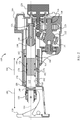
- FIG. 1 depicts a reciprocating saw 100 including an outer housing 102 which includes a handle portion 104, a motor portion 106, and a nose portion 108.
- the handle portion 104 includes a grip 112, a dual-speed switch 114, and a variable speed trigger 116.
- the handle portion 104 is configured to removably receive a battery pack 118 which in some embodiments is replaced by a corded power supply.
- the nose portion 108 is shaped to allow a user to grip the tool 100 while the tool 100 is in use and in some embodiments is made from a rubber material.
- a foot plate assembly 120 is located forwardly of the nose portion 108.
- the motor portion 106 includes a number of ventilation ports 122 which are used to provide cooling air to a motor 124 shown in FIG. 2 .
- the motor 124 rotatably drives an output shaft 126 which is engaged with a gear 128.
- the gear 128 is fixedly connected to a drive shaft 130 which includes an angled portion 132.
- a wobble plate assembly 134 is rotatably positioned on the angled portion 132 and configured to drive a plunger assembly 140 in a reciprocating motion.
- the drive shaft 130 is supported at one end by a needle bearing 136.
- the plunger assembly 140 includes a plunger 142 which is supported by a rear bushing 144.
- a vent 146 is defined through the rear bushing 144.
- a forward end portion 148 of the plunger 142 extends through the nose portion 108 and supports a chuck assembly 150.
- the chuck assembly 150 is configured to removably support a saw blade 152 (see FIG. 1 ).
- the plunger 142 is configured to drive the saw blade 152 along a plunger axis 154.
- the plunger 142 includes an inner wall 160 and an outer wall 162.
- a wiper flange 164 extends outwardly from the outer wall 162 and is sealingly and slidingly engaged with the nose portion 108 by an O-ring 166.
- the nose portion 108, wiper flange 164, and outer wall 162 define a first fluid chamber 170 which extends about the plunger 142 and is in fluid communication with a second fluid chamber 172 defined in part by the inner wall 160 through one or more fluid ports 174.
- the second fluid chamber 172 is further defined by a counterweight 176 located within the plunger 142.
- the counterweight 176 is slidingly and sealingly engaged with the inner wall 160 by one or more O-rings 178.
- FIG. 2 Operation of the reciprocating saw 100 is described with initial reference to FIG. 2 .
- the plunger 142 is at its most rearward location and the counterweight 176 is at its most forward location.
- a user then applies power to the motor 124 from the battery pack 118 by selecting a speed range with the dual-speed switch 114 and depressing the variable speed trigger 116. As power is applied to the motor 124, the output shaft 126 rotates.
- Rotation of the shaft 126 forces the gear 128 to rotate and, since the gear is fixedly connected to the drive shaft 130, the drive shaft 130 rotates as well.
- the wobble plate assembly 134 is constrained against movement orthogonal to the plunger axis 154 by the configuration of the plunger assembly 140. Accordingly, as the drive shaft 130 rotates from the orientation depicted in FIG. 2 to the orientation of FIG. 3 , the top of the wobble plate assembly 134 pivots forwardly, in the direction of the arrow 180 of FIG. 2 .
- Movement of the top of the wobble plate assembly 134 in the direction of the arrow 180 forces the plunger assembly 140 including the plunger 142 to also move in the direction of the arrow 180.
- the wiper flange 164 reduces the volume of the first fluid chamber 170. Consequently, pressure increases within the first fluid chamber 170.
- the increased pressure in the first fluid chamber 170 forces fluid, which in one embodiment is air, out of the first fluid chamber 170, through the fluid ports 174, and into the lower pressure second fluid chamber 172 as indicated by the arrow 182.
- the combined volume of the first fluid chamber 170 and the second fluid chamber 172 remains constant. Since the volume of the first fluid chamber 170 is decreasing, the counterweight 176 is forced to move so as to increase the volume of the second fluid chamber 172. Consequently, as the plunger assembly 140 moves forwardly, the counterweight 176 moves rearwardly, thereby cancelling effects of the forward movement of the plunger assembly 140.
- FIG. 4 depicts a portion of a reciprocating saw 200 which is similar to the reciprocating saw 100.
- the reciprocating saw 200 includes a motor housing portion 206, and a nose housing portion 208.
- a foot plate assembly 210 is located forwardly of the nose portion 208.
- a motor 214 rotatably drives an output shaft 216 which is engaged with a gear 218.
- the gear 218 is fixedly connected to a drive shaft 220 which includes an angled portion 222.
- a wobble plate assembly 224 is rotatably positioned on the angled portion 222 and configured to drive a plunger assembly 230 in a reciprocating motion.
- the drive shaft 220 is supported at one end by a needle bearing 221.
- the plunger assembly 230 includes a plunger 232 which includes an inner wall which defines a rearward first diameter portion 234 and another inner wall which defines a second diameter portion 236 which has a smaller diameter than the first diameter portion 234.
- the first diameter portion 234 and the second diameter portion 236 are separated by a neck portion 238.
- the plunger 232 is slidingly supported by a rear bushing 240 positioned within the first diameter portion 234.
- An O-ring 242 provides a seal between the rear bushing 240 and the first diameter portion 234.
- a forward end portion 244 of the plunger 232 extends through the nose portion 208 and supports a chuck assembly 246.
- the plunger assembly 230 is movable along a plunger axis 248.
- a counterweight 250 is slidingly and sealingly engaged within the second diameter portion 236 by one or more O-rings 252.
- a first fluid chamber 258 is defined by the first diameter portion 234, the rear bushing 240, and the neck portion 238.
- a second fluid chamber 260 is defined by the second diameter portion 236, the counterweight 250, and the neck portion 238.
- the portion of the plunger 232 forward of the counterweight 250 is vented to atmosphere by a vent 262.
- a dust filter (not shown) is provided for the vent 262.
- Operation of the reciprocating saw 200 in one embodiment is substantially the same as the operation of the reciprocating saw 100 up to the initial movement of the plunger 232 along the plunger axis 248 in the direction of the arrow 270 of FIG. 4 .
- the volume of the first fluid chamber 258 is increased. Because the first fluid chamber 258 is sealed at one end by the rear bushing 236, the pressure within the first fluid chamber 258 is decreased.
- Fluid within the second fluid chamber 260 is allowed to flow into the first fluid chamber 258 through the neck portion 238 which functions as a fluid port as indicated by the arrow 272.
- the counterweight 250 provides a seal against fluid flow. Accordingly, the pressure within the second fluid chamber 260 is decreased.
- the pressure within the plunger 232 forward of the counterweight 250 remains constant since the second diameter portion 236 forward of the counterweight 250 is substantially open to atmosphere through the vent 262. A pressure difference is thus created across the counterweight 250 which forces the counterweight 250 to move in the direction of the arrow 274, directly opposite to the arrow 270. Since the volume of the first fluid chamber 258 is increasing, the counterweight 250 is forced to move so as to reduce the volume of the second fluid chamber 260. Thus, the combined volume of the first fluid chamber 258 and the second fluid chamber 260 remains constant.
- the wobble plate assembly 224 has forced the plunger assembly 230 to its most forward position, while the counterweight 250 has been forced rearwardly to its most rearward position.
- the motor 214 continues to rotate, the above described movement of the wobble plate assembly 224 and the plunger assembly 230 is reversed.
- the plunger 232 moves in the direction of the arrow 280, the volume of the first fluid chamber 258 is decreased. Because the first fluid chamber 258 is sealed at one end by the rear bushing 236, the pressure within the first fluid chamber 258 is increased.
- Fluid within the first fluid chamber 258 is allowed to flow into the lower pressure volume of the second fluid chamber 260 through the neck portion 238 which functions as a fluid port as indicated by the arrow 282.
- the counterweight 250 provides a seal against fluid flow. Accordingly, the pressure within the second fluid chamber 260 is increased.
- the pressure within the plunger 232 forward of the counterweight 250 remains constant since the second diameter portion 236 forward of the counterweight 250 is substantially open to atmosphere through the vent 262. A pressure difference is thus created across the counterweight 250 which forces the counterweight 250 to move in the direction of the arrow 284, directly opposite to the arrow 280.
- the vibration of the plunger assembly 230 is offset by movement of the counterweight 250.
- FIG. 6 depicts a portion of a reciprocating saw 300 which is also similar to the reciprocating saw 100, but not according to the invention.
- the reciprocating saw 300 includes a motor housing portion 306, and a nose housing portion 308.
- a foot plate assembly 310 is located forwardly of the nose portion 308.
- a motor 314 rotatably drives an output shaft 316 which is engaged with a gear 318.
- the gear 318 is fixedly connected to a drive shaft 320 which includes an angled portion 322.
- a wobble plate assembly 324 is rotatably positioned on the angled portion 322 and configured to drive a plunger assembly 330 in a reciprocating motion.
- the drive shaft 320 is supported at one end by a needle bearing 321.
- the plunger assembly 330 includes a plunger 332 which includes a rearwardly located large diameter portion 334 and a more forwardly located smaller diameter portion 336.
- the smaller diameter portion 336 includes an inner wall 338 and an outer wall 340.
- the plunger 332 is slidingly supported by a rear bushing 342 positioned within the large diameter portion 334.
- An O-ring 344 provides a seal between the rear bushing 340 and the large diameter portion 334.
- a forward end portion 346 of the plunger 332 extends through the nose portion 308 and supports a chuck assembly 348.
- the plunger assembly 330 is movable along a plunger axis 350.
- the inner wall 338 and the rear bushing 342 define a first fluid chamber 352 which is connected to a second fluid chamber 354 by one or more fluid ports 356.
- the second fluid chamber 354 is defined by the outer wall 340, the nose portion housing 308, and a counterweight 358 which is slidingly and sealingly engaged with both the outer wall 340 and the nose portion housing 308 by one or more O-rings 360.
- the area forward of the counterweight 358 and between the outer wall 340 and the nose portion housing 308 is vented to atmosphere through a vent 362.
- an air filter (not shown) is located on the vent 362.
- Operation of the reciprocating saw 300 in one embodiment is substantially the same as the operation of the reciprocating saw 100 up to the initial movement of the plunger 332 along the plunger axis 350 in the direction of the arrow 370 of FIG. 6 .
- the volume of the first fluid chamber 352 is increased. Because the first fluid chamber 352 is sealed at one end by the rear bushing 342, the pressure within the first fluid chamber 352 is decreased.
- Fluid within the second fluid chamber 354 is allowed to flow into the lower pressure first fluid chamber 352 through the fluid port 356 as indicated by the arrow 372.
- the counterweight 358 provides a seal against fluid flow. Accordingly, the pressure within the second fluid chamber 354 is decreased.
- the pressure within the space between the outer wall 340 and the nose portion housing 308 forward of the counterweight 358 remains constant since the space between the outer wall 340 and the nose portion housing 308 is substantially open to atmosphere through the vent 362.
- a pressure difference is thus created across the counterweight 358 which forces the counterweight 358 to move in the direction of the arrow 374, directly opposite to the arrow 370. Since the volume of the first fluid chamber 352 is increasing, the counterweight 358 is forced to move so as to reduce the volume of the second fluid chamber 354. Thus, the combined volume of the first fluid chamber 352 and the second fluid chamber 354 remains constant.
- the wobble plate assembly 324 has forced the plunger assembly 330 to its most forward position, while the counterweight 358 has been forced rearwardly to its most rearward position.
- the motor 314 continues to rotate, the above described movement of the wobble plate assembly 324 and the plunger assembly 330 is reversed.
- the plunger 332 moves in the direction of the arrow 380, the volume of the first fluid chamber 352 is decreased. Because the first fluid chamber 352 is sealed at one end by the rear bushing 342, the pressure within the first fluid chamber 352 is increased.
- Fluid within the first fluid chamber 352 is allowed to flow into the lower pressure second fluid chamber 354 through the fluid port 356 as indicated by the arrow 382.
- the counterweight 358 provides a seal against fluid flow. Accordingly, the pressure within the second fluid chamber 354 is increased.
- the pressure within the space between the outer wall 340 and the nose portion housing 308 forward of the counterweight 358 remains constant since the space between the outer wall 340 and the nose portion housing 308 forward of the counterweight 358 is substantially open to atmosphere through the vent 362. A pressure difference is thus created across the counterweight 358 which forces the counterweight 358 to move in the direction of the arrow 384, directly opposite to the arrow 380.
- the vibration of the plunger assembly 330 is offset by movement of the counterweight 358.
- FIG. 8 depicts a portion of a reciprocating saw 400 which also provides vibration reduction.
- the reciprocating saw 400 includes a motor housing portion 406, and a nose housing portion 408.
- a foot plate assembly 410 is located forwardly of the nose portion 408.
- a motor 414 rotatably drives an output shaft 416 which is engaged with a gear 418.
- the gear 418 is fixedly connected to a drive shaft 420 which includes an angled portion 422.
- a wobble plate assembly 424 is rotatably positioned on the angled portion 422 and configured to drive a plunger assembly 430 in a reciprocating motion.
- the drive shaft 420 is supported at one end by a needle bearing 421.
- the plunger assembly 430 includes a plunger 432 which includes an inner wall 438 and an outer wall 440.
- the plunger 432 is slidingly supported by a rear bushing 442.
- a forward end portion 446 of the plunger 432 extends through the nose portion 408 and supports a chuck assembly 448.
- the plunger assembly 430 is movable along a plunger axis 450.
- a retaining clip 452 defines a chamber 454 within the plunger 432.
- a counterweight 456 is located within the chamber 454.
- a vent 458 extends along the length of the counterweight 456.
- a first spring 460 is located within the chamber 454 and forwardly of the counterweight 456 while a second spring 462 is located within the chamber 454 and rearwardly of the counterweight 456.
- Operation of the reciprocating saw 400 in one embodiment is substantially the same as the operation of the reciprocating saw 100.
- the main difference is that as the springs 460/462 and the counterweight 456 function as a tuned mass damper. Accordingly, the mass of the counterweight 456 and the spring constants of the springs 460/462 are selected to define a desired mass-spring system with a predetermined natural frequency.
- the predetermined natural frequency is selected to match the value of the stroke rate of the reciprocating tool 400.
- the selected frequency is selected in some embodiments to be a nominal value within the typical range of stroke rates.
- the counterweight 456 oscillates out-of-phase with the movement of the plunger 432 thereby cancelling or absorbing some of the forces used to accelerate and decelerate the plunger 432.
- the vent 458 provides for movement of air from one side of the counterweight 456 to the other side of the counterweight 456 to preclude undesired damping of movement of the counterweight 456.
- the tuned mass system in the embodiment of FIG 8 is located within the plunger 432, in other embodiments, not according to the invention, the counterweight and springs are located outside of the plunger. By positioning the system within the plunger 432, however, a hollow space which has traditionally been dead space is utilized thereby reducing the bulk of the tool 400.
Landscapes
- Engineering & Computer Science (AREA)
- Mechanical Engineering (AREA)
- Sawing (AREA)
Claims (9)
- Outil à mouvement alternatif (100) comprenant :une première chambre de fluide à volume variable (170) ;une seconde chambre de fluide à volume variable (172) en communication fluidique avec la première chambre de fluide à volume variable (170) ;un piston (142) conçu pour modifier le volume de la première chambre de fluide à volume variable (170) par un mouvement généralement dans une première direction (180) le long d'un axe de piston (154) de sorte qu'une partie d'un fluide se déplace de l'une des première et seconde chambres de fluide à volume variable (172) vers l'autre des première et seconde chambres de fluide à volume variable (172) ;un contrepoids (176) conçu de sorte que le mouvement de la partie du fluide résulte en un mouvement du contrepoids (176) généralement dans une seconde direction (184) le long de l'axe de piston, la seconde direction (184) étant opposée à la première direction (180) ; etun ensemble mandrin (150) supporté par le piston (142),le piston (142) comprenant une première paroi intérieure (160) ;la première chambre de fluide à volume variable (170) et/ou la seconde chambre de fluide à volume variable (172) étant définie en partie par la première paroi intérieure (160) ;caractérisé en ce quele contrepoids (176) est situé à l'intérieur du piston (142) ; etle contrepoids (176) vient en prise de manière étanche et coulissante avec la première paroi intérieure (160).
- Outil selon la revendication 1,
la première chambre de fluide à volume variable (170) étant définie en partie par la première paroi intérieure (160) ;
le piston (142) comprenant une seconde paroi intérieure (160) ; et
la seconde chambre de fluide à volume variable (172) étant définie en partie par la seconde paroi intérieure (160). - Outil selon la revendication 2, comprenant en outre :
une partie col située entre la première chambre de fluide à volume variable (170) et la seconde chambre de fluide à volume variable (172). - Outil selon la revendication 3, comprenant en outre :
une douille arrière en prise coulissante et étanche avec la première paroi intérieure (160). - Outil selon la revendication 1,
le piston (142) comprenant une paroi extérieure (162) ;
un orifice à fluide (174) s'étendant entre la première paroi intérieure (160) et la paroi extérieure (162) ;
la seconde chambre de fluide (172) étant définie en partie par la paroi intérieure (160) ; et
la première chambre de fluide (170) étant définie en partie par la paroi extérieure (162). - Outil selon la revendication 5, comprenant en outre :
une bride de raclage s'étendant vers l'extérieur depuis la paroi extérieure (162) et définissant en partie la première chambre de fluide (170). - Outil selon la revendication 6, comprenant en outre :
une douille arrière supportant le piston (142) et comprenant un évent d'air s'étendant à travers celle-ci. - Outil selon la revendication 1,
un orifice à fluide (174) s'étendant entre la première paroi intérieure (160) et la paroi extérieure (162) ;
la seconde chambre de fluide (172) étant définie en partie par la paroi extérieure (162) ; et
la première chambre de fluide étant définie en partie par la paroi intérieure (160). - Outil selon la revendication 8, comprenant en outre :
une douille arrière en prise coulissante et étanche avec le piston (142).
Applications Claiming Priority (2)
| Application Number | Priority Date | Filing Date | Title |
|---|---|---|---|
| US201261747759P | 2012-12-31 | 2012-12-31 | |
| PCT/US2013/078171 WO2014106139A1 (fr) | 2012-12-31 | 2013-12-29 | Outil à mouvement alternatif ayant un contrepoids à entraînement fluidique |
Publications (2)
| Publication Number | Publication Date |
|---|---|
| EP2938465A1 EP2938465A1 (fr) | 2015-11-04 |
| EP2938465B1 true EP2938465B1 (fr) | 2020-03-18 |
Family
ID=49958745
Family Applications (1)
| Application Number | Title | Priority Date | Filing Date |
|---|---|---|---|
| EP13821631.2A Active EP2938465B1 (fr) | 2012-12-31 | 2013-12-29 | Outil à mouvement alternatif ayant un contrepoids à entraînement fluidique |
Country Status (4)
| Country | Link |
|---|---|
| US (1) | US9981372B2 (fr) |
| EP (1) | EP2938465B1 (fr) |
| CN (1) | CN105377510B (fr) |
| WO (1) | WO2014106139A1 (fr) |
Families Citing this family (4)
| Publication number | Priority date | Publication date | Assignee | Title |
|---|---|---|---|---|
| WO2017094412A1 (fr) * | 2015-11-30 | 2017-06-08 | 日立工機株式会社 | Outil à mouvement alternatif |
| CN112970451B (zh) * | 2019-12-02 | 2024-01-30 | 创科无线普通合伙 | 一种电动修枝机 |
| CN214025543U (zh) * | 2020-09-30 | 2021-08-24 | 江苏东成工具科技有限公司 | 往复式电动工具 |
| CN113210728A (zh) * | 2021-04-19 | 2021-08-06 | 江苏东成工具科技有限公司 | 往复式电动工具 |
Family Cites Families (21)
| Publication number | Priority date | Publication date | Assignee | Title |
|---|---|---|---|---|
| US1800465A (en) * | 1927-03-14 | 1931-04-14 | Mccrosky Tool Corp | Power hammer |
| US3241459A (en) * | 1964-05-12 | 1966-03-22 | Gen Motors Corp | Reciprocating tool |
| EP0052507B1 (fr) * | 1980-11-18 | 1985-02-13 | Black & Decker Inc. | Perceuse à percussion |
| US5025562A (en) * | 1990-03-01 | 1991-06-25 | Milwaukee Electric Tool Corporation | Counterbalanced reciprocating mechanism |
| US5079844A (en) | 1990-11-13 | 1992-01-14 | Milwaukee Electric Tool Corporation | Counterbalanced reciprocating mechanism |
| US5218767A (en) * | 1992-04-06 | 1993-06-15 | Wells Andrew J | Fluid powered cutting tool |
| DE19728729C2 (de) * | 1997-07-04 | 2000-11-09 | Wacker Werke Kg | Luftfeder-Schlagwerk mit Luftausgleich |
| DE19851888C1 (de) * | 1998-11-11 | 2000-07-13 | Metabowerke Kg | Bohrhammer |
| JP3976187B2 (ja) * | 2002-11-20 | 2007-09-12 | 株式会社マキタ | ハンマードリル |
| ATE467487T1 (de) | 2003-03-21 | 2010-05-15 | Black & Decker Inc | Schwingungsreduziervorrichtung für kraftbetriebenes werkzeug und solch eine vorrichtung enthaltendes kraftbetriebenes werkzeug |
| DE602004026134D1 (de) | 2003-04-01 | 2010-05-06 | Makita Corp | Kraftwerkzeug |
| US8261851B2 (en) * | 2005-04-11 | 2012-09-11 | Makita Corporation | Electric hammer |
| CN1939660B (zh) * | 2005-09-30 | 2011-08-03 | 苏州宝时得电动工具有限公司 | 电动工具 |
| JP5041575B2 (ja) | 2006-03-07 | 2012-10-03 | 日立工機株式会社 | 打撃工具 |
| CN101062558B (zh) * | 2006-04-29 | 2012-01-25 | 苏州宝时得电动工具有限公司 | 电锤 |
| US7707729B2 (en) | 2007-02-02 | 2010-05-04 | Robert Bosch Gmbh | Drive mechanism for a reciprocating tool |
| US7806201B2 (en) | 2007-07-24 | 2010-10-05 | Makita Corporation | Power tool with dynamic vibration damping |
| DE102007060636A1 (de) | 2007-12-17 | 2009-06-18 | Robert Bosch Gmbh | Elektrohandwerkzeug, insbesondere ein Bohr- und/oder Meißelhammer, mit einer Tilgereinheit |
| JP5214343B2 (ja) | 2008-06-19 | 2013-06-19 | 株式会社マキタ | 作業工具 |
| DE102009027422A1 (de) * | 2009-07-02 | 2011-01-05 | Robert Bosch Gmbh | Vorrichtung zur Reduktion und/oder Kompensation von Vibrationen, insbesondere für eine Handwerkzeugmaschine und zur Verwendung in Handwerkzeugmaschinen |
| JP5496812B2 (ja) | 2010-08-03 | 2014-05-21 | 株式会社マキタ | 作業工具 |
-
2013
- 2013-12-27 US US14/141,553 patent/US9981372B2/en active Active
- 2013-12-29 CN CN201380074070.5A patent/CN105377510B/zh active Active
- 2013-12-29 EP EP13821631.2A patent/EP2938465B1/fr active Active
- 2013-12-29 WO PCT/US2013/078171 patent/WO2014106139A1/fr not_active Ceased
Non-Patent Citations (1)
| Title |
|---|
| None * |
Also Published As
| Publication number | Publication date |
|---|---|
| EP2938465A1 (fr) | 2015-11-04 |
| CN105377510A (zh) | 2016-03-02 |
| US9981372B2 (en) | 2018-05-29 |
| CN105377510B (zh) | 2018-10-30 |
| US20140182871A1 (en) | 2014-07-03 |
| WO2014106139A1 (fr) | 2014-07-03 |
Similar Documents
| Publication | Publication Date | Title |
|---|---|---|
| EP1832394B1 (fr) | Outil d'impact doté d'un mécanisme de contrôle des vibrations | |
| US7766096B2 (en) | Electrical power tool | |
| EP2938465B1 (fr) | Outil à mouvement alternatif ayant un contrepoids à entraînement fluidique | |
| EP1710052B1 (fr) | Outil de percussion électrique avec moyens de limitation des vibrations | |
| US9815185B2 (en) | Power tool | |
| JP2003011073A (ja) | ハンマ | |
| CN102458777A (zh) | 作业工具 | |
| JP2017205864A (ja) | 流体力学的圧縮または切断工具 | |
| EP2938452B1 (fr) | Outil à mouvement alternatif avec bague interne de guidage et méthode d'utilisation d'un tel outil | |
| US10272506B2 (en) | Reciprocating tool with linear guides | |
| EP2969341B1 (fr) | Outil à mouvement alternatif avec ensemble de sollicitation | |
| WO2018219325A1 (fr) | Outil électrique | |
| JP5997038B2 (ja) | 手持ち式動力工具 | |
| JP5327726B2 (ja) | 打撃工具 | |
| JP2025004948A (ja) | 打撃工具 | |
| JP2014233769A (ja) | 往復動工具 | |
| CN111390839A (zh) | 一种芯体可往复式冲击的手持式工具机及其使用方法 |
Legal Events
| Date | Code | Title | Description |
|---|---|---|---|
| PUAI | Public reference made under article 153(3) epc to a published international application that has entered the european phase |
Free format text: ORIGINAL CODE: 0009012 |
|
| 17P | Request for examination filed |
Effective date: 20150731 |
|
| AK | Designated contracting states |
Kind code of ref document: A1 Designated state(s): AL AT BE BG CH CY CZ DE DK EE ES FI FR GB GR HR HU IE IS IT LI LT LU LV MC MK MT NL NO PL PT RO RS SE SI SK SM TR |
|
| AX | Request for extension of the european patent |
Extension state: BA ME |
|
| RAP1 | Party data changed (applicant data changed or rights of an application transferred) |
Owner name: ROBERT BOSCH GMBH |
|
| DAX | Request for extension of the european patent (deleted) | ||
| GRAP | Despatch of communication of intention to grant a patent |
Free format text: ORIGINAL CODE: EPIDOSNIGR1 |
|
| STAA | Information on the status of an ep patent application or granted ep patent |
Free format text: STATUS: GRANT OF PATENT IS INTENDED |
|
| INTG | Intention to grant announced |
Effective date: 20191210 |
|
| GRAS | Grant fee paid |
Free format text: ORIGINAL CODE: EPIDOSNIGR3 |
|
| GRAA | (expected) grant |
Free format text: ORIGINAL CODE: 0009210 |
|
| STAA | Information on the status of an ep patent application or granted ep patent |
Free format text: STATUS: THE PATENT HAS BEEN GRANTED |
|
| AK | Designated contracting states |
Kind code of ref document: B1 Designated state(s): AL AT BE BG CH CY CZ DE DK EE ES FI FR GB GR HR HU IE IS IT LI LT LU LV MC MK MT NL NO PL PT RO RS SE SI SK SM TR |
|
| REG | Reference to a national code |
Ref country code: GB Ref legal event code: FG4D |
|
| REG | Reference to a national code |
Ref country code: DE Ref legal event code: R096 Ref document number: 602013067011 Country of ref document: DE |
|
| REG | Reference to a national code |
Ref country code: AT Ref legal event code: REF Ref document number: 1245371 Country of ref document: AT Kind code of ref document: T Effective date: 20200415 Ref country code: IE Ref legal event code: FG4D |
|
| RAP2 | Party data changed (patent owner data changed or rights of a patent transferred) |
Owner name: ROBERT BOSCH GMBH |
|
| PG25 | Lapsed in a contracting state [announced via postgrant information from national office to epo] |
Ref country code: NO Free format text: LAPSE BECAUSE OF FAILURE TO SUBMIT A TRANSLATION OF THE DESCRIPTION OR TO PAY THE FEE WITHIN THE PRESCRIBED TIME-LIMIT Effective date: 20200618 Ref country code: FI Free format text: LAPSE BECAUSE OF FAILURE TO SUBMIT A TRANSLATION OF THE DESCRIPTION OR TO PAY THE FEE WITHIN THE PRESCRIBED TIME-LIMIT Effective date: 20200318 Ref country code: RS Free format text: LAPSE BECAUSE OF FAILURE TO SUBMIT A TRANSLATION OF THE DESCRIPTION OR TO PAY THE FEE WITHIN THE PRESCRIBED TIME-LIMIT Effective date: 20200318 |
|
| REG | Reference to a national code |
Ref country code: NL Ref legal event code: MP Effective date: 20200318 |
|
| PG25 | Lapsed in a contracting state [announced via postgrant information from national office to epo] |
Ref country code: HR Free format text: LAPSE BECAUSE OF FAILURE TO SUBMIT A TRANSLATION OF THE DESCRIPTION OR TO PAY THE FEE WITHIN THE PRESCRIBED TIME-LIMIT Effective date: 20200318 Ref country code: GR Free format text: LAPSE BECAUSE OF FAILURE TO SUBMIT A TRANSLATION OF THE DESCRIPTION OR TO PAY THE FEE WITHIN THE PRESCRIBED TIME-LIMIT Effective date: 20200619 Ref country code: BG Free format text: LAPSE BECAUSE OF FAILURE TO SUBMIT A TRANSLATION OF THE DESCRIPTION OR TO PAY THE FEE WITHIN THE PRESCRIBED TIME-LIMIT Effective date: 20200618 Ref country code: SE Free format text: LAPSE BECAUSE OF FAILURE TO SUBMIT A TRANSLATION OF THE DESCRIPTION OR TO PAY THE FEE WITHIN THE PRESCRIBED TIME-LIMIT Effective date: 20200318 Ref country code: LV Free format text: LAPSE BECAUSE OF FAILURE TO SUBMIT A TRANSLATION OF THE DESCRIPTION OR TO PAY THE FEE WITHIN THE PRESCRIBED TIME-LIMIT Effective date: 20200318 |
|
| REG | Reference to a national code |
Ref country code: LT Ref legal event code: MG4D |
|
| PG25 | Lapsed in a contracting state [announced via postgrant information from national office to epo] |
Ref country code: NL Free format text: LAPSE BECAUSE OF FAILURE TO SUBMIT A TRANSLATION OF THE DESCRIPTION OR TO PAY THE FEE WITHIN THE PRESCRIBED TIME-LIMIT Effective date: 20200318 |
|
| PG25 | Lapsed in a contracting state [announced via postgrant information from national office to epo] |
Ref country code: EE Free format text: LAPSE BECAUSE OF FAILURE TO SUBMIT A TRANSLATION OF THE DESCRIPTION OR TO PAY THE FEE WITHIN THE PRESCRIBED TIME-LIMIT Effective date: 20200318 Ref country code: PT Free format text: LAPSE BECAUSE OF FAILURE TO SUBMIT A TRANSLATION OF THE DESCRIPTION OR TO PAY THE FEE WITHIN THE PRESCRIBED TIME-LIMIT Effective date: 20200812 Ref country code: SM Free format text: LAPSE BECAUSE OF FAILURE TO SUBMIT A TRANSLATION OF THE DESCRIPTION OR TO PAY THE FEE WITHIN THE PRESCRIBED TIME-LIMIT Effective date: 20200318 Ref country code: RO Free format text: LAPSE BECAUSE OF FAILURE TO SUBMIT A TRANSLATION OF THE DESCRIPTION OR TO PAY THE FEE WITHIN THE PRESCRIBED TIME-LIMIT Effective date: 20200318 Ref country code: CZ Free format text: LAPSE BECAUSE OF FAILURE TO SUBMIT A TRANSLATION OF THE DESCRIPTION OR TO PAY THE FEE WITHIN THE PRESCRIBED TIME-LIMIT Effective date: 20200318 Ref country code: IS Free format text: LAPSE BECAUSE OF FAILURE TO SUBMIT A TRANSLATION OF THE DESCRIPTION OR TO PAY THE FEE WITHIN THE PRESCRIBED TIME-LIMIT Effective date: 20200718 Ref country code: SK Free format text: LAPSE BECAUSE OF FAILURE TO SUBMIT A TRANSLATION OF THE DESCRIPTION OR TO PAY THE FEE WITHIN THE PRESCRIBED TIME-LIMIT Effective date: 20200318 Ref country code: LT Free format text: LAPSE BECAUSE OF FAILURE TO SUBMIT A TRANSLATION OF THE DESCRIPTION OR TO PAY THE FEE WITHIN THE PRESCRIBED TIME-LIMIT Effective date: 20200318 |
|
| REG | Reference to a national code |
Ref country code: AT Ref legal event code: MK05 Ref document number: 1245371 Country of ref document: AT Kind code of ref document: T Effective date: 20200318 |
|
| REG | Reference to a national code |
Ref country code: DE Ref legal event code: R097 Ref document number: 602013067011 Country of ref document: DE |
|
| PLBE | No opposition filed within time limit |
Free format text: ORIGINAL CODE: 0009261 |
|
| STAA | Information on the status of an ep patent application or granted ep patent |
Free format text: STATUS: NO OPPOSITION FILED WITHIN TIME LIMIT |
|
| PG25 | Lapsed in a contracting state [announced via postgrant information from national office to epo] |
Ref country code: AT Free format text: LAPSE BECAUSE OF FAILURE TO SUBMIT A TRANSLATION OF THE DESCRIPTION OR TO PAY THE FEE WITHIN THE PRESCRIBED TIME-LIMIT Effective date: 20200318 Ref country code: IT Free format text: LAPSE BECAUSE OF FAILURE TO SUBMIT A TRANSLATION OF THE DESCRIPTION OR TO PAY THE FEE WITHIN THE PRESCRIBED TIME-LIMIT Effective date: 20200318 Ref country code: DK Free format text: LAPSE BECAUSE OF FAILURE TO SUBMIT A TRANSLATION OF THE DESCRIPTION OR TO PAY THE FEE WITHIN THE PRESCRIBED TIME-LIMIT Effective date: 20200318 Ref country code: ES Free format text: LAPSE BECAUSE OF FAILURE TO SUBMIT A TRANSLATION OF THE DESCRIPTION OR TO PAY THE FEE WITHIN THE PRESCRIBED TIME-LIMIT Effective date: 20200318 |
|
| 26N | No opposition filed |
Effective date: 20201221 |
|
| PG25 | Lapsed in a contracting state [announced via postgrant information from national office to epo] |
Ref country code: PL Free format text: LAPSE BECAUSE OF FAILURE TO SUBMIT A TRANSLATION OF THE DESCRIPTION OR TO PAY THE FEE WITHIN THE PRESCRIBED TIME-LIMIT Effective date: 20200318 |
|
| PG25 | Lapsed in a contracting state [announced via postgrant information from national office to epo] |
Ref country code: SI Free format text: LAPSE BECAUSE OF FAILURE TO SUBMIT A TRANSLATION OF THE DESCRIPTION OR TO PAY THE FEE WITHIN THE PRESCRIBED TIME-LIMIT Effective date: 20200318 |
|
| REG | Reference to a national code |
Ref country code: CH Ref legal event code: PL |
|
| GBPC | Gb: european patent ceased through non-payment of renewal fee |
Effective date: 20201229 |
|
| PG25 | Lapsed in a contracting state [announced via postgrant information from national office to epo] |
Ref country code: MC Free format text: LAPSE BECAUSE OF FAILURE TO SUBMIT A TRANSLATION OF THE DESCRIPTION OR TO PAY THE FEE WITHIN THE PRESCRIBED TIME-LIMIT Effective date: 20200318 |
|
| REG | Reference to a national code |
Ref country code: BE Ref legal event code: MM Effective date: 20201231 |
|
| PG25 | Lapsed in a contracting state [announced via postgrant information from national office to epo] |
Ref country code: IE Free format text: LAPSE BECAUSE OF NON-PAYMENT OF DUE FEES Effective date: 20201229 Ref country code: LU Free format text: LAPSE BECAUSE OF NON-PAYMENT OF DUE FEES Effective date: 20201229 |
|
| PG25 | Lapsed in a contracting state [announced via postgrant information from national office to epo] |
Ref country code: CH Free format text: LAPSE BECAUSE OF NON-PAYMENT OF DUE FEES Effective date: 20201231 Ref country code: GB Free format text: LAPSE BECAUSE OF NON-PAYMENT OF DUE FEES Effective date: 20201229 Ref country code: LI Free format text: LAPSE BECAUSE OF NON-PAYMENT OF DUE FEES Effective date: 20201231 |
|
| PG25 | Lapsed in a contracting state [announced via postgrant information from national office to epo] |
Ref country code: TR Free format text: LAPSE BECAUSE OF FAILURE TO SUBMIT A TRANSLATION OF THE DESCRIPTION OR TO PAY THE FEE WITHIN THE PRESCRIBED TIME-LIMIT Effective date: 20200318 Ref country code: MT Free format text: LAPSE BECAUSE OF FAILURE TO SUBMIT A TRANSLATION OF THE DESCRIPTION OR TO PAY THE FEE WITHIN THE PRESCRIBED TIME-LIMIT Effective date: 20200318 Ref country code: CY Free format text: LAPSE BECAUSE OF FAILURE TO SUBMIT A TRANSLATION OF THE DESCRIPTION OR TO PAY THE FEE WITHIN THE PRESCRIBED TIME-LIMIT Effective date: 20200318 |
|
| PG25 | Lapsed in a contracting state [announced via postgrant information from national office to epo] |
Ref country code: MK Free format text: LAPSE BECAUSE OF FAILURE TO SUBMIT A TRANSLATION OF THE DESCRIPTION OR TO PAY THE FEE WITHIN THE PRESCRIBED TIME-LIMIT Effective date: 20200318 Ref country code: AL Free format text: LAPSE BECAUSE OF FAILURE TO SUBMIT A TRANSLATION OF THE DESCRIPTION OR TO PAY THE FEE WITHIN THE PRESCRIBED TIME-LIMIT Effective date: 20200318 |
|
| PG25 | Lapsed in a contracting state [announced via postgrant information from national office to epo] |
Ref country code: BE Free format text: LAPSE BECAUSE OF NON-PAYMENT OF DUE FEES Effective date: 20201231 |
|
| PGFP | Annual fee paid to national office [announced via postgrant information from national office to epo] |
Ref country code: FR Payment date: 20221219 Year of fee payment: 10 |
|
| PG25 | Lapsed in a contracting state [announced via postgrant information from national office to epo] |
Ref country code: FR Free format text: LAPSE BECAUSE OF NON-PAYMENT OF DUE FEES Effective date: 20231231 |
|
| PG25 | Lapsed in a contracting state [announced via postgrant information from national office to epo] |
Ref country code: FR Free format text: LAPSE BECAUSE OF NON-PAYMENT OF DUE FEES Effective date: 20231231 |
|
| PGFP | Annual fee paid to national office [announced via postgrant information from national office to epo] |
Ref country code: DE Payment date: 20260223 Year of fee payment: 13 |