EP2938497B1 - Procédé pour imprimer des impressions de calibrage, procédés de calibrage et des imprimants - Google Patents
Procédé pour imprimer des impressions de calibrage, procédés de calibrage et des imprimants Download PDFInfo
- Publication number
- EP2938497B1 EP2938497B1 EP13702960.9A EP13702960A EP2938497B1 EP 2938497 B1 EP2938497 B1 EP 2938497B1 EP 13702960 A EP13702960 A EP 13702960A EP 2938497 B1 EP2938497 B1 EP 2938497B1
- Authority
- EP
- European Patent Office
- Prior art keywords
- calibration pattern
- array
- pattern portion
- printing
- Prior art date
- Legal status (The legal status is an assumption and is not a legal conclusion. Google has not performed a legal analysis and makes no representation as to the accuracy of the status listed.)
- Active
Links
- 238000007639 printing Methods 0.000 title claims description 108
- 238000000034 method Methods 0.000 title claims description 60
- 239000000758 substrate Substances 0.000 claims description 45
- 230000008859 change Effects 0.000 claims description 5
- 230000001419 dependent effect Effects 0.000 claims description 3
- 230000004913 activation Effects 0.000 claims 1
- 239000013256 coordination polymer Substances 0.000 description 16
- 230000007547 defect Effects 0.000 description 13
- 230000008569 process Effects 0.000 description 10
- 238000010586 diagram Methods 0.000 description 8
- 238000005259 measurement Methods 0.000 description 8
- 238000001514 detection method Methods 0.000 description 7
- 238000012937 correction Methods 0.000 description 5
- 238000013459 approach Methods 0.000 description 4
- 230000000694 effects Effects 0.000 description 4
- 238000004458 analytical method Methods 0.000 description 2
- 238000012512 characterization method Methods 0.000 description 2
- 230000007613 environmental effect Effects 0.000 description 2
- 238000007641 inkjet printing Methods 0.000 description 2
- 238000004519 manufacturing process Methods 0.000 description 2
- 230000007246 mechanism Effects 0.000 description 2
- 230000007723 transport mechanism Effects 0.000 description 2
- 230000009471 action Effects 0.000 description 1
- 230000003213 activating effect Effects 0.000 description 1
- 238000007792 addition Methods 0.000 description 1
- 238000004364 calculation method Methods 0.000 description 1
- 239000011111 cardboard Substances 0.000 description 1
- 239000003086 colorant Substances 0.000 description 1
- 230000006870 function Effects 0.000 description 1
- 238000010438 heat treatment Methods 0.000 description 1
- 239000000463 material Substances 0.000 description 1
- 239000000123 paper Substances 0.000 description 1
- 239000004033 plastic Substances 0.000 description 1
- 229920003023 plastic Polymers 0.000 description 1
- 238000012545 processing Methods 0.000 description 1
- 230000035945 sensitivity Effects 0.000 description 1
- 239000007787 solid Substances 0.000 description 1
- 239000004753 textile Substances 0.000 description 1
Images






Classifications
-
- B—PERFORMING OPERATIONS; TRANSPORTING
- B41—PRINTING; LINING MACHINES; TYPEWRITERS; STAMPS
- B41J—TYPEWRITERS; SELECTIVE PRINTING MECHANISMS, i.e. MECHANISMS PRINTING OTHERWISE THAN FROM A FORME; CORRECTION OF TYPOGRAPHICAL ERRORS
- B41J2/00—Typewriters or selective printing mechanisms characterised by the printing or marking process for which they are designed
- B41J2/005—Typewriters or selective printing mechanisms characterised by the printing or marking process for which they are designed characterised by bringing liquid or particles selectively into contact with a printing material
- B41J2/01—Ink jet
- B41J2/015—Ink jet characterised by the jet generation process
- B41J2/04—Ink jet characterised by the jet generation process generating single droplets or particles on demand
- B41J2/045—Ink jet characterised by the jet generation process generating single droplets or particles on demand by pressure, e.g. electromechanical transducers
- B41J2/04501—Control methods or devices therefor, e.g. driver circuits, control circuits
- B41J2/04505—Control methods or devices therefor, e.g. driver circuits, control circuits aiming at correcting alignment
-
- B—PERFORMING OPERATIONS; TRANSPORTING
- B41—PRINTING; LINING MACHINES; TYPEWRITERS; STAMPS
- B41J—TYPEWRITERS; SELECTIVE PRINTING MECHANISMS, i.e. MECHANISMS PRINTING OTHERWISE THAN FROM A FORME; CORRECTION OF TYPOGRAPHICAL ERRORS
- B41J2/00—Typewriters or selective printing mechanisms characterised by the printing or marking process for which they are designed
- B41J2/005—Typewriters or selective printing mechanisms characterised by the printing or marking process for which they are designed characterised by bringing liquid or particles selectively into contact with a printing material
- B41J2/01—Ink jet
- B41J2/015—Ink jet characterised by the jet generation process
- B41J2/04—Ink jet characterised by the jet generation process generating single droplets or particles on demand
- B41J2/045—Ink jet characterised by the jet generation process generating single droplets or particles on demand by pressure, e.g. electromechanical transducers
- B41J2/04501—Control methods or devices therefor, e.g. driver circuits, control circuits
- B41J2/04586—Control methods or devices therefor, e.g. driver circuits, control circuits controlling heads of a type not covered by groups B41J2/04575 - B41J2/04585, or of an undefined type
-
- B—PERFORMING OPERATIONS; TRANSPORTING
- B41—PRINTING; LINING MACHINES; TYPEWRITERS; STAMPS
- B41J—TYPEWRITERS; SELECTIVE PRINTING MECHANISMS, i.e. MECHANISMS PRINTING OTHERWISE THAN FROM A FORME; CORRECTION OF TYPOGRAPHICAL ERRORS
- B41J2/00—Typewriters or selective printing mechanisms characterised by the printing or marking process for which they are designed
- B41J2/005—Typewriters or selective printing mechanisms characterised by the printing or marking process for which they are designed characterised by bringing liquid or particles selectively into contact with a printing material
- B41J2/01—Ink jet
- B41J2/21—Ink jet for multi-colour printing
- B41J2/2132—Print quality control characterised by dot disposition, e.g. for reducing white stripes or banding
- B41J2/2142—Detection of malfunctioning nozzles
-
- B—PERFORMING OPERATIONS; TRANSPORTING
- B41—PRINTING; LINING MACHINES; TYPEWRITERS; STAMPS
- B41J—TYPEWRITERS; SELECTIVE PRINTING MECHANISMS, i.e. MECHANISMS PRINTING OTHERWISE THAN FROM A FORME; CORRECTION OF TYPOGRAPHICAL ERRORS
- B41J2/00—Typewriters or selective printing mechanisms characterised by the printing or marking process for which they are designed
- B41J2/005—Typewriters or selective printing mechanisms characterised by the printing or marking process for which they are designed characterised by bringing liquid or particles selectively into contact with a printing material
- B41J2/01—Ink jet
- B41J2/21—Ink jet for multi-colour printing
- B41J2/2132—Print quality control characterised by dot disposition, e.g. for reducing white stripes or banding
- B41J2/2146—Print quality control characterised by dot disposition, e.g. for reducing white stripes or banding for line print heads
-
- B—PERFORMING OPERATIONS; TRANSPORTING
- B41—PRINTING; LINING MACHINES; TYPEWRITERS; STAMPS
- B41J—TYPEWRITERS; SELECTIVE PRINTING MECHANISMS, i.e. MECHANISMS PRINTING OTHERWISE THAN FROM A FORME; CORRECTION OF TYPOGRAPHICAL ERRORS
- B41J29/00—Details of, or accessories for, typewriters or selective printing mechanisms not otherwise provided for
- B41J29/38—Drives, motors, controls or automatic cut-off devices for the entire printing mechanism
- B41J29/393—Devices for controlling or analysing the entire machine ; Controlling or analysing mechanical parameters involving printing of test patterns
-
- B—PERFORMING OPERATIONS; TRANSPORTING
- B41—PRINTING; LINING MACHINES; TYPEWRITERS; STAMPS
- B41J—TYPEWRITERS; SELECTIVE PRINTING MECHANISMS, i.e. MECHANISMS PRINTING OTHERWISE THAN FROM A FORME; CORRECTION OF TYPOGRAPHICAL ERRORS
- B41J29/00—Details of, or accessories for, typewriters or selective printing mechanisms not otherwise provided for
- B41J29/38—Drives, motors, controls or automatic cut-off devices for the entire printing mechanism
- B41J29/393—Devices for controlling or analysing the entire machine ; Controlling or analysing mechanical parameters involving printing of test patterns
- B41J2029/3935—Devices for controlling or analysing the entire machine ; Controlling or analysing mechanical parameters involving printing of test patterns by means of printed test patterns
Definitions
- Some printing devices include components designed to detect and compensate for printing irregularities, for example by printing a calibration pattern, by automatically detecting and analysing the printed calibration pattern and then performing some compensation operation based on the result of the analysis.
- the component used for detecting the printed calibration pattern has a limited resolution and, in particular, cannot accurately detect irregularities that are smaller than a certain size. For example, this may be the case for the densitometers used in some printing devices. However, the human eye may still be able to detect these small irregularities.
- Another alternative approach would be to make a detailed measurement of the printing irregularities produced by a printing device at the stage where the device is being manufactured, and to build into the printing device a precalculated correction or compensation.
- a predetermined correction may not be adequate to compensate for the printing irregularity in the case where the printing error varies in a dynamic manner, for example based on environmental factors, printing speed, and so on.
- PWA printing devices Page wide array printing devices
- EP 1764996 discloses such a page wide array printing device. It is common for PWA printing devices to implement one-pass printing. When a PWA printing device uses a scanning element (e.g. a densitometer) that is not capable of accurately detecting small irregularities produced during one-pass printing but which are still visible to the human eye, the user may consider the quality of the printed image to be inadequate.
- a scanning element e.g. a densitometer
- printing device or printer will be used generically for devices which can produce printed output, irrespective of whether the device is a printer, a photocopier, a facsimile machine, an all-in-one apparatus, etc.
- Fig.1 schematically shows an inkjet printing device 1 which is an example of a printing device in which the present invention may be implemented.
- the printing device 1 is a page wide array printer and it has a printbar 3 with an array 5 of print nozzles extending in the widthwise direction of the printer so as to be able to print simultaneously over the full width of a page of a substrate or medium S.
- the substrate S may take any convenient form including but not limited to paper, cardboard, plastics or textiles material, in sheet form, in web form, and so on.
- the print nozzles are provided on several print dies D and in this example the print dies are arranged on the printbar in two staggered rows.
- Fig.1 only one row of print dies is represented and only three dies are shown but it should be mentioned that any convenient number of print dies may be used.
- Ink is supplied to the print nozzles from a reservoir (not shown) and is dispensed by any convenient mechanism (for example, using heating, using piezoelectric effects, and so on) when the nozzles are activated.
- the print nozzles of the array 5 are activated under the control of a print controller 7 which is connected to the print nozzles by a connector 8 which may take any convenient form, for example a flexible printed circuit board.
- the printer of Fig.1 has a printbar 3 that is designed so that the nozzle array 5 can be moved in the widthwise direction of the printer, as illustrated by the arrow A in Fig.1 .
- a printbar-position controller 9 controls the position of the printbar in the widthwise direction of the printer. Any convenient positioning mechanism may be used to position the printbar in a desired position in the widthwise direction under the control of the printbar-position controller 9.
- a control unit 10 controls the overall operation of the printer 1 and, in particular, controls the print controller 7 and the printbar-position controller 9 during calibration-pattern printing methods to be described later.
- the printer 1 also includes a scanning-type sensor 12 whose detecting element is a relatively low-cost densitometer.
- the control unit 10 is connected to the scanner 12 and receives measurement output from the scanner 12.
- the control unit 10 may be implemented in any convenient manner for example using one or more processors cooperating with memory (not shown).
- the printer 1 includes a media transport mechanism (not shown) for transporting a substrate through the printer along a printing path.
- the media transport mechanism may allow a substrate to be advanced through the printer in a first direction and retreated through the printer in a direction opposite to the direction of advance.
- Fig.1 One example of a type of small printing irregularity that may affect images printed by printing devices such as that of Fig.1 , which have the printing nozzles provided on plural print dies, will be explained with reference to Figs. 2 to 4 , to illustrate a case where a scanning device cannot properly detect the small irregularities. Additional defects will be discussed in relation to Fig.5 .
- a printhead having plural dies and which is provided with printing data to print a uniform block of a constant hue tends to produce, on the substrate, a printed block that has some variability, instead of being entirely uniform.
- a reason for this is that a number of print nozzles at the end of a print die tend to print smaller ink drops than the medial print nozzles that are situated closer to the centre of the print die. It will be seen in Fig.2 that the printed image of the uniform block of colour has lighter bands at positions that correspond to the ends of the print dies.
- the intensity measured as the scanner 12 pans across the printed image is as represented by the dotted line in Fig.3 .
- the actual variation in intensity is as illustrated by the solid lines in Fig.3 and it is considerably greater in amount than that measured by the sensor 12.
- the intensity measured by the scanner 12 may be compared with a reference value (e.g. the intensity measured at print locations away from the ends of the print dies) to determine print nozzle locations where the printed output does not correspond to the desired output, and a correction factor may be determined for use during subsequent printing operations involving the print nozzle locations in question.
- a correction or compensation operation is performed based on the output from the sensor 12 that is illustrated in Fig.3 then the true error will not be accurately compensated and irregularities may still be visible in the images printed by the printer.
- a high performance scanning device can measure intensity variations of this kind accurately, as illustrated by the trace portions shown in Fig.4 , which were produced by a high-performance scanner. However, the cost of the printer 1 would be increased if the scanner 12 were to be replaced by a high-performance scanning device of this type.
- Fig.5 illustrates a portion of an image printed by a printer having several print dies based on printing data that represents a solid block of constant hue. In this printed image certain defects are visible including alignment defects.
- the appropriate calibration pattern to print when seeking to detect a printing defect may vary dependent on the nature of the defect to be detected. For example, when seeking to detect alignment defects it may be appropriate to print an interference pattern made up of a first calibration pattern portion printed by a first print die and a second calibration pattern portion printed by a different print die after the print dies have been moved. However, irrespective of the nature of the calibration pattern, if a defect in the printed calibration pattern is too small to be accurately measured by the applicable scanning component in the printer then the defect will not be accurately compensated/corrected.
- Fig.6 is a flow diagram illustrating the processes involved in the method according to this example
- Fig.7 is a diagram illustrating how the positioning of an array of print nozzles changes in the method of this example, and the effect this produces on the printed calibration pattern.
- Figs.7A to 7E illustrate different aspects of the method.
- the calibration-pattern printing method of this example includes a process S10 of printing one or more calibration pattern portions by respective first portions of the nozzle array.
- the nozzle array shown partially in Figs.7A and 7B includes two rows of staggered nozzles and a group of four adjacent nozzles (circled by a ring NG in Fig.7A ) constitute a single "first portion" of the nozzle array that is controlled to print a single calibration pattern portion CP in step S10.
- a set of "first portions" of the nozzle array may be operated so that they all print a respective first calibration pattern during step S10. An example of that type will be discussed below with reference to Figs.8 to 10 .
- the different "first portions" of the nozzle array may be driven to print respective first calibration portions that are different from each other.
- Fig.7C shows a calibration pattern portion CP in the form of a block that is printed by the first portion of the nozzle array (i.e. nozzle group NG) during the step S10 according to the example of Fig.6 . It will be noticed that the printbar is in a first position (designated POS1) in the widthwise direction of the printer during the printing operation of S10, as illustrated in Fig.7A .
- the print controller 7 activates the identified four adjacent print nozzles NG so that they print a calibration pattern portion CP of desired characteristics (shape, hue, etc.) in step S10, and the printbar-position controller 9 controls the printbar to be in position POS1 during this printing operation: these operations of the print controller 7 and printbar-position controller 9 may be controlled by the control unit 10.
- the dotted arrow drawn from Fig.7A to Fig.7C illustrates that the nozzle group NG prints the calibration pattern portion CP.
- step S11 of the method according to this example the relative position of the nozzle array and the substrate in the widthwise (transverse) direction of the printer is changed.
- the change in relative position is achieved by moving the nozzle array to the position POS2 illustrated in Fig.7B , while the widthwise position of the substrate is not changed.
- This lateral shift of the printbar may be achieved using the printbar-position controller 9 illustrated in Fig.1 under the control of the control unit 10.
- the first portion NG of the nozzle array is activated again so as to print a further calibration pattern portion FCP in step S12 of the Fig.6 method.
- the dotted arrow drawn from Fig.7B to Fig.7D illustrates that the nozzle group NG prints the calibration pattern portion CP.
- the calibration pattern portion CP and further calibration pattern portion FCP printed by the same first portion of the nozzle array have the same shape and size, but the invention is not limited to that case: in some cases the calibration pattern portion CP and further calibration pattern portion FCP printed by the same first portion of the nozzle array may be different from one another.
- the calibration pattern portion CP and further calibration pattern portion FCP are printed by the same group of nozzles NG in a manner whereby they are contiguous in the widthwise direction of the printer, that is, the edges of the two pattern portions touch, with negligible overlap and negligible empty space between them so that they form, in effect, a widthwise-enlarged calibration pattern portion.
- the widthwise-enlarged calibration pattern portion formed of CP+FCP printed on the substrate can be scanned and its properties analysed and this will provide information about the print characteristics of the nozzle group NG which, normally, prints over a substrate region of considerably smaller width. This enlargement of the printing pattern produced by a given portion of the nozzles may enable printing defects caused by that nozzle portion to be detected more accurately by a scanner or other detection device.
- a contiguous disposition of the calibration pattern portion CP and further calibration pattern portion FCP printed by the same nozzle group NG in steps S10 and S12 is obtained by setting the distance between POS1 and POS2 in the widthwise direction of the printer to match the width of the calibration pattern portion printed by the nozzle group in question.
- the accuracy of the matching depends on the accuracy of the relative positioning of the nozzle array and the substrate in the widthwise direction of the printer.
- steps S11 and S12 of the method of Fig.6 may be repeated (as illustrated by the dotted arrow) as many times as is necessary to produce an enlarged calibration pattern portion of a width sufficient to allow the print characteristics of this portion to be accurately determined by the scanner.
- Successively-printed calibration pattern portions and further calibration pattern portions join up in the widthwise direction to form the overall enlarged calibration pattern portion.
- the adjacent calibration pattern portions printed by the same "first group" of nozzles are aligned in the longitudinal direction of the printer; in other words, the top and bottom edges of CP and FCP are aligned.
- a simple manner for achieving this longitudinal alignment is to move the substrate back through the printer between steps S10 and S12 of Fig.6 , reversing the direction of travel of the substrate, so that the substrate is in the same position in the longitudinal direction of the printer at the start of each of the printing operations in steps S10 and S12.
- An equivalent approach for returning the substrate to the start position is to move the nozzle array relative to the substrate in the longitudinal direction in between steps S10 and S12.
- Another alternative for achieving longitudinal alignment consists in using two-directional printing, that is, moving the substrate through the printer in the longitudinal direction in a first sense (e.g. to print the block CP starting from the top thereof as illustrated in Fig.7 ) during printing of the calibration pattern portion CP in step S10 and then moving the substrate through the printer in the longitudinal direction in the opposite sense (e.g. to print the block FCP starting from the bottom thereof as illustrated in Fig.7 ) during printing of the calibration pattern portion FCP in step S12.
- a first sense e.g. to print the block CP starting from the top thereof as illustrated in Fig.7
- the opposite sense e.g. to print the block FCP starting from the bottom thereof as illustrated in Fig.7
- Fig.7D illustrates the case where the relative position of the nozzle array and substrate is controlled during printing of the calibration pattern portions so that there is full longitudinal alignment of the calibration pattern portion CP and the further calibration pattern portion FCP.
- the longitudinal positions of the nozzle array and substrate may be controlled during the printing operations of S10 and S12 so that there is only partial alignment of the printed calibration pattern portion CP' and the further calibration pattern portion FCP' in the longitudinal direction as illustrated in Fig.7E .
- the contiguous calibration pattern portions CP' and FCP' form a region of enlarged width which can be used to derive printing characteristic data regarding a nozzle portion that normally prints over a relatively smaller width.
- a minimum feature size that can be detected properly by scanner devices not only in the widthwise direction of the printed page but also in the longitudinal direction.
- the extent of the enlarged calibration pattern portion in the longitudinal direction matches or exceeds this minimum feature size then the enlarged calibration pattern portion can be properly detected by the scanner.
- An enlarged calibration pattern portion extending approximately 0.3 inches or more in the longitudinal direction is an example of a portion which can be detected by certain scanner devices.
- Fig.8 is a flow diagram illustrating the processes involved in the method according to this example
- Fig.9 is a series of diagrams illustrating how a printed calibration pattern may build up during implementation of the method.
- the calibration-pattern printing method of this example includes a process S80 of printing first and second calibration pattern portions by first and second portions of the nozzle array.
- the nozzle array includes print nozzles on print dies that are arranged in two staggered rows, groups of nozzles at the ends of the dies constitute a set of "first portions" of the nozzle array and groups of nozzles towards the centre of the print dies constitute a set of "second portions" of the nozzle array.
- the first nozzle-array portions are controlled to print calibration pattern portions E1, E2, etc. during step S80 of Fig.8
- the second nozzle-array portions are controlled to print calibration pattern portions M1, M2, etc. during step S80, producing a combined calibration pattern portion as illustrated in Fig.9A.
- Fig.9A illustrates the printing operation of Step S80).
- the calibration pattern portions printed by the first nozzle-array portion form a set of stripes separated by spaces
- the calibration pattern portions printed by the second nozzle-array portion form another set of stripes separated by spaces
- the two sets of stripes are interleaved.
- the invention is not limited to this case and calibration pattern portions of other configurations may be used.
- gaps are provided between the first calibration pattern portions printed by the nozzles of the first nozzle-array portion and gaps between the second calibration pattern portions printed by the nozzles of the nozzle-array portion there is space for enlargement of the calibration pattern portions without overlapping with other, prior-printed calibration pattern portions.
- step S81 of Fig.8 the print medium is moved back through the printer after the printing operation of S80, to position the print medium in the same position as it was (in the longitudinal direction) at the start of the printing operation of S80.
- step S82 of the Fig.8 method the print nozzle array is moved in the widthwise direction analogously to the change from POS1 to POS2 in Fig.7 .
- the arrows in Fig.9B illustrate these two movements of S81 and S82.
- step S83 of Fig.8 the first nozzle-array portions are controlled to re-print calibration pattern portions E1, E2, etc. and the second nozzle-array portions are controlled to re-print calibration pattern portions M1, M2, etc. but, in view of the lateral shift that has taken place in the printbar in step S82, the reprinted calibration pattern portions printed by a given nozzle portion are contiguous with the previous calibration pattern portions printed by this same nozzle portion.
- Fig.9C illustrates the printing operation of S83 of Fig.8 .
- the leftmost first nozzle-array portion illustrated in Fig.9C produces an enlarged calibration pattern portions ENL E1
- the leftmost second nozzle-array portion illustrated in Fig.9C produces an enlarged calibration pattern portions ENL M1
- These enlarged calibration pattern portions ENL E and ENL M may be sufficiently wide to permit accurate measurements of print characteristics to be taken by a scanner device. However, if the enlargement is not sufficient to bring print defects up to a size meeting the requirements of the scanning system then steps S81 to S83 may be repeated as many times as necessary, as indicated by the loop from S84 to just before S81 in Fig.8 .
- Fig.9D illustrates a case where steps S81 to S84 of Fig.8 have been repeated a maximum number of times and no space remains for printing further calibration pattern portions to the side of the portions that have already been printed.
- the first nozzle-array portions correspond to nozzles at the ends of print dies and it is expected that these nozzles will produce fainter print output than nozzles that are closer to the centre of the print dies. Accordingly, the enlarged calibration pattern portions M printed by the second nozzle-array portions (i.e. printed by nozzles that are not at the ends of print dies) serve as a reference that can enable a detector device to evaluate the degree of this lightening effect.
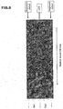
- Fig.10 illustrates an example of a portion of the output produced by a scanning device performing measurements on the overall calibration pattern represented in Fig.9D .
- the scanning device has comparable sensitivity to the scanning device whose output is illustrated in Fig.3 .
- the scanning device detects the extent and pattern of variation in printed image intensity across the page considerably more accurately in the case of Fig.10 than in the case of Fig.3 .
- the enlargement of the calibration pattern portions printed by groups of nozzles in methods according to examples of the invention enables the same scanning device to achieve improved accuracy in detecting print defects associated with those nozzles.
- the number of nozzles at the ends of a print die which are susceptible to print at a lighter intensity than the nozzles towards the centre of the print die is not always the same.
- the affected number of nozzles at the ends of the print dies can be determined as part of a product-characterization process during the manufacture of the nozzle array, the printing assembly or the overall printer itself, and this number may be stored in memory for use during the calibration-pattern printing process. Alternatively this number may be used to generate driving data for the calibration-pattern printing process and the driving data may be stored.
- the calibration-pattern printing process of Figs.8 and 9 can then be implemented to include the predetermined number of nozzles in the first nozzle-array portions.
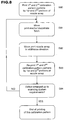
- Fig.11 illustrates a calibration method according to an example of the invention.
- step S200 of the calibration method according to the example of Fig.11 a printed calibration pattern including at least one enlarged calibration pattern portion produced, in this example, by the calibration-pattern printing method according to Figs.8 and 9 , is scanned by a scanning device provided in the printer, such as element 12 of Fig.1 .
- the scanning device includes a sensor element (e.g. a densitometer) that detects the density of ink in the printed image as the sensing element is moved across the calibration pattern in the widthwise direction.
- a sensor element e.g. a densitometer
- the output from the scanning device is supplied to a processing element, such as control unit 10 in Fig.1 , which is configured to analyze the calibration pattern based on the output from the scanning device (step S201 of Fig.11 ).
- the control unit 10 is programmed to measure the difference between the measured density at regions corresponding to enlarged calibration pattern portions E printed by the first nozzle-array portions and at regions corresponding to the enlarged reference calibration pattern portions M printed by the second nozzle-array portions.
- This difference represents the degree by which the nozzles at the ends of the print dies are printing lighter than the nozzles towards the centres of the print dies.
- the drive signals for activating the print nozzles at the ends of the print dies can be modified based on the measured difference, notably to drive those nozzles with a greater-than-standard signal in order to compensate for the fact that these nozzles print lighter-than-expected.
- the control unit can inform the print controller of the manner in which the drive signals to the print nozzles of the first nozzle-array portion should be adjusted for future printing operations.
- the print controller notes this information, for example by writing into a memory some data defining a function to be used when converting print data to drive signals for the nozzles in question during subsequent printing operations.
- the invention is not limited to that approach.
- the control unit 10 makes use of measurement data relating to an enlarged calibration pattern portion (e.g. ENL E1 in Fig.9C ) to determine how the drive signals to a relatively narrower nozzle-array portion should be modified.
- the control unit makes use of scanner output relating to a region of width W in a calibration pattern, this region W having a greater width than w and corresponding to an enlarged calibration pattern portion printed by repeated operation of the nozzle-array portion NG.
- the control unit 10 is programmed to know the correspondence between each of the regions spanned by the enlarged calibration pattern portions in the printed image and the print nozzles that printed those enlarged calibration pattern portions.
- Calibration processes may be implemented from time to time during the lifetime of a printer, to keep the calibration of the printer accurate despite varying conditions, for example as environmental conditions change, as the printer components age, when components in the printer are replaced, as operating conditions (print speed, print medium, etc.) change, and so on.
- the calibration may compensate for dynamic factors and, thus, produce a more accurate compensation of errors.
- the relative position between a print medium and a print nozzle array in the longitudinal direction is varied by moving the substrate back and forth as required along a printing path.
- the relative motion could be obtained by holding the substrate still and moving the array of print nozzles back and forth in the longitudinal direction, or by a combination of movement of the substrate and the nozzle array.
- the examples described above refer to monochrome printing using print nozzles on a single printbar.
- the invention is applicable in general to the printing of calibration patterns in monochrome and color printers.
- the above description refers to the use of scanning devices for measuring the print characteristics of images, notably of calibration patterns.
- the invention is not limited to the use of measurement devices which scan across a printed image, other kinds of detection and/or measurement devices may be used.
- the above description refers to printers in which the printing elements include a printbar and print dies bearing print nozzles.
- the invention is not particularly limited having regard to the configuration of the array of print nozzles in the printing element.
Landscapes
- Engineering & Computer Science (AREA)
- Quality & Reliability (AREA)
- Ink Jet (AREA)
Claims (15)
- Procédé d'impression d'un motif d'étalonnage dans une imprimante matricielle ayant la largeur d'une page qui comporte une matrice de buses d'impression qui s'étend dans une direction transversale de l'imprimante, le procédé comprenant les étapes consistant :à imprimer une partie de motif d'étalonnage respective sur un substrat au moyen d'au moins une première partie de la matrice de buses ;à modifier la position relative de la matrice de buses et du substrat dans la direction transversale, puis imprimer une autre partie de motif d'étalonnage respective sur le substrat au moyen de ladite au moins une première partie de la matrice de buses de telle sorte qu'une première partie donnée de la matrice de buses imprime une partie de motif d'étalonnage et une autre partie de motif d'étalonnage qui sont au moins partiellement alignées l'une avec l'autre dans la direction longitudinale et se rejoignent dans la direction transversale pour former une partie de motif d'étalonnage agrandie.
- Procédé d'impression de motif d'étalonnage selon la revendication 1, dans lequel l'étendue transversale de la partie de motif d'étalonnage agrandie est réglée en fonction de la résolution d'un capteur situé dans l'imprimante matricielle ayant la largeur d'une page.
- Procédé d'impression de motif d'étalonnage selon la revendication 2, comprenant l'étape consistant à répéter l'étape de modification de sorte qu'une première partie donnée de la matrice de buses imprime des parties de motif d'étalonnage supplémentaires qui se joignent à la partie de motif d'étalonnage et l'autre partie de motif d'étalonnage dans la direction transversale pour former une partie de motif d'étalonnage agrandie dont l'étendue transversale est au moins aussi grande que la dimension caractéristique minimale définie par la résolution du capteur.
- Procédé d'impression de motif d'étalonnage selon la revendication 2, dans lequel la position relative de la matrice de buses et du substrat dans la direction transversale est modifiée par déplacement de la matrice de buses dans la direction transversale.
- Procédé d'impression de motif d'étalonnage selon la revendication 4 dans une imprimante matricielle ayant la largeur d'une page, dans laquelle la matrice de buses d'impression est placée sur un ensemble de blocs d'impression, une première partie respective de la matrice de buses comprenant un nombre prédéterminé de buses à l'extrémité d'un bloc d'impression, ledit procédé comprenant les étapes consistant :à imprimer une partie de motif d'étalonnage de référence respective sur le substrat au moyen d'au moins une seconde partie de la matrice de buses ne comprenant pas de buses qui se trouvent à l'extrémité d'un bloc d'impression ; età modifier la position relative de la matrice de buses et du substrat dans la direction transversale, puis à imprimer une autre portion de motif d'étalonnage de référence respective sur le substrat au moyen de ladite au moins une seconde partie de la matrice de buses de telle sorte qu'une seconde partie donnée de la matrice de buses imprime une partie de motif d'étalonnage de référence et une autre partie de motif d'étalonnage de référence qui sont au moins partiellement alignées l'une avec l'autre dans la direction longitudinale et se joignent dans la direction transversale pour former une partie de motif d'étalonnage de référence agrandie.
- Procédé d'impression de motif d'étalonnage selon la revendication 5, dans lequel ladite première partie et ladite seconde partie de la matrice de buses impriment la partie de motif d'étalonnage et la partie de motif d'étalonnage de référence dans une première opération d'impression commune et impriment l'autre partie de motif d'étalonnage et l'autre partie de motif d'étalonnage de référence dans une seconde opération d'impression commune.
- Procédé d'étalonnage d'une imprimante matricielle ayant la largeur d'une page, le procédé comprenant le procédé d'impression de motif d'étalonnage selon la revendication 6, et comprenant en outre les étapes consistant :à mesurer une différence entre une partie de motif d'étalonnage agrandie imprimée par une première partie de la matrice de buses et une partie de motif d'étalonnage de référence agrandie imprimée par une seconde partie de la matrice de buses ; età régler les signaux de commande destinés à au moins une parmi la première partie de la matrice de buses et la seconde partie de la matrice de buses pour compenser la différence mesurée à l'étape de mesure.
- Procédé d'étalonnage selon la revendication 7, dans lequel l'étape de réglage comprend le réglage de signaux de commande de buses étalés sur une distance dans la direction transversale qui est inférieure à l'étendue transversale de la partie de motif d'étalonnage agrandie.
- Procédé d'impression d'un motif d'étalonnage dans une imprimante matricielle ayant la largeur d'une page, comprenant une barre d'impression pourvue d'une matrice de buses d'impression qui s'étend dans le sens de la largeur de l'imprimante, le procédé comprenant les étapes consistant :à imprimer une première partie de motif d'étalonnage respective sur un substrat au moyen d'au moins une première partie de la matrice de buses à mesure que le substrat avance à travers l'imprimante ;à déplacer le substrat en arrière à travers l'imprimante dans la direction opposée à la direction d'avancement ;à modifier la position de la barre d'impression dans le sens de la largeur ; età imprimer une seconde partie de motif d'étalonnage respective sur le substrat au moyen de ladite au moins une première partie de la matrice de buses avec la barre d'impression dans la position modifiée, les première et seconde parties de motif d'étalonnage imprimées sur le substrat par une première partie donnée de la matrice de buse étant contiguës et formant sur le substrat une partie de motif d'étalonnage agrandie dans le sens de la largeur.
- Procédé d'impression de motif d'étalonnage selon la revendication 9, dans lequel la largeur de la partie de motif d'étalonnage agrandie dans le sens de la largeur est réglée en fonction de la résolution d'un capteur dans l'imprimante.
- Procédé d'impression de motif d'étalonnage selon la revendication 10 dans une imprimante matricielle ayant la largeur d'une page, dans laquelle la matrice de buses d'impression est disposée sur un ensemble de blocs d'impression, une première partie respective de la matrice de buses comprenant un nombre prédéterminé de buses à l'extrémité d'un bloc d'impression, le procédé comprenant les étapes consistant :à imprimer une première partie de motif d'étalonnage de référence respective sur le substrat au moyen d'au moins une seconde partie de la matrice de buses, ne comprenant pas de buses à l'extrémité des blocs d'impression, à mesure que le substrat avance à travers l'imprimante ; età imprimer une seconde partie de motif d'étalonnage de référence respective sur le substrat au moyen de ladite au moins une seconde partie de la matrice de buses avec la barre d'impression dans la position modifiée, les première et seconde parties de motif d'étalonnage de référence imprimées sur le substrat par une seconde partie donnée de la matrice de buses étant contiguës et formant une partie de motif d'étalonnage de référence agrandie dans le sens de la largeur.
- Procédé d'impression de motif d'étalonnage selon la revendication 11, le procédé comprenant en outre les étapes consistant :à mesurer une différence entre la partie de motif d'étalonnage agrandie dans le sens de la largeur imprimée par une première partie de la matrice de buses et une partie de motif d'étalonnage de référence agrandie dans le sens de la largeur imprimée par une seconde partie de la matrice de buses ; età régler les signaux de commande destinés à au moins une parmi la première partie de la matrice de buses et la seconde partie de la matrice de buses pour compenser la différence mesurée à l'étape de mesure.
- Imprimante matricielle ayant la largeur d'une page comprenant :une barre d'impression comportant une matrice de buses d'impression s'étendant dans le sens de la largeur ;un dispositif de commande de position de barre d'impression destiné à commander la position de la barre d'impression dans le sens de la largeur ;un dispositif de commande d'impression destiné à commander l'activation des buses d'impression de la matrice ; etune unité de commande destinée à commander le dispositif de commande d'impression pour activer au moins une première partie de la matrice de buses pour imprimer une partie de motif d'étalonnage respective et une autre partie de motif d'étalonnage sur un substrat, et pour commander le dispositif de commande de position de barre d'impression pour modifier la position relative de la matrice de buses et du substrat dans la direction transversale entre l'impression de la partie de motif d'étalonnage respective et l'impression de l'autre partie de motif d'étalonnage, pour qu'une première partie donnée de la matrice de buses imprime une partie de motif d'étalonnage et une autre partie de motif d'étalonnage qui sont au moins partiellement alignées dans la direction longitudinale et se joignent dans la direction transversale pour former une partie de motif d'étalonnage agrandie.
- Imprimante matricielle ayant la largeur d'une page selon la revendication 13, dans laquelle la matrice de buses d'impression est disposée sur un ensemble de blocs d'impression et la ou chaque première portion respective de la matrice de buses comprend un nombre prédéterminé de buses à l'extrémité d'un bloc d'impression.
- Imprimante matricielle ayant la largeur d'une page selon la revendication 14, l'imprimante comprenant en outre un capteur destiné à mesurer au moins une caractéristique de la partie de motif d'étalonnage agrandie imprimée sur le substrat et à délivrer un signal de commande au dispositif de commande d'impression pour régler les signaux de commande par rapport aux buses de la matrice de buses couvrant une largeur inférieure à la largeur de la partie de motif d'étalonnage agrandie.
Applications Claiming Priority (1)
| Application Number | Priority Date | Filing Date | Title |
|---|---|---|---|
| PCT/EP2013/051557 WO2014114355A1 (fr) | 2013-01-28 | 2013-01-28 | Procédés d'impression de motifs de calibrage, procédés de calibrage, et imprimantes |
Publications (2)
| Publication Number | Publication Date |
|---|---|
| EP2938497A1 EP2938497A1 (fr) | 2015-11-04 |
| EP2938497B1 true EP2938497B1 (fr) | 2016-04-06 |
Family
ID=47678731
Family Applications (1)
| Application Number | Title | Priority Date | Filing Date |
|---|---|---|---|
| EP13702960.9A Active EP2938497B1 (fr) | 2013-01-28 | 2013-01-28 | Procédé pour imprimer des impressions de calibrage, procédés de calibrage et des imprimants |
Country Status (4)
| Country | Link |
|---|---|
| US (2) | US9296238B2 (fr) |
| EP (1) | EP2938497B1 (fr) |
| CN (1) | CN105050818B (fr) |
| WO (1) | WO2014114355A1 (fr) |
Families Citing this family (15)
| Publication number | Priority date | Publication date | Assignee | Title |
|---|---|---|---|---|
| WO2016133507A1 (fr) * | 2015-02-18 | 2016-08-25 | Hewlett-Packard Development Company, L.P. | Estimation de l'espacement stylo-papier |
| JP6656371B2 (ja) * | 2015-11-19 | 2020-03-04 | ヒューレット−パッカード デベロップメント カンパニー エル.ピー.Hewlett‐Packard Development Company, L.P. | インデックス式スキャンバーを用いるダイアライメント |
| US10589554B2 (en) * | 2016-03-17 | 2020-03-17 | Hewlett-Packard Development Company, L.P. | Printer to determine calibration pattern |
| EP3510758A4 (fr) * | 2016-09-09 | 2020-04-08 | Hewlett-Packard Development Company, L.P. | Étalonnage de barre de balayage |
| JP6997526B2 (ja) * | 2017-03-30 | 2022-01-17 | 株式会社Screenホールディングス | インクジェット印刷装置の補正値取得方法及びインクジェット印刷装置 |
| JP6895857B2 (ja) * | 2017-09-25 | 2021-06-30 | 株式会社Screenホールディングス | インクジェット印刷装置および濃淡補正方法 |
| US11135834B1 (en) | 2017-11-13 | 2021-10-05 | Hewlett-Packard Development Company, L.P. | Interferential patterns for printer calibration |
| CN110722893A (zh) * | 2018-07-16 | 2020-01-24 | 星云电脑股份有限公司 | 一种可使堆栈打印边缘具圆滑效果的uv喷墨打印方法 |
| JP7172493B2 (ja) * | 2018-11-19 | 2022-11-16 | コニカミノルタ株式会社 | 画像形成装置、画像形成装置のシェーディング補正方法およびシェーディング補正プログラム |
| WO2020110827A1 (fr) * | 2018-11-29 | 2020-06-04 | 京セラ株式会社 | Appareil d'enregistrement et programme pour appareil d'enregistrement |
| EP3666523A1 (fr) * | 2018-12-11 | 2020-06-17 | Concept Laser GmbH | Procédé d'étalonnage d'un dispositif d'irradiation pour un appareil de fabrication additive d'objets tridimensionnels |
| KR102703963B1 (ko) | 2019-10-03 | 2024-09-05 | 휴렛-팩커드 디벨롭먼트 컴퍼니, 엘.피. | 인쇄 디바이스의 교정 |
| JP7647265B2 (ja) * | 2021-04-08 | 2025-03-18 | 株式会社リコー | 液体吐出装置、液体吐出方法、及び、プログラム |
| IT202100015875A1 (it) * | 2021-06-17 | 2022-12-17 | Antonio Maccari | Metodo per valutare il risultato di stampa di un dispositivo di stampa a getto d'inchiostro e mezzi di supporto stampati aventi un elemento di calibrazione. |
| CN116238248A (zh) * | 2023-03-29 | 2023-06-09 | 苏州市森泓技术有限公司 | 一种打印机喷头位置的校准方法及校准系统 |
Family Cites Families (20)
| Publication number | Priority date | Publication date | Assignee | Title |
|---|---|---|---|---|
| JP3040433B2 (ja) * | 1990-06-11 | 2000-05-15 | キヤノン株式会社 | 補正データ作成方法 |
| US6076915A (en) | 1998-08-03 | 2000-06-20 | Hewlett-Packard Company | Inkjet printhead calibration |
| CN1144679C (zh) | 1999-04-22 | 2004-04-07 | 佳能精技股份有限公司 | 图象形成装置和用于检测打印位置偏差的方法 |
| US6940618B2 (en) * | 2000-11-29 | 2005-09-06 | Hewlett-Packard Development Company, L.P. | Linefeed calibration method for a printer |
| JP4715209B2 (ja) * | 2004-09-01 | 2011-07-06 | コニカミノルタホールディングス株式会社 | インクジェット記録装置 |
| GB0426126D0 (en) | 2004-11-29 | 2004-12-29 | Plastic Logic Ltd | Distortion compensation for multiple head printing |
| TWI250084B (en) | 2004-12-08 | 2006-03-01 | Ind Tech Res Inst | Method of calibrating inkjet print head |
| KR100788665B1 (ko) * | 2005-06-01 | 2007-12-26 | 삼성전자주식회사 | 잉크젯 프린터의 미싱노즐 검출방법 |
| EP1764996A1 (fr) * | 2005-09-20 | 2007-03-21 | Agfa Graphics N.V. | Procédé et appareil pour l'alignement automatique de matrices d'éléments d'impression |
| US8496315B2 (en) * | 2006-06-26 | 2013-07-30 | Canon Finetech Inc. | Registration adjustment value determination method, recording system, and registration adjustment method |
| JP5117423B2 (ja) * | 2009-02-19 | 2013-01-16 | 富士フイルム株式会社 | 画像記録装置、画像処理装置、画像処理方法及びプログラム |
| JP5398300B2 (ja) * | 2009-02-27 | 2014-01-29 | 富士フイルム株式会社 | 画像記録装置、画像処理装置、画像処理方法及びプログラム |
| US8136913B2 (en) * | 2009-03-20 | 2012-03-20 | Xerox Corporation | System and method for measuring drop position in an image of a test pattern on an image substrate |
| JP5473435B2 (ja) * | 2009-06-30 | 2014-04-16 | キヤノン株式会社 | 記録装置の制御方法 |
| US8427698B2 (en) * | 2009-08-19 | 2013-04-23 | Eastman Kodak Company | Enhanced imaging with adjusted image swath widths |
| JP2011073286A (ja) * | 2009-09-30 | 2011-04-14 | Fujifilm Corp | 画像記録装置及び画像記録方法 |
| US8251484B2 (en) | 2010-05-14 | 2012-08-28 | Xerox Corporation | Method and system for measuring and compensating for sensitivity and backlash in electrical motors that laterally move printheads in a continuous web inkjet printer |
| JP5822454B2 (ja) * | 2010-11-10 | 2015-11-24 | キヤノン株式会社 | 画像処理装置および画像処理方法 |
| JP5442783B2 (ja) * | 2012-02-02 | 2014-03-12 | 富士フイルム株式会社 | 画像記録装置、画像処理装置、画像記録方法及び画像処理方法並びにプログラム |
| KR102293444B1 (ko) * | 2015-02-13 | 2021-08-25 | 휴렛-팩커드 디벨롭먼트 컴퍼니, 엘.피. | 프린터 및 프린터를 제어하기 위한 컴퓨터 구현형 프로세서 |
-
2013
- 2013-01-28 US US14/762,794 patent/US9296238B2/en active Active
- 2013-01-28 WO PCT/EP2013/051557 patent/WO2014114355A1/fr not_active Ceased
- 2013-01-28 CN CN201380075104.2A patent/CN105050818B/zh active Active
- 2013-01-28 EP EP13702960.9A patent/EP2938497B1/fr active Active
-
2016
- 2016-03-14 US US15/069,119 patent/US10583650B2/en active Active
Also Published As
| Publication number | Publication date |
|---|---|
| WO2014114355A1 (fr) | 2014-07-31 |
| CN105050818A (zh) | 2015-11-11 |
| US20160214376A1 (en) | 2016-07-28 |
| US9296238B2 (en) | 2016-03-29 |
| US10583650B2 (en) | 2020-03-10 |
| US20150367662A1 (en) | 2015-12-24 |
| CN105050818B (zh) | 2016-10-12 |
| EP2938497A1 (fr) | 2015-11-04 |
Similar Documents
| Publication | Publication Date | Title |
|---|---|---|
| EP2938497B1 (fr) | Procédé pour imprimer des impressions de calibrage, procédés de calibrage et des imprimants | |
| US8733877B2 (en) | Method and apparatus for detecting discharge defect, image processing apparatus, computer-readable recording medium, and printing system | |
| US9340009B2 (en) | Printing apparatus and processing method therefor | |
| US7484821B2 (en) | Method of determining ink ejection method, printing apparatus, and method of manufacturing printing apparatus | |
| CN108349273B (zh) | 校准页宽阵列打印装置的介质推进系统 | |
| US8292393B2 (en) | Recording apparatus and transport method | |
| JP6106395B2 (ja) | 画像形成装置 | |
| US7758139B2 (en) | Liquid ejecting apparatus and transport method | |
| US20150165760A1 (en) | Apparatus and method for recording | |
| JP2014104679A (ja) | インクジェット記録装置およびインクジェット記録装置の制御方法 | |
| US7931347B2 (en) | Transporting method and recording apparatus | |
| JP5915166B2 (ja) | 印刷装置、及び、補正方法 | |
| US8029085B2 (en) | Recording method | |
| JP2019069625A (ja) | 印刷装置 | |
| CN101037056A (zh) | 打印系统及其校正喷墨位置的方法 | |
| US12115799B2 (en) | Printing apparatus and printing method | |
| US20250196509A1 (en) | Printing apparatus and control method | |
| JP7718198B2 (ja) | 記録装置および記録方法 | |
| JP2008093851A (ja) | 補正値の設定方法、補正値設定システム、及び、プログラム | |
| CN1676333A (zh) | 打印系统及其校正喷墨位置的方法 |
Legal Events
| Date | Code | Title | Description |
|---|---|---|---|
| PUAI | Public reference made under article 153(3) epc to a published international application that has entered the european phase |
Free format text: ORIGINAL CODE: 0009012 |
|
| REG | Reference to a national code |
Ref country code: DE Ref legal event code: R079 Ref document number: 602013006211 Country of ref document: DE Free format text: PREVIOUS MAIN CLASS: B41J0002210000 Ipc: B41J0029393000 |
|
| 17P | Request for examination filed |
Effective date: 20150724 |
|
| AK | Designated contracting states |
Kind code of ref document: A1 Designated state(s): AL AT BE BG CH CY CZ DE DK EE ES FI FR GB GR HR HU IE IS IT LI LT LU LV MC MK MT NL NO PL PT RO RS SE SI SK SM TR |
|
| AX | Request for extension of the european patent |
Extension state: BA ME |
|
| GRAP | Despatch of communication of intention to grant a patent |
Free format text: ORIGINAL CODE: EPIDOSNIGR1 |
|
| RIC1 | Information provided on ipc code assigned before grant |
Ipc: B41J 29/393 20060101AFI20151022BHEP Ipc: B41J 2/21 20060101ALI20151022BHEP |
|
| INTG | Intention to grant announced |
Effective date: 20151116 |
|
| GRAS | Grant fee paid |
Free format text: ORIGINAL CODE: EPIDOSNIGR3 |
|
| GRAA | (expected) grant |
Free format text: ORIGINAL CODE: 0009210 |
|
| DAX | Request for extension of the european patent (deleted) | ||
| AK | Designated contracting states |
Kind code of ref document: B1 Designated state(s): AL AT BE BG CH CY CZ DE DK EE ES FI FR GB GR HR HU IE IS IT LI LT LU LV MC MK MT NL NO PL PT RO RS SE SI SK SM TR |
|
| REG | Reference to a national code |
Ref country code: GB Ref legal event code: FG4D |
|
| REG | Reference to a national code |
Ref country code: AT Ref legal event code: REF Ref document number: 787305 Country of ref document: AT Kind code of ref document: T Effective date: 20160415 Ref country code: CH Ref legal event code: EP |
|
| REG | Reference to a national code |
Ref country code: IE Ref legal event code: FG4D |
|
| REG | Reference to a national code |
Ref country code: DE Ref legal event code: R096 Ref document number: 602013006211 Country of ref document: DE |
|
| REG | Reference to a national code |
Ref country code: LT Ref legal event code: MG4D Ref country code: NL Ref legal event code: MP Effective date: 20160406 |
|
| REG | Reference to a national code |
Ref country code: AT Ref legal event code: MK05 Ref document number: 787305 Country of ref document: AT Kind code of ref document: T Effective date: 20160406 |
|
| PG25 | Lapsed in a contracting state [announced via postgrant information from national office to epo] |
Ref country code: NL Free format text: LAPSE BECAUSE OF FAILURE TO SUBMIT A TRANSLATION OF THE DESCRIPTION OR TO PAY THE FEE WITHIN THE PRESCRIBED TIME-LIMIT Effective date: 20160406 |
|
| PG25 | Lapsed in a contracting state [announced via postgrant information from national office to epo] |
Ref country code: LT Free format text: LAPSE BECAUSE OF FAILURE TO SUBMIT A TRANSLATION OF THE DESCRIPTION OR TO PAY THE FEE WITHIN THE PRESCRIBED TIME-LIMIT Effective date: 20160406 Ref country code: PL Free format text: LAPSE BECAUSE OF FAILURE TO SUBMIT A TRANSLATION OF THE DESCRIPTION OR TO PAY THE FEE WITHIN THE PRESCRIBED TIME-LIMIT Effective date: 20160406 Ref country code: FI Free format text: LAPSE BECAUSE OF FAILURE TO SUBMIT A TRANSLATION OF THE DESCRIPTION OR TO PAY THE FEE WITHIN THE PRESCRIBED TIME-LIMIT Effective date: 20160406 Ref country code: NO Free format text: LAPSE BECAUSE OF FAILURE TO SUBMIT A TRANSLATION OF THE DESCRIPTION OR TO PAY THE FEE WITHIN THE PRESCRIBED TIME-LIMIT Effective date: 20160706 Ref country code: IS Free format text: LAPSE BECAUSE OF FAILURE TO SUBMIT A TRANSLATION OF THE DESCRIPTION OR TO PAY THE FEE WITHIN THE PRESCRIBED TIME-LIMIT Effective date: 20160806 |
|
| PG25 | Lapsed in a contracting state [announced via postgrant information from national office to epo] |
Ref country code: RS Free format text: LAPSE BECAUSE OF FAILURE TO SUBMIT A TRANSLATION OF THE DESCRIPTION OR TO PAY THE FEE WITHIN THE PRESCRIBED TIME-LIMIT Effective date: 20160406 Ref country code: LV Free format text: LAPSE BECAUSE OF FAILURE TO SUBMIT A TRANSLATION OF THE DESCRIPTION OR TO PAY THE FEE WITHIN THE PRESCRIBED TIME-LIMIT Effective date: 20160406 Ref country code: SE Free format text: LAPSE BECAUSE OF FAILURE TO SUBMIT A TRANSLATION OF THE DESCRIPTION OR TO PAY THE FEE WITHIN THE PRESCRIBED TIME-LIMIT Effective date: 20160406 Ref country code: ES Free format text: LAPSE BECAUSE OF FAILURE TO SUBMIT A TRANSLATION OF THE DESCRIPTION OR TO PAY THE FEE WITHIN THE PRESCRIBED TIME-LIMIT Effective date: 20160406 Ref country code: PT Free format text: LAPSE BECAUSE OF FAILURE TO SUBMIT A TRANSLATION OF THE DESCRIPTION OR TO PAY THE FEE WITHIN THE PRESCRIBED TIME-LIMIT Effective date: 20160808 Ref country code: AT Free format text: LAPSE BECAUSE OF FAILURE TO SUBMIT A TRANSLATION OF THE DESCRIPTION OR TO PAY THE FEE WITHIN THE PRESCRIBED TIME-LIMIT Effective date: 20160406 Ref country code: HR Free format text: LAPSE BECAUSE OF FAILURE TO SUBMIT A TRANSLATION OF THE DESCRIPTION OR TO PAY THE FEE WITHIN THE PRESCRIBED TIME-LIMIT Effective date: 20160406 Ref country code: GR Free format text: LAPSE BECAUSE OF FAILURE TO SUBMIT A TRANSLATION OF THE DESCRIPTION OR TO PAY THE FEE WITHIN THE PRESCRIBED TIME-LIMIT Effective date: 20160707 |
|
| REG | Reference to a national code |
Ref country code: FR Ref legal event code: PLFP Year of fee payment: 5 |
|
| PG25 | Lapsed in a contracting state [announced via postgrant information from national office to epo] |
Ref country code: IT Free format text: LAPSE BECAUSE OF FAILURE TO SUBMIT A TRANSLATION OF THE DESCRIPTION OR TO PAY THE FEE WITHIN THE PRESCRIBED TIME-LIMIT Effective date: 20160406 Ref country code: BE Free format text: LAPSE BECAUSE OF FAILURE TO SUBMIT A TRANSLATION OF THE DESCRIPTION OR TO PAY THE FEE WITHIN THE PRESCRIBED TIME-LIMIT Effective date: 20160406 |
|
| REG | Reference to a national code |
Ref country code: DE Ref legal event code: R097 Ref document number: 602013006211 Country of ref document: DE |
|
| PG25 | Lapsed in a contracting state [announced via postgrant information from national office to epo] |
Ref country code: EE Free format text: LAPSE BECAUSE OF FAILURE TO SUBMIT A TRANSLATION OF THE DESCRIPTION OR TO PAY THE FEE WITHIN THE PRESCRIBED TIME-LIMIT Effective date: 20160406 Ref country code: CZ Free format text: LAPSE BECAUSE OF FAILURE TO SUBMIT A TRANSLATION OF THE DESCRIPTION OR TO PAY THE FEE WITHIN THE PRESCRIBED TIME-LIMIT Effective date: 20160406 Ref country code: DK Free format text: LAPSE BECAUSE OF FAILURE TO SUBMIT A TRANSLATION OF THE DESCRIPTION OR TO PAY THE FEE WITHIN THE PRESCRIBED TIME-LIMIT Effective date: 20160406 Ref country code: SK Free format text: LAPSE BECAUSE OF FAILURE TO SUBMIT A TRANSLATION OF THE DESCRIPTION OR TO PAY THE FEE WITHIN THE PRESCRIBED TIME-LIMIT Effective date: 20160406 Ref country code: RO Free format text: LAPSE BECAUSE OF FAILURE TO SUBMIT A TRANSLATION OF THE DESCRIPTION OR TO PAY THE FEE WITHIN THE PRESCRIBED TIME-LIMIT Effective date: 20160406 |
|
| PLBE | No opposition filed within time limit |
Free format text: ORIGINAL CODE: 0009261 |
|
| STAA | Information on the status of an ep patent application or granted ep patent |
Free format text: STATUS: NO OPPOSITION FILED WITHIN TIME LIMIT |
|
| PG25 | Lapsed in a contracting state [announced via postgrant information from national office to epo] |
Ref country code: SM Free format text: LAPSE BECAUSE OF FAILURE TO SUBMIT A TRANSLATION OF THE DESCRIPTION OR TO PAY THE FEE WITHIN THE PRESCRIBED TIME-LIMIT Effective date: 20160406 |
|
| 26N | No opposition filed |
Effective date: 20170110 |
|
| PG25 | Lapsed in a contracting state [announced via postgrant information from national office to epo] |
Ref country code: SI Free format text: LAPSE BECAUSE OF FAILURE TO SUBMIT A TRANSLATION OF THE DESCRIPTION OR TO PAY THE FEE WITHIN THE PRESCRIBED TIME-LIMIT Effective date: 20160406 |
|
| REG | Reference to a national code |
Ref country code: CH Ref legal event code: PL |
|
| PG25 | Lapsed in a contracting state [announced via postgrant information from national office to epo] |
Ref country code: MC Free format text: LAPSE BECAUSE OF FAILURE TO SUBMIT A TRANSLATION OF THE DESCRIPTION OR TO PAY THE FEE WITHIN THE PRESCRIBED TIME-LIMIT Effective date: 20160406 |
|
| PG25 | Lapsed in a contracting state [announced via postgrant information from national office to epo] |
Ref country code: CH Free format text: LAPSE BECAUSE OF NON-PAYMENT OF DUE FEES Effective date: 20170131 Ref country code: LI Free format text: LAPSE BECAUSE OF NON-PAYMENT OF DUE FEES Effective date: 20170131 |
|
| REG | Reference to a national code |
Ref country code: IE Ref legal event code: MM4A |
|
| REG | Reference to a national code |
Ref country code: FR Ref legal event code: PLFP Year of fee payment: 6 |
|
| PG25 | Lapsed in a contracting state [announced via postgrant information from national office to epo] |
Ref country code: LU Free format text: LAPSE BECAUSE OF NON-PAYMENT OF DUE FEES Effective date: 20170128 |
|
| PG25 | Lapsed in a contracting state [announced via postgrant information from national office to epo] |
Ref country code: IE Free format text: LAPSE BECAUSE OF NON-PAYMENT OF DUE FEES Effective date: 20170128 |
|
| PG25 | Lapsed in a contracting state [announced via postgrant information from national office to epo] |
Ref country code: MT Free format text: LAPSE BECAUSE OF NON-PAYMENT OF DUE FEES Effective date: 20170128 |
|
| PG25 | Lapsed in a contracting state [announced via postgrant information from national office to epo] |
Ref country code: AL Free format text: LAPSE BECAUSE OF FAILURE TO SUBMIT A TRANSLATION OF THE DESCRIPTION OR TO PAY THE FEE WITHIN THE PRESCRIBED TIME-LIMIT Effective date: 20160406 |
|
| PG25 | Lapsed in a contracting state [announced via postgrant information from national office to epo] |
Ref country code: HU Free format text: LAPSE BECAUSE OF FAILURE TO SUBMIT A TRANSLATION OF THE DESCRIPTION OR TO PAY THE FEE WITHIN THE PRESCRIBED TIME-LIMIT; INVALID AB INITIO Effective date: 20130128 |
|
| PG25 | Lapsed in a contracting state [announced via postgrant information from national office to epo] |
Ref country code: BG Free format text: LAPSE BECAUSE OF FAILURE TO SUBMIT A TRANSLATION OF THE DESCRIPTION OR TO PAY THE FEE WITHIN THE PRESCRIBED TIME-LIMIT Effective date: 20160406 |
|
| PG25 | Lapsed in a contracting state [announced via postgrant information from national office to epo] |
Ref country code: CY Free format text: LAPSE BECAUSE OF FAILURE TO SUBMIT A TRANSLATION OF THE DESCRIPTION OR TO PAY THE FEE WITHIN THE PRESCRIBED TIME-LIMIT Effective date: 20160406 |
|
| PG25 | Lapsed in a contracting state [announced via postgrant information from national office to epo] |
Ref country code: MK Free format text: LAPSE BECAUSE OF FAILURE TO SUBMIT A TRANSLATION OF THE DESCRIPTION OR TO PAY THE FEE WITHIN THE PRESCRIBED TIME-LIMIT Effective date: 20160406 |
|
| PG25 | Lapsed in a contracting state [announced via postgrant information from national office to epo] |
Ref country code: TR Free format text: LAPSE BECAUSE OF FAILURE TO SUBMIT A TRANSLATION OF THE DESCRIPTION OR TO PAY THE FEE WITHIN THE PRESCRIBED TIME-LIMIT Effective date: 20160406 |
|
| PGFP | Annual fee paid to national office [announced via postgrant information from national office to epo] |
Ref country code: GB Payment date: 20211216 Year of fee payment: 10 Ref country code: FR Payment date: 20211215 Year of fee payment: 10 |
|
| GBPC | Gb: european patent ceased through non-payment of renewal fee |
Effective date: 20230128 |
|
| PG25 | Lapsed in a contracting state [announced via postgrant information from national office to epo] |
Ref country code: GB Free format text: LAPSE BECAUSE OF NON-PAYMENT OF DUE FEES Effective date: 20230128 |
|
| PG25 | Lapsed in a contracting state [announced via postgrant information from national office to epo] |
Ref country code: FR Free format text: LAPSE BECAUSE OF NON-PAYMENT OF DUE FEES Effective date: 20230131 |
|
| PGFP | Annual fee paid to national office [announced via postgrant information from national office to epo] |
Ref country code: DE Payment date: 20241218 Year of fee payment: 13 |