EP2938574B1 - Procédé de retrait d'hydrocarbures d'un plan d'eau par perméation sélective et appareil associé - Google Patents
Procédé de retrait d'hydrocarbures d'un plan d'eau par perméation sélective et appareil associé Download PDFInfo
- Publication number
- EP2938574B1 EP2938574B1 EP13828878.2A EP13828878A EP2938574B1 EP 2938574 B1 EP2938574 B1 EP 2938574B1 EP 13828878 A EP13828878 A EP 13828878A EP 2938574 B1 EP2938574 B1 EP 2938574B1
- Authority
- EP
- European Patent Office
- Prior art keywords
- filter
- hydrocarbons
- water
- process according
- hollow structure
- Prior art date
- Legal status (The legal status is an assumption and is not a legal conclusion. Google has not performed a legal analysis and makes no representation as to the accuracy of the status listed.)
- Active
Links
Images

Classifications
-
- C—CHEMISTRY; METALLURGY
- C02—TREATMENT OF WATER, WASTE WATER, SEWAGE, OR SLUDGE
- C02F—TREATMENT OF WATER, WASTE WATER, SEWAGE, OR SLUDGE
- C02F1/00—Treatment of water, waste water, or sewage
- C02F1/40—Devices for separating or removing fatty or oily substances or similar floating material
-
- C—CHEMISTRY; METALLURGY
- C02—TREATMENT OF WATER, WASTE WATER, SEWAGE, OR SLUDGE
- C02F—TREATMENT OF WATER, WASTE WATER, SEWAGE, OR SLUDGE
- C02F1/00—Treatment of water, waste water, or sewage
- C02F1/28—Treatment of water, waste water, or sewage by sorption
- C02F1/288—Treatment of water, waste water, or sewage by sorption using composite sorbents, e.g. coated, impregnated, multi-layered
-
- B—PERFORMING OPERATIONS; TRANSPORTING
- B01—PHYSICAL OR CHEMICAL PROCESSES OR APPARATUS IN GENERAL
- B01D—SEPARATION
- B01D39/00—Filtering material for liquid or gaseous fluids
- B01D39/14—Other self-supporting filtering material ; Other filtering material
-
- B—PERFORMING OPERATIONS; TRANSPORTING
- B01—PHYSICAL OR CHEMICAL PROCESSES OR APPARATUS IN GENERAL
- B01D—SEPARATION
- B01D39/00—Filtering material for liquid or gaseous fluids
- B01D39/14—Other self-supporting filtering material ; Other filtering material
- B01D39/16—Other self-supporting filtering material ; Other filtering material of organic material, e.g. synthetic fibres
-
- B—PERFORMING OPERATIONS; TRANSPORTING
- B01—PHYSICAL OR CHEMICAL PROCESSES OR APPARATUS IN GENERAL
- B01D—SEPARATION
- B01D39/00—Filtering material for liquid or gaseous fluids
- B01D39/14—Other self-supporting filtering material ; Other filtering material
- B01D39/20—Other self-supporting filtering material ; Other filtering material of inorganic material, e.g. asbestos paper, metallic filtering material of non-woven wires
- B01D39/2003—Glass or glassy material
- B01D39/2006—Glass or glassy material the material being particulate
- B01D39/201—Glass or glassy material the material being particulate sintered or bonded by inorganic agents
-
- B—PERFORMING OPERATIONS; TRANSPORTING
- B01—PHYSICAL OR CHEMICAL PROCESSES OR APPARATUS IN GENERAL
- B01D—SEPARATION
- B01D39/00—Filtering material for liquid or gaseous fluids
- B01D39/14—Other self-supporting filtering material ; Other filtering material
- B01D39/20—Other self-supporting filtering material ; Other filtering material of inorganic material, e.g. asbestos paper, metallic filtering material of non-woven wires
- B01D39/2027—Metallic material
- B01D39/2031—Metallic material the material being particulate
- B01D39/2034—Metallic material the material being particulate sintered or bonded by inorganic agents
-
- B—PERFORMING OPERATIONS; TRANSPORTING
- B01—PHYSICAL OR CHEMICAL PROCESSES OR APPARATUS IN GENERAL
- B01D—SEPARATION
- B01D41/00—Regeneration of the filtering material or filter elements outside the filter for liquid or gaseous fluids
- B01D41/04—Regeneration of the filtering material or filter elements outside the filter for liquid or gaseous fluids of rigid self-supporting filtering material
-
- C—CHEMISTRY; METALLURGY
- C02—TREATMENT OF WATER, WASTE WATER, SEWAGE, OR SLUDGE
- C02F—TREATMENT OF WATER, WASTE WATER, SEWAGE, OR SLUDGE
- C02F1/00—Treatment of water, waste water, or sewage
- C02F1/001—Processes for the treatment of water whereby the filtration technique is of importance
- C02F1/004—Processes for the treatment of water whereby the filtration technique is of importance using large scale industrial sized filters
-
- C—CHEMISTRY; METALLURGY
- C02—TREATMENT OF WATER, WASTE WATER, SEWAGE, OR SLUDGE
- C02F—TREATMENT OF WATER, WASTE WATER, SEWAGE, OR SLUDGE
- C02F1/00—Treatment of water, waste water, or sewage
- C02F1/44—Treatment of water, waste water, or sewage by dialysis, osmosis or reverse osmosis
-
- C—CHEMISTRY; METALLURGY
- C02—TREATMENT OF WATER, WASTE WATER, SEWAGE, OR SLUDGE
- C02F—TREATMENT OF WATER, WASTE WATER, SEWAGE, OR SLUDGE
- C02F1/00—Treatment of water, waste water, or sewage
- C02F1/68—Treatment of water, waste water, or sewage by addition of specified substances, e.g. trace elements, for ameliorating potable water
- C02F1/681—Treatment of water, waste water, or sewage by addition of specified substances, e.g. trace elements, for ameliorating potable water by addition of solid materials for removing an oily layer on water
-
- B—PERFORMING OPERATIONS; TRANSPORTING
- B01—PHYSICAL OR CHEMICAL PROCESSES OR APPARATUS IN GENERAL
- B01D—SEPARATION
- B01D17/00—Separation of liquids, not provided for elsewhere, e.g. by thermal diffusion
- B01D17/02—Separation of non-miscible liquids
-
- C—CHEMISTRY; METALLURGY
- C02—TREATMENT OF WATER, WASTE WATER, SEWAGE, OR SLUDGE
- C02F—TREATMENT OF WATER, WASTE WATER, SEWAGE, OR SLUDGE
- C02F1/00—Treatment of water, waste water, or sewage
- C02F1/28—Treatment of water, waste water, or sewage by sorption
- C02F1/281—Treatment of water, waste water, or sewage by sorption using inorganic sorbents
-
- C—CHEMISTRY; METALLURGY
- C02—TREATMENT OF WATER, WASTE WATER, SEWAGE, OR SLUDGE
- C02F—TREATMENT OF WATER, WASTE WATER, SEWAGE, OR SLUDGE
- C02F1/00—Treatment of water, waste water, or sewage
- C02F1/28—Treatment of water, waste water, or sewage by sorption
- C02F1/285—Treatment of water, waste water, or sewage by sorption using synthetic organic sorbents
-
- C—CHEMISTRY; METALLURGY
- C02—TREATMENT OF WATER, WASTE WATER, SEWAGE, OR SLUDGE
- C02F—TREATMENT OF WATER, WASTE WATER, SEWAGE, OR SLUDGE
- C02F2101/00—Nature of the contaminant
- C02F2101/30—Organic compounds
- C02F2101/32—Hydrocarbons, e.g. oil
-
- C—CHEMISTRY; METALLURGY
- C02—TREATMENT OF WATER, WASTE WATER, SEWAGE, OR SLUDGE
- C02F—TREATMENT OF WATER, WASTE WATER, SEWAGE, OR SLUDGE
- C02F2209/00—Controlling or monitoring parameters in water treatment
- C02F2209/40—Liquid flow rate
-
- C—CHEMISTRY; METALLURGY
- C02—TREATMENT OF WATER, WASTE WATER, SEWAGE, OR SLUDGE
- C02F—TREATMENT OF WATER, WASTE WATER, SEWAGE, OR SLUDGE
- C02F2303/00—Specific treatment goals
- C02F2303/16—Regeneration of sorbents, filters
-
- G—PHYSICS
- G01—MEASURING; TESTING
- G01N—INVESTIGATING OR ANALYSING MATERIALS BY DETERMINING THEIR CHEMICAL OR PHYSICAL PROPERTIES
- G01N15/00—Investigating characteristics of particles; Investigating permeability, pore-volume or surface-area of porous materials
- G01N15/08—Investigating permeability, pore-volume, or surface area of porous materials
- G01N2015/084—Testing filters
Definitions
- the present invention relates to a process for the removal of hydrocarbons from a body of water by means of selective permeation, and the relative apparatus.
- the solidifying/gelling agents generally consist of substances which react with the crude oil to form a solid mass which floats on water. In order to obtain a good recovery, it is necessary, however, to use huge quantities of solidifying/gelling agent.
- the demulsifying agents are generally surfactants of the hydrophilic type which tend to break the emulsion in order to separate the two crude oil-water phases.
- the dispersing agents approximately have the same solubility in the two phases and therefore allow the crude oil to be dispersed in water in the form of droplets.
- the cleaning agents are capable of removing the oily substances from solid surfaces thanks to their detergent properties.
- Patent US 5,725,805 describes an absorbing material composed of an organo-clay (clay modified with organic compounds having a binding group of the quaternary ammonium type) capable of solidifying crude oil at very low temperatures, unlike traditional organo-clays which function at temperatures higher than 20°C. This characteristic allows the use of the flocculating agent in cold environments, for example in arctic climates. A surface treatment of clay with suitable compounds insoluble in water also allows its floating properties to be improved.
- Patent GB 1,096,420 describes the synthesis of an absorbing material consisting of granules of expanded perlite coated with a thin silicon film. With respect to untreated perlite, this treated material shows a selective absorption of crude oil and does not show release into the aqueous environment, also for long periods of time.
- Patent application WO 2008/045433 describes a synthesis method of an absorbing material consisting of a superhydrophobic porous membrane composed of "nanowire" of the inorganic type, such as manganese oxide, modified on the surface with a thin film of hydrophobic compound, such as polydimethylsiloxane.
- the film allows the surface of the material to be transformed from hydrophilic to superhydrophobic, with a contact angle up to 170°.
- the film can be removed with a thermal treatment of the membrane which reacquires hydrophilicity.
- the material can be used, among other things, for the purification of a fluid contaminated by organic products, which are removed by absorption on part of the material itself.
- a discharge-water filtration system is proposed in patent application FR 2,552,133 , which comprises a floating barrier capable of filtering water contaminated by hydrocarbons: a filter cartridge allows the passage of water and withholds the organic phase by absorption.
- Fuel filtration systems in particular gasoil, are also well-known in literature, for the removal of water residues from the mixture directed towards the injector.
- the separation of the two phases takes place by permeation of the gasoil through a hydrorepellant filter (see for example patents GB 2,138,693 , US 2008/0105629 , EP 0 821 989 ).
- coalescent filters are also used, for both the removal of water residues from fuels (see for example, patent EP 0 257 265 ) and for the decontamination of water bodies (see for example, patent GB 2,418,374 ).
- Coalescent filters are particularly effective when the separation must be effected on emulsions. These filters are composed of fine fibres/corrugated surfaces which capture the emulsified phase (water or gasoil) and force it to agglomerate in drops whose dimensions increase as they pass through the filter. Due to the different density with respect to the predominant liquid, the two phases can be separated by gravity.
- the water is separated in a collection tank at the outlet of the filter.
- the organic phase is brought to the form of drops which do not pass through the filter, but return in countercurrent onto the surface of the body of water.
- Patent application CA 2 227 520 A1 describes a composite material consisting of particles of polyethylene (PE) and polypropylene (PP) sintered with polytetrafluoroethylene (PTFE), which exerts the function of interfacial tension modifier.
- This material can be used for the production of filters to be used for the removal of hydrocarbons from water. These filters, in fact, would be able of allowing the hydrocarbons to selectively permeate, thus enabling them to be separated from the aqueous phase.
- the use of powders of sintered polymeric materials gives these filters a poor resistance to mechanical stress and physico-chemical attack on the part of the components present in the crude oil.
- Other examples of systems known from the prior art can be found in the patents JP10244254 and CA2227520 .
- New-generation skimmers (developed for example by Elastec/American Marine) couple suction with the use of hydrophobic materials (discs/drums) having a high roughness, capable of selectively absorbing the organic phase, obtaining recovery rates of up to 10 6 l/h and recovery efficiencies higher than 90%.
- hydrophobic materials discs/drums
- These systems are generally used in easily accessible areas, require frequent maintenance and continuous control by the operator, they consume energy for the continuous rotation of the absorbing discs and have a reduced efficiency with low-viscosity hydrocarbons ( V. Broje et al, Environ. Sci. Technol. 40(24) (2006), 7914-7918 ).
- the Applicant has now found a process for the removal of hydrocarbons from a body of water in which the hydrocarbons are separated from the aqueous phase by means of selective permeation through a sintered porous filter surface-treated with at least one hydrophobic product, so as to collect the hydrocarbons and remove them from the water without using additional chemical products or products capable of absorbing hydrocarbons. This allows the body of water to be remediated, at the same time recovering the spilled hydrocarbons in a clean and substantially continuous way.
- the present invention therefore relates to a process for the removal of hydrocarbons from a body of water, as specified in claim 1.
- the present invention relates to an apparatus for removing hydrocarbons from a body of water, as specified in claim 11.
- this consists of a sintered metal alloy, in particular steel, stainless steel or nickel alloys known with the trademark of HastelloyTM.
- Sintered filters made of metal alloy are well-known in the art and are used in various industrial fields thanks to their characteristics of high mechanical resistance, resistance to corrosion pressure and high temperatures, and also to brusque variations in the same.
- the controlled atmosphere generally consists of endothermic gases, for example those deriving from a partial combustion process, mainly consisting of hydrogen, nitrogen and CO.
- the presence of hydrogen and/or CO preserves the end-product from oxidation during the sintering phase.
- the filter made of a sintered material permeable to hydrocarbons and substantially impermeable to water it is surface-treated with at least one hydrophobic product.
- the hydrophobic product is generally an organic product of the hydrocarbon type, possibly at least partially fluorinated, or a silicon product.
- the hydrophobic product is preferably selected from: high-molecular-weight hydrocarbons, preferably substituted with functional groups capable of interacting with the material forming the filter (for example, fatty acids or thiols having at least 12 carbon atoms), polyolefins; polystyrenes; polyalkylacrylates; polyalkylmethacrylates; silanes having at least one alkyl or fluoroalkyl group; polysiloxanes (for example polydimethylsiloxane).
- the filter is composed of a sintered metal alloy, in particular steel, stainless steel or nickel alloys known with the trademark HastelloyTM, surface-treated with at least one polysiloxane, in particular polydimethylsiloxane.
- the hydrophobic product is preferably deposited on the surface of the filter using solutions containing the hydrophobizing agent, for example by means of spraying or repeated immersions, or by vapour phase deposition. Even more preferably, a vapour phase deposition technique is adopted, using hydrophobic products having a relatively low evaporation temperature (generally not higher than 300°C), which are heated so as to evaporate the product, or some of its components ( J. Yuan et al. Nature Nanotech. 3 (2008) 332-336 ). The hydrophobic product is deposited on the surface of the filter in low quantities, which in any case are sufficient for obtaining the desired hydrophobizing effect, without requiring complex treatment.
- the surface treatment of the filter with at least one hydrophobic product allows sintered filters to be used within a wide pore-size range, generally up to 200 ⁇ m, so as to increase the flow of crude oil removed and consequently the efficiency of the removal process. Without surface treatment, it would be practically impossible to use filters with sufficiently high porosities without jeopardizing the permeation selectivity of the hydrocarbons with respect to the water.
- said pressure difference applied is substantially null.
- the Applicant has in fact found that the application of a pressure difference between said surfaces through which the selective permeation of hydrocarbons takes place, in order to increase the flow of the same through the filter and consequently the efficiency of the process, can cause a consistent reduction in the selectivity, and therefore the process does not allow to obtain an effective separation of the hydrocarbons from the water, which tends to permeate together with the same hydrocarbons.
- the maximum ⁇ p values indicated above are indicative and mainly depend on the type of filter used and the average pore diameter of the same, the type and viscosity of the hydrocarbon product to be removed, the temperature at which the process is carried out.
- the filter made of sintered material has a hollow structure, for example a hollow cylindrical structure closed at one end, which defines an internal space in which the hydrocarbons permeated through the filter are collected, and from which the same are removed.
- the filter made of sintered material is inserted as a filtering window in a hollow structure which allows the hydrocarbons permeated inside said structure to be collected.
- the removal of the hydrocarbons is effected by means of a suction device, for example a pump, discontinuously or, preferably, continuously.
- the process according to the present invention preferably comprises a washing phase of the filter after a certain time of use.
- This phase can be effected by back-washing with an organic solvent suitable for dissolving the hydrocarbons.
- the solvent is therefore introduced into the filter and forced to flow through it from the inside outwardly.
- a counter-pressure higher than 1 bar, more preferably higher than 1.5 bar, can be generally applied to facilitate this phase.
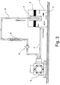
- the device comprises a tank (1) in which there is a volume of water (2) and crude oil (3).
- the latter having a lower density than the water, tends to stratify above the volume of water (2).
- a filter (4) made of sintered steel, having the form of a hollow cylinder closed below, is immersed in the tank (1).
- a first pipe (5) connected to a pump (6) is inserted inside said filter (4), which allows to suck the crude oil which permeates through the walls of the filter (4).
- the pump (6) is in turn connected by means of a second pipe (7) to the tank (1), in order to allow the re-entry of the crude oil into the tank (1).
- a flow-rate meter (8) is present along the pipe (5), which measures the volume of crude oil removed by means of the permeation process through the filter (4).
- the first pipe (5) is equipped with a valve (9) for regulating the inflow of the crude oil recovered.
- This apparatus (20) comprises a plurality of filtering devices (21), each having a filtering element (22) inserted in a hollow structure (23) suitable for receiving the hydrocarbon phase which permeates through the filtering element (22).
- Each hollow structure (23) can be possibly equipped with floating devices (not represented in Figure 4 ) which allow said structure to float on the body of water (24) with a floating line in correspondence with the filtering element (22), to allow the permeation of the hydrocarbons (25) present on the surface of the body of water (24).
- Each hollow structure (23) is connected by means of suitable ducts to a pump (26), which discharges the permeate collected into a collection tank (27), from which the hydrocarbons can be recovered.
- the filter was used as obtained from the supplier, without further cleaning treatment in addition to that effected by the producer according to the Swagelok, Standard Cleaning and Packaging SC-10 protocol.
- the filter was surface-treated with polydimethylsiloxane (PDMS) as follows.
- PDMS polydimethylsiloxane
- the base and crosslinking agent which form the product Sylgard® 184 Silicone Elastomer Kit (Dow Corning), were mixed in a ratio of 10:1 by volume and left to react at 70°C for about 1 hour, so as to obtain PDMS as a rubbery solid. This was then granulated with a cutter in order to obtain irregular-shaped particles having a particle-size distribution as indicated in Table 1 below: TABLE 1 Particle diameter (mm) Quantity of particles (weight %) > 4 81 4 - 2.8 17 2.8 - 2.36 1 ⁇ 2.36 1
- the hydrophobizing treatment was effected by inserting the filter in a muffle in which a container was positioned, closed by a lid having a vent, filled with PDMs prepared as described above.
- the muffle was heated at 250°C for 30 minutes.
- the outer surface of the immersed filter is in contact with gasoil and water in a 50:50 ratio.
- the specific flow of gasoil sucked by the pump (6) was measured with time, by means of the flow-rate meter (8).
- the water content Karl Fischer method was determined on samples of the gasoil removed, collected at different times. The results are indicated in Table 2.
- the treatment of the sintered filter allows a selective permeation of the gasoil from a water/gasoil mixture, which is substantially constant with time.
- the filter was subjected to hydrophobizing treatment with PDMS as described in Example 1 (weight variation +84 ⁇ g/g, expressed as an increase in weight of the filter against the hydrophobizing treatment, in micrograms per gram of filter).
- the treatment of the sintered filter allows a selective permeation of the crude oil from a water/crude oil mixture, which is substantially constant with time.
- Example 2 compared with Example 2, it can be seen that the use of seawater, in substitution of demineralized water, did not cause any significant variations in the permeability and selectivity of the filtering material.
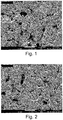
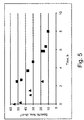
- Example 2 The specific flow of the crude oil removed was measured at increasing ⁇ p values, using a pneumatic system for generating the pressure difference. Filters of the same type indicated in Example 1 were used, having average pore dimensions equal to 15 ⁇ m, 60 ⁇ m and 90 ⁇ m, pretreated with PDMS according to the procedure described in Example 1. The outer surface of each filter immersed was exposed to crude oil and water in a ratio of 50:50 for the 60 and 90 ⁇ m filters, and in a ratio of 60:40 for the 15 ⁇ m filter.
- Figures 1 and 2 enclosed with the present description show two SEM images relating to the surface of the filter having an average pore-size equal to 15 ⁇ m, taken before treatment with PDMS ( Figure 1 ) and after treatment ( Figure 2 ). On comparing these images, no difference is observed between the surface before and after the treatment with PDMS.
- the photoemission spectrum (XPS) of the filter treated with PDMS showed a significant increase in the signal relating to silicon and oxygen, elements of which PDMS is composed, with respect to the non-treated filter.
- the filter was subjected to hydrophobizing treatment with PDMS as described in Example 1, except for the fact that the treatment was continued for 2 hours.
- the permeation test was carried out as described in Example 1, using the same type of water and gasoil, with an outer surface of the immersed filter in contact with gasoil and water in a ratio of 40:60.
- the specific flow of gasoil sucked by the pump (6) was measured with time, by means of the flow-rate meter (8). The results are indicated in Table 6.
- the filter was subjected to hydrophobizing treatment with PDMS as described in Example 1, except for the fact that the treatment was continued for 2 hours.
- the filters were used as received from the supplier, without preliminary washings.
- the Gooch filter having a the form of a glass with non-filtering flared walls and a filtering bottom, was tilted by 45° and the hydrocarbon/water mixture was poured into the upper part of the filter, so as to obtain a contact of the filtering bottom with both phases.
- the permeate was collected from the lower part of the filter and subjected to analysis. The tests were effected with the same type of water and gasoil as Example 1.
- Example 7 was repeated under the same conditions and with the same materials, except for the fact that the sintered glass filters were not subjected to hydrophobizing treatment. It was observed that these filters are selective with respect to water permeation, i.e. permeation through the filters of the aqueous phase alone was observed, without any phase separation in the permeate. Also in this case, the flow increases with an increase in the average pore diameter.
- the filter was subjected to hydrophobizing treatment with PDMS as described in Example 1, except for the fact that the treatment was continued for 2 hours.
Landscapes
- Chemical & Material Sciences (AREA)
- Life Sciences & Earth Sciences (AREA)
- Organic Chemistry (AREA)
- Water Supply & Treatment (AREA)
- Hydrology & Water Resources (AREA)
- Engineering & Computer Science (AREA)
- Environmental & Geological Engineering (AREA)
- Chemical Kinetics & Catalysis (AREA)
- Inorganic Chemistry (AREA)
- Geology (AREA)
- Health & Medical Sciences (AREA)
- Medicinal Chemistry (AREA)
- Analytical Chemistry (AREA)
- Filtering Materials (AREA)
- Separation Using Semi-Permeable Membranes (AREA)
- Production Of Liquid Hydrocarbon Mixture For Refining Petroleum (AREA)
Claims (16)
- Procédé pour retirer des hydrocarbures de manière pratiquement continue d'une étendue d'eau, comportant les étapes suivantes :- plonger dans ladite étendue d'eau au moins un filtre, présentant une structure creuse ou inséré en tant que fenêtre filtrante dans une structure creuse, lequel filtre est en un alliage métallique poreux et fritté dans lequel le diamètre moyen des pores vaut de 10 à 150 µm, et a subi un traitement de surface avec au moins un produit hydrophobe,- maintenir les hydrocarbures en contact avec une surface externe dudit filtre au nombre d'au moins un, afin de laisser les hydrocarbures traverser sélectivement par perméation ledit filtre au nombre d'au moins un et passer ainsi de ladite surface externe vers une surface interne du filtre, étant entendu qu'entre la surface externe du filtre, au contact des hydrocarbures à éliminer, et la surface interne du filtre, il règne une différence de pression (Δp) inférieure à 100 mbar,- et retirer, au moyen d'un dispositif d'aspiration, la phase d'hydrocarbures ayant, par perméation, traversé ledit filtre au nombre d'au moins un.
- Procédé conforme à la revendication 1, dans lequel ledit alliage métallique fritté est un acier, un acier inoxydable ou un alliage de nickel.
- Procédé conforme à l'une des revendications précédentes, dans lequel ledit produit hydrophobe au nombre d'au moins un est un produit organique de type hydrocarbure, éventuellement au moins partiellement fluoré, ou un produit dérivé du silicium.
- Procédé conforme à l'une des revendications précédentes, dans lequel ledit produit hydrophobe au nombre d'au moins un est choisi parmi les suivants : hydrocarbures à masse molaire élevée, de préférence porteurs de substituants qui sont des groupes fonctionnels capables d'interagir avec le matériau formant le filtre, polyoléfines, polystyrènes, poly(acrylate d'alkyle)s, poly(méthacrylate d'alkyle)s, silanes comportant au moins un groupe alkyle ou fluoroalkyle, et polysiloxanes.
- Procédé conforme à l'une des revendications précédentes, dans lequel il règne, entre la surface externe du filtre au contact des hydrocarbures à éliminer et la surface interne du filtre, une différence de pression (Δp) inférieure à 20 mbar.
- Procédé conforme à la revendication 5, dans lequel ladite différence de pression est pratiquement nulle.
- Procédé conforme à l'une des revendications précédentes, dans lequel ledit filtre, au nombre d'au moins un, en matériau fritté est doté d'une structure creuse qui délimite un espace interne dans lequel sont collectés les hydrocarbures qui ont traversé le filtre par perméation et duquel ceux-ci sont retirés.
- Procédé conforme à l'une des revendications 1 à 6 précédentes, dans lequel ledit filtre, au nombre d'au moins un, en matériau fritté est inséré en tant que fenêtre filtrante dans une structure creuse qui permet de collecter les hydrocarbures pénétrant par perméation à l'intérieur de ladite structure.
- Procédé conforme à l'une des revendications précédentes, qui comprend en outre une étape de lavage du filtre, après une durée d'utilisation fixée au préalable.
- Procédé conforme à la revendication 9, dans lequel ladite étape de lavage est réalisée sous la forme d'un rétro-lavage effectué à l'aide d'un solvant organique propre à dissoudre les hydrocarbures.
- Appareil servant à retirer des hydrocarbures de manière pratiquement continue d'une étendue d'eau, comportant :- au moins un filtre, présentant une structure creuse ou inséré en tant que fenêtre filtrante dans une structure creuse, lequel filtre est en un alliage métallique poreux et fritté dans lequel le diamètre moyen des pores vaut de 10 à 150 µm, et a subi un traitement de surface avec au moins un produit hydrophobe,- et au moins un dispositif d'aspiration servant à retirer la phase d'hydrocarbures ayant, par perméation, traversé ledit filtre au nombre d'au moins un.
- Appareil conforme à la revendication 11, dans lequel ledit alliage métallique fritté est un acier, un acier inoxydable ou un alliage de nickel.
- Appareil conforme à l'une des revendications 11 à 12, dans lequel ledit produit hydrophobe au nombre d'au moins un est un produit organique de type hydrocarbure, éventuellement au moins partiellement fluoré, ou un produit dérivé du silicium.
- Appareil conforme à l'une des revendications 11 à 13, dans lequel ledit produit hydrophobe au nombre d'au moins un est choisi parmi les suivants : hydrocarbures à masse molaire élevée, de préférence porteurs de substituants qui sont des groupes fonctionnels capables d'interagir avec le matériau formant le filtre, polyoléfines, polystyrènes, poly(acrylate d'alkyle)s, poly(méthacrylate d'alkyle)s, silanes comportant au moins un groupe alkyle ou fluoroalkyle, et polysiloxanes.
- Appareil conforme à l'une des revendications 11 à 14, dans lequel ledit filtre, au nombre d'au moins un, en matériau fritté est doté d'une structure creuse qui délimite un espace interne dans lequel sont collectés les hydrocarbures qui ont traversé le filtre par perméation et duquel ceux-ci sont retirés.
- Appareil conforme à l'une des revendications 11 à 15, dans lequel ledit filtre, au nombre d'au moins un, en matériau fritté est inséré en tant que fenêtre filtrante dans une structure creuse qui permet de collecter les hydrocarbures pénétrant par perméation à l'intérieur de ladite structure.
Priority Applications (1)
| Application Number | Priority Date | Filing Date | Title |
|---|---|---|---|
| PL13828878T PL2938574T3 (pl) | 2012-12-28 | 2013-12-27 | Sposób usuwania węglowodorów z masy wody na drodze selektywnego przepuszczania i stosowny aparat |
Applications Claiming Priority (2)
| Application Number | Priority Date | Filing Date | Title |
|---|---|---|---|
| IT002254A ITMI20122254A1 (it) | 2012-12-28 | 2012-12-28 | Processo per la rimozione di idrocarburi da un corpo d'acqua tramite permeazione selettiva, e relativo apparato |
| PCT/IB2013/061359 WO2014102736A1 (fr) | 2012-12-28 | 2013-12-27 | Procédé de retrait d'hydrocarbures d'un plan d'eau par perméation sélective et appareil associé |
Publications (2)
| Publication Number | Publication Date |
|---|---|
| EP2938574A1 EP2938574A1 (fr) | 2015-11-04 |
| EP2938574B1 true EP2938574B1 (fr) | 2018-09-05 |
Family
ID=47720675
Family Applications (1)
| Application Number | Title | Priority Date | Filing Date |
|---|---|---|---|
| EP13828878.2A Active EP2938574B1 (fr) | 2012-12-28 | 2013-12-27 | Procédé de retrait d'hydrocarbures d'un plan d'eau par perméation sélective et appareil associé |
Country Status (7)
| Country | Link |
|---|---|
| US (1) | US20150321925A1 (fr) |
| EP (1) | EP2938574B1 (fr) |
| ES (1) | ES2700228T3 (fr) |
| IT (1) | ITMI20122254A1 (fr) |
| PL (1) | PL2938574T3 (fr) |
| PT (1) | PT2938574T (fr) |
| WO (1) | WO2014102736A1 (fr) |
Families Citing this family (5)
| Publication number | Priority date | Publication date | Assignee | Title |
|---|---|---|---|---|
| US9718703B2 (en) * | 2014-09-10 | 2017-08-01 | I Shou University | Apparatus and method for continuously removing oily pollutant from polluted water using hydrophobic/oleophilic absorbent article |
| WO2016067178A1 (fr) * | 2014-10-27 | 2016-05-06 | Eni S.P.A. | Procédé d'élimination d'hydrocarbures d'un corps aqueux par perméation sélective, et appareil associé |
| GB201520964D0 (en) * | 2015-11-27 | 2016-01-13 | Porvair Filtration Group Ltd | Filtration material and method of manufacture thereof |
| WO2018014465A1 (fr) * | 2016-07-22 | 2018-01-25 | Nv Bekaert Sa | Milieu de filtration et filtre coalescent pour éliminer l'eau à partir des hydrocarbures liquides |
| KR102653462B1 (ko) * | 2021-11-03 | 2024-03-29 | 한남대학교 산학협력단 | 폴리우레탄 스폰지를 사용한 오일 흡수제의 제조방법 |
Citations (1)
| Publication number | Priority date | Publication date | Assignee | Title |
|---|---|---|---|---|
| CA2227520A1 (fr) * | 1998-03-31 | 1999-09-30 | Zihijia Hurem | Filtre actif compose de materiau composite a grillage agglomerant et procede de separation de matiere organique hydrophobe du sol et de fluides aqueux en utilisant des tensions d'interface controlees et la dimension des pores |
Family Cites Families (18)
| Publication number | Priority date | Publication date | Assignee | Title |
|---|---|---|---|---|
| US2552133A (en) * | 1948-07-13 | 1951-05-08 | Becker George | Sewing machine guide attachment |
| DE1195220B (de) * | 1964-11-13 | 1965-06-16 | Perlite G M B H Deutsche | Verwendung von Perlite zum Aufsaugen von auf Wasser schwimmendem OEl |
| US3784010A (en) | 1972-08-23 | 1974-01-08 | Black Sivalls & Bryson Inc | Apparatus for separating oil and solids from water |
| US4325846A (en) * | 1980-01-30 | 1982-04-20 | Kozo Shibata | Adsorbent materials for oils and fats |
| IT8167809A0 (it) | 1980-06-23 | 1981-06-11 | Chicago Rawhide Mfg Co | Dispositivo per la rimozione di sostanze contaminanti da un fluido |
| FR2552133B1 (fr) | 1983-09-15 | 1986-09-26 | Impal Expansion Duby Gros | Barrage modulaire filtrant contre la pollution des eaux |
| US4732671A (en) | 1986-08-04 | 1988-03-22 | Allied Corporation | Diesel fuel filter/water separator |
| US5293935A (en) * | 1990-10-22 | 1994-03-15 | Halliburton Company | Sintered metal substitute for prepack screen aggregate |
| JPH08134508A (ja) * | 1994-11-10 | 1996-05-28 | Asahi Tec Corp | 多孔質金属の製造方法 |
| US5558777A (en) | 1995-04-13 | 1996-09-24 | Rheox, Inc. | Oil spill flocculating agent and method of remediating oil spills |
| IT1287754B1 (it) | 1996-07-25 | 1998-08-18 | Universal Filter Spa | Filtro per carburante, in particolare carburante per motori diesel |
| JPH10244254A (ja) * | 1997-03-03 | 1998-09-14 | Asahi Tec Corp | 油水分離材及びそれを用いた油水分離方法 |
| GB0421320D0 (en) | 2004-09-27 | 2004-10-27 | Invert Group Ltd | A separator |
| US8591952B2 (en) * | 2006-10-10 | 2013-11-26 | Massachusetts Institute Of Technology | Absorbant superhydrophobic materials, and methods of preparation and use thereof |
| US9795897B2 (en) | 2006-11-08 | 2017-10-24 | Donaldson Company, Inc. | Systems, articles, and methods for removing water from hydrocarbon fluids |
| US8978899B2 (en) * | 2007-08-01 | 2015-03-17 | Donaldson Company, Inc. | Fluoropolymer fine fiber |
| JP5422525B2 (ja) * | 2010-09-03 | 2014-02-19 | 株式会社東芝 | 排水処理方法 |
| US10865127B2 (en) * | 2012-10-03 | 2020-12-15 | Massachusetts Institute Of Technology | Liquid separation device comprising a metallic mesh with a hydrophobic polymer coating |
-
2012
- 2012-12-28 IT IT002254A patent/ITMI20122254A1/it unknown
-
2013
- 2013-12-27 ES ES13828878T patent/ES2700228T3/es active Active
- 2013-12-27 EP EP13828878.2A patent/EP2938574B1/fr active Active
- 2013-12-27 PT PT13828878T patent/PT2938574T/pt unknown
- 2013-12-27 US US14/649,406 patent/US20150321925A1/en not_active Abandoned
- 2013-12-27 PL PL13828878T patent/PL2938574T3/pl unknown
- 2013-12-27 WO PCT/IB2013/061359 patent/WO2014102736A1/fr not_active Ceased
Patent Citations (1)
| Publication number | Priority date | Publication date | Assignee | Title |
|---|---|---|---|---|
| CA2227520A1 (fr) * | 1998-03-31 | 1999-09-30 | Zihijia Hurem | Filtre actif compose de materiau composite a grillage agglomerant et procede de separation de matiere organique hydrophobe du sol et de fluides aqueux en utilisant des tensions d'interface controlees et la dimension des pores |
Also Published As
| Publication number | Publication date |
|---|---|
| EP2938574A1 (fr) | 2015-11-04 |
| US20150321925A1 (en) | 2015-11-12 |
| PT2938574T (pt) | 2018-12-11 |
| WO2014102736A1 (fr) | 2014-07-03 |
| ITMI20122254A1 (it) | 2014-06-29 |
| PL2938574T3 (pl) | 2019-03-29 |
| ES2700228T3 (es) | 2019-02-14 |
Similar Documents
| Publication | Publication Date | Title |
|---|---|---|
| Zhang et al. | Reduced graphene-based superhydrophobic sponges modified by hexadecyltrimethoxysilane for oil adsorption | |
| EP2938574B1 (fr) | Procédé de retrait d'hydrocarbures d'un plan d'eau par perméation sélective et appareil associé | |
| Bigui et al. | Fabrication of superhydrophilic and underwater superoleophobic quartz sand filter for oil/water separation | |
| Parsaie et al. | Magnesium stearate-coated superhydrophobic sponge for oil/water separation: Synthesis, properties, application | |
| Wen et al. | Zeolite-coated mesh film for efficient oil–water separation | |
| Lu et al. | Development of coin-shaped ZIF-7 functionalized superhydrophobic polysulfone composite foams for continuous removal of oily contaminants from water | |
| Olalekan et al. | Silica aerogel as a viable absorbent for oil spill remediation | |
| CN107312198A (zh) | 超疏水海绵体及其制备方法 | |
| WO2021250515A1 (fr) | Composite janus pour séparation d'huile dans l'eau | |
| WO2008060940A2 (fr) | Fluidisation inverse pour purification de courants fluidiques | |
| Paul et al. | Carbon nanotube enhanced membrane filtration for trace level dewatering of hydrocarbons | |
| Shahmirzaee et al. | Magnetic γ-Fe2O3/ZIF-7 composite particles and their application for oily water treatment | |
| CN107312196A (zh) | 超疏水海绵材料及其制备方法 | |
| Pandey et al. | Sustainable lotus leaf wax nanocuticles integrated polydimethylsiloxane sorbent for instant removal of oily waste from water | |
| Wang et al. | Bi-functional composite foam with hierarchical structure for efficient separation of emulsified mixtures consisting of oil and water | |
| Mosayebi et al. | Fabrication of highly hydrophobic sand@ soot with core–shell structure and large-scale production possibility for oil/water separation | |
| Dashairya et al. | Zirconium diboride assisted superhydrophobic/superoleophilic surface modification of polyurethane sponge for continuous oil-water separation and emulsion purification | |
| Li et al. | Tannic acid modified zeolitic imidazolate framework-8 membrane with macrosized cavities for efficient oil-in-water emulsion separation | |
| US20240254014A1 (en) | System for separating oil and water mixture using hydrophilic modified polystyrene and hydrophobic polyurethane | |
| US12496556B2 (en) | Method for separating an oil-water emulsion | |
| WO2016067178A1 (fr) | Procédé d'élimination d'hydrocarbures d'un corps aqueux par perméation sélective, et appareil associé | |
| Meresht et al. | Fabrication of super-hydrophobic and super-oleophilic melamine sponge functionalized by acrylic resin/silica nanoparticles for oil/water selective separation: A RSM@ BBD optimization approach | |
| Urmitova et al. | Oil-containing wastewater treatment by means of using coarse-grained coalescing filtering materials | |
| Moslehyani et al. | PVDF membrane for oil-in-water separation via cross-flow ultrafiltration process | |
| Zhong et al. | Underwater superoleophobic membrane with hydrophobic bump and hydrophilic sublayer structure for effective oil-in-water emulsions separation |
Legal Events
| Date | Code | Title | Description |
|---|---|---|---|
| PUAI | Public reference made under article 153(3) epc to a published international application that has entered the european phase |
Free format text: ORIGINAL CODE: 0009012 |
|
| 17P | Request for examination filed |
Effective date: 20150604 |
|
| AK | Designated contracting states |
Kind code of ref document: A1 Designated state(s): AL AT BE BG CH CY CZ DE DK EE ES FI FR GB GR HR HU IE IS IT LI LT LU LV MC MK MT NL NO PL PT RO RS SE SI SK SM TR |
|
| AX | Request for extension of the european patent |
Extension state: BA ME |
|
| DAX | Request for extension of the european patent (deleted) | ||
| 17Q | First examination report despatched |
Effective date: 20160915 |
|
| STAA | Information on the status of an ep patent application or granted ep patent |
Free format text: STATUS: EXAMINATION IS IN PROGRESS |
|
| GRAP | Despatch of communication of intention to grant a patent |
Free format text: ORIGINAL CODE: EPIDOSNIGR1 |
|
| STAA | Information on the status of an ep patent application or granted ep patent |
Free format text: STATUS: GRANT OF PATENT IS INTENDED |
|
| INTG | Intention to grant announced |
Effective date: 20180328 |
|
| GRAS | Grant fee paid |
Free format text: ORIGINAL CODE: EPIDOSNIGR3 |
|
| GRAA | (expected) grant |
Free format text: ORIGINAL CODE: 0009210 |
|
| STAA | Information on the status of an ep patent application or granted ep patent |
Free format text: STATUS: THE PATENT HAS BEEN GRANTED |
|
| AK | Designated contracting states |
Kind code of ref document: B1 Designated state(s): AL AT BE BG CH CY CZ DE DK EE ES FI FR GB GR HR HU IE IS IT LI LT LU LV MC MK MT NL NO PL PT RO RS SE SI SK SM TR |
|
| REG | Reference to a national code |
Ref country code: GB Ref legal event code: FG4D |
|
| REG | Reference to a national code |
Ref country code: CH Ref legal event code: EP |
|
| REG | Reference to a national code |
Ref country code: AT Ref legal event code: REF Ref document number: 1037574 Country of ref document: AT Kind code of ref document: T Effective date: 20180915 |
|
| REG | Reference to a national code |
Ref country code: IE Ref legal event code: FG4D |
|
| REG | Reference to a national code |
Ref country code: DE Ref legal event code: R096 Ref document number: 602013043307 Country of ref document: DE |
|
| REG | Reference to a national code |
Ref country code: PT Ref legal event code: SC4A Ref document number: 2938574 Country of ref document: PT Date of ref document: 20181211 Kind code of ref document: T Free format text: AVAILABILITY OF NATIONAL TRANSLATION Effective date: 20181203 |
|
| REG | Reference to a national code |
Ref country code: NL Ref legal event code: FP |
|
| REG | Reference to a national code |
Ref country code: SE Ref legal event code: TRGR |
|
| REG | Reference to a national code |
Ref country code: CH Ref legal event code: NV Representative=s name: BOHEST AG, CH |
|
| REG | Reference to a national code |
Ref country code: LT Ref legal event code: MG4D |
|
| REG | Reference to a national code |
Ref country code: NO Ref legal event code: T2 Effective date: 20180905 |
|
| PG25 | Lapsed in a contracting state [announced via postgrant information from national office to epo] |
Ref country code: BG Free format text: LAPSE BECAUSE OF FAILURE TO SUBMIT A TRANSLATION OF THE DESCRIPTION OR TO PAY THE FEE WITHIN THE PRESCRIBED TIME-LIMIT Effective date: 20181205 Ref country code: LT Free format text: LAPSE BECAUSE OF FAILURE TO SUBMIT A TRANSLATION OF THE DESCRIPTION OR TO PAY THE FEE WITHIN THE PRESCRIBED TIME-LIMIT Effective date: 20180905 Ref country code: GR Free format text: LAPSE BECAUSE OF FAILURE TO SUBMIT A TRANSLATION OF THE DESCRIPTION OR TO PAY THE FEE WITHIN THE PRESCRIBED TIME-LIMIT Effective date: 20181206 Ref country code: RS Free format text: LAPSE BECAUSE OF FAILURE TO SUBMIT A TRANSLATION OF THE DESCRIPTION OR TO PAY THE FEE WITHIN THE PRESCRIBED TIME-LIMIT Effective date: 20180905 Ref country code: FI Free format text: LAPSE BECAUSE OF FAILURE TO SUBMIT A TRANSLATION OF THE DESCRIPTION OR TO PAY THE FEE WITHIN THE PRESCRIBED TIME-LIMIT Effective date: 20180905 |
|
| REG | Reference to a national code |
Ref country code: ES Ref legal event code: FG2A Ref document number: 2700228 Country of ref document: ES Kind code of ref document: T3 Effective date: 20190214 |
|
| PG25 | Lapsed in a contracting state [announced via postgrant information from national office to epo] |
Ref country code: AL Free format text: LAPSE BECAUSE OF FAILURE TO SUBMIT A TRANSLATION OF THE DESCRIPTION OR TO PAY THE FEE WITHIN THE PRESCRIBED TIME-LIMIT Effective date: 20180905 Ref country code: HR Free format text: LAPSE BECAUSE OF FAILURE TO SUBMIT A TRANSLATION OF THE DESCRIPTION OR TO PAY THE FEE WITHIN THE PRESCRIBED TIME-LIMIT Effective date: 20180905 Ref country code: LV Free format text: LAPSE BECAUSE OF FAILURE TO SUBMIT A TRANSLATION OF THE DESCRIPTION OR TO PAY THE FEE WITHIN THE PRESCRIBED TIME-LIMIT Effective date: 20180905 |
|
| PG25 | Lapsed in a contracting state [announced via postgrant information from national office to epo] |
Ref country code: RO Free format text: LAPSE BECAUSE OF FAILURE TO SUBMIT A TRANSLATION OF THE DESCRIPTION OR TO PAY THE FEE WITHIN THE PRESCRIBED TIME-LIMIT Effective date: 20180905 Ref country code: EE Free format text: LAPSE BECAUSE OF FAILURE TO SUBMIT A TRANSLATION OF THE DESCRIPTION OR TO PAY THE FEE WITHIN THE PRESCRIBED TIME-LIMIT Effective date: 20180905 Ref country code: IS Free format text: LAPSE BECAUSE OF FAILURE TO SUBMIT A TRANSLATION OF THE DESCRIPTION OR TO PAY THE FEE WITHIN THE PRESCRIBED TIME-LIMIT Effective date: 20190105 |
|
| PG25 | Lapsed in a contracting state [announced via postgrant information from national office to epo] |
Ref country code: SM Free format text: LAPSE BECAUSE OF FAILURE TO SUBMIT A TRANSLATION OF THE DESCRIPTION OR TO PAY THE FEE WITHIN THE PRESCRIBED TIME-LIMIT Effective date: 20180905 Ref country code: SK Free format text: LAPSE BECAUSE OF FAILURE TO SUBMIT A TRANSLATION OF THE DESCRIPTION OR TO PAY THE FEE WITHIN THE PRESCRIBED TIME-LIMIT Effective date: 20180905 |
|
| REG | Reference to a national code |
Ref country code: DE Ref legal event code: R097 Ref document number: 602013043307 Country of ref document: DE |
|
| PLBE | No opposition filed within time limit |
Free format text: ORIGINAL CODE: 0009261 |
|
| STAA | Information on the status of an ep patent application or granted ep patent |
Free format text: STATUS: NO OPPOSITION FILED WITHIN TIME LIMIT |
|
| PG25 | Lapsed in a contracting state [announced via postgrant information from national office to epo] |
Ref country code: DK Free format text: LAPSE BECAUSE OF FAILURE TO SUBMIT A TRANSLATION OF THE DESCRIPTION OR TO PAY THE FEE WITHIN THE PRESCRIBED TIME-LIMIT Effective date: 20180905 |
|
| 26N | No opposition filed |
Effective date: 20190606 |
|
| PG25 | Lapsed in a contracting state [announced via postgrant information from national office to epo] |
Ref country code: MC Free format text: LAPSE BECAUSE OF FAILURE TO SUBMIT A TRANSLATION OF THE DESCRIPTION OR TO PAY THE FEE WITHIN THE PRESCRIBED TIME-LIMIT Effective date: 20180905 Ref country code: LU Free format text: LAPSE BECAUSE OF NON-PAYMENT OF DUE FEES Effective date: 20181227 Ref country code: SI Free format text: LAPSE BECAUSE OF FAILURE TO SUBMIT A TRANSLATION OF THE DESCRIPTION OR TO PAY THE FEE WITHIN THE PRESCRIBED TIME-LIMIT Effective date: 20180905 |
|
| REG | Reference to a national code |
Ref country code: IE Ref legal event code: MM4A |
|
| PG25 | Lapsed in a contracting state [announced via postgrant information from national office to epo] |
Ref country code: IE Free format text: LAPSE BECAUSE OF NON-PAYMENT OF DUE FEES Effective date: 20181227 |
|
| PG25 | Lapsed in a contracting state [announced via postgrant information from national office to epo] |
Ref country code: MT Free format text: LAPSE BECAUSE OF NON-PAYMENT OF DUE FEES Effective date: 20181227 |
|
| PG25 | Lapsed in a contracting state [announced via postgrant information from national office to epo] |
Ref country code: TR Free format text: LAPSE BECAUSE OF FAILURE TO SUBMIT A TRANSLATION OF THE DESCRIPTION OR TO PAY THE FEE WITHIN THE PRESCRIBED TIME-LIMIT Effective date: 20180905 |
|
| REG | Reference to a national code |
Ref country code: AT Ref legal event code: UEP Ref document number: 1037574 Country of ref document: AT Kind code of ref document: T Effective date: 20180905 |
|
| PG25 | Lapsed in a contracting state [announced via postgrant information from national office to epo] |
Ref country code: MK Free format text: LAPSE BECAUSE OF NON-PAYMENT OF DUE FEES Effective date: 20180905 Ref country code: HU Free format text: LAPSE BECAUSE OF FAILURE TO SUBMIT A TRANSLATION OF THE DESCRIPTION OR TO PAY THE FEE WITHIN THE PRESCRIBED TIME-LIMIT; INVALID AB INITIO Effective date: 20131227 Ref country code: CY Free format text: LAPSE BECAUSE OF FAILURE TO SUBMIT A TRANSLATION OF THE DESCRIPTION OR TO PAY THE FEE WITHIN THE PRESCRIBED TIME-LIMIT Effective date: 20180905 |
|
| P01 | Opt-out of the competence of the unified patent court (upc) registered |
Effective date: 20230609 |
|
| PGFP | Annual fee paid to national office [announced via postgrant information from national office to epo] |
Ref country code: CH Payment date: 20250101 Year of fee payment: 12 |
|
| REG | Reference to a national code |
Ref country code: CH Ref legal event code: U11 Free format text: ST27 STATUS EVENT CODE: U-0-0-U10-U11 (AS PROVIDED BY THE NATIONAL OFFICE) Effective date: 20260101 |
|
| PGFP | Annual fee paid to national office [announced via postgrant information from national office to epo] |
Ref country code: GB Payment date: 20251229 Year of fee payment: 13 |
|
| PGFP | Annual fee paid to national office [announced via postgrant information from national office to epo] |
Ref country code: NO Payment date: 20251231 Year of fee payment: 13 |
|
| PGFP | Annual fee paid to national office [announced via postgrant information from national office to epo] |
Ref country code: AT Payment date: 20251230 Year of fee payment: 13 Ref country code: PT Payment date: 20251211 Year of fee payment: 13 |
|
| PGFP | Annual fee paid to national office [announced via postgrant information from national office to epo] |
Ref country code: IT Payment date: 20251219 Year of fee payment: 13 |
|
| PGFP | Annual fee paid to national office [announced via postgrant information from national office to epo] |
Ref country code: FR Payment date: 20251226 Year of fee payment: 13 Ref country code: NL Payment date: 20251226 Year of fee payment: 13 |
|
| PGFP | Annual fee paid to national office [announced via postgrant information from national office to epo] |
Ref country code: BE Payment date: 20251229 Year of fee payment: 13 |
|
| PGFP | Annual fee paid to national office [announced via postgrant information from national office to epo] |
Ref country code: SE Payment date: 20251227 Year of fee payment: 13 |
|
| PGFP | Annual fee paid to national office [announced via postgrant information from national office to epo] |
Ref country code: CZ Payment date: 20251208 Year of fee payment: 13 |
|
| PGFP | Annual fee paid to national office [announced via postgrant information from national office to epo] |
Ref country code: PL Payment date: 20251202 Year of fee payment: 13 |
|
| PGFP | Annual fee paid to national office [announced via postgrant information from national office to epo] |
Ref country code: ES Payment date: 20260102 Year of fee payment: 13 |
|
| PGFP | Annual fee paid to national office [announced via postgrant information from national office to epo] |
Ref country code: DE Payment date: 20251229 Year of fee payment: 13 |