EP2938849B1 - Organe d'echappement pour moteur a combustion interne - Google Patents
Organe d'echappement pour moteur a combustion interne Download PDFInfo
- Publication number
- EP2938849B1 EP2938849B1 EP13785553.2A EP13785553A EP2938849B1 EP 2938849 B1 EP2938849 B1 EP 2938849B1 EP 13785553 A EP13785553 A EP 13785553A EP 2938849 B1 EP2938849 B1 EP 2938849B1
- Authority
- EP
- European Patent Office
- Prior art keywords
- sheet
- exhaust member
- exhaust
- welded
- inlet duct
- Prior art date
- Legal status (The legal status is an assumption and is not a legal conclusion. Google has not performed a legal analysis and makes no representation as to the accuracy of the status listed.)
- Active
Links
Images


Classifications
-
- F—MECHANICAL ENGINEERING; LIGHTING; HEATING; WEAPONS; BLASTING
- F01—MACHINES OR ENGINES IN GENERAL; ENGINE PLANTS IN GENERAL; STEAM ENGINES
- F01N—GAS-FLOW SILENCERS OR EXHAUST APPARATUS FOR MACHINES OR ENGINES IN GENERAL; GAS-FLOW SILENCERS OR EXHAUST APPARATUS FOR INTERNAL-COMBUSTION ENGINES
- F01N13/00—Exhaust or silencing apparatus characterised by constructional features
- F01N13/08—Other arrangements or adaptations of exhaust conduits
- F01N13/10—Other arrangements or adaptations of exhaust conduits of exhaust manifolds
- F01N13/102—Other arrangements or adaptations of exhaust conduits of exhaust manifolds having thermal insulation
-
- F—MECHANICAL ENGINEERING; LIGHTING; HEATING; WEAPONS; BLASTING
- F01—MACHINES OR ENGINES IN GENERAL; ENGINE PLANTS IN GENERAL; STEAM ENGINES
- F01N—GAS-FLOW SILENCERS OR EXHAUST APPARATUS FOR MACHINES OR ENGINES IN GENERAL; GAS-FLOW SILENCERS OR EXHAUST APPARATUS FOR INTERNAL-COMBUSTION ENGINES
- F01N13/00—Exhaust or silencing apparatus characterised by constructional features
- F01N13/14—Exhaust or silencing apparatus characterised by constructional features having thermal insulation
-
- F—MECHANICAL ENGINEERING; LIGHTING; HEATING; WEAPONS; BLASTING
- F01—MACHINES OR ENGINES IN GENERAL; ENGINE PLANTS IN GENERAL; STEAM ENGINES
- F01N—GAS-FLOW SILENCERS OR EXHAUST APPARATUS FOR MACHINES OR ENGINES IN GENERAL; GAS-FLOW SILENCERS OR EXHAUST APPARATUS FOR INTERNAL-COMBUSTION ENGINES
- F01N13/00—Exhaust or silencing apparatus characterised by constructional features
- F01N13/14—Exhaust or silencing apparatus characterised by constructional features having thermal insulation
- F01N13/141—Double-walled exhaust pipes or housings
-
- F—MECHANICAL ENGINEERING; LIGHTING; HEATING; WEAPONS; BLASTING
- F01—MACHINES OR ENGINES IN GENERAL; ENGINE PLANTS IN GENERAL; STEAM ENGINES
- F01N—GAS-FLOW SILENCERS OR EXHAUST APPARATUS FOR MACHINES OR ENGINES IN GENERAL; GAS-FLOW SILENCERS OR EXHAUST APPARATUS FOR INTERNAL-COMBUSTION ENGINES
- F01N13/00—Exhaust or silencing apparatus characterised by constructional features
- F01N13/14—Exhaust or silencing apparatus characterised by constructional features having thermal insulation
- F01N13/141—Double-walled exhaust pipes or housings
- F01N13/143—Double-walled exhaust pipes or housings with air filling the space between both walls
-
- F—MECHANICAL ENGINEERING; LIGHTING; HEATING; WEAPONS; BLASTING
- F02—COMBUSTION ENGINES; HOT-GAS OR COMBUSTION-PRODUCT ENGINE PLANTS
- F02B—INTERNAL-COMBUSTION PISTON ENGINES; COMBUSTION ENGINES IN GENERAL
- F02B67/00—Engines characterised by the arrangement of auxiliary apparatus not being otherwise provided for, e.g. the apparatus having different functions; Driving auxiliary apparatus from engines, not otherwise provided for
- F02B67/10—Engines characterised by the arrangement of auxiliary apparatus not being otherwise provided for, e.g. the apparatus having different functions; Driving auxiliary apparatus from engines, not otherwise provided for of charging or scavenging apparatus
-
- F—MECHANICAL ENGINEERING; LIGHTING; HEATING; WEAPONS; BLASTING
- F01—MACHINES OR ENGINES IN GENERAL; ENGINE PLANTS IN GENERAL; STEAM ENGINES
- F01N—GAS-FLOW SILENCERS OR EXHAUST APPARATUS FOR MACHINES OR ENGINES IN GENERAL; GAS-FLOW SILENCERS OR EXHAUST APPARATUS FOR INTERNAL-COMBUSTION ENGINES
- F01N2450/00—Methods or apparatus for fitting, inserting or repairing different elements
- F01N2450/22—Methods or apparatus for fitting, inserting or repairing different elements by welding or brazing
-
- F—MECHANICAL ENGINEERING; LIGHTING; HEATING; WEAPONS; BLASTING
- F02—COMBUSTION ENGINES; HOT-GAS OR COMBUSTION-PRODUCT ENGINE PLANTS
- F02B—INTERNAL-COMBUSTION PISTON ENGINES; COMBUSTION ENGINES IN GENERAL
- F02B37/00—Engines characterised by provision of pumps driven at least for part of the time by exhaust
Definitions
- the present invention relates to the automotive field and more particularly to internal combustion engines equipped with an integrated turbocharger.
- This type of engine includes an exhaust manifold connected to an inlet duct of a turbocharger
- the exhaust manifold is most often assembled to the cylinder head of the engine by means of a screw connection which joins the inlet flanges with the exhaust face of the cylinder head.
- a metal seal is interposed between the cylinder head and the inlet flanges of the exhaust manifold to provide a better seal to the exhaust gas.
- the exhaust manifold consists of two sheets and the turbocharger.
- the inner plate of the exhaust manifold and that of the turbocharger being connected either by a non-welded but fitted assembly at each junction between conduits, or with differential expansion compensators.
- the turbocharger is most often assembled to the exhaust manifold by means of a screw connection which joins the outlet flange of the exhaust manifold and the collector of the turbocharger.
- a metal seal is interposed between the turbo and the inlet flange of the exhaust manifold to provide a better seal to the exhaust gas.
- the manifold and the turbine housing are generally cast iron and connected by a flange with studs.
- the conduit between the turbo and the catalytic converter is generally sheet metal.
- the connection with the turbine is usually a flange with studs.
- the connection with the catalytic converter is usually a weld.
- This system makes it possible to reduce the thermal inertia of the system in order to prime the catalyst as much as possible, but the cost of this system remains relatively high today.
- the object of the present invention is to propose a solution which makes it possible to eliminate flanges which are bulky and which have a certain thermal inertia and which respond to the important thermal stresses of the exhaust manifold.
- the exhaust member of an internal combustion engine comprises an exhaust manifold with an internal sheet and an external sheet welded to a turbocharger by an inlet duct with an internal sheet and an outer sheet characterized in that the inner sheet of the inlet duct is welded to the outer sheet of the exhaust manifold and the inner sheet of the manifold is connected by a sliding connection to the inlet duct.
- the welding between the exhaust manifold and the inlet duct must make it possible to limit the mechanical stresses of thermal origin likely to cause cracks in the weld that can go as far as its destruction, this is why the inlet duct which proportionally has a lower temperature is connected to the outer sheet of the exhaust manifold which is also at a temperature lower than the inner sheet of the collector. Since the temperature difference is smaller between the different sheets welded together, the mechanical stresses of thermal origin are reduced accordingly.
- the slide connection of the inner plate of the collector with the inlet duct of the turbine casing gives it the possibility of expanding freely under the effect of heat.
- the outer sheet of the exhaust manifold is welded to the inner sheet of the inlet duct.
- the inner sheet is relatively cooler than the inner sheet of the collector.
- the outer sheet of the inlet duct is welded to the internal sheet of said duct.
- the outer sheet of the duct is thus not in contact with the inner sheet of the hottest collector.
- an expansion compensator is disposed between the two welds.
- the welding between the outer sheet of the manifold most exposed to heat is protected from the weld between the two sheets of the inlet duct by an expansion compensator which reduces the mechanical stresses due to the temperature differences of the two welds.
- an expansion compensator is disposed towards the turbine after the welding of the outer sheet of the inlet duct with the inner sheet of said duct.
- the expansion compensator placed between the weld and the bottom of the inner sheet of the conduit allows the weld not to be subjected to the mechanical stresses related to the heat of the internal sheet.
- a thermal insulator is disposed between the two sheets of the intake duct. This insulation allows the outer sheet of the intake duct to be less hot than the inner sheet.
- a thermal insulator is disposed between the two plates of the exhaust manifold. This insulation allows the outer sheet of the collector to be less hot than the inner sheet.
- the thermal insulation is air.
- Insulation can also be a solid insulator.
- the invention also relates to an internal combustion engine equipped with an exhaust member with one of the preceding characteristics.
- the internal combustion engine 1 illustrated in FIG. figure 1 comprises an internal combustion chamber (not shown), an exhaust manifold 2 and a turbocharger or turbo 3.
- the turbo 3 as the exhaust manifold 2 is double-walled, an inner sheet 20 for the collector 2 and a sheet internal 30 for the turbo 3 and an outer plate 21 for the collector 2 and an outer plate 31 for the turbo 3.
- the internal 30 and outer plates 31 of the turbo 3 are substantially cylindrical.
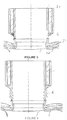
- the variant illustrated in figure 2 details the connection between the collector 2 and the turbo 3.
- the inner and outer laminations 20 and 21 of the collector each have an edge 200 and 210 of substantially Circular dimension substantially equal to the cylinder formed by the plates of the turbo 3.
- the edge 200 of the inner sheet 20 of the collector 2 is slid into the edge 210 of the outer sheet 21.
- the sheet 30 is slid into the edge 200.
- the sheet 31 of the turbo 3 is welded by a weld bead 4 to the edge 210 of the outer sheet 21 of the manifold 2. It is well understood that when the deformations of the walls related to the temperature occur in the engine, the internal sheets 30 and 20 exhaust gases can freely move since they are not welded.
- the edge 200 is slid into the edge 210 in which it is free to move.
- the outer edge 210 is welded by a weld bead 5 to the inner sheet 30 of the turbo 3 while the outer sheet 31 is welded to the inner sheet 30 by a weld bead 4.
- the advantage of this solution is that the wall turbo 3 can be performed before its mounting on the exhaust manifold 2, the weld 5 being made only at the time of final assembly.
- the turbo 3 is welded to the outer sheet 21 of the collector 2, said sheet being less subjected to heat than the inner sheet 20 deformations are less important.
- an expansion compensator 6 was added between the two weld seams 4 and 5 to allow deformations between those two welds 4 and 5 which will then be less stressed.
- a second expansion compensator 7 is placed between the weld 4 and the internal plate 30 of the turbo 3 to allow the inner plate 30, which is hotter, to expand without putting the weld bead 4 into constraint.
- An air layer 8 may act as an insulator between the two sheets 30 and 31 of the turbo 3 but a solid insulator 80 may also be disposed between these two sheets. In the same way an air layer 9 or a solid insulator 90 is placed between the two sheets 20 and 21 of the collector 2.
Landscapes
- Engineering & Computer Science (AREA)
- Chemical & Material Sciences (AREA)
- Combustion & Propulsion (AREA)
- Mechanical Engineering (AREA)
- General Engineering & Computer Science (AREA)
- Exhaust Silencers (AREA)
- Supercharger (AREA)
Description
- La présente invention se rapporte au domaine automobile et plus particulièrement aux moteurs à combustion interne équipé d'un turbocompresseur intégré.
- Ce type de moteur comprend un collecteur d'échappement relié à un conduit d'entrée d'un turbocompresseur
- Le collecteur d'échappement est le plus souvent assemblé à la culasse du moteur au moyen d'un assemblage vissé qui vient solidariser des brides d'entrée avec la face d'échappement de la culasse. Un joint métallique est intercalé entre la culasse et les brides d'entrée du collecteur d'échappement pour assurer une meilleure étanchéité au gaz d'échappement.
- Le collecteur d'échappement est formé de deux tôles ainsi que le turbocompresseur. La tôle intérieure du collecteur d'échappement et celle du turbocompresseur étant reliées soit par un assemblage non soudé mais emmanché au niveau de chaque jonction entre conduits, soit avec des compensateurs de dilatations différentielles.
- Le turbocompresseur est le plus souvent assemblé au collecteur d'échappement au moyen d'un assemblage vissé qui vient solidariser la bride de sortie du collecteur d'échappement et le collecteur du turbocompresseur. Un joint métallique est intercalé entre le turbo et la bride d'entrée du collecteur d'échappement pour assurer une meilleure étanchéité au gaz d'échappement.
- Les normes européennes antipollution sont de plus en plus sévères sur les moteurs automobiles. Pour traiter efficacement les hydrocarbures imbrulés (HC) et le monoxyde de carbone (CO), le catalyseur d'oxydation nécessite un amorçage thermique rapide. Les produits de combustion générés dans la chambre traversent la culasse, le collecteur, la turbine (pour les moteurs turbocompressés), une canalisation, un cône d'admission avant d'atteindre le pain catalytique imprégné de catalyseur. Dans le cas d'un moteur diesel, ce dernier peut être un DOC (Diesel Oxydation Catalyst) traitant exclusivement les HC et CO, un NOxTrap traitant aussi les oxydes d'azote (NOx). Lors d'un démarrage à froid (le moteur est à température ambiante), la dynamique (ou constante de temps) de montée de la température d'entrée du catalyseur d'oxydation est fixée par trois paramètres :
- La masse des pièces en contact avec le gaz (inertie),
- Le matériau et l'épaisseur des matériaux en contact avec le gaz (conduction transverse),
- La géométrie des canaux (turbulence de l'écoulement et coefficient d'échange convectif).
- Le collecteur et le carter turbine sont généralement en fonte moulée et reliés par une bride avec des goujons. Le conduit entre le turbo et le pot catalytique est généralement en tôle. La liaison avec la turbine est généralement une bride avec des goujons. La liaison avec le pot catalytique est généralement une soudure. Cette définition technique rend la montée en température du catalyseur d'oxydation lente du fait de la masse importante de matériaux nécessaire pour rigidifier la structure.
- Cette masse importante impose :
- d'imprégner fortement le substrat de catalyseur ce qui représente un coût important en métaux précieux.
- d'avoir un volume de DOC important dans le pot catalytique dont le volume est contraint par l'architecture véhicule et la présence du FàP (filtre à particules)
- d'émettre du CO2 par utilisation de stratégies de chauffe spécifiques (pré/post-injection).
- Il est décrit dans le brevet
FR 2 924 467 - une paroi interne en tôle fine remplissant la fonction de 'guidage' des gaz vers la turbine. Sa faible épaisseur permet d'avoir une masse et une conduction transverse très faible.
- une paroi externe en tôle épaisse permettant de rigidifier la structure mécanique et d'intégrer une lame d'air isolante pour la tôle interne.
- des compensateurs de dilatations différentielles en forme de soufflet sont placés au niveau des inters conduits de la tôle intérieure et à l'interface avec la turbine.
- Ce système permet de réduire l'inertie thermique du système afin d'amorcer le catalyseur le plutôt possible mais le coût de ce système reste aujourd'hui relativement élevé.
- Il possible de souder les différentes tôles entre elles, mais les températures du collecteur d'échappement peuvent être très importantes avec une montée en température rapide ce qui peut entrainer la dégradation de la soudure, voire sa destruction.
- On connaît aussi de
US-A1-2012/235407 un organe d'échappement d'un moteur à combustion interne comprenant un collecteur d'échappement avec une tôle interne et une tôle externe, soudé à une entretoise elle-même soudée à un turbocompresseur par un conduit d'entrée avec une tôle interne et une tôle externe, cractérisé en ce que l'entretoise est soudée à la tôle extérieure du collecteur d'échappement et que la tôle intérieure est reliée par une liaison glissière à ladite entretoise. - L'objet de la présente invention est de proposer une solution qui permet de supprimer les brides qui sont volumineuses et qui ont une certaine inertie thermique et qui répond aux contraintes thermiques importantes du collecteur d'échappement.
- L'organe d'échappement d'un moteur à combustion interne selon l'invention comprend un collecteur d'échappement avec une tôle interne et une tôle externe soudé à un turbocompresseur par un conduit d'entrée avec une tôle interne et une tôle externe caractérisée en ce que la tôle interne du conduit d'entrée est soudé à la tôle extérieure du collecteur d'échappement et que la tôle intérieure du collecteur est relié par une liaison glissière au conduit d'entrée. La soudure entre le collecteur d'échappement et le conduit d'entrée doit permettre de limiter les contraintes mécaniques d'origine thermique susceptibles d'entrainer des fissures dans la soudure pouvant aller jusqu'à sa destruction, c'est pourquoi le conduit d'entrée qui a proportionnellement une température plus faible est relié à la tôle extérieure du collecteur d'échappement qui est également à une température inférieure à la tôle intérieure du collecteur. L'écart de température étant plus faible entre les différentes tôles soudées entre elles, les contraintes mécaniques d'origines thermiques en sont d'autant réduites. La liaison glissière de la tôle interne du collecteur avec le conduit d'entrée du carter turbine donne à celle-ci la possibilité de se dilater librement sous l'effet de la chaleur.
- Salon l'invention, la tôle extérieure du collecteur d'échappement est soudée à la tôle intérieure du conduit d'entrée. Bien que plus chaude que la tôle extérieure du conduit d'entrée, la tôle intérieure est relativement plus froide que la tôle intérieure du collecteur.
- Selon une caractéristique particulière, la tôle externe du conduit d'entrée est soudée à la tôle interne dudit conduit. La tôle externe du conduit n'est ainsi pas en contact avec la tôle interne du collecteur la plus chaude.
- Selon une disposition particulière, un compensateur de dilatation est disposé entre les deux soudures. La soudure entre la tôle extérieure du collecteur la plus exposée à la chaleur est protégée de la soudure entre les deux tôles du conduit d'entrée par un compensateur de dilatation qui réduit les contraintes mécaniques dues aux différences de température des deux soudures.
- Selon une autre disposition, un compensateur de dilation est disposé vers la turbine après la soudure de la tôle externe du conduit d'entrée avec la tôle interne dudit conduit. Le compensateur de dilatation placée entre la soudure et le bas de la tôle intérieure du conduit permet à la soudure de ne pas être soumis aux contraintes mécaniques liées à la chaleur de la tôle interne.
- Selon une caractéristique particulière, un isolant thermique est disposé entre les deux tôles du conduit d'admission. Cet isolant permet à la tôle extérieure du conduit d'admission d'être moins chaude que la tôle intérieure.
- Selon une autre caractéristique, un isolant thermique est disposé entre les deux tôles du collecteur d'échappement. Cet isolant permet à la tôle extérieure du collecteur d'être moins chaude que la tôle intérieure.
- Selon une caractéristique particulière, l'isolant thermique est de l'air. L'isolant peut aussi être un isolant solide.
- L'invention concerne également un moteur à combustion interne équipé d'un organe d'échappement avec une des caractéristiques précédentes.
- D'autres avantages pourront encore apparaître à l'homme du métier à la lecture des exemples ci-dessous, illustrés par les figures annexées, donnés à titre illustratif.
- La
figure 1 représente une vue générale d'un moteur à combustion interne connu de l'état de la technique, - La
figure 2 montre une variante connue de l'état de la technique, - La
figure 3 illustre une première variante de l'invention, - La
figure 4 représente une seconde variante, - La
figure 5 montre une troisième variante. - Le moteur à combustion interne 1 illustré à la
figure 1 comprend une chambre de combustion interne (non représentée), un collecteur d'échappement 2 et un turbocompresseur ou turbo 3. Le turbo 3 comme le collecteur d'échappement 2 est à double paroi, une tôle interne 20 pour le collecteur 2 et une tole interne 30 pour le turbo 3 ainsi qu'une tole externe 21 pour le collecteur 2 et une tole externe 31 pour le turbo 3. Les tôles interne 30 et externe 31 du turbo 3 sont sensiblement cylindriques. - La variante illustrée à la
figure 2 détaille la liaison entre le collecteur 2 et le turbo 3. Les tôles intérieures 20 et extérieure 21 du collecteur présentent chacune un bord 200 et 210 de forme sensiblement circulaire de dimension sensiblement égale au cylindre formé par les tôles du turbo 3. Dans cette variante, le bord 200 de la tôle intérieure 20 du collecteur 2 est glissé dans le bord 210 de la tôle extérieure 21. La tôle 30 est glissée dans le bord 200. La tôle 31 du turbo 3 est soudée par un cordon de soudure 4 au bord 210 de la tôle externe 21 du collecteur 2. On comprend bien que lorsque des déformations des parois liées à la température se produisent dans le moteur, les tôles internes 30 et 20 soumises aux gaz d'échappement peuvent librement se déplacer puisqu'elles ne sont pas soudées. - Dans la suite de la description on utilisera les mêmes références pour les mêmes éléments.
- La variante montrée à la
figure 3 , le bord 200 est glissé dans le bord 210 dans lequel il elle est libre de bouger. Le bord extérieur 210 est soudé par un cordon de soudure 5 à la tôle interne 30 du turbo 3 tandis que la tôle externe 31 est soudée à la tôle interne 30 par un cordon de soudure 4. L'avantage de cette solution est que la paroi du turbo 3 peut être réalisée avant son montage sur le collecteur d'échappement 2, la soudure 5 n'étant réalisée qu'au moment du montage final. Le turbo 3 est soudé à la tôle extérieure 21 du collecteur 2, ladite tôle étant moins soumise à la chaleur que la tôle interne 20 les déformations y sont moins importantes. - Dans la variante de la
figure 4 , on a ajouté un compensateur de dilatation 6 entre les deux cordons de soudure 4 et 5 afin de permettre des déformations entre ceux deux soudures 4 et 5 qui seront alors moins sollicitées. - A la variante de la
figure 5 , un deuxième compensateur de dilatation 7 est disposé entre la soudure 4 et la tôle interne 30 du turbo 3 pour permettre à la tôle interne 30, plus chaud, de se dilater sans mettre en contrainte le cordon de soudure 4. - Une couche d'air 8 peut faire office d'isolant entre les deux tôles 30 et 31 du turbo 3 mais un isolant solide 80 peut aussi être disposé entre ces deux tôles. De la même façon une couche d'air 9 ou un isolant solide 90 est disposé entre les deux tôles 20 et 21 du collecteur 2.
Claims (8)
- Organe d'échappement d'un moteur à combustion interne comprenant un collecteur d'échappement (2) avec une tôle intérieure (20) et une tôle extérieure (21) soudé à un turbocompresseur (3) par un conduit d'entrée avec une tôle interne (30) et une tôle externe (31) caractérisée en ce que la tôle interne (30) du conduit d'entrée est soudée à la tôle extérieure (21) du collecteur d'échappement (2), et en ce que la tôle intérieure (20) du collecteur (2) est reliée par une liaison glissière au conduit d'entrée.
- Organe d'échappement selon la revendication précédente, caractérisé en ce que la tôle externe (31) du conduit d'entrée est soudée à la tôle interne (30) dudit conduit.
- Organe d'échappement selon la revendication précédente, caractérisé en ce qu'un compensateur de dilatation (6) est disposé entre les deux soudures.
- Organe d'échappement selon une des revendications 1 à 3, caractérisé en ce qu'un compensateur de dilation (7) est disposé vers le turbo (3) après la soudure de la tôle externe (31) du conduit d'entrée avec la tôle interne (30) dudit conduit.
- Organe d'échappement selon une des revendications précédentes, caractérisé en ce qu'un isolant thermique (8, 80) est disposé entre les deux tôles (30, 31) du conduit d'admission.
- Organe d'échappement selon une des revendications précédentes, caractérisé en ce qu'un isolant thermique (9, 90) est disposé entre les deux tôles (20, 21) du collecteur d'échappement (2).
- Organe d'échappement selon une des revendications 5 ou 6, caractérisé en ce que l'isolant thermique (8, 9) est de l'air.
- Moteur à combustion interne équipé d'un organe d'échappement selon une des caractéristiques précédentes.
Applications Claiming Priority (2)
| Application Number | Priority Date | Filing Date | Title |
|---|---|---|---|
| FR1262776A FR3000134B1 (fr) | 2012-12-26 | 2012-12-26 | Organe d'echappement pour moteur a combustion interne |
| PCT/FR2013/052444 WO2014102472A1 (fr) | 2012-12-26 | 2013-10-14 | Organe d'echappement pour moteur a combustion interne |
Publications (2)
| Publication Number | Publication Date |
|---|---|
| EP2938849A1 EP2938849A1 (fr) | 2015-11-04 |
| EP2938849B1 true EP2938849B1 (fr) | 2018-04-25 |
Family
ID=47989178
Family Applications (1)
| Application Number | Title | Priority Date | Filing Date |
|---|---|---|---|
| EP13785553.2A Active EP2938849B1 (fr) | 2012-12-26 | 2013-10-14 | Organe d'echappement pour moteur a combustion interne |
Country Status (4)
| Country | Link |
|---|---|
| EP (1) | EP2938849B1 (fr) |
| CN (1) | CN104870769A (fr) |
| FR (1) | FR3000134B1 (fr) |
| WO (1) | WO2014102472A1 (fr) |
Family Cites Families (7)
| Publication number | Priority date | Publication date | Assignee | Title |
|---|---|---|---|---|
| DE10061846B4 (de) * | 2000-12-12 | 2004-09-09 | Daimlerchrysler Ag | Abgasturbolader für eine Brennkraftmaschine |
| EP1426557B1 (fr) * | 2002-12-03 | 2013-07-17 | BorgWarner, Inc. | Boîtier pour turbocompresseur |
| JP4365840B2 (ja) * | 2006-08-10 | 2009-11-18 | 三菱重工業株式会社 | 多段過給式排気ターボ過給機の製造方法 |
| FR2924467B1 (fr) * | 2007-12-04 | 2009-12-11 | Renault Sas | Collecteur d'echappement avec turbocompresseur integre. |
| US9151208B2 (en) * | 2008-03-13 | 2015-10-06 | Borgwarner Inc. | Exhaust manifold of an internal combustion engine |
| ES2359307B2 (es) * | 2009-02-13 | 2011-10-14 | Universidad Politécnica De Valencia | Colector de escape de un motor alternativo turbo-sobrealimentado. |
| US9500120B2 (en) * | 2011-03-14 | 2016-11-22 | Flexible Metal, Inc. | Integration ring |
-
2012
- 2012-12-26 FR FR1262776A patent/FR3000134B1/fr not_active Expired - Fee Related
-
2013
- 2013-10-14 CN CN201380067186.6A patent/CN104870769A/zh active Pending
- 2013-10-14 EP EP13785553.2A patent/EP2938849B1/fr active Active
- 2013-10-14 WO PCT/FR2013/052444 patent/WO2014102472A1/fr not_active Ceased
Non-Patent Citations (1)
| Title |
|---|
| None * |
Also Published As
| Publication number | Publication date |
|---|---|
| WO2014102472A1 (fr) | 2014-07-03 |
| EP2938849A1 (fr) | 2015-11-04 |
| FR3000134B1 (fr) | 2014-12-05 |
| CN104870769A (zh) | 2015-08-26 |
| FR3000134A1 (fr) | 2014-06-27 |
Similar Documents
| Publication | Publication Date | Title |
|---|---|---|
| EP2502016B1 (fr) | Echangeur de chaleur pour gaz, notamment pour les gaz d'echappement d'un moteur | |
| EP2522822A1 (fr) | Système comportant un moteur à combustion, un ensemble en « U » de traitement des gaz d'échappement, et un écran thermique optimisé | |
| EP2510284A1 (fr) | Chambre de combustion pour turbomachine | |
| WO2008061850A1 (fr) | Dispositif d'echange de chaleur et dispositif d'admission de gaz comportant un tel dispositif | |
| EP0284466A1 (fr) | Dispositif de raccordement de conduits d'échappement et moteur à combustion interne équipé de ce dispositif | |
| EP0671551A1 (fr) | Collecteur d'échappement pour moteur de véhicules automobiles | |
| FR2837877A1 (fr) | Modele de superstatoreacteur | |
| EP2938849B1 (fr) | Organe d'echappement pour moteur a combustion interne | |
| US20090108543A1 (en) | Sealed exhaust system joint | |
| FR3072448B1 (fr) | Chambre de combustion de turbomachine | |
| FR2551494A1 (fr) | Procede pour ameliorer le fonctionnement d'un moteur a combustion interne, dispositif pour la mise en oeuvre de ce procede et moteur a combustion interne equipe de ce dispositif | |
| FR3071556A1 (fr) | Refroidisseur de gaz d'echappement et systeme de reinjection de gaz d'echappement equipe d'un refroidisseur de gaz d'echappement | |
| WO2011029940A1 (fr) | Échangeur de chaleur pour gaz, particulièrement pour les gaz d'échappement d'un moteur | |
| FR2999230A1 (fr) | Filtre a particules | |
| WO2020020828A1 (fr) | Dispositif d'isolation thermique a l'echappement de moteur thermique | |
| EP0695859B1 (fr) | Dispositif catalyseur de combustion pour moteur à combustion interne | |
| FR2887588A1 (fr) | Interface ventilee entre une chambre de combustion et un distributeur haute pression de turboreacteur et turboreacteur comportant cette interface | |
| EP3265657B1 (fr) | Dispositif de fixation d'un collecteur de gaz d'échappement | |
| EP3232028B1 (fr) | Agencement optimise de collecteur d'echappement avec fixation en queue d'aronde | |
| EP1291497B1 (fr) | Ligne d'échappement d'un véhicule automobile et échangeur de chaleur utilisé sur la ligne d'échappement | |
| FR2886338A1 (fr) | Collecteur d'echappement a double paroi pour moteur a combustion interne | |
| FR2921971A1 (fr) | Ligne d'echappement de moteur de vehicule automobile comportant un dispositif empechant un echauffement critique | |
| FR2902827A1 (fr) | Dispositif d'echappement comportant une culasse munie d'un collecteur d'echappement integre decouple thermiquement | |
| FR2722243A1 (fr) | Collecteur d'echappement pour moteur a combustion interne | |
| FR2906300A1 (fr) | Conduite d'echappement comportant des moyens d'injection d'un agent reducteur et des moyens de chauffage pour evaporer l'agent reducteur liquide |
Legal Events
| Date | Code | Title | Description |
|---|---|---|---|
| PUAI | Public reference made under article 153(3) epc to a published international application that has entered the european phase |
Free format text: ORIGINAL CODE: 0009012 |
|
| 17P | Request for examination filed |
Effective date: 20150602 |
|
| AK | Designated contracting states |
Kind code of ref document: A1 Designated state(s): AL AT BE BG CH CY CZ DE DK EE ES FI FR GB GR HR HU IE IS IT LI LT LU LV MC MK MT NL NO PL PT RO RS SE SI SK SM TR |
|
| AX | Request for extension of the european patent |
Extension state: BA ME |
|
| DAX | Request for extension of the european patent (deleted) | ||
| 17Q | First examination report despatched |
Effective date: 20160812 |
|
| STAA | Information on the status of an ep patent application or granted ep patent |
Free format text: STATUS: EXAMINATION IS IN PROGRESS |
|
| GRAP | Despatch of communication of intention to grant a patent |
Free format text: ORIGINAL CODE: EPIDOSNIGR1 |
|
| STAA | Information on the status of an ep patent application or granted ep patent |
Free format text: STATUS: GRANT OF PATENT IS INTENDED |
|
| INTG | Intention to grant announced |
Effective date: 20171212 |
|
| GRAS | Grant fee paid |
Free format text: ORIGINAL CODE: EPIDOSNIGR3 |
|
| GRAA | (expected) grant |
Free format text: ORIGINAL CODE: 0009210 |
|
| STAA | Information on the status of an ep patent application or granted ep patent |
Free format text: STATUS: THE PATENT HAS BEEN GRANTED |
|
| AK | Designated contracting states |
Kind code of ref document: B1 Designated state(s): AL AT BE BG CH CY CZ DE DK EE ES FI FR GB GR HR HU IE IS IT LI LT LU LV MC MK MT NL NO PL PT RO RS SE SI SK SM TR |
|
| REG | Reference to a national code |
Ref country code: GB Ref legal event code: FG4D Free format text: NOT ENGLISH |
|
| REG | Reference to a national code |
Ref country code: CH Ref legal event code: EP |
|
| REG | Reference to a national code |
Ref country code: AT Ref legal event code: REF Ref document number: 993165 Country of ref document: AT Kind code of ref document: T Effective date: 20180515 |
|
| REG | Reference to a national code |
Ref country code: IE Ref legal event code: FG4D Free format text: LANGUAGE OF EP DOCUMENT: FRENCH |
|
| REG | Reference to a national code |
Ref country code: DE Ref legal event code: R096 Ref document number: 602013036560 Country of ref document: DE |
|
| REG | Reference to a national code |
Ref country code: NL Ref legal event code: MP Effective date: 20180425 |
|
| REG | Reference to a national code |
Ref country code: LT Ref legal event code: MG4D |
|
| PG25 | Lapsed in a contracting state [announced via postgrant information from national office to epo] |
Ref country code: NL Free format text: LAPSE BECAUSE OF FAILURE TO SUBMIT A TRANSLATION OF THE DESCRIPTION OR TO PAY THE FEE WITHIN THE PRESCRIBED TIME-LIMIT Effective date: 20180425 |
|
| REG | Reference to a national code |
Ref country code: FR Ref legal event code: PLFP Year of fee payment: 6 |
|
| PG25 | Lapsed in a contracting state [announced via postgrant information from national office to epo] |
Ref country code: PL Free format text: LAPSE BECAUSE OF FAILURE TO SUBMIT A TRANSLATION OF THE DESCRIPTION OR TO PAY THE FEE WITHIN THE PRESCRIBED TIME-LIMIT Effective date: 20180425 Ref country code: SE Free format text: LAPSE BECAUSE OF FAILURE TO SUBMIT A TRANSLATION OF THE DESCRIPTION OR TO PAY THE FEE WITHIN THE PRESCRIBED TIME-LIMIT Effective date: 20180425 Ref country code: LT Free format text: LAPSE BECAUSE OF FAILURE TO SUBMIT A TRANSLATION OF THE DESCRIPTION OR TO PAY THE FEE WITHIN THE PRESCRIBED TIME-LIMIT Effective date: 20180425 Ref country code: BG Free format text: LAPSE BECAUSE OF FAILURE TO SUBMIT A TRANSLATION OF THE DESCRIPTION OR TO PAY THE FEE WITHIN THE PRESCRIBED TIME-LIMIT Effective date: 20180725 Ref country code: FI Free format text: LAPSE BECAUSE OF FAILURE TO SUBMIT A TRANSLATION OF THE DESCRIPTION OR TO PAY THE FEE WITHIN THE PRESCRIBED TIME-LIMIT Effective date: 20180425 Ref country code: NO Free format text: LAPSE BECAUSE OF FAILURE TO SUBMIT A TRANSLATION OF THE DESCRIPTION OR TO PAY THE FEE WITHIN THE PRESCRIBED TIME-LIMIT Effective date: 20180725 Ref country code: ES Free format text: LAPSE BECAUSE OF FAILURE TO SUBMIT A TRANSLATION OF THE DESCRIPTION OR TO PAY THE FEE WITHIN THE PRESCRIBED TIME-LIMIT Effective date: 20180425 |
|
| PG25 | Lapsed in a contracting state [announced via postgrant information from national office to epo] |
Ref country code: LV Free format text: LAPSE BECAUSE OF FAILURE TO SUBMIT A TRANSLATION OF THE DESCRIPTION OR TO PAY THE FEE WITHIN THE PRESCRIBED TIME-LIMIT Effective date: 20180425 Ref country code: GR Free format text: LAPSE BECAUSE OF FAILURE TO SUBMIT A TRANSLATION OF THE DESCRIPTION OR TO PAY THE FEE WITHIN THE PRESCRIBED TIME-LIMIT Effective date: 20180726 Ref country code: HR Free format text: LAPSE BECAUSE OF FAILURE TO SUBMIT A TRANSLATION OF THE DESCRIPTION OR TO PAY THE FEE WITHIN THE PRESCRIBED TIME-LIMIT Effective date: 20180425 Ref country code: RS Free format text: LAPSE BECAUSE OF FAILURE TO SUBMIT A TRANSLATION OF THE DESCRIPTION OR TO PAY THE FEE WITHIN THE PRESCRIBED TIME-LIMIT Effective date: 20180425 |
|
| REG | Reference to a national code |
Ref country code: AT Ref legal event code: MK05 Ref document number: 993165 Country of ref document: AT Kind code of ref document: T Effective date: 20180425 |
|
| PG25 | Lapsed in a contracting state [announced via postgrant information from national office to epo] |
Ref country code: PT Free format text: LAPSE BECAUSE OF FAILURE TO SUBMIT A TRANSLATION OF THE DESCRIPTION OR TO PAY THE FEE WITHIN THE PRESCRIBED TIME-LIMIT Effective date: 20180827 |
|
| REG | Reference to a national code |
Ref country code: DE Ref legal event code: R097 Ref document number: 602013036560 Country of ref document: DE |
|
| PG25 | Lapsed in a contracting state [announced via postgrant information from national office to epo] |
Ref country code: CZ Free format text: LAPSE BECAUSE OF FAILURE TO SUBMIT A TRANSLATION OF THE DESCRIPTION OR TO PAY THE FEE WITHIN THE PRESCRIBED TIME-LIMIT Effective date: 20180425 Ref country code: RO Free format text: LAPSE BECAUSE OF FAILURE TO SUBMIT A TRANSLATION OF THE DESCRIPTION OR TO PAY THE FEE WITHIN THE PRESCRIBED TIME-LIMIT Effective date: 20180425 Ref country code: SK Free format text: LAPSE BECAUSE OF FAILURE TO SUBMIT A TRANSLATION OF THE DESCRIPTION OR TO PAY THE FEE WITHIN THE PRESCRIBED TIME-LIMIT Effective date: 20180425 Ref country code: EE Free format text: LAPSE BECAUSE OF FAILURE TO SUBMIT A TRANSLATION OF THE DESCRIPTION OR TO PAY THE FEE WITHIN THE PRESCRIBED TIME-LIMIT Effective date: 20180425 Ref country code: AT Free format text: LAPSE BECAUSE OF FAILURE TO SUBMIT A TRANSLATION OF THE DESCRIPTION OR TO PAY THE FEE WITHIN THE PRESCRIBED TIME-LIMIT Effective date: 20180425 Ref country code: DK Free format text: LAPSE BECAUSE OF FAILURE TO SUBMIT A TRANSLATION OF THE DESCRIPTION OR TO PAY THE FEE WITHIN THE PRESCRIBED TIME-LIMIT Effective date: 20180425 |
|
| PG25 | Lapsed in a contracting state [announced via postgrant information from national office to epo] |
Ref country code: SM Free format text: LAPSE BECAUSE OF FAILURE TO SUBMIT A TRANSLATION OF THE DESCRIPTION OR TO PAY THE FEE WITHIN THE PRESCRIBED TIME-LIMIT Effective date: 20180425 Ref country code: IT Free format text: LAPSE BECAUSE OF FAILURE TO SUBMIT A TRANSLATION OF THE DESCRIPTION OR TO PAY THE FEE WITHIN THE PRESCRIBED TIME-LIMIT Effective date: 20180425 |
|
| PLBE | No opposition filed within time limit |
Free format text: ORIGINAL CODE: 0009261 |
|
| STAA | Information on the status of an ep patent application or granted ep patent |
Free format text: STATUS: NO OPPOSITION FILED WITHIN TIME LIMIT |
|
| 26N | No opposition filed |
Effective date: 20190128 |
|
| PG25 | Lapsed in a contracting state [announced via postgrant information from national office to epo] |
Ref country code: SI Free format text: LAPSE BECAUSE OF FAILURE TO SUBMIT A TRANSLATION OF THE DESCRIPTION OR TO PAY THE FEE WITHIN THE PRESCRIBED TIME-LIMIT Effective date: 20180425 |
|
| REG | Reference to a national code |
Ref country code: CH Ref legal event code: PL |
|
| GBPC | Gb: european patent ceased through non-payment of renewal fee |
Effective date: 20181014 |
|
| REG | Reference to a national code |
Ref country code: BE Ref legal event code: MM Effective date: 20181031 |
|
| PG25 | Lapsed in a contracting state [announced via postgrant information from national office to epo] |
Ref country code: MC Free format text: LAPSE BECAUSE OF FAILURE TO SUBMIT A TRANSLATION OF THE DESCRIPTION OR TO PAY THE FEE WITHIN THE PRESCRIBED TIME-LIMIT Effective date: 20180425 Ref country code: LU Free format text: LAPSE BECAUSE OF NON-PAYMENT OF DUE FEES Effective date: 20181014 |
|
| REG | Reference to a national code |
Ref country code: IE Ref legal event code: MM4A |
|
| PG25 | Lapsed in a contracting state [announced via postgrant information from national office to epo] |
Ref country code: BE Free format text: LAPSE BECAUSE OF NON-PAYMENT OF DUE FEES Effective date: 20181031 Ref country code: LI Free format text: LAPSE BECAUSE OF NON-PAYMENT OF DUE FEES Effective date: 20181031 Ref country code: CH Free format text: LAPSE BECAUSE OF NON-PAYMENT OF DUE FEES Effective date: 20181031 |
|
| PG25 | Lapsed in a contracting state [announced via postgrant information from national office to epo] |
Ref country code: GB Free format text: LAPSE BECAUSE OF NON-PAYMENT OF DUE FEES Effective date: 20181014 Ref country code: IE Free format text: LAPSE BECAUSE OF NON-PAYMENT OF DUE FEES Effective date: 20181014 |
|
| PG25 | Lapsed in a contracting state [announced via postgrant information from national office to epo] |
Ref country code: AL Free format text: LAPSE BECAUSE OF FAILURE TO SUBMIT A TRANSLATION OF THE DESCRIPTION OR TO PAY THE FEE WITHIN THE PRESCRIBED TIME-LIMIT Effective date: 20180425 |
|
| PG25 | Lapsed in a contracting state [announced via postgrant information from national office to epo] |
Ref country code: MT Free format text: LAPSE BECAUSE OF FAILURE TO SUBMIT A TRANSLATION OF THE DESCRIPTION OR TO PAY THE FEE WITHIN THE PRESCRIBED TIME-LIMIT Effective date: 20180425 |
|
| PG25 | Lapsed in a contracting state [announced via postgrant information from national office to epo] |
Ref country code: TR Free format text: LAPSE BECAUSE OF FAILURE TO SUBMIT A TRANSLATION OF THE DESCRIPTION OR TO PAY THE FEE WITHIN THE PRESCRIBED TIME-LIMIT Effective date: 20180425 |
|
| PG25 | Lapsed in a contracting state [announced via postgrant information from national office to epo] |
Ref country code: CY Free format text: LAPSE BECAUSE OF FAILURE TO SUBMIT A TRANSLATION OF THE DESCRIPTION OR TO PAY THE FEE WITHIN THE PRESCRIBED TIME-LIMIT Effective date: 20180425 Ref country code: HU Free format text: LAPSE BECAUSE OF FAILURE TO SUBMIT A TRANSLATION OF THE DESCRIPTION OR TO PAY THE FEE WITHIN THE PRESCRIBED TIME-LIMIT; INVALID AB INITIO Effective date: 20131014 Ref country code: MK Free format text: LAPSE BECAUSE OF NON-PAYMENT OF DUE FEES Effective date: 20180425 |
|
| PG25 | Lapsed in a contracting state [announced via postgrant information from national office to epo] |
Ref country code: IS Free format text: LAPSE BECAUSE OF FAILURE TO SUBMIT A TRANSLATION OF THE DESCRIPTION OR TO PAY THE FEE WITHIN THE PRESCRIBED TIME-LIMIT Effective date: 20180825 |
|
| PGFP | Annual fee paid to national office [announced via postgrant information from national office to epo] |
Ref country code: DE Payment date: 20221019 Year of fee payment: 10 |
|
| P01 | Opt-out of the competence of the unified patent court (upc) registered |
Effective date: 20230608 |
|
| REG | Reference to a national code |
Ref country code: DE Ref legal event code: R119 Ref document number: 602013036560 Country of ref document: DE |
|
| PG25 | Lapsed in a contracting state [announced via postgrant information from national office to epo] |
Ref country code: DE Free format text: LAPSE BECAUSE OF NON-PAYMENT OF DUE FEES Effective date: 20240501 |
|
| PGFP | Annual fee paid to national office [announced via postgrant information from national office to epo] |
Ref country code: FR Payment date: 20251030 Year of fee payment: 13 |