EP2938954B1 - Abgasanlage mit regeleinrichtung und verfahren zu deren betrieb - Google Patents
Abgasanlage mit regeleinrichtung und verfahren zu deren betrieb Download PDFInfo
- Publication number
- EP2938954B1 EP2938954B1 EP13821488.7A EP13821488A EP2938954B1 EP 2938954 B1 EP2938954 B1 EP 2938954B1 EP 13821488 A EP13821488 A EP 13821488A EP 2938954 B1 EP2938954 B1 EP 2938954B1
- Authority
- EP
- European Patent Office
- Prior art keywords
- waste gas
- valve
- rotational speed
- opening
- setting signal
- Prior art date
- Legal status (The legal status is an assumption and is not a legal conclusion. Google has not performed a legal analysis and makes no representation as to the accuracy of the status listed.)
- Active
Links
Images
Classifications
-
- F—MECHANICAL ENGINEERING; LIGHTING; HEATING; WEAPONS; BLASTING
- F23—COMBUSTION APPARATUS; COMBUSTION PROCESSES
- F23L—SUPPLYING AIR OR NON-COMBUSTIBLE LIQUIDS OR GASES TO COMBUSTION APPARATUS IN GENERAL ; VALVES OR DAMPERS SPECIALLY ADAPTED FOR CONTROLLING AIR SUPPLY OR DRAUGHT IN COMBUSTION APPARATUS; INDUCING DRAUGHT IN COMBUSTION APPARATUS; TOPS FOR CHIMNEYS OR VENTILATING SHAFTS; TERMINALS FOR FLUES
- F23L17/00—Inducing draught; Tops for chimneys or ventilating shafts; Terminals for flues
- F23L17/005—Inducing draught; Tops for chimneys or ventilating shafts; Terminals for flues using fans
-
- C—CHEMISTRY; METALLURGY
- C21—METALLURGY OF IRON
- C21B—MANUFACTURE OF IRON OR STEEL
- C21B7/00—Blast furnaces
- C21B7/002—Evacuating and treating of exhaust gases
-
- C—CHEMISTRY; METALLURGY
- C21—METALLURGY OF IRON
- C21C—PROCESSING OF PIG-IRON, e.g. REFINING, MANUFACTURE OF WROUGHT-IRON OR STEEL; TREATMENT IN MOLTEN STATE OF FERROUS ALLOYS
- C21C5/00—Manufacture of carbon-steel, e.g. plain mild steel, medium carbon steel or cast steel or stainless steel
- C21C5/28—Manufacture of steel in the converter
- C21C5/38—Removal of waste gases or dust
- C21C5/40—Offtakes or separating apparatus for converter waste gases or dust
-
- F—MECHANICAL ENGINEERING; LIGHTING; HEATING; WEAPONS; BLASTING
- F23—COMBUSTION APPARATUS; COMBUSTION PROCESSES
- F23N—REGULATING OR CONTROLLING COMBUSTION
- F23N3/00—Regulating air supply or draught
- F23N3/08—Regulating air supply or draught by power-assisted systems
- F23N3/085—Regulating air supply or draught by power-assisted systems using electrical or electromechanical means
-
- F—MECHANICAL ENGINEERING; LIGHTING; HEATING; WEAPONS; BLASTING
- F27—FURNACES; KILNS; OVENS; RETORTS
- F27D—DETAILS OR ACCESSORIES OF FURNACES, KILNS, OVENS OR RETORTS, IN SO FAR AS THEY ARE OF KINDS OCCURRING IN MORE THAN ONE KIND OF FURNACE
- F27D19/00—Arrangements of controlling devices
-
- C—CHEMISTRY; METALLURGY
- C21—METALLURGY OF IRON
- C21B—MANUFACTURE OF IRON OR STEEL
- C21B2100/00—Handling of exhaust gases produced during the manufacture of iron or steel
- C21B2100/40—Gas purification of exhaust gases to be recirculated or used in other metallurgical processes
- C21B2100/44—Removing particles, e.g. by scrubbing, dedusting
-
- C—CHEMISTRY; METALLURGY
- C21—METALLURGY OF IRON
- C21B—MANUFACTURE OF IRON OR STEEL
- C21B2100/00—Handling of exhaust gases produced during the manufacture of iron or steel
- C21B2100/60—Process control or energy utilisation in the manufacture of iron or steel
- C21B2100/64—Controlling the physical properties of the gas, e.g. pressure or temperature
-
- C—CHEMISTRY; METALLURGY
- C21—METALLURGY OF IRON
- C21C—PROCESSING OF PIG-IRON, e.g. REFINING, MANUFACTURE OF WROUGHT-IRON OR STEEL; TREATMENT IN MOLTEN STATE OF FERROUS ALLOYS
- C21C2100/00—Exhaust gas
- C21C2100/02—Treatment of the exhaust gas
-
- F—MECHANICAL ENGINEERING; LIGHTING; HEATING; WEAPONS; BLASTING
- F23—COMBUSTION APPARATUS; COMBUSTION PROCESSES
- F23N—REGULATING OR CONTROLLING COMBUSTION
- F23N2233/00—Ventilators
- F23N2233/02—Ventilators in stacks
- F23N2233/04—Ventilators in stacks with variable speed
-
- F—MECHANICAL ENGINEERING; LIGHTING; HEATING; WEAPONS; BLASTING
- F27—FURNACES; KILNS; OVENS; RETORTS
- F27D—DETAILS OR ACCESSORIES OF FURNACES, KILNS, OVENS OR RETORTS, IN SO FAR AS THEY ARE OF KINDS OCCURRING IN MORE THAN ONE KIND OF FURNACE
- F27D19/00—Arrangements of controlling devices
- F27D2019/0006—Monitoring the characteristics (composition, quantities, temperature, pressure) of at least one of the gases of the kiln atmosphere and using it as a controlling value
-
- F—MECHANICAL ENGINEERING; LIGHTING; HEATING; WEAPONS; BLASTING
- F27—FURNACES; KILNS; OVENS; RETORTS
- F27D—DETAILS OR ACCESSORIES OF FURNACES, KILNS, OVENS OR RETORTS, IN SO FAR AS THEY ARE OF KINDS OCCURRING IN MORE THAN ONE KIND OF FURNACE
- F27D19/00—Arrangements of controlling devices
- F27D2019/0006—Monitoring the characteristics (composition, quantities, temperature, pressure) of at least one of the gases of the kiln atmosphere and using it as a controlling value
- F27D2019/0009—Monitoring the pressure in an enclosure or kiln zone
-
- F—MECHANICAL ENGINEERING; LIGHTING; HEATING; WEAPONS; BLASTING
- F27—FURNACES; KILNS; OVENS; RETORTS
- F27D—DETAILS OR ACCESSORIES OF FURNACES, KILNS, OVENS OR RETORTS, IN SO FAR AS THEY ARE OF KINDS OCCURRING IN MORE THAN ONE KIND OF FURNACE
- F27D19/00—Arrangements of controlling devices
- F27D2019/0028—Regulation
-
- F—MECHANICAL ENGINEERING; LIGHTING; HEATING; WEAPONS; BLASTING
- F27—FURNACES; KILNS; OVENS; RETORTS
- F27D—DETAILS OR ACCESSORIES OF FURNACES, KILNS, OVENS OR RETORTS, IN SO FAR AS THEY ARE OF KINDS OCCURRING IN MORE THAN ONE KIND OF FURNACE
- F27D19/00—Arrangements of controlling devices
- F27D2019/0028—Regulation
- F27D2019/0068—Regulation involving a measured inflow of a particular gas in the enclosure
-
- F—MECHANICAL ENGINEERING; LIGHTING; HEATING; WEAPONS; BLASTING
- F27—FURNACES; KILNS; OVENS; RETORTS
- F27D—DETAILS OR ACCESSORIES OF FURNACES, KILNS, OVENS OR RETORTS, IN SO FAR AS THEY ARE OF KINDS OCCURRING IN MORE THAN ONE KIND OF FURNACE
- F27D19/00—Arrangements of controlling devices
- F27D2019/0028—Regulation
- F27D2019/0071—Regulation using position sensors
-
- Y—GENERAL TAGGING OF NEW TECHNOLOGICAL DEVELOPMENTS; GENERAL TAGGING OF CROSS-SECTIONAL TECHNOLOGIES SPANNING OVER SEVERAL SECTIONS OF THE IPC; TECHNICAL SUBJECTS COVERED BY FORMER USPC CROSS-REFERENCE ART COLLECTIONS [XRACs] AND DIGESTS
- Y02—TECHNOLOGIES OR APPLICATIONS FOR MITIGATION OR ADAPTATION AGAINST CLIMATE CHANGE
- Y02P—CLIMATE CHANGE MITIGATION TECHNOLOGIES IN THE PRODUCTION OR PROCESSING OF GOODS
- Y02P10/00—Technologies related to metal processing
- Y02P10/25—Process efficiency
Definitions
- the present invention relates to an exhaust system having an exhaust passage for receiving exhaust gas from an exhaust gas generator at its inlet and discharging the exhaust gas at its exit, with a valve in the exhaust passage, with a suction fan arranged downstream of the valve in the exhaust passage for conveying the exhaust gas within the exhaust duct towards the exit and with a control device.
- the invention also relates to a method for operating the exhaust system.
- the present invention preferably finds application in a primary gas dedusting plant for converter gas; however, it is not limited to this application.
- the primary gas which emerges during operation of the converter from its mouth, first cooled in a cooling channel and subsequently dusted in an exhaust scrubber with water. Downstream of the exhaust gas scrubber downstream of a suction fan for conveying the primary gas either in a fireplace or in a gas recovery system.
- a valve with the function of a Venturi throat is installed; There, the water is dusted into the stream of primary gas.
- the converter is typically run in different operating states; During these different operating conditions, the pressure ratios of the primary gas in the exhaust duct can each vary.
- the suction fan In order to have a sufficient suction power for the primary gas in the exhaust duct in all these different operating conditions and under all pressure conditions, the suction fan is traditionally operated during the entire blowing operation with almost its maximum power, ie at maximum speed. In parallel, it is common to regulate the degree of opening of the valve, ie the Venturi throat, such that a Control deviation between a desired negative pressure and an actual negative pressure of the primary gas at the converter mouth or in the chimney to a desired target negative pressure is adjusted.
- the continuous operation of the fan at a constant high speed has the disadvantage that the energy consumption of the fan and thus the cost of operating the fan are very high.
- German Offenlegungsschrift discloses DE 3301668 A1 a control method for a secondary dedusting, wherein the exhaust fan is controlled in the exhaust passage in its speed such that the pressure drop of the entire system is adjusted to a predetermined target value for the pressure loss of the entire system.
- the invention is based on the object for an exhaust system and for a method for their operation, an alternative control for controlling the speed the suction fan in the exhaust duct of the exhaust system to provide energy and cost savings.
- the exhaust system is characterized in that the control device is designed to regulate the degree of opening of the valve to a predetermined desired opening degree by suitable variation of the speed of the suction fan.
- the valve with controlled open position in the exhaust scrubber section of the exhaust passage forms a controlled Venturi throat for dusting water into the primary gas in the exhaust scrubber section of the exhaust passage.
- the predetermined opening degree for the valve is determined and predefined empirically or on the basis of empirical values.
- the claimed control advantageously causes the suction fan 130 does not have to be operated permanently at maximum power or at maximum speed, but that its speed can be reduced as needed, and thus the need for electrical energy and the cost of operating the fan can be significantly reduced ,
- a first embodiment of the claimed control device is described in claim 2.
- This first exemplary embodiment is characterized in that the speed for the suction fan is varied in accordance with a first control difference between the predetermined desired opening degree and a measured actual opening degree of the valve.
- the aim is to make the first control difference as possible to zero and to keep in this way the opening degree of the valve at the predetermined target opening degree.
- Claim 3 describes an alternative embodiment of the control device, according to which it is provided that the speed for the suction fan in accordance with a second control deviation between a predetermined target pressure drop and an actually measured actual pressure drop across the valve is varied.
- the aim is to make the second control difference as possible to zero and in this way to regulate the pressure drop across the valve to the predetermined target pressure drop.
- the decision as to whether the speed for the suction fan is varied according to the first or the second control deviation basically depends on which alternative provides the larger speed for the suction fan.
- the control device according to the invention has a maximum value selection stage, which in each case switches through that control signal to a speed sensor as an actuator for the suction fan, which represents the larger speed for the suction fan.
- the invention is operated in an exhaust system in a steel mill with converter.
- the exhaust gas generator is then a converter whose converter mouth is connected to the inlet of the exhaust gas duct.
- the exhaust gas is then primary gas, which emerges from the converter mouth during operation of the converter.
- the exhaust passage then has a cooling passage section for cooling the primary gas, with the cooling passage section immediately following the converter mouth.
- an exhaust gas scrubber section is provided in the exhaust duct.
- the valve is arranged, the open position is adjusted with the control device according to the invention to a desired opening position. Downstream of the exhaust fan, the primary gas is discharged either to a chimney or to a gas recovery plant.
- the regulations according to the invention basically only take place when the converter is operated in blow mode, ie when oxygen is blown into the converter.
- control device In addition to or parallel to the previously described operation of the control device according to the first or second method may be provided in the sense of a cascade control that in addition the open position of the valve in the exhaust gas scrubber section can be set variably in accordance with a third control deviation to the negative pressure of the exhaust gas at the converter mouth or to regulate in the chimney to a predetermined desired negative pressure.
- the third control deviation then represents the difference between the predetermined desired negative pressure and a detected actual negative pressure of the exhaust gas at the converter mouth or in the chimney.
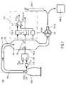
- FIG. 1 shows an exhaust system 100, in particular a primary gas dedusting system for convertible gas.
- hot primary gas escapes from an exhaust gas generator 200 in the form of a converter at its converter mouth 210.
- This primary gas is discharged via an exhaust duct 110 either to a chimney 300-1 or to a gas recovery plant 300-2.
- the exhaust duct 110 is connected to the converter mouth 210. More specifically, first, a cooling passage portion 112 of the exhaust passage 110 is directly downstream of the converter. In the flow direction, an exhaust gas scrubber section 114 adjoins the cooling channel section 112. Between the output 110-A of the exhaust passage 110 and the outlet of the scrubber section 114, a suction fan 130 is connected. The exhaust gas in the form of the primary gas flows through the exhaust duct in the direction of the arrow.
- a valve 120 is arranged, the opening position is typically varied by means of a control device 400 in accordance with a third control deviation such that the negative pressure of the exhaust gas is controlled at the converter mouth or in the chimney to a predetermined target negative pressure.
- the third control deviation represents the difference between the predetermined desired negative pressure and a detected actual negative pressure at the converter mouth 210 or in the chimney.
- the pressure tap is only on the converter mouth but not in the fireplace shown.
- the predetermined target negative pressure is designated by the reference symbol P Soll and the detected actual negative pressure is designated by the reference symbol P Ist . It is detected by means of a pressure sensor 410.
- a first control device 140 is provided to regulate the opening degree of the valve 120 to a predetermined desired opening degree by suitable variation of the rotational speed n of the suction fan 130.
- the first control device 140 can be operated without or in parallel to the third control device 400.
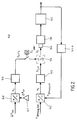
- FIG. 2 is first shown in the lower half of the design of the control device 140 according to a first embodiment.
- a first measuring member 141-V is provided for detecting the respective current opening degree of the valve 120.
- the thus determined actual opening degree V opening is Ist in a first setpoint / actual value comparator 142 with a predetermined target opening degree V opening target compared for the purpose of determining a first control difference e1.
- This first control difference e1 is supplied as a signal to a first controller 143, which provides a first actuating signal S1 for an actuator in the form of a speed sensor 144 for the exhaust fan in accordance with the received first control difference.
- the first actuating signal S1 represents a first rotational speed n1 for the exhaust fan.
- the variably set speed of the exhaust fan 130 has an immediate effect on the controlled system 145, in particular formed by the converter 200 and the exhaust passage 110 with the cooling channel section 112 and the exhaust scrubber section 114. Accordingly, the respective current speed also has an effect on the actual opening position of the valve 120, which is detected by means of the first measuring element 141-V.
- the second exemplary embodiment described below is suitable for the control device 140 according to the invention or for the operation of the exhaust system.
- This second exemplary embodiment provides that the above-mentioned pressure drop ⁇ p actual is detected above the valve 120 and compared with a predetermined desired pressure drop ⁇ p Soll .
- the second control deviation e 2 formed by subtracting these two variables is applied to a second controller 149.
- the pressure drop Dp is above the valve 120 is determined by the pressure at the inlet of the valve by means of a measuring member 146-E is detected and subtracted with the detected by a measuring element 146-A at the output of the valve pressure. The subtraction takes place in a subtractor 147.
- the second controller 149 provides at its output a second control signal S2, which represents a speed n2 for the suction fan 130 and its speed sensor 144.
- a maximum value selection stage 150 selects either the first control signal S1 or the second control signal S2 for switching to the speed sensor 144 from.
- the maximum value selection stage 150 in each case switches the actuating signal S1, S2 to the rotational speed generator 144, which represents the larger rotational speed n1, n2.
- the switch SW is closed; when the exhaust gas is delivered to a chimney, it is open.
- the desired pressure drop ⁇ p setpoint at the input of the second comparator 148 is predetermined in such a way that the atomization of the water injected into the exhaust gas scrubber or there into the primary gas is optimal.
Landscapes
- Engineering & Computer Science (AREA)
- Chemical & Material Sciences (AREA)
- Mechanical Engineering (AREA)
- General Engineering & Computer Science (AREA)
- Combustion & Propulsion (AREA)
- Manufacturing & Machinery (AREA)
- Materials Engineering (AREA)
- Metallurgy (AREA)
- Organic Chemistry (AREA)
- Environmental & Geological Engineering (AREA)
- Waste-Gas Treatment And Other Accessory Devices For Furnaces (AREA)
Description
- Die vorliegende Erfindung betrifft eine Abgasanlage mit einem Abgaskanal zum Aufnehmen von Abgas von einem Abgaserzeuger an seinem Eingang und zum Abgeben des Abgases an seinem Ausgang, mit einem Ventil in dem Abgaskanal, mit einem stromabwärts zu dem Ventil in dem Abgaskanal angeordneten Sauggebläse zum Fördern des Abgases innerhalb des Abgaskanals in Richtung Ausgang und mit einer Regelungseinrichtung. Die Erfindung betrifft auch ein Verfahren zum Betreib der Abgasanlage. Die vorliegende Erfindung findet vorzugsweise Anwendung bei einer Primärgas-Entstaubungsanlage für Konvertergas; sie ist jedoch nicht auf diese Anwendung beschränkt.
- Es wird auf den folgenden Stand der Technik hingewiesen, der in Stahlwerken zur Behandlung von Primärgas aus Konvertern derzeit üblich ist. Demnach wird das Primärgas, welches bei Betrieb des Konverters aus dessen Mund austritt, zunächst in einem Kühlkanal gekühlt und nachfolgend in einem Abgaswäscher mit Wasser bestäubt. Dem Abgaswäscher ist stromabwärts ein Absauggebläse nachgeschaltet zum Fördern des Primärgases entweder in einen Kamin oder in eine Gasrückgewinnungsanlage. In dem Abgaswäscher ist ein Ventil mit der Funktion einer Venturi-Kehle eingebaut; dort wird das Wasser in den Strom des Primärgases eingestäubt. Während seines Betriebes wird der Konverter typischerweise in verschiedenen Betriebszuständen gefahren; während dieser unterschiedlichen Betriebszustände können die Druckverhältnisse des Primärgases im Abgaskanal jeweils variieren. Um in all diesen verschiedenen Betriebszuständen und bei allen Druckverhältnissen jeweils eine ausreichende Saugleistung für das Primärgas im Abgaskanal zu haben, wird das Sauggebläse traditionell während des gesamten Blasbetriebs mit nahezu auf seiner maximalen Leistung, d. h. mit maximaler Drehzahl betrieben. Parallel dazu ist es üblich, den Öffnungsgrad des Ventils, d. h. der Venturi-Kehle, derart zu regeln, dass eine Regelabweichung zwischen einem Soll-Unterdruck und einem Ist-Unterdruck des Primärgases am Konvertermund oder im Kamin auf einen gewünschten Soll-Unterdruck eingeregelt wird.
- Der Dauerbetrieb des Gebläses auf konstant hoher Drehzahl hat den Nachteil, dass der Energieverbrauch des Gebläses und damit der Kostenaufwand für den Betrieb des Gebläses sehr hoch sind.
- Im Stand der Technik sind bereits zahlreiche Abgasanlagen und Verfahren zu deren Betrieb wie in
WO2009/086981 ,US2007/209653 ,US4067557 oderGB2016124 - So offenbaren die Druckschriften
DE 1 289 251 ,JP 11037455 A JP 56137015 A JP 11083006 A JP 2008180394 A - Darüber hinaus offenbart die deutsche Offenlegungsschrift
DE 3301668 A1 ein Regelverfahren für eine Sekundärentstaubungsanlage, wobei das Absauggebläse im Abgaskanal in seiner Drehzahl derart geregelt wird, dass der Druckverlust der Gesamtanlage auf einen vorgegebenen Sollwert für den Druckverlust der Gesamtanlage eingeregelt wird. - Schließlich ist auf der Homepage des Ingenieurbüros Peter Voss-Spilker Service erwähnt, dass die Europäische Union im Juni 2010 strengere Wirkungsgradgrenzwerte für Ventilatoren bei metallurgischen Anlagen festgelegt hat; siehe im Internet unter www.pvsservice.de.
- Der Erfindung liegt die Aufgabe zugrunde, für eine Abgasanlage und für ein Verfahren zu deren Betrieb eine alternative Regelung zur Regelung der Drehzahl des Sauggebläses im Abgaskanal der Abgasanlage vorzusehen, um Energie und Kosten einzusparen.
- Diese Aufgabe wird im Hinblick auf die Abgasanlage durch den Gegenstand des Anspruchs 1 gelöst. Demnach ist die Abgasanlage dadurch gekennzeichnet, dass die Regelungseinrichtung ausgebildet ist, den Öffnungsgrad des Ventils auf einen vorgegebenen Soll-Öffnungsgrad einzuregeln durch geeignete Variation der Drehzahl des Sauggebläses.
- Das Ventil mit geregelter Öffnungsstellung im Abgaswäscherabschnitt des Abgaskanals bildet eine geregelte Venturi-Kehle zum Einstäuben von Wasser in das Primärgas im Abgaswäscherabschnitt des Abgaskanals.
- Der für das Ventil vorgegebene Soll-Öffnungsgrad wird empirisch bzw. auf Basis von Erfahrungswerten ermittelt und vorgegeben. Die beanspruchte Regelung bewirkt vorteilhafterweise, dass das Sauggebläse 130 nicht permanent bei maximaler Leistung bzw. bei maximaler Drehzahl betrieben werden muss, sondern dass dessen Drehzahl bedarfsabhängig gesenkt und damit auch der Bedarf an elektrischer Energie sowie die Kosten für den Betrieb des Gebläses deutlich reduziert werden können.
- Ein erstes Ausführungsbeispiel für die beanspruchte Regelungseinrichtung ist in Anspruch 2 beschrieben. Dieses erste Ausführungsbeispiel zeichnet sich dadurch aus, dass die Drehzahl für das Sauggebläse nach Maßgabe einer ersten Regeldifferenz zwischen dem vorgegebenen Soll-Öffnungsgrad und einem gemessenen Ist-Öffnungsgrad des Ventils variiert wird. Ziel ist es dabei, die erste Regeldifferenz möglichst zu Null zu machen und auf diese Weise den Öffnungsgrad des Ventils auf dem vorgegebenen Soll-Öffnungsgrad zu halten. Anspruch 3 beschreibt eine dazu alternative Ausgestaltung der Regelungseinrichtung, wonach vorgesehen ist, dass die Drehzahl für das Sauggebläse nach Maßgabe einer zweiten Regelabweichung zwischen einem vorgegebenen Soll-Druckabfall und einem tatsächlich gemessenen Ist-Druckabfall über dem Ventil variiert wird. Ziel ist es dabei, die zweite Regeldifferenz möglichst zu Null zu machen und auf diese Weise den Druckabfall über dem Ventil auf den vorgegebenen Soll-Druckabfall einzuregeln.
- Die Entscheidung, ob die Drehzahl für das Sauggebläse nach Maßgabe der ersten oder der zweiten Regelabweichung variiert wird, hängt grundsätzlich davon ab, welche Alternative die größere Drehzahl für das Sauggebläse bereitstellt. Zu diesem Zweck weist die erfindungsgemäße Regelungseinrichtung eine Maximalwert-Auswahlstufe auf, welche jeweils dasjenige Stellsignal auf einen Drehzahlgeber als Stellglied für das Sauggebläse durchschaltet, welches die größere Drehzahl für das Sauggebläse repräsentiert.
- Vorteilhafterweise und besonders bevorzugt wird die Erfindung in einer Abgasanlage in einem Stahlwerk mit Konverter betrieben. Bei dem Abgaserzeuger handelt es sich dann um einen Konverter, dessen Konvertermund an den Eingang des Abgaskanals angeschlossen ist. Bei dem Abgas handelt es sich dann um Primärgas, welches bei Betrieb des Konverters aus dessen Konvertermund austritt. Der Abgaskanal weist dann einen Kühlkanalabschnitt auf zum Kühlen des Primärgases, wobei sich der Kühlkanalabschnitt unmittelbar an den Konvertermund anschließt. Zwischen dem Ausgang des Kühlkanalabschnitts und dem Sauggebläse ist ein Abgaswäscherabschnitt im Abgaskanal vorgesehen. In dem Abgaswäscherabschnitt ist das Ventil angeordnet, dessen Öffnungsstellung mit der erfindungsgemäßen Regelungseinrichtung auf eine Soll-Öffnungsstellung eingeregelt wird. Stromabwärts des Absauggebläses wird das Primärgas entweder an einen Kamin oder an eine Gasrückgewinnungsanlage abgegeben.
- Die erfindungsgemäßen Regelungen erfolgen grundsätzlich nur, wenn der Konverter im Blasbetrieb betrieben wird, d. h. wenn Sauerstoff in den Konverter eingeblasen wird.
- Die gemäß dem oben beschriebenen zweiten Ausführungsbeispiel beschriebene alternative Bereitstellung eines Stellsignals für den Drehzahlgeber für das Absauggebläse nach Maßgabe der zweiten Regeldifferenz ist überhaupt nur dann vorgesehen, wenn das Abgas am Ausgang des Abgaskanals an die Gasrückgewinnungsanlage abgegeben wird. In allen anderen Fällen, insbesondere wenn das Primärgas an den Kamin abgegeben wird, wird das zweite Steuersignal S2 nicht für die Maximalwert-Auswahlstufe bereitgestellt; diese schaltet dann automatisch das erste Stellsignal auf den Drehzahlgeber 144 durch.
- Die oben erwähnte Aufgabe der Erfindung wird weiterhin durch ein beanspruchtes Verfahren zum Betreiben der zuvor beschriebenen Abgasanlage gelöst. Das gilt insbesondere für den Betrieb der Abgasanlage in einem Stahlwerk mit Konverterbetrieb, wie ebenfalls oben beschrieben.
- Ergänzend bzw. parallel zu dem bisher beschriebenen Betrieb der Regelungseinrichtung gemäß dem ersten oder zweiten Verfahren kann im Sinne einer Kaskadenregelung vorgesehen sein, dass zusätzlich die Öffnungsstellung des Ventils im Abgaswäscherabschnitt nach Maßgabe einer dritten Regelabweichung variabel eingestellt werden kann, um den Unterdruck des Abgases am Konvertermund oder im Kamin auf einen vorgegebenen Soll-Unterdruck einzuregeln. Die dritte Regelabweichung repräsentiert dann die Differenz zwischen dem vorgegebenen Soll-Unterdruck und einem erfassten Ist-Unterdruck des Abgases am Konvertermund oder im Kamin.
- Der Beschreibung sind zwei Figuren beigefügt, wobei
- Figur 1
- eine Abgasanlage mit einer erfindungsgemäßen Regelungseinrichtung zur Regelung der Drehzahl eines Absauggebläses im Abgaskanal;
und - Figur 2
- ein Blockschaltbild zur Erläuterung der Funktionsweise der erfindungsgemäßen Regelungseinrichtung
zeigt. - Die Erfindung wird nachfolgend unter Bezugnahme auf die genannten Figuren in Form von Ausführungsbespielen detailliert beschrieben.
-
Figur 1 zeigt eine Abgasanlage 100, insbesondere eine Primärgas-Entstaubungsanlage für Konvertgas. Bei Betrieb entweicht aus einem Abgaserzeuger 200 in Form eines Konverters an dessen Konvertermund 210 heißes Primärgas. Dieses Primärgas wird über einen Abgaskanal 110 entweder an einen Kamin 300-1 oder an eine Gasrückgewinnungsanlage 300-2 abgegeben. An seinem Eingang 110-E ist der Abgaskanal 110 an den Konvertermund 210 angeschlossen. Genauer gesagt ist zunächst ein Kühlkanalabschnitt 112 des Abgaskanals 110 dem Konverter direkt nachgeschaltet. In Strömungsrichtung schließt sich an den Kühlkanalabschnitt 112 ein Abgaswäscherabschnitt 114 an. Zwischen den Ausgang 110-A des Abgaskanals 110 und den Ausgang des Abgaswäscherabschnittes 114 ist ein Sauggebläse 130 geschaltet. Das Abgas in Form des Primärgases durchströmt den Abgaskanal in Pfeilrichtung. - Innerhalb des Abgaswäscherabschnitts 114 ist ein Ventil 120 angeordnet, dessen Öffnungsstellung typischerweise mit Hilfe einer Regelungseinrichtung 400 nach Maßgabe einer dritten Regelabweichung derart variiert wird, dass der Unterdruck des Abgases am Konvertermund oder im Kamin auf einen vorgegebenen Soll-Unterdruck geregelt wird. Die dritte Regelabweichung repräsentiert die Differenz zwischen dem vorgegeben Soll-Unterdruck und einem erfassten Ist-Unterdruck am Konvertermund 210 oder im Kamin. Um die
Figur 1 nicht unnötig zu überfrachten, ist der Druckabgriff lediglich am Konvertermund nicht aber im Kamin gezeigt. Der vorgegebene Soll-Unterdruck ist mit dem Bezugszeichen PSoll bezeichnet und der erfasste Ist-Unterdruck ist mit dem Bezugszeichen PIst bezeichnet. Er wird mit Hilfe eines Drucksensors 410 erfasst. - Erfindungsgemäß ist eine erste Regelungseinrichtung 140 vorgesehen, um den Öffnungsgrad des Ventils 120 auf einen vorgegebenen Soll-Öffnungsgrad einzuregeln durch geeignete Variation der Drehzahl n des Sauggebläses 130. Die erste Regelungseinrichtung 140 kann ohne oder parallel zu der dritten Regelungseinrichtung 400 betrieben werden.
- Der Aufbau und die Funktionsweise dieser ersten Regelungseinreichung 140 wird nachfolgend unter Bezugnahme auf
Figur 2 näher erläutert. - In
Figur 2 ist zunächst in der unteren Hälfte die Ausbildung der Regelungseinrichtung 140 gemäß einem ersten Ausführungsbeispiel gezeigt. Demnach ist ein erstes Messglied 141-V vorgesehen zum Erfassen des jeweils aktuellen Öffnungsgrades des Ventils 120. Der so ermittelte Ist-Öffnungsgrad VÖffnung Ist wird in einem ersten Soll-/Ist-Wert-Vergleicher 142 mit einem vorgegebenen Soll-Öffnungsgrad VÖffnung Soll verglichen zwecks Ermittlung einer ersten Regeldifferenz e1. Diese erste Regeldifferenz e1 wird als Signal einem ersten Regler 143 zugeführt, welcher nach Maßgabe der empfangenen ersten Regeldifferenz ein erstes Stellsignal S1 für ein Stellglied in Form eines Drehzahlgebers 144 für das Absauggebläse bereitstellt. Das erste Stellsignal S1 repräsentiert eine erste Drehzahl n1 für das Absauggebläse. - Die variabel eingestellte Drehzahl des Absauggebläses 130 hat unmittelbare Auswirkung auf die Regelstrecke 145, insbesondere gebildet durch den Konverter 200 und den Abgaskanal 110 mit dem Kühlkanalabschnitt 112 und dem Abgaswäscherabschnitt 114. Dementsprechend hat die jeweils aktuelle Drehzahl auch Auswirkung auf die tatsächliche Öffnungsstellung des Ventils 120, welche mit Hilfe des ersten Messgliedes 141-V erfasst wird.
- Die am ersten Soll-/Ist-Wert-Vergleicher 142 vorgegebene Soll-Öffnungsstellung für das Ventil 120 wird für die bevorzugte Anwendung zur Primärgas-Entstaubung für Konvertergas zu 30 % ± 5 %, bezogen auf die maximale Offenstellung von 100 %, eingeregelt bzw. vorgegeben. Diese Öffnungsstellung von ± 30 % bietet die beiden folgenden Vorteile:
- 1. dann ist der Druckabfall, d. h. die Differenz zwischen Druck am Ausgang und Druck am Eingang des Ventils minimal; dies ist vorteilhaft für das Abbrennen des Primärgases nach Verlassen des Abgaskanals 110.
- 2. denn liegt der Arbeitspunkt des Ventils vorteilhafterweise in einem näherungsweise linearen Bereich der Kennlinie des Ventils.
- Wenn das Abgas nicht an einen Kamin, sondern an eine Gasrückgewinnungsanlage geleitet wird, bietet sich das nachfolgend beschriebene zweite Ausführungsbeispiel für die erfindungsgemäße Regelungseinrichtung 140 bzw. für den Betrieb der Abgasanlage an.
- Dieses zweite Ausführungsbeispiel sieht vor, dass der oben bereits erwähnte Druckabfall ΔpIst über dem Ventil 120 erfasst und mit einem vorgegebenen Soll-Druckabfall ΔpSoll verglichen wird. Die durch Subtraktion dieser beiden Größen gebildete zweite Regelabweichung e2 wird auf einen zweiten Regler 149 gegeben. Der Druckabfall ΔpIst über dem Ventil 120 wird ermittelt, indem der Druck am Eingang des Ventils mit Hilfe eines Messglieds 146-E erfasst wird und mit dem von einem Messglied 146-A am Ausgang des Ventils erfassten Druck subtrahiert wird. Die Subtraktion erfolgt in einem Differenzbildner 147.
- Der zweite Regler 149 stellt an seinem Ausgang ein zweites Regelsignal S2 bereit, welches eine Drehzahl n2 für das Sauggebläse 130 bzw. dessen Drehzahlgeber 144 repräsentiert. Gemäß dem zweiten Ausführungsbeispiel wählt dann eine Maximalwert-Auswahlstufe 150 entweder das erste Stellsignal S1 oder das zweite Stellsignal S2 zur Durchschaltung auf den Drehzahlgeber 144 aus. Die Maximalwert-Auswahlstufe 150 schaltet jeweils dasjenige Stellsignal S1, S2 auf den Drehzahlgeber 144 durch, welches die größere Drehzahl n1, n2 repräsentiert. Wenn das Abgas an die Gasrückgewinnungsanlage abgegeben wird, ist der Schalter SW geschlossen; wenn das Abgas an einen Kamin abgegeben wird, ist er geöffnet. Der Soll-Druckabfall ΔpSoll am Eingang des zweiten Vergleichers 148 wird derart vorgegeben, dass die Zerstäubung des in den Abgaswäscher bzw. dort in das Primärgas eingedüsten Wassers optimal ist.
-
- 100
- Abgasanlage
- 110
- Abgaskanal
- 110-E
- Eingang des Abgaskanals
- 110-A
- Ausgang des Abgaskanals
- 112
- Kühlkanalabschnitt
- 120
- Ventil
- 130
- Sauggebläse
- 140
- Regelungseinrichtung
- 141-V
- Erstes Messglied
- 142
- Erster Vergleicher
- 143
- Erster Regler
- 144
- Stellglied in Form eines Drehzahlreglers für das Absauggebläse
- 145
- Regelstrecke
- 146-E
- Zweites Messglied zum Erfassen des Drucks am Eingang des Ventils
- 146-A
- Drittes Messglied zum Erfassen des Drucks am Ausgang des Ventils
- 147
- Differenzbildner
- 148
- Zweiter Vergleicher
- 149
- Zweiter Regler
- 150
- Maximalwert-Auswahlstufe
- 200
- Abgaserzeuger, insbesondere Konverter
- 210
- Konvertermund
- 300-1
- Kamin
- 300-2
- Gasrückgewinnungsanlage
- S1
- Erstes Stellsignal
- S2
- Zweites Stellsignal
- e1
- Erste Regeldifferenz
- e2
- Zweite Regeldifferenz
- VÖffnung Soll
- Vorgegebener Soll-Öffnungsgrad des Ventils
- VÖffnung Ist
- Erfasster bzw. gemessener Ist-Öffnungsgrad des Ventils
- ΔpSoll
- Vorgegebener Soll-Druckabfall über dem Ventil
- ΔpIst
- Gemessener Ist-Druckabfall über dem Ventil
- n1
- Erste Drehzahl für das Sauggebläse
- n2
- Zweite Drehzahl für das Sauggebläse
Claims (11)
- Abgasanlage (100) mit
einem Abgaskanal (110) zum Aufnehmen von Abgas von einem Abgaserzeuger (200) an seinem Eingang (110-E) und zum Abgeben des Abgases an seinem Ausgang (110-A),
einem Ventil (120) in dem Abgaskanal,
einem stromabwärts zu dem Ventil (120) in dem Abgaskanal (110) angeordneten Sauggebläse (130) zum Fördern des Abgases innerhalb des Abgaskanals in Richtung Ausgang (110-A), und
einer Regeleinrichtung (140),
dadurch gekennzeichnet, dass
die Regelungseinrichtung (140) aufweist,
ein erstes Messglied (141-V) zum Erfassen des jeweils aktuellen Ist-Öffnungsgrades des Ventils (120),
einen ersten Soll-/Ist-Wert-Vergleicher (142) zum Ermitteln einer ersten Regeldifferenz e1 als Differenz zwischen dem vorgegebenen Soll-Öffnungsgrad (VÖffnung Soll) und dem gemessenen Ist-Öffnungsgrad (VÖffnung Ist) des Ventils (120),
einen ersten Regler (143) zum Ausgeben eines ersten Stellsignals (S1) nach Maßgabe der empfangenen ersten Regeldifferenz e1 zwischen dem vorgegebenen Soll-Öffnungsgrad (VÖffnung Soll) und einem gemessenen Ist-Öffnungsgrad (VÖffnung Ist) des Ventils (120), wobei das ersten Stellsignal (S1) eine erste Drehzahl n1 für das Abgasgebläse (130) repräsentiert, und ein Stellglied (144) in Form eines Drehzahlgebers für das Absauggebläse (130) zum Einstellen und gegebenenfalls Variieren der Drehzahl im Ansprechen auf das empfangene erste Stellsignal (S1),
wodurch die Regeleinrichtung (140) ausgebildet ist, den Öffnungsgrad des Ventils (120) auf einen vorgegebenen Soll-Öffnungsgrad (VÖffnung Soll) einzure-geln durch geeignete Variation der Drehzahl des Sauggebläses (130). - Abgasanlage (100) nach Anspruch 1,
dadurch gekennzeichnet, dass
die Regeleinrichtung (140) zusätzlich folgende Erweiterungen aufweist:ein zweites und ein drittes Messglied (146-E, 146-A) sowie einen Vergleicher (147) zum Erfassen des Ist-Druckabfalls ΔpIst über dem Ventil (120), einen zweiten Soll-/Ist-Wert-Vergleicher (148) zum Ermitteln einer zweiten Regeldifferenz e2 als Differenz zwischen einem vorgegebenen Soll-Druckabfall (ΔpSoll) und dem gemessenen Ist-Druckabfall (ΔpIst) über dem Ventil (120),einen zweiten Regler (149) zum Ausgeben eines zweiten Stellsignals (S2) nach Maßgabe der empfangenen zweiten Regelabweichung e2 zwischen dem vorgegebenen Soll-Druckabfall (ΔpSoll) und dem gemessenen Ist-Druckabfall (ΔpIst) über dem Ventil (120),wobei das zweite Stellsignal (S2) eine zweite Drehzahl (n2) für das Abgasgebläse (130) repräsentiert, undeine Maximalwert-Auswahlstufe (150) zum Aufschalten des ersten Stellsignals (S1) auf den Drehzahlgeber (144), wenn die erste Drehzahl (n1) größer als die zweite Drehzahl (n2) oder zum Aufschalten des zweiten Stellsignals (S2) auf den Drehzahlgeber (144), wenn die zweite Drehzahl (n2) größer als die erste Drehzahl (n1) ist. - Abgasanlage (100) nach einem der vorangegangenen Ansprüche,
dadurch gekennzeichnet, dass
es sich bei dem Abgaserzeuger (200) um einen Konverter in einem Stahlwerk handelt, dessen Konvertermund (210) an den Eingang (110-E) des Abgaskanals (110) angeschlossen ist,
dass es sich bei dem Abgas um das Primärgas handelt, welches bei Betrieb I des Konverters aus dessen Kovertermund austritt,
dass der Abgaskanal (110) einen Kühlkanalabschnitt (112) aufweist, der sich an den Konvertermund (210) anschließt, und einen Abgaswäscherabschnitt (114) aufweist, welcher stromabwärts dem Kühlkanal nachgeschaltet und dem Sauggebläse (130) vorgeschaltet ist, wobei das Ventil (120) in dem Abgaswäscherabschnitt (114) angeordnet ist, und dass das Abgas am Ausgang (110-A) des Abgaskanals entweder an einen Kamin (300-1) oder an eine Gasrückgewinnungsanlage (300-2) abgegeben wird. - Abgasanlage (100) nach einem der Ansprüche 2 und 3,
dadurch gekennzeichnet, dass
die Erweiterung der Regelungseinrichtung (140) nach Anspruch 3 lediglich dann vorgesehen ist, wenn das Abgas am Ausgang (110-A) des Abgaskanals an die Gasrückgewinnungsanlage (300-2) abgegeben wird. - Verfahren zum Betreiben einer Abgasanlage (100), wobei die Abgasanlage aufweist einen Abgaskanal (110) zum Aufnehmen von Abgas von einem Abgaserzeuger (200) an seinem Eingang (110-E) und zum Abgeben des Abgases an seinem Ausgang (110-A), ein Ventil (120) in dem Abgaskanal (110, 114), ein stromabwärts zu dem Ventil (120) in dem Abgaskanal angeordnetes Sauggebläse (130) zum Fördern des Abgases innerhalb des Abgaskanals in Richtung Ausgang, und eine Regeleinrichtung (140),
gekennzeichnet durch folgende Schritte:Regeln des Öffnungsgrades des Ventils (120) auf einen vorgegebenen Soll-Öffnungsgrad (VÖffnung Soll) durch geeignete Variation der Drehzahl des Sauggebläses (130). - Verfahren nach Anspruch 5,
gekennzeichnet durch die folgenden Schritte:Erfassen des jeweils aktuellen Ist-Öffnungsgrades des Ventils (VÖffnung Ist), Ermitteln einer ersten Regeldifferenz e1 als Differenz zwischen dem vorgegebenen Soll-Öffnungsgrad und dem gemessenen Ist-Öffnungsgrad des Ventils,Erzeugen eines ersten Stellsignals (S1) nach Maßgabe der ersten Regeldifferenz e1 zwischen dem vorgegebenen Soll-Öffnungsgrad und einem gemessenen Ist-Öffnungsgrad des Ventils (120), wobei das erste Stellsignal (S1) eine erste Drehzahl (n1) für das Abgasgebläse repräsentiert, undEinstellen und gegebenenfalls Variieren der ersten Drehzahl (n1) im Ansprechen auf das empfangene erste Stellsignal (S1). - Verfahren nach Anspruch 6,
weiterhin gekennzeichnet durch folgende Schritte:Erfassen des Ist-Druckabfalls Δp über dem Ventil (120),Ermitteln einer zweiten Regeldifferenz e2 als Differenz zwischen einem vorgegebenen Soll-Druckabfall (ΔpSoll) und dem gemessenen Ist-Druckabfall (ΔpIst) über dem Ventil (120),Erzeugen eines zweiten Stellsignals (S2) nach Maßgabe der zweiten Regelabweichung e2 zwischen dem vorgegebenen Soll-Druckabfall (ΔpSoll) und dem gemessenen Ist-Druckabfall (ΔpIst) über dem Ventil (120), wobei das zweite Stellsignal (S2) eine zweite Drehzahl (n2) für das Abgasgebläse repräsentiert, undAufschalten des ersten Stellsignals (S1) auf den Drehzahlgeber (144), wenn die erste Drehzahl (n1) größer als die zweite Drehzahl (n2) oder zum Aufschalten des zweiten Stellsignals (S2) auf den Drehzahlgeber, wenn die erste Drehzahl (n1) kleiner als die zweite Drehzahl (n2) ist. - Verfahren nach Anspruch 7,
dadurch gekennzeichnet, dass
die Ermittlung der zweiten Regeldifferenz (e2) und die Bereitstellung des zweiten Stellsignals (S2) zur Auswahl neben dem ersten Stellsignal (S1) nur dann erfolgt, wenn das Abgas am Ausgang des Abgaskanals an eine Gasrückgewinnungsanlage (300-2) abgegeben wird. - Verfahren nach einem der Ansprüche 5 bis 8,
dadurch gekennzeichnet, dass
es sich bei dem Abgaserzeuger (200) um einen Konverter in einem Stahlwerk handelt, dessen Konvertermund (210) an den Eingang (110-E) des Abgaskanals (110) angeschlossen ist,
dass es sich bei dem Abgas um das Primärgas handelt, welches bei Betrieb des Konverters aus dessen Kovertermund austritt,
dass der Abgaskanal (110) einen Kühlkanalabschnitt (112) aufweist, der sich an den Konvertermund (210) anschließt, und einen Abgaswäscherabschnitt (114) aufweist, welcher stromabwärts dem Kühlkanal nachgeschaltet und dem Sauggebläse (130) vorgeschaltet ist, wobei ein Ventil (120) in dem Abgaswäscherabschnitt (114) angeordnet ist, und dort als geregelte Venturi-Kehle betrieben wird zum Einstäuben von Wasser in das Abgas in dem Abgaswäscherabschnitt (114) des Abgaskanals (110) und dass das Abgas am Ausgang (110-A) des Abgaskanals entweder an einen Kamin (300-1) oder an eine Gasrückgewinnungsanlage (300-2) abgegeben wird. - Verfahren nach Anspruch 9,
dadurch gekennzeichnet, dass
die Variation der Öffnungsstellung des Ventils (120) nach Maßgabe einer dritten Regelabweichung erfolgt, welche die Differenz zwischen einem vorgegebenen Soll-Unterdruck und einem erfassten Ist-Unterdruck am Konvertermund (210) oder im Kamin repräsentiert und wobei durch die Variation der Öffnungsstellung des Ventils angestrebt wird, dass die dritte Regelabweichung möglichst zu Null wird. - Verfahren nach einem der Ansprüche 5 bis 10,
dadurch gekennzeichnet, dass
sämtliche Verfahrensschritte nur erfolgen, während der Abgaserzeuger (200) in Form des Konverters im Blasbetrieb betrieben wird.
Applications Claiming Priority (2)
| Application Number | Priority Date | Filing Date | Title |
|---|---|---|---|
| DE102012224510.3A DE102012224510A1 (de) | 2012-12-28 | 2012-12-28 | Abgasanlage und Verfahren zu deren Betrieb |
| PCT/EP2013/077962 WO2014102263A1 (de) | 2012-12-28 | 2013-12-23 | Abgasanlage mit regeleinrichtung und verfahren zu deren betrieb |
Publications (2)
| Publication Number | Publication Date |
|---|---|
| EP2938954A1 EP2938954A1 (de) | 2015-11-04 |
| EP2938954B1 true EP2938954B1 (de) | 2016-09-14 |
Family
ID=49958430
Family Applications (1)
| Application Number | Title | Priority Date | Filing Date |
|---|---|---|---|
| EP13821488.7A Active EP2938954B1 (de) | 2012-12-28 | 2013-12-23 | Abgasanlage mit regeleinrichtung und verfahren zu deren betrieb |
Country Status (3)
| Country | Link |
|---|---|
| EP (1) | EP2938954B1 (de) |
| DE (1) | DE102012224510A1 (de) |
| WO (1) | WO2014102263A1 (de) |
Families Citing this family (1)
| Publication number | Priority date | Publication date | Assignee | Title |
|---|---|---|---|---|
| CN116464659B (zh) * | 2023-05-10 | 2025-09-02 | 阳春新钢铁有限责任公司 | 一种用于炼钢除尘器自动升降速控制方法 |
Family Cites Families (10)
| Publication number | Priority date | Publication date | Assignee | Title |
|---|---|---|---|---|
| DE1289251B (de) | 1963-05-27 | 1969-02-13 | Siemens Ag | Regeleinrichtung fuer die beiden Abgasgeblaese eines mit einem Zementdrehrohrofen zusammenarbeitenden Vorwaermersystems |
| US4067557A (en) * | 1976-07-02 | 1978-01-10 | Kawasaki Jukogyo Kabushiki Kaisha | System for changing over of blast furnace top pressure control |
| JPS56137015A (en) | 1980-03-26 | 1981-10-26 | Toshiba Corp | Blower of furnace |
| US4531973A (en) * | 1980-04-08 | 1985-07-30 | Nixon Ivor G | Metallurgical processes |
| DE3301668A1 (de) | 1983-01-20 | 1984-07-26 | Metallgesellschaft Ag, 6000 Frankfurt | Regelverfahren fuer eine entstaubungsanlage |
| JPH1137455A (ja) | 1997-07-14 | 1999-02-12 | Daido Steel Co Ltd | 加熱炉における排気ファンの回転数制御方法 |
| JP3174538B2 (ja) | 1997-09-03 | 2001-06-11 | 日本碍子株式会社 | 燃焼炉の炉内圧制御方法 |
| US20070209653A1 (en) * | 2003-03-06 | 2007-09-13 | Exhausto, Inc. | Pressure Controller for a Mechanical Draft System |
| JP5007569B2 (ja) | 2007-01-23 | 2012-08-22 | 大同特殊鋼株式会社 | 粉塵排気装置の制御方法 |
| DK176904B1 (da) * | 2008-01-05 | 2010-04-12 | Smidth As F L | Indretning og fremgangsmåde til afkøling af ovnrøggas i et ovn-bypass |
-
2012
- 2012-12-28 DE DE102012224510.3A patent/DE102012224510A1/de not_active Withdrawn
-
2013
- 2013-12-23 WO PCT/EP2013/077962 patent/WO2014102263A1/de not_active Ceased
- 2013-12-23 EP EP13821488.7A patent/EP2938954B1/de active Active
Also Published As
| Publication number | Publication date |
|---|---|
| EP2938954A1 (de) | 2015-11-04 |
| DE102012224510A1 (de) | 2014-07-03 |
| WO2014102263A1 (de) | 2014-07-03 |
Similar Documents
| Publication | Publication Date | Title |
|---|---|---|
| DE3312704C2 (de) | Trocknungsvorrichtung für eine Druckmaschine, mit Abgasrückführung von einer Oxidations- und Vorheizeinrichtung | |
| EP2844937B1 (de) | Anlage mit einer prozesskammer für werkstücke | |
| DE3121860C2 (de) | Verfahren zum Vorwärmen von Stahlschrott mittels des Abgases aus einem Stahlerzeugungs-Elektroofen | |
| DE102006008712B4 (de) | Brennstoffgas-Kalorie-Regelungsvorrichtung und Gasturbinensystem | |
| DE3017761C2 (de) | Anlage zur Energiegewinnung aus Hochofen-Gichtgas | |
| EP4479162A1 (de) | VERFAHREN UND VORRICHTUNG ZUR BEHANDLUNG VON PRIMÄRGAS AUS EINEM METALLURGISCHEN GEFÄß | |
| EP2938954A1 (de) | Abgasanlage mit regeleinrichtung und verfahren zu deren betrieb | |
| DE102009029118A1 (de) | Strahlheizvorrichtung | |
| EP1934528B1 (de) | Verfahren und vorrichtung zur überwachung sich bildender ablagerungen von feststoffteilchen, insbesondere in einer brennstoffleitung sowie in den brennstoffventilen einer gasturbine | |
| WO2019086511A1 (de) | Verfahren und anlage zur thermischen behandlung eines lithiumerzes | |
| DE69803157T2 (de) | Ofen mit einer schnellen Kühlung für Metallbänder | |
| EP0049328A1 (de) | Vorrichtung zur Ausnutzung der Wärme im Abgas von mehreren Prozessbereichen | |
| DE102017006416A1 (de) | Industrieofen | |
| DE102008044709A1 (de) | Verfahren und Vorrichtung zum Fördern von Verbrennungsrückständen | |
| AT413602B (de) | Vorrichtung und verfahren zum trocknen einer substanz, insbesondere klärschlamm | |
| DE3345202A1 (de) | Vorrichtung zur herabsetzung der taupunkttemperatur von abgasen | |
| DE19712771C2 (de) | Verfahren und Anordnung zur automatischen Verbrennungsregelung in Heizkesseln | |
| DE10314041A1 (de) | Verfahren und Vorrichtung zur Anpassung der Parameter des Heissgases eines Heissgaserzeugers mit nachgeschaltetem technologischem Prozess | |
| DE102010006577A1 (de) | Vorrichtung und Verfahren zur Wärmebehandlung von bahnförmigen Warenbahnen | |
| DE246812C (de) | ||
| EP3168549B1 (de) | Verfahren zum betrieb einer heizungsanlage | |
| EP3359898A1 (de) | Vorrichtung zur temperierung von gegenständen sowie verfahren zur steuerung einer vorrichtung zur temperierung von gegenständen | |
| WO2026073770A1 (de) | Messung des falschlufteintrages in eine oxyfuel anlage | |
| EP2416068A2 (de) | Vorrichtung und Verfahren zum Nachverbrennen von heißem Material auf einem Förderer | |
| WO2025061306A1 (de) | Rösteranordnung für pflanzliches schüttgut sowie verfahren zum betreiben einer rösteranordnung |
Legal Events
| Date | Code | Title | Description |
|---|---|---|---|
| PUAI | Public reference made under article 153(3) epc to a published international application that has entered the european phase |
Free format text: ORIGINAL CODE: 0009012 |
|
| 17P | Request for examination filed |
Effective date: 20150728 |
|
| AK | Designated contracting states |
Kind code of ref document: A1 Designated state(s): AL AT BE BG CH CY CZ DE DK EE ES FI FR GB GR HR HU IE IS IT LI LT LU LV MC MK MT NL NO PL PT RO RS SE SI SK SM TR |
|
| AX | Request for extension of the european patent |
Extension state: BA ME |
|
| REG | Reference to a national code |
Ref country code: DE Ref legal event code: R079 Ref document number: 502013004637 Country of ref document: DE Free format text: PREVIOUS MAIN CLASS: F27D0019000000 Ipc: C21C0005400000 |
|
| DAX | Request for extension of the european patent (deleted) | ||
| GRAP | Despatch of communication of intention to grant a patent |
Free format text: ORIGINAL CODE: EPIDOSNIGR1 |
|
| RIC1 | Information provided on ipc code assigned before grant |
Ipc: C21B 7/00 20060101ALI20160307BHEP Ipc: F23L 17/00 20060101ALI20160307BHEP Ipc: F23N 3/08 20060101ALI20160307BHEP Ipc: C21C 5/40 20060101AFI20160307BHEP Ipc: F27D 19/00 20060101ALI20160307BHEP |
|
| INTG | Intention to grant announced |
Effective date: 20160408 |
|
| GRAS | Grant fee paid |
Free format text: ORIGINAL CODE: EPIDOSNIGR3 |
|
| GRAA | (expected) grant |
Free format text: ORIGINAL CODE: 0009210 |
|
| AK | Designated contracting states |
Kind code of ref document: B1 Designated state(s): AL AT BE BG CH CY CZ DE DK EE ES FI FR GB GR HR HU IE IS IT LI LT LU LV MC MK MT NL NO PL PT RO RS SE SI SK SM TR |
|
| REG | Reference to a national code |
Ref country code: GB Ref legal event code: FG4D Free format text: NOT ENGLISH |
|
| REG | Reference to a national code |
Ref country code: CH Ref legal event code: EP |
|
| REG | Reference to a national code |
Ref country code: IE Ref legal event code: FG4D Free format text: LANGUAGE OF EP DOCUMENT: GERMAN |
|
| REG | Reference to a national code |
Ref country code: AT Ref legal event code: REF Ref document number: 829063 Country of ref document: AT Kind code of ref document: T Effective date: 20161015 |
|
| REG | Reference to a national code |
Ref country code: DE Ref legal event code: R096 Ref document number: 502013004637 Country of ref document: DE |
|
| REG | Reference to a national code |
Ref country code: LT Ref legal event code: MG4D |
|
| REG | Reference to a national code |
Ref country code: NL Ref legal event code: MP Effective date: 20160914 |
|
| PG25 | Lapsed in a contracting state [announced via postgrant information from national office to epo] |
Ref country code: HR Free format text: LAPSE BECAUSE OF FAILURE TO SUBMIT A TRANSLATION OF THE DESCRIPTION OR TO PAY THE FEE WITHIN THE PRESCRIBED TIME-LIMIT Effective date: 20160914 Ref country code: FI Free format text: LAPSE BECAUSE OF FAILURE TO SUBMIT A TRANSLATION OF THE DESCRIPTION OR TO PAY THE FEE WITHIN THE PRESCRIBED TIME-LIMIT Effective date: 20160914 Ref country code: NO Free format text: LAPSE BECAUSE OF FAILURE TO SUBMIT A TRANSLATION OF THE DESCRIPTION OR TO PAY THE FEE WITHIN THE PRESCRIBED TIME-LIMIT Effective date: 20161214 Ref country code: LT Free format text: LAPSE BECAUSE OF FAILURE TO SUBMIT A TRANSLATION OF THE DESCRIPTION OR TO PAY THE FEE WITHIN THE PRESCRIBED TIME-LIMIT Effective date: 20160914 Ref country code: RS Free format text: LAPSE BECAUSE OF FAILURE TO SUBMIT A TRANSLATION OF THE DESCRIPTION OR TO PAY THE FEE WITHIN THE PRESCRIBED TIME-LIMIT Effective date: 20160914 |
|
| PG25 | Lapsed in a contracting state [announced via postgrant information from national office to epo] |
Ref country code: NL Free format text: LAPSE BECAUSE OF FAILURE TO SUBMIT A TRANSLATION OF THE DESCRIPTION OR TO PAY THE FEE WITHIN THE PRESCRIBED TIME-LIMIT Effective date: 20160914 Ref country code: LV Free format text: LAPSE BECAUSE OF FAILURE TO SUBMIT A TRANSLATION OF THE DESCRIPTION OR TO PAY THE FEE WITHIN THE PRESCRIBED TIME-LIMIT Effective date: 20160914 Ref country code: SE Free format text: LAPSE BECAUSE OF FAILURE TO SUBMIT A TRANSLATION OF THE DESCRIPTION OR TO PAY THE FEE WITHIN THE PRESCRIBED TIME-LIMIT Effective date: 20160914 Ref country code: GR Free format text: LAPSE BECAUSE OF FAILURE TO SUBMIT A TRANSLATION OF THE DESCRIPTION OR TO PAY THE FEE WITHIN THE PRESCRIBED TIME-LIMIT Effective date: 20161215 |
|
| PG25 | Lapsed in a contracting state [announced via postgrant information from national office to epo] |
Ref country code: EE Free format text: LAPSE BECAUSE OF FAILURE TO SUBMIT A TRANSLATION OF THE DESCRIPTION OR TO PAY THE FEE WITHIN THE PRESCRIBED TIME-LIMIT Effective date: 20160914 Ref country code: RO Free format text: LAPSE BECAUSE OF FAILURE TO SUBMIT A TRANSLATION OF THE DESCRIPTION OR TO PAY THE FEE WITHIN THE PRESCRIBED TIME-LIMIT Effective date: 20160914 |
|
| PG25 | Lapsed in a contracting state [announced via postgrant information from national office to epo] |
Ref country code: ES Free format text: LAPSE BECAUSE OF FAILURE TO SUBMIT A TRANSLATION OF THE DESCRIPTION OR TO PAY THE FEE WITHIN THE PRESCRIBED TIME-LIMIT Effective date: 20160914 Ref country code: PL Free format text: LAPSE BECAUSE OF FAILURE TO SUBMIT A TRANSLATION OF THE DESCRIPTION OR TO PAY THE FEE WITHIN THE PRESCRIBED TIME-LIMIT Effective date: 20160914 Ref country code: BE Free format text: LAPSE BECAUSE OF NON-PAYMENT OF DUE FEES Effective date: 20161231 Ref country code: SK Free format text: LAPSE BECAUSE OF FAILURE TO SUBMIT A TRANSLATION OF THE DESCRIPTION OR TO PAY THE FEE WITHIN THE PRESCRIBED TIME-LIMIT Effective date: 20160914 Ref country code: PT Free format text: LAPSE BECAUSE OF FAILURE TO SUBMIT A TRANSLATION OF THE DESCRIPTION OR TO PAY THE FEE WITHIN THE PRESCRIBED TIME-LIMIT Effective date: 20170116 Ref country code: CZ Free format text: LAPSE BECAUSE OF FAILURE TO SUBMIT A TRANSLATION OF THE DESCRIPTION OR TO PAY THE FEE WITHIN THE PRESCRIBED TIME-LIMIT Effective date: 20160914 Ref country code: BG Free format text: LAPSE BECAUSE OF FAILURE TO SUBMIT A TRANSLATION OF THE DESCRIPTION OR TO PAY THE FEE WITHIN THE PRESCRIBED TIME-LIMIT Effective date: 20161214 Ref country code: IS Free format text: LAPSE BECAUSE OF FAILURE TO SUBMIT A TRANSLATION OF THE DESCRIPTION OR TO PAY THE FEE WITHIN THE PRESCRIBED TIME-LIMIT Effective date: 20170114 Ref country code: SM Free format text: LAPSE BECAUSE OF FAILURE TO SUBMIT A TRANSLATION OF THE DESCRIPTION OR TO PAY THE FEE WITHIN THE PRESCRIBED TIME-LIMIT Effective date: 20160914 |
|
| REG | Reference to a national code |
Ref country code: DE Ref legal event code: R097 Ref document number: 502013004637 Country of ref document: DE |
|
| PLBE | No opposition filed within time limit |
Free format text: ORIGINAL CODE: 0009261 |
|
| STAA | Information on the status of an ep patent application or granted ep patent |
Free format text: STATUS: NO OPPOSITION FILED WITHIN TIME LIMIT |
|
| PG25 | Lapsed in a contracting state [announced via postgrant information from national office to epo] |
Ref country code: DK Free format text: LAPSE BECAUSE OF FAILURE TO SUBMIT A TRANSLATION OF THE DESCRIPTION OR TO PAY THE FEE WITHIN THE PRESCRIBED TIME-LIMIT Effective date: 20160914 |
|
| REG | Reference to a national code |
Ref country code: CH Ref legal event code: PL |
|
| 26N | No opposition filed |
Effective date: 20170615 |
|
| PG25 | Lapsed in a contracting state [announced via postgrant information from national office to epo] |
Ref country code: MC Free format text: LAPSE BECAUSE OF FAILURE TO SUBMIT A TRANSLATION OF THE DESCRIPTION OR TO PAY THE FEE WITHIN THE PRESCRIBED TIME-LIMIT Effective date: 20160914 |
|
| REG | Reference to a national code |
Ref country code: FR Ref legal event code: ST Effective date: 20170831 |
|
| REG | Reference to a national code |
Ref country code: IE Ref legal event code: MM4A |
|
| PG25 | Lapsed in a contracting state [announced via postgrant information from national office to epo] |
Ref country code: CH Free format text: LAPSE BECAUSE OF NON-PAYMENT OF DUE FEES Effective date: 20161231 Ref country code: FR Free format text: LAPSE BECAUSE OF NON-PAYMENT OF DUE FEES Effective date: 20170102 Ref country code: LU Free format text: LAPSE BECAUSE OF NON-PAYMENT OF DUE FEES Effective date: 20161223 Ref country code: LI Free format text: LAPSE BECAUSE OF NON-PAYMENT OF DUE FEES Effective date: 20161231 |
|
| PG25 | Lapsed in a contracting state [announced via postgrant information from national office to epo] |
Ref country code: SI Free format text: LAPSE BECAUSE OF FAILURE TO SUBMIT A TRANSLATION OF THE DESCRIPTION OR TO PAY THE FEE WITHIN THE PRESCRIBED TIME-LIMIT Effective date: 20160914 Ref country code: IE Free format text: LAPSE BECAUSE OF NON-PAYMENT OF DUE FEES Effective date: 20161223 |
|
| REG | Reference to a national code |
Ref country code: BE Ref legal event code: MM Effective date: 20161231 |
|
| PG25 | Lapsed in a contracting state [announced via postgrant information from national office to epo] |
Ref country code: HU Free format text: LAPSE BECAUSE OF FAILURE TO SUBMIT A TRANSLATION OF THE DESCRIPTION OR TO PAY THE FEE WITHIN THE PRESCRIBED TIME-LIMIT; INVALID AB INITIO Effective date: 20131223 |
|
| PG25 | Lapsed in a contracting state [announced via postgrant information from national office to epo] |
Ref country code: CY Free format text: LAPSE BECAUSE OF FAILURE TO SUBMIT A TRANSLATION OF THE DESCRIPTION OR TO PAY THE FEE WITHIN THE PRESCRIBED TIME-LIMIT Effective date: 20160914 Ref country code: MK Free format text: LAPSE BECAUSE OF FAILURE TO SUBMIT A TRANSLATION OF THE DESCRIPTION OR TO PAY THE FEE WITHIN THE PRESCRIBED TIME-LIMIT Effective date: 20160914 |
|
| PG25 | Lapsed in a contracting state [announced via postgrant information from national office to epo] |
Ref country code: MT Free format text: LAPSE BECAUSE OF FAILURE TO SUBMIT A TRANSLATION OF THE DESCRIPTION OR TO PAY THE FEE WITHIN THE PRESCRIBED TIME-LIMIT Effective date: 20160914 |
|
| PG25 | Lapsed in a contracting state [announced via postgrant information from national office to epo] |
Ref country code: TR Free format text: LAPSE BECAUSE OF FAILURE TO SUBMIT A TRANSLATION OF THE DESCRIPTION OR TO PAY THE FEE WITHIN THE PRESCRIBED TIME-LIMIT Effective date: 20160914 Ref country code: AL Free format text: LAPSE BECAUSE OF FAILURE TO SUBMIT A TRANSLATION OF THE DESCRIPTION OR TO PAY THE FEE WITHIN THE PRESCRIBED TIME-LIMIT Effective date: 20160914 |
|
| P01 | Opt-out of the competence of the unified patent court (upc) registered |
Effective date: 20230707 |
|
| PGFP | Annual fee paid to national office [announced via postgrant information from national office to epo] |
Ref country code: DE Payment date: 20251211 Year of fee payment: 13 |
|
| PGFP | Annual fee paid to national office [announced via postgrant information from national office to epo] |
Ref country code: GB Payment date: 20251219 Year of fee payment: 13 |
|
| PGFP | Annual fee paid to national office [announced via postgrant information from national office to epo] |
Ref country code: AT Payment date: 20251222 Year of fee payment: 13 |
|
| PGFP | Annual fee paid to national office [announced via postgrant information from national office to epo] |
Ref country code: IT Payment date: 20251223 Year of fee payment: 13 |