EP2938975B1 - Bâti d'un dispositif de transport et de pesée - Google Patents
Bâti d'un dispositif de transport et de pesée Download PDFInfo
- Publication number
- EP2938975B1 EP2938975B1 EP14702795.7A EP14702795A EP2938975B1 EP 2938975 B1 EP2938975 B1 EP 2938975B1 EP 14702795 A EP14702795 A EP 14702795A EP 2938975 B1 EP2938975 B1 EP 2938975B1
- Authority
- EP
- European Patent Office
- Prior art keywords
- frame
- switch cabinet
- accordance
- cabinet
- side elements
- Prior art date
- Legal status (The legal status is an assumption and is not a legal conclusion. Google has not performed a legal analysis and makes no representation as to the accuracy of the status listed.)
- Active
Links
Images

Classifications
-
- G—PHYSICS
- G01—MEASURING; TESTING
- G01G—WEIGHING
- G01G11/00—Apparatus for weighing a continuous stream of material during flow; Conveyor belt weighers
- G01G11/003—Details; specially adapted accessories
-
- B—PERFORMING OPERATIONS; TRANSPORTING
- B65—CONVEYING; PACKING; STORING; HANDLING THIN OR FILAMENTARY MATERIAL
- B65B—MACHINES, APPARATUS OR DEVICES FOR, OR METHODS OF, PACKAGING ARTICLES OR MATERIALS; UNPACKING
- B65B1/00—Packaging fluent solid material, e.g. powders, granular or loose fibrous material, loose masses of small articles, in individual containers or receptacles, e.g. bags, sacks, boxes, cartons, cans, or jars
- B65B1/30—Devices or methods for controlling or determining the quantity or quality or the material fed or filled
- B65B1/46—Check-weighing of filled containers or receptacles
-
- B—PERFORMING OPERATIONS; TRANSPORTING
- B65—CONVEYING; PACKING; STORING; HANDLING THIN OR FILAMENTARY MATERIAL
- B65B—MACHINES, APPARATUS OR DEVICES FOR, OR METHODS OF, PACKAGING ARTICLES OR MATERIALS; UNPACKING
- B65B59/00—Arrangements to enable machines to handle articles of different sizes, to produce packages of different sizes, to vary the contents of packages, to handle different types of packaging material, or to give access for cleaning or maintenance purposes
- B65B59/04—Machines constructed with readily-detachable units or assemblies, e.g. to facilitate maintenance
-
- B—PERFORMING OPERATIONS; TRANSPORTING
- B65—CONVEYING; PACKING; STORING; HANDLING THIN OR FILAMENTARY MATERIAL
- B65B—MACHINES, APPARATUS OR DEVICES FOR, OR METHODS OF, PACKAGING ARTICLES OR MATERIALS; UNPACKING
- B65B65/00—Details peculiar to packaging machines and not otherwise provided for; Arrangements of such details
- B65B65/003—Packaging lines, e.g. general layout
-
- G—PHYSICS
- G01—MEASURING; TESTING
- G01G—WEIGHING
- G01G21/00—Details of weighing apparatus
- G01G21/28—Frames, Housings
-
- G—PHYSICS
- G01—MEASURING; TESTING
- G01G—WEIGHING
- G01G21/00—Details of weighing apparatus
- G01G21/23—Support or suspension of weighing platforms
Definitions
- the present invention relates to a frame of a weighing conveyor with two end side cheeks and a plurality of the two side cheeks connecting longitudinal members.
- the document DE 10 2009 047 090 A1 discloses a frame of a weighing conveyor, which has a modular structure and for this purpose has a plurality of installation elements in the form of sheet metal plates, which are connected to each other by means of struts. Between adjoining installation elements, it is also possible to position a barrier device which can receive, for example, a control device and / or display device. The barrier device is fixed to the installation elements via separate strut elements.
- the invention has for its object to provide a frame of a weighing conveyor of the type mentioned, which is constructed as compact as possible.
- control cabinet or the width of the cabinet extends over the entire length between the two side walls, the cabinet can form a supporting element of the frame. In particular, no separate strut elements between the side walls and the two sides of the cabinet are required, whereby the stability of the frame increases and the assembly cost is reduced.
- the width of the control cabinet extends in the direction of the longitudinal extent of the side members or in the conveying direction of the weighing conveyor, i. the width of the cabinet corresponds to the clear distance between the two side cheeks.
- control cabinet can form a load-bearing element, in particular a load-bearing hollow profile or a strut of the frame.
- Carrying element means that the cabinet is mechanically stable and can absorb forces without significant deformation in order to reduce or prevent distortion of the frame, for example, under mechanical loads.
- further elements of the frame may be fastened to the control cabinet, for example a support arm of a labeling device and / or a printing device and / or a sorting device.
- the support arm can be connected to the rear of the cabinet, in particular screwed.
- the control cabinet accommodates electronic components such as power supplies, programmable logic controllers (PLCs), relay cards and the like, as well as distributors and cable ducts.
- the cabinet is made of sheet metal.
- the side cheeks are each plate-shaped and / or have a rectangular basic shape.
- the frame may also have three or more side walls, wherein the cabinet can be arranged in principle between any two successive side walls.
- the frame may be modular. Two respective side cheeks and the longitudinal members arranged therebetween then form a respective module of the frame. A non-end side cheek of the frame is then assigned in each case two consecutive modules of the frame. The lengths of the modules can be different from each other.
- the control cabinet may have its longest extension in the direction of the longitudinal extent of the longitudinal members.
- the control cabinet can therefore be wider than high and wider than deep. This allows a particularly compact design can be achieved.
- the cabinet may have a vertically oriented height that exceeds the depth of the cabinet.
- the control cabinet over its entire width may have an at least substantially identical cross-section.
- the cabinet may have a top, a rear wall and a bottom, which are integrally connected to each other, in particular are made of a folded sheet metal.
- the sheet may be formed, for example, as a steel sheet, stainless steel sheet or aluminum sheet and / or with a wall thickness in the range of 2 mm to 8 mm.
- As side walls of the cabinet can serve the side walls of the frame. Basically, the cabinet but also include their own side walls that are directly connected to the side walls. The surface contact between the control cabinet and the side walls creates a particularly stable frame.
- control cabinet is designed as a lateral upper side member.
- the further longitudinal members of the frame or of the respective module are arranged below, in the longitudinal direction of the frame further towards the middle and / or on the other longitudinal side of the frame.
- the lateral upper side member is particularly well accessible to an operator of the weighing conveyor.
- the center of mass of the cabinet is arranged in the lateral direction within the interior of the frame formed by the side cheeks, in particular by particular outer feet of the side cheeks.
- the cabinet is positioned so that it projects beyond the lateral end of the side wall to the outside with at most 20% of its depth extension. This also implies that the cabinet is positioned offset within the lateral end of the side cheeks.
- the control cabinet terminates at least substantially flush with the lateral end of the side cheeks. This allows a particularly space-saving design.
- the cabinet may be located below an upper end of the side bolsters.
- the view of a conveyor belt, which is supported by the frame in the area of the control cabinet, is therefore not covered, so that the weighing conveying direction for an operator can also be viewed from the side on which the control cabinet is located.
- the cabinet may have an outwardly hinged flap to accommodate the aforementioned electronic components, distributors and cable guides and the like.
- a flap is sturdy and easy to use.
- the flap may have a circumferential seal. As a result, the control cabinet can be sealed.
- cable bushings formed in the control cabinet can be provided with cable glands and / or cable seals.
- the cable glands can be, for example, steel armored pipe threads.
- a cable rack can be arranged below the control cabinet. Due to the cable racks, cables leading into and / or out of the control cabinet can be clearly sorted into the control cabinet.
- At least a part of the remaining side members in particular all other side members, in particular at least of the respective module, may be formed from profiled or flat steel and / or as a round tube.
- the length of at least part of the remaining side members corresponds to the width of the control cabinet, ie, the remaining side members or at least the part thereof also extends over the entire clearance between the two side cheeks.
- the application further relates to a weighing conveyor with a weighing platform, at least one conveyor belt and a frame, as explained above.
- a plurality of conveyor belts can be arranged one behind the other.
- the two front ends of the cabinet coincide in the direction of the longitudinal extension of the longitudinal members with a conveyor belt beginning and a conveyor belt end, i. the control cabinet closes with the beginning or end of one or more conveyor belts.
- the apparatus shown comprises a weighing conveyor 11 according to the invention, which comprises a first feed belt 15, a second feed belt 17, a weighing belt 19, a metal detector 23 and a printing and labeling device 13 with two conveyor belts 27, 29.
- the weighing belt 19 is arranged with a below the weighing belt 19, not shown, coupled, which is designed to determine the weight of a moving over the weighing belt 19 piece goods.
- Weighing belt 19 and load cell form a weighing platform, which can be designed as a checkweigher or checkweigher or as a pricing device.
- On both sides of the three conveyor belts 15, 17, 19 Schmutzabweisbleche 21 are provided.
- packages to be weighed are transferred from the feed belts 15, 17 to the weighing belt 19, weighed there and transported on to a conveyor belt of the metal detector 23. Subsequently, the packs are taken over by the printing and labeling device 13 and provided with a label which has been previously printed with the weight determined by the weighing cell for the respective pack.
- the metal detector 23 may also be omitted, or instead of the metal detector 23 or in addition thereto, for example, a sorting device may be provided.
- the weighing conveyor 11 comprises a frame 25, on which the feed belts 15, 17, the weighing belt 19 with the load cell, the metal detector 23 with associated conveyor belt and the two conveyor belts 27, 29 of the printing and labeling device 13 are supported.
- the frame 25 comprises a plurality of side cheeks 33 which are firmly connected to each other in the region of the feed belts 15, 17, the weighing belt 19 and the metal detector 23, ie in the region of a weighing module and a metal detector module of the frame, via a plurality of longitudinal carriers 37 formed as round tubes.
- the side cheeks 33 of the weighing module are each formed in two parts, wherein the two respective side wall parts connected via square crossbars formed as a cross member 39, which are provided on the inner sides of the side wall parts 33 are.
- To the side cheeks 33 two feet 35 are screwed, which are independently adjustable in height.
- control cabinet 31 for the control of the weighing conveyor 11 is provided.
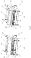
- the control cabinet 31 is part of the inventively designed in this area frame 25, as shown in the Fig. 2 will be explained in more detail below.
- FIG. 2 Frame module shown differs from the corresponding in Fig. 1 shown frame module in that on the front of the frame (which in Fig. 2 behind) an upper and a lower side member 37 and at the top center another side member 37 are provided, whereas in Fig. 1 these have been omitted in order to realize a front-side extract for a so-called bottom labeler.
- the local frame 25 has on the front side further up and down provided, less space-consuming different side members 37.
- the upper rear side member of the frame 25 (which in Fig. 2 front) is formed in the area of the printing and labeling device 13 as a control cabinet 31 in which electronic components, distributors, cable guides and the like required for controlling the weighing conveyor 11 can be accommodated.
- the control cabinet 31 replaces a longitudinal carrier formed, for example, as a round tube and thus forms a supporting part of the frame 25.
- the frame 25 is constructed in a particularly compact and space-saving manner.
- the control cabinet 31 extends over the entire distance between the two side walls 33 and is on the two side cheeks 33 attached.
- the width of the control cabinet 31 corresponds to the distance between the two end-side side walls 33.
- the height and depth of the cabinet 31 is relatively small compared to its width.
- the control cabinet 31 has an identical cross-section across its width.
- the control cabinet 31 is placed in such a way that it does not protrude outwardly beyond the side walls 33 in the lateral direction, but terminates flush therewith. This ensures that the center of gravity of the control cabinet 31 - seen in the lateral direction - within the interior formed by the side walls 33, in particular by the feet 35 of the side walls 33 of the frame 25 is arranged. This counteracts tilting of the frame 25 and thus contributes to the stability of the frame 25.
- the control cabinet 41 does not protrude upward beyond the side walls 33. Below the cabinet 41 designed as an L or flat profile lower side member 37 is provided.
- the interior of the cabinet 31 is accessible via a flap 41 which in Fig. 2a in their closed position and in Fig. 2b is shown in its open position.
- a flap 41 which in Fig. 2a in their closed position and in Fig. 2b is shown in its open position.
- cable glands cables can be passed.
- corresponding cable glands are provided on the cable glands.
- a cable rake 43 is provided below the cabinet 41, which serves as a sorting aid for the guided into the cabinet 31 or led out of the cabinet 31 cable.
- control cabinet 31 By integrating the control cabinet 31 in the supporting structure of the frame 25, a particularly compact design of the frame or the respective module thereof can be realized.
Landscapes
- Engineering & Computer Science (AREA)
- Mechanical Engineering (AREA)
- Physics & Mathematics (AREA)
- General Physics & Mathematics (AREA)
- Quality & Reliability (AREA)
- Sorting Of Articles (AREA)
- Control Of Conveyors (AREA)
- Forklifts And Lifting Vehicles (AREA)
- Weight Measurement For Supplying Or Discharging Of Specified Amounts Of Material (AREA)
- Basic Packing Technique (AREA)
Claims (10)
- Bâti (25) d'un dispositif de transport et de pesée (11), comportant deux joues latérales (33) du côté frontal et plusieurs supports longitudinaux (31, 37) reliant les deux joues latérales (33) l'une à l'autre, l'un des supports longitudinaux (31, 37) étant réalisé sous la forme d'une armoire de commande (31) pour le dispositif de transport et de pesée (11), dont la largeur s'étend sur toute la distance libre entre les deux joues latérales (33),
caractérisé en ce que
l'armoire de commande (31) est réalisée sous la forme d'un support longitudinal (31) latéral supérieur. - Bâti selon la revendication 1,
caractérisé en ce que
l'armoire de commande (31) présente sa plus longue extension dans la direction de l'extension longitudinale des supports longitudinaux (31, 37). - Bâti selon la revendication 1 ou 2,
caractérisé en ce que
l'armoire de commande (31) présente une face supérieure, une paroi arrière et une face inférieure qui sont reliées entre elles en une seule pièce et qui sont fabriquées en particulier en tôle pliée. - Bâti selon l'une au moins des revendications précédentes,
caractérisé en ce que
le centre de masse de l'armoire de commande (31) est situé en direction latérale à l'intérieur de l'espace intérieur du bâti (25) formé par les joues latérales (33), en particulier par les pieds d'appui (35) des joues latérales (33). - Bâti selon l'une au moins des revendications précédentes,
caractérisé en ce que
l'armoire de commande (31) est positionnée de telle sorte qu'elle dépasse vers l'extérieur au maximum de 20 % de son extension en profondeur au-delà de l'extrémité latérale des joues latérales (33) et qu'elle se termine en particulier en affleurement avec l'extrémité latérale des joues latérales (33). - Bâti selon l'une au moins des revendications précédentes,
caractérisé en ce que
l'armoire de commande (31) est disposée au-dessous d'une extrémité supérieure des joues latérales (33). - Bâti selon l'une au moins des revendications précédentes,
caractérisé en ce que
l'armoire de commande (31) présente un volet (41) qui peut être ouvert par rabattement vers l'extérieur. - Bâti selon l'une au moins des revendications précédentes,
caractérisé en ce que
des passe-câbles réalisés dans l'armoire de commande (31) sont munis de presse-étoupes et/ou de joints de câble, et/ou un râtelier de câble (43) est disposé au-dessous de l'armoire de commande (31). - Bâti selon l'une au moins des revendications précédentes,
caractérisé en ce que
une partie au moins des supports longitudinaux (37) restants est réalisée en acier plat et/ou sous forme de tube rond, et/ou la longueur d'une partie au moins des supports longitudinaux (37) restants correspond à la largeur de l'armoire de commande (31). - Dispositif de transport et de pesée (11) comportant une plate-forme de pesée (19), au moins une bande transporteuse (15, 17) et un bâti (25) selon l'une des revendications précédentes.
Applications Claiming Priority (2)
| Application Number | Priority Date | Filing Date | Title |
|---|---|---|---|
| DE102013203460.1A DE102013203460A1 (de) | 2013-02-28 | 2013-02-28 | Gestell einer Wäge-Fördervorrichtung |
| PCT/EP2014/051834 WO2014131568A1 (fr) | 2013-02-28 | 2014-01-30 | Bâti d'un dispositif de transport et de pesée |
Publications (3)
| Publication Number | Publication Date |
|---|---|
| EP2938975A1 EP2938975A1 (fr) | 2015-11-04 |
| EP2938975B1 true EP2938975B1 (fr) | 2019-11-27 |
| EP2938975B2 EP2938975B2 (fr) | 2022-11-23 |
Family
ID=50064566
Family Applications (1)
| Application Number | Title | Priority Date | Filing Date |
|---|---|---|---|
| EP14702795.7A Active EP2938975B2 (fr) | 2013-02-28 | 2014-01-30 | Bâti d'un dispositif de transport et de pesée |
Country Status (4)
| Country | Link |
|---|---|
| EP (1) | EP2938975B2 (fr) |
| DE (1) | DE102013203460A1 (fr) |
| ES (1) | ES2774434T5 (fr) |
| WO (1) | WO2014131568A1 (fr) |
Families Citing this family (1)
| Publication number | Priority date | Publication date | Assignee | Title |
|---|---|---|---|---|
| EP3674673B1 (fr) | 2018-12-28 | 2022-03-30 | Bizerba SE & Co. KG | Dispositif de transport et de pesage protégé contre les manipulations |
Citations (13)
| Publication number | Priority date | Publication date | Assignee | Title |
|---|---|---|---|---|
| JPH11351948A (ja) | 1998-06-04 | 1999-12-24 | Anritsu Corp | 計量装置 |
| JP2002116079A (ja) | 2000-10-06 | 2002-04-19 | Ishida Co Ltd | 品質検査機器 |
| EP1524210A1 (fr) | 2003-10-16 | 2005-04-20 | Kolbus GmbH & Co. KG | Convoyeur avec parois laterales profilées |
| DE10357982A1 (de) | 2003-12-11 | 2005-07-07 | Garvens Automation Gmbh | Gestell für eine Kontrollwaage |
| JP2005187170A (ja) | 2003-12-26 | 2005-07-14 | Anritsu Sanki System Co Ltd | 重量選別装置 |
| DE102007032270A1 (de) | 2007-07-11 | 2009-01-15 | Mettler-Toledo Garvens Gmbh | Vorrichtung zum Prüfen von Produkten und Prüfverfahren |
| DE102008063854A1 (de) | 2008-12-19 | 2010-08-26 | Stiebel Eltron Gmbh & Co. Kg | Haustechnikgerät und Rahmen für ein Haustechnikgerät |
| WO2010095438A1 (fr) | 2009-02-20 | 2010-08-26 | 株式会社鈴木製作所 | Machine d'emballage de film d'étanchéité sur trois côtés |
| WO2011030135A1 (fr) | 2009-09-08 | 2011-03-17 | Ishida Europe Limited | Chaîne de traitement |
| JP2011075508A (ja) | 2009-10-01 | 2011-04-14 | Yamato Scale Co Ltd | 重量検査装置 |
| DE102009047090A1 (de) | 2009-11-24 | 2011-05-26 | Bizerba Gmbh & Co. Kg | Wäge-Fördervorrichtung |
| JP3171810U (ja) | 2011-09-06 | 2011-11-17 | 大和製衡株式会社 | 重量選別機の高さ調節装置 |
| US20130199900A1 (en) | 2012-02-08 | 2013-08-08 | Pteris Global Limited | Belt conveyor assembly |
Family Cites Families (2)
| Publication number | Priority date | Publication date | Assignee | Title |
|---|---|---|---|---|
| US2366075A (en) * | 1940-11-28 | 1944-12-26 | Carl S Weyandt | Weighing and feeding device |
| US4578926A (en) * | 1983-03-02 | 1986-04-01 | Kabushiki Kaisha Ishida Koki Seisakusho | Apparatus for packaging, weighing and labeling merchandise |
-
2013
- 2013-02-28 DE DE102013203460.1A patent/DE102013203460A1/de not_active Withdrawn
-
2014
- 2014-01-30 EP EP14702795.7A patent/EP2938975B2/fr active Active
- 2014-01-30 WO PCT/EP2014/051834 patent/WO2014131568A1/fr not_active Ceased
- 2014-01-30 ES ES14702795T patent/ES2774434T5/es active Active
Patent Citations (13)
| Publication number | Priority date | Publication date | Assignee | Title |
|---|---|---|---|---|
| JPH11351948A (ja) | 1998-06-04 | 1999-12-24 | Anritsu Corp | 計量装置 |
| JP2002116079A (ja) | 2000-10-06 | 2002-04-19 | Ishida Co Ltd | 品質検査機器 |
| EP1524210A1 (fr) | 2003-10-16 | 2005-04-20 | Kolbus GmbH & Co. KG | Convoyeur avec parois laterales profilées |
| DE10357982A1 (de) | 2003-12-11 | 2005-07-07 | Garvens Automation Gmbh | Gestell für eine Kontrollwaage |
| JP2005187170A (ja) | 2003-12-26 | 2005-07-14 | Anritsu Sanki System Co Ltd | 重量選別装置 |
| DE102007032270A1 (de) | 2007-07-11 | 2009-01-15 | Mettler-Toledo Garvens Gmbh | Vorrichtung zum Prüfen von Produkten und Prüfverfahren |
| DE102008063854A1 (de) | 2008-12-19 | 2010-08-26 | Stiebel Eltron Gmbh & Co. Kg | Haustechnikgerät und Rahmen für ein Haustechnikgerät |
| WO2010095438A1 (fr) | 2009-02-20 | 2010-08-26 | 株式会社鈴木製作所 | Machine d'emballage de film d'étanchéité sur trois côtés |
| WO2011030135A1 (fr) | 2009-09-08 | 2011-03-17 | Ishida Europe Limited | Chaîne de traitement |
| JP2011075508A (ja) | 2009-10-01 | 2011-04-14 | Yamato Scale Co Ltd | 重量検査装置 |
| DE102009047090A1 (de) | 2009-11-24 | 2011-05-26 | Bizerba Gmbh & Co. Kg | Wäge-Fördervorrichtung |
| JP3171810U (ja) | 2011-09-06 | 2011-11-17 | 大和製衡株式会社 | 重量選別機の高さ調節装置 |
| US20130199900A1 (en) | 2012-02-08 | 2013-08-08 | Pteris Global Limited | Belt conveyor assembly |
Also Published As
| Publication number | Publication date |
|---|---|
| EP2938975B2 (fr) | 2022-11-23 |
| ES2774434T8 (es) | 2020-09-18 |
| EP2938975A1 (fr) | 2015-11-04 |
| ES2774434T3 (es) | 2020-07-21 |
| ES2774434T5 (es) | 2023-04-18 |
| DE102013203460A1 (de) | 2014-08-28 |
| WO2014131568A1 (fr) | 2014-09-04 |
Similar Documents
| Publication | Publication Date | Title |
|---|---|---|
| EP2609021B1 (fr) | Système de rayonnage pour le stockage de produits à stocker | |
| EP1934120B1 (fr) | Rayonnage dote d'une pluralite d'unites de rayonnage | |
| EP3281891A1 (fr) | Système de transfert comprenant un dispositif de poussée pour marchandises au détail | |
| EP2124302A1 (fr) | Baie pour une cellule d'essai | |
| DE102013203457B4 (de) | Gestell einer Wäge-Fördervorrichtung | |
| EP1693145B1 (fr) | Installation d'usinage avec pince porte-pièce mobile verticalement | |
| EP2938544B1 (fr) | Machine d'étiquettage | |
| DE69218608T2 (de) | Speicherabdeckung | |
| EP2865614B1 (fr) | Bâti pour une installation de tapis de transport | |
| EP2746193B1 (fr) | Véhicule pour entrepôt, transstockeur, entrepôt et procédé correspondant | |
| EP3347662B1 (fr) | Refroidisseur pour le refroidissement de produit en vrac chaud | |
| EP2504674B1 (fr) | Ensemble de pesage et de convoyage | |
| EP3053838B1 (fr) | Dispositif modulaire d'emballage de cigarettes ou de paquets de cigarettes | |
| EP1452265B1 (fr) | Plateforme de base pour un système de manipulation et système de manipulation | |
| EP2938975B1 (fr) | Bâti d'un dispositif de transport et de pesée | |
| EP2923955B1 (fr) | Dispositif de traitement de produits alimentaires | |
| EP1932778B1 (fr) | Dispositif de stockage | |
| CH659921A5 (de) | Mobile elektrische einrichtung. | |
| EP2746172B1 (fr) | Procédé et dispositif de pesage de gerbes sur un dispositif de transport | |
| EP0822739A2 (fr) | Appareil automatisé de test de cartes de circuit électronique | |
| DE102022113795A1 (de) | Shuttle für ein Regalsystem | |
| DE102004044846B4 (de) | Anlage zum Abfüllen | |
| DE29806027U1 (de) | Lager- und Transportsystem | |
| EP3772466B1 (fr) | Système de marquage de prix | |
| EP3276099B1 (fr) | Conteneur de transport |
Legal Events
| Date | Code | Title | Description |
|---|---|---|---|
| PUAI | Public reference made under article 153(3) epc to a published international application that has entered the european phase |
Free format text: ORIGINAL CODE: 0009012 |
|
| 17P | Request for examination filed |
Effective date: 20150730 |
|
| AK | Designated contracting states |
Kind code of ref document: A1 Designated state(s): AL AT BE BG CH CY CZ DE DK EE ES FI FR GB GR HR HU IE IS IT LI LT LU LV MC MK MT NL NO PL PT RO RS SE SI SK SM TR |
|
| AX | Request for extension of the european patent |
Extension state: BA ME |
|
| DAX | Request for extension of the european patent (deleted) | ||
| RAP1 | Party data changed (applicant data changed or rights of an application transferred) |
Owner name: BIZERBA SE & CO. KG |
|
| RIC1 | Information provided on ipc code assigned before grant |
Ipc: B65B 65/00 20060101ALI20190515BHEP Ipc: G01G 21/28 20060101ALI20190515BHEP Ipc: G01G 11/00 20060101AFI20190515BHEP Ipc: B65B 1/46 20060101ALI20190515BHEP Ipc: G01G 21/23 20060101ALI20190515BHEP Ipc: B65B 59/04 20060101ALI20190515BHEP |
|
| GRAP | Despatch of communication of intention to grant a patent |
Free format text: ORIGINAL CODE: EPIDOSNIGR1 |
|
| STAA | Information on the status of an ep patent application or granted ep patent |
Free format text: STATUS: GRANT OF PATENT IS INTENDED |
|
| INTG | Intention to grant announced |
Effective date: 20190621 |
|
| GRAS | Grant fee paid |
Free format text: ORIGINAL CODE: EPIDOSNIGR3 |
|
| GRAA | (expected) grant |
Free format text: ORIGINAL CODE: 0009210 |
|
| STAA | Information on the status of an ep patent application or granted ep patent |
Free format text: STATUS: THE PATENT HAS BEEN GRANTED |
|
| AK | Designated contracting states |
Kind code of ref document: B1 Designated state(s): AL AT BE BG CH CY CZ DE DK EE ES FI FR GB GR HR HU IE IS IT LI LT LU LV MC MK MT NL NO PL PT RO RS SE SI SK SM TR |
|
| REG | Reference to a national code |
Ref country code: GB Ref legal event code: FG4D Free format text: NOT ENGLISH |
|
| REG | Reference to a national code |
Ref country code: CH Ref legal event code: EP |
|
| REG | Reference to a national code |
Ref country code: DE Ref legal event code: R096 Ref document number: 502014013120 Country of ref document: DE |
|
| REG | Reference to a national code |
Ref country code: AT Ref legal event code: REF Ref document number: 1207211 Country of ref document: AT Kind code of ref document: T Effective date: 20191215 |
|
| REG | Reference to a national code |
Ref country code: IE Ref legal event code: FG4D Free format text: LANGUAGE OF EP DOCUMENT: GERMAN |
|
| REG | Reference to a national code |
Ref country code: CH Ref legal event code: NV Representative=s name: DR. GRAF AND PARTNER AG INTELLECTUAL PROPERTY, CH |
|
| REG | Reference to a national code |
Ref country code: NL Ref legal event code: MP Effective date: 20191127 |
|
| REG | Reference to a national code |
Ref country code: LT Ref legal event code: MG4D |
|
| PG25 | Lapsed in a contracting state [announced via postgrant information from national office to epo] |
Ref country code: NL Free format text: LAPSE BECAUSE OF FAILURE TO SUBMIT A TRANSLATION OF THE DESCRIPTION OR TO PAY THE FEE WITHIN THE PRESCRIBED TIME-LIMIT Effective date: 20191127 Ref country code: LT Free format text: LAPSE BECAUSE OF FAILURE TO SUBMIT A TRANSLATION OF THE DESCRIPTION OR TO PAY THE FEE WITHIN THE PRESCRIBED TIME-LIMIT Effective date: 20191127 Ref country code: BG Free format text: LAPSE BECAUSE OF FAILURE TO SUBMIT A TRANSLATION OF THE DESCRIPTION OR TO PAY THE FEE WITHIN THE PRESCRIBED TIME-LIMIT Effective date: 20200227 Ref country code: NO Free format text: LAPSE BECAUSE OF FAILURE TO SUBMIT A TRANSLATION OF THE DESCRIPTION OR TO PAY THE FEE WITHIN THE PRESCRIBED TIME-LIMIT Effective date: 20200227 Ref country code: FI Free format text: LAPSE BECAUSE OF FAILURE TO SUBMIT A TRANSLATION OF THE DESCRIPTION OR TO PAY THE FEE WITHIN THE PRESCRIBED TIME-LIMIT Effective date: 20191127 Ref country code: GR Free format text: LAPSE BECAUSE OF FAILURE TO SUBMIT A TRANSLATION OF THE DESCRIPTION OR TO PAY THE FEE WITHIN THE PRESCRIBED TIME-LIMIT Effective date: 20200228 Ref country code: LV Free format text: LAPSE BECAUSE OF FAILURE TO SUBMIT A TRANSLATION OF THE DESCRIPTION OR TO PAY THE FEE WITHIN THE PRESCRIBED TIME-LIMIT Effective date: 20191127 Ref country code: SE Free format text: LAPSE BECAUSE OF FAILURE TO SUBMIT A TRANSLATION OF THE DESCRIPTION OR TO PAY THE FEE WITHIN THE PRESCRIBED TIME-LIMIT Effective date: 20191127 |
|
| PG25 | Lapsed in a contracting state [announced via postgrant information from national office to epo] |
Ref country code: HR Free format text: LAPSE BECAUSE OF FAILURE TO SUBMIT A TRANSLATION OF THE DESCRIPTION OR TO PAY THE FEE WITHIN THE PRESCRIBED TIME-LIMIT Effective date: 20191127 Ref country code: RS Free format text: LAPSE BECAUSE OF FAILURE TO SUBMIT A TRANSLATION OF THE DESCRIPTION OR TO PAY THE FEE WITHIN THE PRESCRIBED TIME-LIMIT Effective date: 20191127 Ref country code: IS Free format text: LAPSE BECAUSE OF FAILURE TO SUBMIT A TRANSLATION OF THE DESCRIPTION OR TO PAY THE FEE WITHIN THE PRESCRIBED TIME-LIMIT Effective date: 20200327 |
|
| PG25 | Lapsed in a contracting state [announced via postgrant information from national office to epo] |
Ref country code: AL Free format text: LAPSE BECAUSE OF FAILURE TO SUBMIT A TRANSLATION OF THE DESCRIPTION OR TO PAY THE FEE WITHIN THE PRESCRIBED TIME-LIMIT Effective date: 20191127 |
|
| REG | Reference to a national code |
Ref country code: ES Ref legal event code: FG2A Ref document number: 2774434 Country of ref document: ES Kind code of ref document: T3 Effective date: 20200721 |
|
| PG25 | Lapsed in a contracting state [announced via postgrant information from national office to epo] |
Ref country code: RO Free format text: LAPSE BECAUSE OF FAILURE TO SUBMIT A TRANSLATION OF THE DESCRIPTION OR TO PAY THE FEE WITHIN THE PRESCRIBED TIME-LIMIT Effective date: 20191127 Ref country code: DK Free format text: LAPSE BECAUSE OF FAILURE TO SUBMIT A TRANSLATION OF THE DESCRIPTION OR TO PAY THE FEE WITHIN THE PRESCRIBED TIME-LIMIT Effective date: 20191127 Ref country code: EE Free format text: LAPSE BECAUSE OF FAILURE TO SUBMIT A TRANSLATION OF THE DESCRIPTION OR TO PAY THE FEE WITHIN THE PRESCRIBED TIME-LIMIT Effective date: 20191127 Ref country code: CZ Free format text: LAPSE BECAUSE OF FAILURE TO SUBMIT A TRANSLATION OF THE DESCRIPTION OR TO PAY THE FEE WITHIN THE PRESCRIBED TIME-LIMIT Effective date: 20191127 Ref country code: PT Free format text: LAPSE BECAUSE OF FAILURE TO SUBMIT A TRANSLATION OF THE DESCRIPTION OR TO PAY THE FEE WITHIN THE PRESCRIBED TIME-LIMIT Effective date: 20200419 |
|
| REG | Reference to a national code |
Ref country code: DE Ref legal event code: R026 Ref document number: 502014013120 Country of ref document: DE |
|
| PG25 | Lapsed in a contracting state [announced via postgrant information from national office to epo] |
Ref country code: SM Free format text: LAPSE BECAUSE OF FAILURE TO SUBMIT A TRANSLATION OF THE DESCRIPTION OR TO PAY THE FEE WITHIN THE PRESCRIBED TIME-LIMIT Effective date: 20191127 Ref country code: SK Free format text: LAPSE BECAUSE OF FAILURE TO SUBMIT A TRANSLATION OF THE DESCRIPTION OR TO PAY THE FEE WITHIN THE PRESCRIBED TIME-LIMIT Effective date: 20191127 Ref country code: MC Free format text: LAPSE BECAUSE OF FAILURE TO SUBMIT A TRANSLATION OF THE DESCRIPTION OR TO PAY THE FEE WITHIN THE PRESCRIBED TIME-LIMIT Effective date: 20191127 |
|
| PLBI | Opposition filed |
Free format text: ORIGINAL CODE: 0009260 |
|
| PLAB | Opposition data, opponent's data or that of the opponent's representative modified |
Free format text: ORIGINAL CODE: 0009299OPPO |
|
| PLAX | Notice of opposition and request to file observation + time limit sent |
Free format text: ORIGINAL CODE: EPIDOSNOBS2 |
|
| 26 | Opposition filed |
Opponent name: MULTIVAC SEPP HAGGENMUELLER SE & CO. KG Effective date: 20200826 |
|
| R26 | Opposition filed (corrected) |
Opponent name: MULTIVAC MARKING & INSPECTION GMBH & CO. KG Effective date: 20200826 |
|
| REG | Reference to a national code |
Ref country code: BE Ref legal event code: MM Effective date: 20200131 |
|
| PG25 | Lapsed in a contracting state [announced via postgrant information from national office to epo] |
Ref country code: LU Free format text: LAPSE BECAUSE OF NON-PAYMENT OF DUE FEES Effective date: 20200130 |
|
| PG25 | Lapsed in a contracting state [announced via postgrant information from national office to epo] |
Ref country code: SI Free format text: LAPSE BECAUSE OF FAILURE TO SUBMIT A TRANSLATION OF THE DESCRIPTION OR TO PAY THE FEE WITHIN THE PRESCRIBED TIME-LIMIT Effective date: 20191127 Ref country code: PL Free format text: LAPSE BECAUSE OF FAILURE TO SUBMIT A TRANSLATION OF THE DESCRIPTION OR TO PAY THE FEE WITHIN THE PRESCRIBED TIME-LIMIT Effective date: 20191127 Ref country code: BE Free format text: LAPSE BECAUSE OF NON-PAYMENT OF DUE FEES Effective date: 20200131 |
|
| PG25 | Lapsed in a contracting state [announced via postgrant information from national office to epo] |
Ref country code: IE Free format text: LAPSE BECAUSE OF NON-PAYMENT OF DUE FEES Effective date: 20200130 |
|
| PLBB | Reply of patent proprietor to notice(s) of opposition received |
Free format text: ORIGINAL CODE: EPIDOSNOBS3 |
|
| REG | Reference to a national code |
Ref country code: AT Ref legal event code: MM01 Ref document number: 1207211 Country of ref document: AT Kind code of ref document: T Effective date: 20200130 |
|
| PG25 | Lapsed in a contracting state [announced via postgrant information from national office to epo] |
Ref country code: AT Free format text: LAPSE BECAUSE OF NON-PAYMENT OF DUE FEES Effective date: 20200130 |
|
| PG25 | Lapsed in a contracting state [announced via postgrant information from national office to epo] |
Ref country code: TR Free format text: LAPSE BECAUSE OF FAILURE TO SUBMIT A TRANSLATION OF THE DESCRIPTION OR TO PAY THE FEE WITHIN THE PRESCRIBED TIME-LIMIT Effective date: 20191127 Ref country code: MT Free format text: LAPSE BECAUSE OF FAILURE TO SUBMIT A TRANSLATION OF THE DESCRIPTION OR TO PAY THE FEE WITHIN THE PRESCRIBED TIME-LIMIT Effective date: 20191127 Ref country code: CY Free format text: LAPSE BECAUSE OF FAILURE TO SUBMIT A TRANSLATION OF THE DESCRIPTION OR TO PAY THE FEE WITHIN THE PRESCRIBED TIME-LIMIT Effective date: 20191127 |
|
| PG25 | Lapsed in a contracting state [announced via postgrant information from national office to epo] |
Ref country code: MK Free format text: LAPSE BECAUSE OF FAILURE TO SUBMIT A TRANSLATION OF THE DESCRIPTION OR TO PAY THE FEE WITHIN THE PRESCRIBED TIME-LIMIT Effective date: 20191127 |
|
| PUAH | Patent maintained in amended form |
Free format text: ORIGINAL CODE: 0009272 |
|
| STAA | Information on the status of an ep patent application or granted ep patent |
Free format text: STATUS: PATENT MAINTAINED AS AMENDED |
|
| 27A | Patent maintained in amended form |
Effective date: 20221123 |
|
| AK | Designated contracting states |
Kind code of ref document: B2 Designated state(s): AL AT BE BG CH CY CZ DE DK EE ES FI FR GB GR HR HU IE IS IT LI LT LU LV MC MK MT NL NO PL PT RO RS SE SI SK SM TR |
|
| REG | Reference to a national code |
Ref country code: DE Ref legal event code: R102 Ref document number: 502014013120 Country of ref document: DE |
|
| REG | Reference to a national code |
Ref country code: ES Ref legal event code: DC2A Ref document number: 2774434 Country of ref document: ES Kind code of ref document: T5 Effective date: 20230418 |
|
| REG | Reference to a national code |
Ref country code: CH Ref legal event code: U11 Free format text: ST27 STATUS EVENT CODE: U-0-0-U10-U11 (AS PROVIDED BY THE NATIONAL OFFICE) Effective date: 20260201 |
|
| PGFP | Annual fee paid to national office [announced via postgrant information from national office to epo] |
Ref country code: GB Payment date: 20260122 Year of fee payment: 13 |
|
| PGFP | Annual fee paid to national office [announced via postgrant information from national office to epo] |
Ref country code: ES Payment date: 20260217 Year of fee payment: 13 |
|
| PGFP | Annual fee paid to national office [announced via postgrant information from national office to epo] |
Ref country code: DE Payment date: 20260120 Year of fee payment: 13 |
|
| PGFP | Annual fee paid to national office [announced via postgrant information from national office to epo] |
Ref country code: IT Payment date: 20260130 Year of fee payment: 13 |
|
| PGFP | Annual fee paid to national office [announced via postgrant information from national office to epo] |
Ref country code: FR Payment date: 20260127 Year of fee payment: 13 |
|
| PGFP | Annual fee paid to national office [announced via postgrant information from national office to epo] |
Ref country code: CH Payment date: 20260201 Year of fee payment: 13 |