EP2939577A1 - Ladevorrichtung für zubereitungseinheiten von verkaufsautomaten - Google Patents
Ladevorrichtung für zubereitungseinheiten von verkaufsautomaten Download PDFInfo
- Publication number
- EP2939577A1 EP2939577A1 EP15165267.4A EP15165267A EP2939577A1 EP 2939577 A1 EP2939577 A1 EP 2939577A1 EP 15165267 A EP15165267 A EP 15165267A EP 2939577 A1 EP2939577 A1 EP 2939577A1
- Authority
- EP
- European Patent Office
- Prior art keywords
- container
- slide
- actuator member
- rotary table
- slides
- Prior art date
- Legal status (The legal status is an assumption and is not a legal conclusion. Google has not performed a legal analysis and makes no representation as to the accuracy of the status listed.)
- Withdrawn
Links
- 238000002360 preparation method Methods 0.000 title claims abstract description 28
- 239000004615 ingredient Substances 0.000 claims abstract description 14
- 239000000843 powder Substances 0.000 abstract description 16
- 235000015243 ice cream Nutrition 0.000 description 7
- 238000007710 freezing Methods 0.000 description 6
- 230000008014 freezing Effects 0.000 description 6
- 235000013361 beverage Nutrition 0.000 description 3
- 235000013305 food Nutrition 0.000 description 3
- 235000003363 Cornus mas Nutrition 0.000 description 2
- 240000006766 Cornus mas Species 0.000 description 2
- 238000004140 cleaning Methods 0.000 description 2
- 238000004891 communication Methods 0.000 description 2
- 239000006185 dispersion Substances 0.000 description 2
- 239000007788 liquid Substances 0.000 description 2
- 238000012423 maintenance Methods 0.000 description 2
- RSIWALKZYXPAGW-NSHDSACASA-N 6-(3-fluorophenyl)-3-methyl-7-[(1s)-1-(7h-purin-6-ylamino)ethyl]-[1,3]thiazolo[3,2-a]pyrimidin-5-one Chemical compound C=1([C@@H](NC=2C=3N=CNC=3N=CN=2)C)N=C2SC=C(C)N2C(=O)C=1C1=CC=CC(F)=C1 RSIWALKZYXPAGW-NSHDSACASA-N 0.000 description 1
- 235000019219 chocolate Nutrition 0.000 description 1
- 238000001816 cooling Methods 0.000 description 1
- 230000008878 coupling Effects 0.000 description 1
- 238000010168 coupling process Methods 0.000 description 1
- 238000005859 coupling reaction Methods 0.000 description 1
- 239000006071 cream Substances 0.000 description 1
- 238000006073 displacement reaction Methods 0.000 description 1
- 239000000796 flavoring agent Substances 0.000 description 1
- 235000019634 flavors Nutrition 0.000 description 1
- 239000012530 fluid Substances 0.000 description 1
- 235000015110 jellies Nutrition 0.000 description 1
- 239000000463 material Substances 0.000 description 1
- 239000000203 mixture Substances 0.000 description 1
- 238000012544 monitoring process Methods 0.000 description 1
- 230000000737 periodic effect Effects 0.000 description 1
- 238000011012 sanitization Methods 0.000 description 1
- 235000015067 sauces Nutrition 0.000 description 1
Images


Classifications
-
- A—HUMAN NECESSITIES
- A47—FURNITURE; DOMESTIC ARTICLES OR APPLIANCES; COFFEE MILLS; SPICE MILLS; SUCTION CLEANERS IN GENERAL
- A47J—KITCHEN EQUIPMENT; COFFEE MILLS; SPICE MILLS; APPARATUS FOR MAKING BEVERAGES
- A47J31/00—Apparatus for making beverages
- A47J31/40—Beverage-making apparatus with dispensing means for adding a measured quantity of ingredients, e.g. coffee, water, sugar, cocoa, milk, tea
- A47J31/404—Powder dosing devices
-
- A—HUMAN NECESSITIES
- A23—FOODS OR FOODSTUFFS; TREATMENT THEREOF, NOT COVERED BY OTHER CLASSES
- A23G—COCOA; COCOA PRODUCTS, e.g. CHOCOLATE; SUBSTITUTES FOR COCOA OR COCOA PRODUCTS; CONFECTIONERY; CHEWING GUM; ICE-CREAM; PREPARATION THEREOF
- A23G9/00—Frozen sweets, e.g. ice confectionery, ice-cream; Mixtures therefor
- A23G9/04—Production of frozen sweets, e.g. ice-cream
- A23G9/22—Details, component parts or accessories of apparatus insofar as not peculiar to a single one of the preceding groups
-
- A—HUMAN NECESSITIES
- A47—FURNITURE; DOMESTIC ARTICLES OR APPLIANCES; COFFEE MILLS; SPICE MILLS; SUCTION CLEANERS IN GENERAL
- A47J—KITCHEN EQUIPMENT; COFFEE MILLS; SPICE MILLS; APPARATUS FOR MAKING BEVERAGES
- A47J31/00—Apparatus for making beverages
- A47J31/40—Beverage-making apparatus with dispensing means for adding a measured quantity of ingredients, e.g. coffee, water, sugar, cocoa, milk, tea
Definitions
- the present invention relates to an ingredient-loading device for preparation units of vending machines.
- the present invention is advantageously employed for loading powders into preparation units for preparing beverages, sorbets, ice-creams and the like in vending machines.
- vending machines In the preparation of ice-cream products, such as ice-creams, slushes, sorbets, creams, sauces, semi-liquid chocolate, jellies and the like, but also in the preparation of beverages in vending machines, hygiene is of critical importance. Indeed, vending machines are not designed to undergo maintenance each time dispensing occurs, but only after many dispensing operations.
- vending machines are designed to undergo periodic cleaning and sanitization cycles of all the devices involved in product preparation. Nevertheless, these cleaning cycles considerably complicate both the structure and the operation logic of vending machines, thereby increasing their operating costs and, in certain cases, affecting reliability.
- the Applicant believes that advantages would be obtained from equipping vending machines, and particularly vending machines for preparation of ice-cream products, with an ingredient-loading device that would dispense ingredients into the preparation device, e.g. a batch freezer, in as aseptic a manner as possible, i.e. without leaving product residues in the vending machine or near the batch freezer.
- an ingredient-loading device that would dispense ingredients into the preparation device, e.g. a batch freezer, in as aseptic a manner as possible, i.e. without leaving product residues in the vending machine or near the batch freezer.
- the object of the present invention is to provide an ingredient-loading device for preparation units of vending machines, that can introduce ingredients into a preparation device in controlled and hygienic fashion.
- the device 1 as shown in the annexed figures has been represented schematically, and its parts are not necessarily illustrated to scale.
- An ingredient-loading device for preparation units of vending machines according to the present invention will be generally designated by numeral 1.
- Such type of batch freezer comprises a batch freezing cylinder, referenced 100 in the figures, which has a hole 101 for receiving powders. A liquid is also introduced into the batch freezing cylinder, which is designed to mix with the powder ingredients.
- the batch freezing cylinder 100 may be partially surrounded by cooling members (not shown), which are designed to reduce the temperature of the cylinder walls to values ranging from -5 to -30°C, for example -15°C.
- a pair of pistons are operative in the batch freezing cylinder 100, and synchronously reciprocate therein. i.e. move up and down in the cylinder in synchronization with each other, to prepare the ice-cream product. Once such product has been prepared, it is ejected from an ejection opening of the batch freezing cylinder to be dispensed to the user.
- the device 1 comprises a plurality of containers 2 for preferably powdered ingredients, each equipped with a dispensing element 3 designed to at least partially fit into an opening 101 of a preparation unit 100.
- the dispensing element 3 is a hollow cylinder, which is put in fluid communication with the interior of the container 2 and extends away from such container.
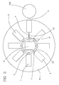
- the dispensing element 3 extends beyond the plan layout of the container (as schematically shown in Figure 3 ), for reasons that will be clarified below.
- Each container 2 is designed to contain food powders and has a substantially hopper-like structure.
- Each container 2 has a loading opening for receiving ingredients and an outlet in communication with the dispensing element 3.
- the device 1 further comprises a plurality of slides 4, each being coupled to a respective container 2.
- each slide 4 has wheels 5 for easy displacement thereof on a surface.
- the containers 2 are removably attached to the slides 4, which allows them to be removed by an operator for maintenance of the device 1. When the containers 2 are fitted onto their respective slides 4, the containers 2 and the slides 4 form a single rigid body.
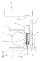
- the slides 4 are adapted to move between a rest position (as shown in Figure 2 ), in which the dispensing element lies distal from the preparation unit 100 and an operating position (as shown in Figure 1 ) in which the dispensing element 3 lies in a position in which it is at least partially inserted in the preparation unit 100, and particularly at least partially extends into the inlet 101 of the batch freezing cylinder.
- the device 1 a first actuator member 6, which is selectively operative on a single container 2 and/or its respective slide 4.
- the first actuator member 6 is operative on the container 2, which is rigidly joined to the slide 4 and transfers motion thereto. It shall be noted that the first actuator member 2 is operative on one container at a time, whereby a single actuator member 6 may be used for selectively moving all the containers 2 and their respective slides 4.
- Second actuator members 7 are also provided, which are operative on each container 2 and/or its respective slide 4, and are designed to mate with the first actuator member 6 to move the slide 4. In the preferred embodiment of the invention, the second actuator members 7 are directly operative on each container 2.
- the slides 4 and their containers 2 are supported by a rotary plate 8, which is adapted to rotate about an axis of rotation X.
- the rotary table 7 has a substantially circular shape and has a central hole with a post 9 extending therethrough, along the above mentioned axis X.
- the rotary table 8 is driven by an electric motor (not shown) via any appropriate mechanism (such as a rack and pinion arrangement).
- the electric motor is preferably equipped with an encoder to detect the position assumed by the rotary table at each instant.
- the slides 4 are slidably attached to one another in directions perpendicular to the axis of rotation X of the rotary table 4.
- elastic members 10 are provided (as schematically shown in Figures 1 and 2 ), which are operable between each slide 4 and the rotary table 8 and are designed to hold the slides 4 in the rest position, proximate to the post 9.
- each slide 4 ha a stem 4a which extends below and away from the slide, and through a straight slit formed in the rotary table 8. This slit radially extends on the rotary table, parallel to the direction of movement of the slide.
- An additional stem 8a is provided below the rotary table.
- the elastic member e.g. a spring
- the elastic member is operative between the two stems. with which said slides, said rotary table being adapted to rotate to bring a container and its respective slide in front of said first actuator member.
- the first actuator member 6 comprises a tooth 11 which rotates about an axis substantially perpendicular to the axis of rotation X of the rotary table 8. This rotating tooth 11 is carried by the post 9 and extends therefrom in a radially outward direction.
- the pin 11 is actuated by an electric motor (not shown) preferably having an encoder. The purpose of the tooth 11 is to rotate the second actuator members 7.
- each container 2 and comprise a cursor 12 which has a groove for coupling with the teeth 11, such that the rotation of the tooth 11 causes the rotation of the cursor 12.
- the cursor is rigidly joined to a threaded rod 13 extending in a direction perpendicular to the axis X and parallel to the direction of movement of the slides.
- the threaded rod 13 has, for instance, helical threads on its outer surface.
- the threaded rod is inserted in a threaded bushing 14 engaged on the container 2 (see Figure 4 ).
- the rotation of the threaded rod 13 will exert a force on the container, through its connection with the threaded bushing 14, thereby causing the slide 4 to move.
- the threaded bushing is inserted in a sleeve 15 which is joined to the container 2 (see Figure 4 ).
- a rotational clutch 16 is provided between the threaded bushing 14 and the sleeve 15, which rigidly joins the bushing 16 and the sleeve 15 when the torque transmitted between the threaded bushing and the sleeve 15 is below a threshold value, and allows the threaded bushing 14 to rotate in the sleeve 15 when the above torque exceeds the threshold value.
- the threaded bushing is connected to an auger 17 which extends in the container 2 and reaches said dispensing element 3.
- the auger 17 rotates with the threaded bushing 14, thereby pushing the powder ingredient in the container 2 toward the dispensing element 3, out of the container.
- a gear wheel 18 is provided in the container 2 to increase the effectiveness of the auger 17, which gear wheel meshes with the auger and more effectively conveys the powder material toward the bottom of the container 2 and hence toward the auger 17.
- the rotary table 8 In operation, when a particular food powder is to be fed into the batch freezer, the rotary table 8 is rotated until the container 2 that contains such particular powder comes to alignment with the first actuator member 6, for the tooth 11 to fit into the groove of the cursor 12.
- the post 9 has a guide ring 19 (see particularly Figure 3 ), which is designed to slidably engage the grooves of the cursors 12 when the slide is in the rest position.
- This guide ring 19 ensures that the grooves of the cursors maintain their orientation as the rotary table rotates, by preventing the rotation of the sliders 12. It shall be noted that in this step all the slides 4 are in the rest position, and held in this position by the elastic members 10.
- the cursor 11 is actuated, to cause the rotation of the threaded rod 13.
- the latter is unscrewed from the threaded bushing 14 with which it is engaged and causes the slide 4 to move forward toward the operating position. It shall be noted that in this step the threaded bushing 14 is rigidly joined to the container 2 and does not move (rotate) relative to it.
- any further rotation of the tooth 11 and the threaded rod 13 causes the clutch 16 to slip and, as a result, the threaded bushing 14 to rotate relative to the sleeve 15 (and hence relative to the container 2).
- the rotation of the threaded bushing 14 causes the rotation of the auger 17 which pushes the powders into the dispensing element 3.
- the rotation of the auger 17 causes in turn the rotation of the gear wheel 18, which assists the powders in reaching the bottom portion of the container 2.
- the dispensing element 3 has already penetrated the opening 101 of the batch freezer 100, for the powders to be directly dispensed into the batch freezer 2.
- the rotation of the tooth 11 continues until the right amount of powders is dispensed.
- the tooth 11 is rotated in the opposite direction.
- the clutch 16 stops the rotation of the threaded bushing 14 relative to the sleeve 15 and the slide 4 moves toward the rest position. Once this position has been reached, the cycle stops until a next powder dispensing request.
- the device 1 of the present invention allows the entire container to be moved to a position in which the ingredients can be directly dispensed into the preparation unit, thereby avoiding any dispersion of ingredients in the vending machine, and ensuring hygiene thereof.
Landscapes
- Engineering & Computer Science (AREA)
- Food Science & Technology (AREA)
- Life Sciences & Earth Sciences (AREA)
- Chemical & Material Sciences (AREA)
- Polymers & Plastics (AREA)
- Vending Machines For Individual Products (AREA)
- Confectionery (AREA)
Applications Claiming Priority (1)
| Application Number | Priority Date | Filing Date | Title |
|---|---|---|---|
| ITMI20140791 | 2014-04-29 |
Publications (2)
| Publication Number | Publication Date |
|---|---|
| EP2939577A1 true EP2939577A1 (de) | 2015-11-04 |
| EP2939577A8 EP2939577A8 (de) | 2015-12-30 |
Family
ID=50981767
Family Applications (1)
| Application Number | Title | Priority Date | Filing Date |
|---|---|---|---|
| EP15165267.4A Withdrawn EP2939577A1 (de) | 2014-04-29 | 2015-04-27 | Ladevorrichtung für zubereitungseinheiten von verkaufsautomaten |
Country Status (1)
| Country | Link |
|---|---|
| EP (1) | EP2939577A1 (de) |
Cited By (1)
| Publication number | Priority date | Publication date | Assignee | Title |
|---|---|---|---|---|
| WO2019050892A1 (en) * | 2017-09-06 | 2019-03-14 | Comana Fabio | DISTRIBUTION STATION OF SUPPLEMENTS IN POWDER |
Citations (4)
| Publication number | Priority date | Publication date | Assignee | Title |
|---|---|---|---|---|
| US5816455A (en) * | 1994-05-27 | 1998-10-06 | Specialty Equipment Companies, Inc. | Method and apparatus for frozen dessert dispensing |
| US20030085237A1 (en) * | 2001-11-02 | 2003-05-08 | Paul Kateman | Method and apparatus for producing and dispensing an aerated and/or blended food product |
| US20130032611A1 (en) * | 2011-08-03 | 2013-02-07 | Christopher Dooley | Powder Dispensing Apparatus |
| EP2676581A1 (de) * | 2012-06-20 | 2013-12-25 | F.A.S. International S.p.A. | Vorrichtung zur Herstellung von Getränken für Verkaufsautomaten |
-
2015
- 2015-04-27 EP EP15165267.4A patent/EP2939577A1/de not_active Withdrawn
Patent Citations (4)
| Publication number | Priority date | Publication date | Assignee | Title |
|---|---|---|---|---|
| US5816455A (en) * | 1994-05-27 | 1998-10-06 | Specialty Equipment Companies, Inc. | Method and apparatus for frozen dessert dispensing |
| US20030085237A1 (en) * | 2001-11-02 | 2003-05-08 | Paul Kateman | Method and apparatus for producing and dispensing an aerated and/or blended food product |
| US20130032611A1 (en) * | 2011-08-03 | 2013-02-07 | Christopher Dooley | Powder Dispensing Apparatus |
| EP2676581A1 (de) * | 2012-06-20 | 2013-12-25 | F.A.S. International S.p.A. | Vorrichtung zur Herstellung von Getränken für Verkaufsautomaten |
Cited By (1)
| Publication number | Priority date | Publication date | Assignee | Title |
|---|---|---|---|---|
| WO2019050892A1 (en) * | 2017-09-06 | 2019-03-14 | Comana Fabio | DISTRIBUTION STATION OF SUPPLEMENTS IN POWDER |
Also Published As
| Publication number | Publication date |
|---|---|
| EP2939577A8 (de) | 2015-12-30 |
Similar Documents
| Publication | Publication Date | Title |
|---|---|---|
| ES2986760T3 (es) | Unidad de puerto para un aparato de procesamiento de alimentos | |
| CN106231916B (zh) | 螺旋状移动装置 | |
| EP2345332B1 (de) | Vorrichtung und Verfahren zur Herstellung gefrorener Süßwaren | |
| EP3082522B1 (de) | Getränkespender mit pulverbehälter | |
| EP4223135B1 (de) | Produktausgabemaschine | |
| US20060255066A1 (en) | Food beverage dispensing system | |
| EP2186421B1 (de) | Vorrichtung zur Herstellung einer Softeiscreme oder ähnlicher Produkte mit Portionierungsvorrichtung und Portionszählvorrichtung | |
| EP3735834C0 (de) | Rührwerk für eine maschine zum chargengefrieren und ausgaben von eiscremeprodukten, maschine mit dem rührwerk und verfahren zur herstellung von eiscremeprodukten | |
| EP3302091B1 (de) | Vorrichtung zur verarbeitung von gekühlten produkten | |
| CN101897379A (zh) | 制造和分配例如冰淇淋、冰淇淋奶昔等食品的机器 | |
| DE602009000746D1 (de) | Gerät zum Zubereiten und Verteilen von Infusionsprodukte, insbesondere Kaffee, in veränderbaren volumetrischen Mengen | |
| WO2013070834A1 (en) | Dual valve injector assembly for dispensing a food product | |
| EP2713765B1 (de) | Vorrichtung zur herstellung von gekühlten produkten | |
| WO2017108451A1 (en) | Beverage dispenser with powder container | |
| EP2939577A1 (de) | Ladevorrichtung für zubereitungseinheiten von verkaufsautomaten | |
| EP3573470B1 (de) | Vermischungsverfahren für shake-produkt | |
| JP2020500608A (ja) | 投与装置、飲料分配装置およびウオーム本体 | |
| WO2016091830A1 (en) | Beverage dispenser with powder container | |
| WO2012007772A3 (en) | Dispensing apparatus and container for dispensing frozen confections | |
| US1676377A (en) | Unit-measuring machine | |
| EP3031367A1 (de) | Getränkespender mit Pulverbehälter | |
| EP3474246A1 (de) | Automatischer spender von nahrungsmitteln, insbesondere zur abgabe von nahrungsmittelbelägen | |
| KR101066402B1 (ko) | 즉석 아이스크림 제조기 | |
| EP2755495B1 (de) | Vorrichtung zur herstellung von gekühlten produkten | |
| KR200401406Y1 (ko) | 나선형 무늬를 갖는 아이스바 제조장치 |
Legal Events
| Date | Code | Title | Description |
|---|---|---|---|
| PUAI | Public reference made under article 153(3) epc to a published international application that has entered the european phase |
Free format text: ORIGINAL CODE: 0009012 |
|
| AK | Designated contracting states |
Kind code of ref document: A1 Designated state(s): AL AT BE BG CH CY CZ DE DK EE ES FI FR GB GR HR HU IE IS IT LI LT LU LV MC MK MT NL NO PL PT RO RS SE SI SK SM TR |
|
| AX | Request for extension of the european patent |
Extension state: BA ME |
|
| RAP1 | Party data changed (applicant data changed or rights of an application transferred) |
Owner name: FAS INTERNATIONAL S.P.A. |
|
| STAA | Information on the status of an ep patent application or granted ep patent |
Free format text: STATUS: THE APPLICATION IS DEEMED TO BE WITHDRAWN |
|
| 18D | Application deemed to be withdrawn |
Effective date: 20160505 |