EP2939701A1 - Ballonnet de cathéter, cathéter et procédé de fabrication de ballonnet de cathéter - Google Patents
Ballonnet de cathéter, cathéter et procédé de fabrication de ballonnet de cathéter Download PDFInfo
- Publication number
- EP2939701A1 EP2939701A1 EP13867162.3A EP13867162A EP2939701A1 EP 2939701 A1 EP2939701 A1 EP 2939701A1 EP 13867162 A EP13867162 A EP 13867162A EP 2939701 A1 EP2939701 A1 EP 2939701A1
- Authority
- EP
- European Patent Office
- Prior art keywords
- balloon
- catheter
- expansive
- band part
- band
- Prior art date
- Legal status (The legal status is an assumption and is not a legal conclusion. Google has not performed a legal analysis and makes no representation as to the accuracy of the status listed.)
- Withdrawn
Links
- 238000004519 manufacturing process Methods 0.000 title claims description 20
- 239000000463 material Substances 0.000 claims description 33
- 238000003892 spreading Methods 0.000 claims description 20
- 230000007480 spreading Effects 0.000 claims description 19
- 239000012530 fluid Substances 0.000 claims description 12
- 241000219122 Cucurbita Species 0.000 claims description 9
- 235000009852 Cucurbita pepo Nutrition 0.000 claims description 9
- 238000010438 heat treatment Methods 0.000 claims description 4
- 201000006800 aortic valve disease 1 Diseases 0.000 abstract description 7
- 208000003017 Aortic Valve Stenosis Diseases 0.000 abstract description 5
- 206010010369 Congenital aortic stenosis Diseases 0.000 abstract description 5
- 206010002906 aortic stenosis Diseases 0.000 abstract description 5
- 230000000552 rheumatic effect Effects 0.000 abstract description 4
- 238000011282 treatment Methods 0.000 abstract description 4
- 210000001624 hip Anatomy 0.000 description 21
- 238000000034 method Methods 0.000 description 18
- 230000008569 process Effects 0.000 description 9
- 210000001765 aortic valve Anatomy 0.000 description 8
- 210000004204 blood vessel Anatomy 0.000 description 8
- 210000001367 artery Anatomy 0.000 description 4
- 238000000071 blow moulding Methods 0.000 description 4
- 239000013013 elastic material Substances 0.000 description 4
- 239000002994 raw material Substances 0.000 description 4
- 238000003466 welding Methods 0.000 description 4
- 208000031481 Pathologic Constriction Diseases 0.000 description 3
- 210000000709 aorta Anatomy 0.000 description 3
- 230000008859 change Effects 0.000 description 3
- 238000005259 measurement Methods 0.000 description 3
- -1 polyethylene Polymers 0.000 description 3
- 229920001296 polysiloxane Polymers 0.000 description 3
- 229920002635 polyurethane Polymers 0.000 description 3
- 239000004814 polyurethane Substances 0.000 description 3
- 230000036262 stenosis Effects 0.000 description 3
- 208000037804 stenosis Diseases 0.000 description 3
- 230000002966 stenotic effect Effects 0.000 description 3
- 210000003462 vein Anatomy 0.000 description 3
- 239000004677 Nylon Substances 0.000 description 2
- 239000004698 Polyethylene Substances 0.000 description 2
- 206010052428 Wound Diseases 0.000 description 2
- 208000027418 Wounds and injury Diseases 0.000 description 2
- 230000008901 benefit Effects 0.000 description 2
- 230000017531 blood circulation Effects 0.000 description 2
- 230000000694 effects Effects 0.000 description 2
- 229920000126 latex Polymers 0.000 description 2
- 239000004816 latex Substances 0.000 description 2
- 230000003902 lesion Effects 0.000 description 2
- 229920001778 nylon Polymers 0.000 description 2
- 229920000573 polyethylene Polymers 0.000 description 2
- 229920000642 polymer Polymers 0.000 description 2
- 210000000689 upper leg Anatomy 0.000 description 2
- 206010019280 Heart failures Diseases 0.000 description 1
- 229920002614 Polyether block amide Polymers 0.000 description 1
- 239000004743 Polypropylene Substances 0.000 description 1
- 208000002847 Surgical Wound Diseases 0.000 description 1
- 208000007536 Thrombosis Diseases 0.000 description 1
- 238000013158 balloon valvuloplasty Methods 0.000 description 1
- 210000000013 bile duct Anatomy 0.000 description 1
- 239000008280 blood Substances 0.000 description 1
- 210000004369 blood Anatomy 0.000 description 1
- 230000002308 calcification Effects 0.000 description 1
- 239000002872 contrast media Substances 0.000 description 1
- 229920001577 copolymer Polymers 0.000 description 1
- 210000004351 coronary vessel Anatomy 0.000 description 1
- 230000003247 decreasing effect Effects 0.000 description 1
- 238000000151 deposition Methods 0.000 description 1
- 230000000916 dilatatory effect Effects 0.000 description 1
- 238000007598 dipping method Methods 0.000 description 1
- 201000010099 disease Diseases 0.000 description 1
- 208000037265 diseases, disorders, signs and symptoms Diseases 0.000 description 1
- 229920001971 elastomer Polymers 0.000 description 1
- 239000000806 elastomer Substances 0.000 description 1
- 238000001125 extrusion Methods 0.000 description 1
- 210000001105 femoral artery Anatomy 0.000 description 1
- 210000004013 groin Anatomy 0.000 description 1
- 210000003709 heart valve Anatomy 0.000 description 1
- 210000003090 iliac artery Anatomy 0.000 description 1
- 230000009545 invasion Effects 0.000 description 1
- 210000000056 organ Anatomy 0.000 description 1
- 210000004197 pelvis Anatomy 0.000 description 1
- 230000002093 peripheral effect Effects 0.000 description 1
- 230000000704 physical effect Effects 0.000 description 1
- 229920001155 polypropylene Polymers 0.000 description 1
- 229920000915 polyvinyl chloride Polymers 0.000 description 1
- 239000004800 polyvinyl chloride Substances 0.000 description 1
- 210000003102 pulmonary valve Anatomy 0.000 description 1
- 230000008439 repair process Effects 0.000 description 1
- 230000000630 rising effect Effects 0.000 description 1
- 238000007493 shaping process Methods 0.000 description 1
- 210000003270 subclavian artery Anatomy 0.000 description 1
- 210000003437 trachea Anatomy 0.000 description 1
- 238000002054 transplantation Methods 0.000 description 1
- 230000002792 vascular Effects 0.000 description 1
- 238000004804 winding Methods 0.000 description 1
Images


Classifications
-
- A—HUMAN NECESSITIES
- A61—MEDICAL OR VETERINARY SCIENCE; HYGIENE
- A61M—DEVICES FOR INTRODUCING MEDIA INTO, OR ONTO, THE BODY; DEVICES FOR TRANSDUCING BODY MEDIA OR FOR TAKING MEDIA FROM THE BODY; DEVICES FOR PRODUCING OR ENDING SLEEP OR STUPOR
- A61M25/00—Catheters; Hollow probes
- A61M25/10—Balloon catheters
- A61M25/1027—Making of balloon catheters
- A61M25/1029—Production methods of the balloon members, e.g. blow-moulding, extruding, deposition or by wrapping a plurality of layers of balloon material around a mandril
-
- A—HUMAN NECESSITIES
- A61—MEDICAL OR VETERINARY SCIENCE; HYGIENE
- A61F—FILTERS IMPLANTABLE INTO BLOOD VESSELS; PROSTHESES; DEVICES PROVIDING PATENCY TO, OR PREVENTING COLLAPSING OF, TUBULAR STRUCTURES OF THE BODY, e.g. STENTS; ORTHOPAEDIC, NURSING OR CONTRACEPTIVE DEVICES; FOMENTATION; TREATMENT OR PROTECTION OF EYES OR EARS; BANDAGES, DRESSINGS OR ABSORBENT PADS; FIRST-AID KITS
- A61F2/00—Filters implantable into blood vessels; Prostheses, i.e. artificial substitutes or replacements for parts of the body; Appliances for connecting them with the body; Devices providing patency to, or preventing collapsing of, tubular structures of the body, e.g. stents
- A61F2/02—Prostheses implantable into the body
- A61F2/24—Heart valves ; Vascular valves, e.g. venous valves; Heart implants, e.g. passive devices for improving the function of the native valve or the heart muscle; Transmyocardial revascularisation [TMR] devices; Valves implantable in the body
- A61F2/2427—Devices for manipulating or deploying heart valves during implantation
-
- A—HUMAN NECESSITIES
- A61—MEDICAL OR VETERINARY SCIENCE; HYGIENE
- A61M—DEVICES FOR INTRODUCING MEDIA INTO, OR ONTO, THE BODY; DEVICES FOR TRANSDUCING BODY MEDIA OR FOR TAKING MEDIA FROM THE BODY; DEVICES FOR PRODUCING OR ENDING SLEEP OR STUPOR
- A61M25/00—Catheters; Hollow probes
- A61M25/10—Balloon catheters
- A61M25/1002—Balloon catheters characterised by balloon shape
-
- A—HUMAN NECESSITIES
- A61—MEDICAL OR VETERINARY SCIENCE; HYGIENE
- A61M—DEVICES FOR INTRODUCING MEDIA INTO, OR ONTO, THE BODY; DEVICES FOR TRANSDUCING BODY MEDIA OR FOR TAKING MEDIA FROM THE BODY; DEVICES FOR PRODUCING OR ENDING SLEEP OR STUPOR
- A61M25/00—Catheters; Hollow probes
- A61M25/10—Balloon catheters
- A61M25/1002—Balloon catheters characterised by balloon shape
- A61M2025/1004—Balloons with folds, e.g. folded or multifolded
-
- A—HUMAN NECESSITIES
- A61—MEDICAL OR VETERINARY SCIENCE; HYGIENE
- A61M—DEVICES FOR INTRODUCING MEDIA INTO, OR ONTO, THE BODY; DEVICES FOR TRANSDUCING BODY MEDIA OR FOR TAKING MEDIA FROM THE BODY; DEVICES FOR PRODUCING OR ENDING SLEEP OR STUPOR
- A61M25/00—Catheters; Hollow probes
- A61M25/10—Balloon catheters
- A61M25/1027—Making of balloon catheters
- A61M25/1029—Production methods of the balloon members, e.g. blow-moulding, extruding, deposition or by wrapping a plurality of layers of balloon material around a mandril
- A61M2025/1031—Surface processing of balloon members, e.g. coating or deposition; Mounting additional parts onto the balloon member's surface
-
- A—HUMAN NECESSITIES
- A61—MEDICAL OR VETERINARY SCIENCE; HYGIENE
- A61M—DEVICES FOR INTRODUCING MEDIA INTO, OR ONTO, THE BODY; DEVICES FOR TRANSDUCING BODY MEDIA OR FOR TAKING MEDIA FROM THE BODY; DEVICES FOR PRODUCING OR ENDING SLEEP OR STUPOR
- A61M25/00—Catheters; Hollow probes
- A61M25/10—Balloon catheters
- A61M2025/1043—Balloon catheters with special features or adapted for special applications
- A61M2025/1084—Balloon catheters with special features or adapted for special applications having features for increasing the shape stability, the reproducibility or for limiting expansion, e.g. containments, wrapped around fibres, yarns or strands
Definitions
- the present invention relates to a catheter balloon, a catheter, and a method of manufacturing the catheter balloon.
- causes for stenotic aortic lesion are, for example, an acquired calcific or rheumatic aortic stenosis, and a congenital aortic stenosis.
- aortic stenosis causes stenotic aortic lesion.
- the calcific aortic stenosis at the time when the lesion thereof is deteriorated, the calcification of valve cusp advances so that the valve cusp gradually hardens.
- the mobile scope thereof is gradually restricted to cause cardiac insufficiency. For this reason, in the case of a severe valve cusp stenosis, it is necessary to treat the stenosis by operation.
- balloon valvuloplasty is suggested as a low-invasive treating method for spreading a valve undergoing a stenosis, such as a calcific aortic stenosis, or a rheumatic or congenital aortic stenosis.
- An ordinary operation for the present treating method about the calcific aortic stenosis is as follows; first, a catheter having a deflated balloon is percutaneously inserted into a vein or artery, and then the balloon is arranged inside a cardiac valve required to be treated. Next, by spreading the balloon, the valve cusp is spread to pulverize a calcific portion depositing on the valve cusp. In this way, the softness of the valve cusp is restored to improve the mobile scope. After it is confirmed that the ejection quantity of the blood flow increases, the balloon is deflated and the catheter is removed from the inside of the body.
- the catheter balloon used in the present treatment may be made of a highly elastic material such as latex or silicone to cause the whole of the balloon to have expansibility.
- a highly elastic material such as latex or silicone
- advantages are produced that the initial outer diameter thereof can be made small and further the flexibility thereof facilitates the invasion and advance of the balloon into the vessel.
- the balloon has an advantage that when the balloon is removed from the blood vessel, the balloon can easily be withdrawn since the outer diameter of the balloon is made small after the deflation.
- the balloon made of the high elastic material such as latex or silicone can be arbitrarily made large in diameter to cause a problem of requiring an instrument or means for precisely controlling the spread diameter of the expansible balloon.
- the shape thereof is cylindrical or ovoid, and further the balloon is easily slipped in blood or on a vascular wall.
- the balloon is freely shifted, and there remains a problem that a considerable skill and attentiveness are required to locate the balloon at a predetermined position.
- Patent document 1 JP 2005-537856 A
- the present invention has been made in light of the above-mentioned problems, and an object thereof is to provide a catheter balloon, a catheter and a method of manufacturing the catheter balloon, the balloon being an expansible balloon that has a spreadable outer diameter controllable easily in treatments for a calcific aortic stenosis, rheumatic and congenital aortic stenosis and others, and that can be effectively prevented from being freely shifted and can easily be fixed at a predetermined position.
- the present invention is as follows:
- the catheter balloon of the present invention comprising:
- the balloon part is made non-expansive or low-expansive; thus, the balloon can be prevented from continuing to be inflated to be excessively largely increased in diameter as seen in an expansive balloon. Consequently, the balloon can be prevented from being excessively spread to damage tissues therearound.
- both sides of the band part (hereinafter referred to as "shoulder parts") form spread regions wherein the band part is not wound.
- shoulder parts When an appropriate size for valve cusp and LVOT is selected, only the shoulder parts at the both sides are spread and the band part is not spread, by spreading the balloon at the pressure or less at which the band part expands.
- the shoulder parts are made to form waist parts whose radii are smaller than the shoulder parts.
- the balloon part may be made of non-expansive material or low-expansive material.
- the expansion percentage of the outer diameter may be 10% or less, when the balloon part is inflated at the pressure of 0.2 atm.
- the balloon part may be inflated to form a substantial gourd shape with which the band part is not provided at less than a predetermined pressure, and the band part may also be inflated at the predetermined pressure or more.
- the inflated band part can dilate valve cusp to break its calcified part.
- the balloon part may be inflated to from a substantial gourd shape with which the band part is not provided at less than a predetermined pressure, and the band part may also be inflated to form a substantial cylindrical shape at the predetermined pressure or more.
- the band part can be spread to the same diameter as the shoulder parts to break the calcified part of valve cusp.
- the balloon part may be inflated to form a substantial gourd shape with which the band part is not provided at less than a predetermined pressure, and may be a gourd shape even if a pressure equal to or more than the predetermined pressure is applied.
- the material forming the inner surface of the band part and the material forming the outer surface of the balloon part may be compatible.
- the balloon part and the band part can be welded together to be fixed.
- an outer tube and the catheter balloon communicated with the lumen for injecting the spreading fluid of the outer tube are comprised.
- the method of manufacturing the catheter balloon according to the present invention is comprising:
- the catheter balloon can be manufactured in a single process. And the whole surfaces of the band part and the balloon part can be thermally welded.
- the method of manufacturing the catheter balloon according to the present invention may comprise:
- the expansive band may be attached to the processed cylindrical material by adhesion bonding, thermal welding, and etc.
- the spreadable outer diameter of the balloon which is expandable, can easily be controlled and further the balloon can be effectively prevented from being freely shifted in treatments for calcific, rheumatic and congenital aortic stenosis, and others.
- the present invention can provide a catheter balloon, a catheter and a method of manufacturing the catheter balloon, this balloon and a balloon of this catheter being capable of being easily fixed at a predetermined position.
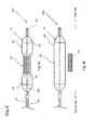
- Fig. 1 shows a schematic view of the catheter balloon that shoulder parts are spread according to the present invention.
- Fig. 1B shows a schematic view illustrating a state that a balloon part and a band part are disassembled.
- the word “spread” means that a balloon is developed merely by an increase in the internal pressure thereof but does not mean that the balloon itself is substantially expanded to be inflated.
- the word “expand” means that a band part is expanded to be made longer in diameter.
- the catheter balloon 10 comprises the balloon part 20 in a cylindrical shape made of non-expansive material or low-expansive material, and the band part 30 manufactured of stretching elastic body.
- the band part 30 has a shorter diameter than the spread diameter of the balloon part 20 in a state that a stretching force is not applied, and is wound around a middle position of the balloon part 20.
- the wound part by the band part 30 of a cylindrical part 21 of the balloon part 20 is not easily spread and is intentionally thinned down, and the band part 30 and a surrounding part thereof including the shoulder parts 23 are easily spread.
- the balloon part 20 is formed in a hollow bag shape, whose middle part is formed in a cylindrical shape, and whose both ends are tapered and formed in a conical shape.
- the balloon itself is formed non-expansive or low-expansive, and formed not to be inflated more than a certain level even if the inside is pressurized.
- Various kinds of well-known materials may be used for the balloon part 20; for example, nylon, polyvinyl chloride, polyethylene, polyurethane, polyether block amide copolymer, polyethylene telephthalate, olefinic polymer such as polypropylene, or copolymer consisting of a combination thereof, and others.
- non-expansive material or low-expansive material is recommended for the material forming the balloon part 20 itself.
- the balloon part 20 is not necessarily made of a single material, and may be a double layer consisting of different materials between an inner layer and an outer layer.
- the double layer balloon can be manufactured by shaping a tube manufactured by a double-layer extrusion molding. If a material compatible with a band part 30 that will be described later is used for the outer layer, for instance, it can be welded with the band part 30 so that they are easily fixed each other. By adopting the above-mentioned expansive percentage, over-spreading can be prevented.
- the balloon part 20 is formed in length from 30 mm to 80 mm, preferably from 50 to 70 mm, and the maximum spreading diameter is formed, preferably, from 10 mm to 25 mm. Depending on the size of the maximum spreading diameter, it can be applied to the openings of a body and other hollow organs in addition to artery and vein.
- the band part 30 is an expansive ring member, which is wound around the balloon part 20 to keep a part of the balloon part 20 less than the maximum spreading diameter at a certain pressure or less, and to be expanded at the certain pressure or more. Silicone, polyurethane, other elastomer-based polymer, and others, are used accordingly for materials, however, are not limited for the materials.
- the thickness of the band part 30 is manufactured from 20 ⁇ m to 100 ⁇ m, preferably from 50 to 70 ⁇ m, the width is manufactured from 3 to 30 mm, preferably 5 to 15 mm, and the diameter is manufactured from 3 mm to 20 mm. The diameter must be smaller than the maximum spreading diameter of the balloon part 20.
- the band part 30 keeps the diameter of a part of the balloon part 20 small.
- the spreading fluid is inserted into the balloon 20 at a predetermined pressure or less, specifically at a pressure permitting a waist part 30 to be spread or inflated, or lower, only the shoulder parts 23 are being spread while the waist part keeps the initial diameter thereof.
- the spread of the shoulder parts 23 and the other reaches into an equilibrium.
- the spread of the shoulder parts 23 causes the balloon 20, which has been folded up, to merely open, and thus the raw material itself of the balloon 20 is not expanded. Accordingly, the shoulder parts 23 are spread even at a relatively low pressure, for example, 0.05 atm or less.
- the raw material itself thereof needs to be expanded.
- the band part 30 is hardly expanded so that the band part 30 is kept to have the pre-expansion diameter. Consequently, as illustrated in Fig. 1A , at the fluid pressure or less which the band part 30 is expanded, it is formed in a so-called gourd shape as a whole, which is such a shape that the waist part 22 of the center of the balloon part 20 is narrow and the shoulder parts 23 are thick.
- the balloon part is easily arranged at a predetermined position so that the balloon part can be prevented from being freely shifted.
- the band part 30 arranged at the waist part 22 is expanded and increased in diameter, by means of injecting the spreading fluid to increase the internal pressure of the balloon part 20.
- the shoulder parts 23 of the balloon part 20 are non-expansive or low-expansive, and thus after the equilibrium state, the shoulder parts 23 are not spread or are slightly spread.
- the spreading fluid is further injected to increase the inner pressure of the balloon part 20 and expand the band part 30, and then the diameter of the balloon part 20 of the waist part 22 is being expanded.
- the waist part 22 of the balloon part 20 is spread to the same degree as the diameter of the shoulder parts 23. Because the balloon part 20 is non-expansive or low-expansive, the balloon part 20 is merely spread slightly more largely.
- the diameter is therefore possible to prevent the diameter from continuing to be inflated and being exploded easily such as an expansive balloon.
- the spreading pressure varies depending on the width, thickness, circumferential length or materials of the band part 30.
- the waist part 22 of the balloon part 20 may be adjusted to be slightly smaller in diameter than the shoulder parts 23. By adopting such an adjustment, it is possible to prevent the catheter balloon 10 from being freely shifted.
- the first manufacturing method is a method of manufacturing the balloon part 20 first, and then the band part 30 is attached with the balloon part 20.
- a method of manufacturing the balloon part 20 blow-forming, or stretching a tube manufactured by extrusion-forming by spreading it after heating the tube, may be used.
- a method of manufacturing the band part 30 is not particularly limited, as long as a strip-like expansive sheet is prepared. For example, stretching a tube prepared by extrusion-forming or by dipping may be adopted.
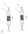
- the band part 30 is fixed onto the manufactured balloon part 20, the sheet-like band part 30 may be wrapped around the balloon part 20 and fixed, or the band part 30 preformed in a ring shape, as illustrated in Fig.
- Adhesion or welding can be selected as a fixing method of the band part 30 to the balloon part 20, however, not limited thereto.
- a compatible material each for the balloon part 20 and the band part 30.
- a compatible material may be used only for the outer layer of the balloon part 20.
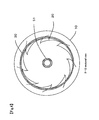
- the part 20 when the balloon part 20 is folded in a wing-like fashion (folded in a so-called umbrella shape), the part may be evenly-fixed to the front end or middle part of each wing. With this evenly-fixing method, the waist part 22 can be prevented from being unevenly spread as much as possible.
- the balloon part 20 fixed with the band part 30 is formed in a shape of which the waist part is thin and the shoulder parts 23 are thick like a gourd. Then it is completed, as illustrated in Fig. 3D , by folding in a winding manner the shoulder parts 23.
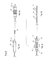
- the second manufacturing method is a method of forming both the balloon part 20 and band part 30 at the same time by blow-forming.
- a tube that is the material of the band part 30 is fixed around a parison 25 that is a tubular member before blow-forming.
- the band part 30 with the balloon part 20 is spread and extended by blow-forming, and as illustrated in Fig. 5C , is adhered together by heat at the time of the forming.
- the catheter balloon 10 can be manufactured only by one process. And it becomes easy for the band part 30 and the balloon part 20 to adhere together on the entire surfaces.
- the balloon part 20 manufactured in the above-mentioned manner is arranged at the distal end of a catheter main body to be a catheter.
- the catheter comprises a tip part 40 installed at the distal end of the catheter main body, an inner tube 50 having a guide wire lumen 51 connected with the tip part 40, the balloon part 20 arranged around the guide wire lumen 51, and an outer tube 60 having a spreading-fluid-injecting lumen 61 communicated with a balloon lumen 52 of the balloon part 20.
- the balloon part 20 is inflated by the spreading fluid through the spreading-fluid-injecting lumen 61.
- the catheter 100 is introduced through a thigh, upper arm artery or left subclavian artery.
- the catheter 100 is directly inserted into an aortic valve, so that the catheter 100 can be anteogradely inserted.
- the catheter 10 is detained in a valve cusp by an approach through a thigh. It is however needless to say that various detaining techniques are usable in accordance with the present invention.
- a puncture needle is stuck into a femoral artery (or an iliac artery inside the pelvis), which is near person's groin.
- a guide wire is inserted into the blood vessel. While the guide wire is being shifted along the blood vessel, the guide wire is slipped to be inserted into the blood vessel. The guide wire is passed through the aortic valve, and then indwelled. Thereafter, while the position of the guide wire is being monitored on a roentgenoscopic screen, the balloon 10 for catheter is retrogradely advanced to a target position.
- the catheter balloon 10 is detained to position the shoulder part 23 at the distal end side of the balloon 10 inside the left ventricule outflow tract, and position the waist part 22 at a valve cusp 91 of an aorta 90.
- a spreading fluid is introduced into the catheter balloon 10 to increase the pressure therein up to about 0.1 atm to 0.5 atm (the pressure in the balloon part 20 is made slightly higher than that outside the balloon).
- the balloon 20 is spread.
- the shoulder part 23 at the proximal side of the catheter and the shoulder part 23 at the distal side are spread while the waist part 22 is not spread to keep the diameter thereof small.
- the spreadable diameter of the shoulder parts 23 is selected into a size suitable for the valve cusp and the LVOT.
- the annulus is arranged to be sandwiched between the shoulder parts 23 at both the sides, so that the waist part 22 is arranged naturally at the valve cusp. Consequently, the balloon catheter 10 can be arranged at a desired position to be prevented from being freely shifted.
- the pressure inside the balloon part 20 is further increased, and the spreading fluid is introduced thereinto to give a pressure in the range of 0.5 atm to 5.0 atm, preferably 1.0 atm to 3.0 atm.
- the waist part 22 is spread to start pushing and moving the valve cusp outward.
- the spread of the waist part 22 pushes and moves the valve cusp to be opened, so that its calcified part is pulverized.
- the waist part 22 is spread into an outer diameter equivalent to that of the shoulder parts 23 which the band part 30 is not installed. Since the outer diameter of the waist part 22 is manufactured in the same size as that of the shoulder parts 23, it is not further spread and can be prevented completely from being excessively spread and damaging tissues around the balloon. Since the blockage of the blood flow is restricted for a short period of time, the balloon part 20 is deflated in a short period. When the balloon is spread, a contrast medium may be injected into the balloon part 20. In this way, it is possible to roentgenize the valve cusp in the state that the valve cusp is spread. Thus, the diameter of the spread valve cusp can be estimated.
- raw material and forms usable in the present invention are not limited to the present raw materials and form.
- the band parts 30 which are manufactured of polyurethane as an expansive material, 9 mm in the outer diameter, and 3mm, 5 mm, and 10 mm each in width is prepared and attached with the balloon parts 20 which are manufactured of low-expansive nylon and 15 mm in the outer diameter.
- a spreading fluid By injecting a spreading fluid into the balloon part 20, a change is measured in the inner pressure of the balloon part 20 and the outer diameter of the waist part 22 and shoulder parts 23 attached with the band part 30.
- the measurement of the outer diameter of each of the parts is started when the pressure begins rising inside the balloon part 20 after a spreading fluid is injected. Thereafter, the pressure and the outer diameter are measured each time a predetermined amount of the fluid is injected. Because the pressure is decreasing over time due to the creep phenomenon of the expansive material of the band part 30, the pressure in stable condition is recorded after a certain amount of time has been passed.
- the measurement result is as follows; with the 3 mm band width, 12.6 mm at the pressure of 0.032 MPa, and 14.3 mm at the pressure of 0.150MPa. With the 5 mm band width, 12.0 mm at the pressure of 0.024 MPa, 14.2 mm at the pressure of 0.1450 MPa, and 14.5 mm at the pressure of 0.180 MPa.
- a higher pressure than the expansivee strength of the band part 30 is necessary to expand the band part 30.
- this pressure can be changed depending on the material and size, etc. of the band part 30.
- the diameter of the shoulder parts 23 inflates slightly along with the pressure increase, however, non-expansive material is used and 10% or less of the inflation rate is achieved so that no big difference can be seen.
- the band part 30 cannot be the same as the outer diameter of the shoulder parts 23. It shows the slightly smaller diameter than that of the shoulder parts 23. As a result, an uneven shape of the balloon part 20 can prevent the balloon part 20 from slipping out of the valve and shifting freely.
- the catheter balloon 10 and the catheter 100 according to the present embodiment were described through an example of a transcatheter aortic valve replacement; however, they can be applied to the valvuloplasty of a stenotic aortic valve or pulmonary valve, or for dilating all stenotic constrictions in blood vessels. They also can be applied to the pre-spread of aortic valve cusp before placing a percutaneous aortic valve or any other artificial device used for aortic valve repair, replacement or transplantation.
- the applicable blood vessels include all blood vessels of the body, such as coronary arteries, peripheral arteries, veins, the gullet, the trachea, enteric blood vessels, the bile duct and the uriter, etc. of the body.
- the present invention is usable for intervention operations, especially for preventing a blood clot or debris from being scattered.
Landscapes
- Health & Medical Sciences (AREA)
- Heart & Thoracic Surgery (AREA)
- Life Sciences & Earth Sciences (AREA)
- Engineering & Computer Science (AREA)
- Biomedical Technology (AREA)
- Veterinary Medicine (AREA)
- Public Health (AREA)
- General Health & Medical Sciences (AREA)
- Animal Behavior & Ethology (AREA)
- Cardiology (AREA)
- Hematology (AREA)
- Anesthesiology (AREA)
- Pulmonology (AREA)
- Biophysics (AREA)
- Child & Adolescent Psychology (AREA)
- Manufacturing & Machinery (AREA)
- Oral & Maxillofacial Surgery (AREA)
- Transplantation (AREA)
- Vascular Medicine (AREA)
- Media Introduction/Drainage Providing Device (AREA)
Applications Claiming Priority (2)
| Application Number | Priority Date | Filing Date | Title |
|---|---|---|---|
| JP2012281704A JP2014124264A (ja) | 2012-12-25 | 2012-12-25 | カテーテル用バルーン、カテーテル及びカテーテル用バルーンを作製する方法 |
| PCT/JP2013/084196 WO2014103907A1 (fr) | 2012-12-25 | 2013-12-20 | Ballonnet de cathéter, cathéter et procédé de fabrication de ballonnet de cathéter |
Publications (2)
| Publication Number | Publication Date |
|---|---|
| EP2939701A1 true EP2939701A1 (fr) | 2015-11-04 |
| EP2939701A4 EP2939701A4 (fr) | 2016-10-12 |
Family
ID=51020992
Family Applications (1)
| Application Number | Title | Priority Date | Filing Date |
|---|---|---|---|
| EP13867162.3A Withdrawn EP2939701A4 (fr) | 2012-12-25 | 2013-12-20 | Ballonnet de cathéter, cathéter et procédé de fabrication de ballonnet de cathéter |
Country Status (6)
| Country | Link |
|---|---|
| US (1) | US20150174383A1 (fr) |
| EP (1) | EP2939701A4 (fr) |
| JP (1) | JP2014124264A (fr) |
| KR (1) | KR20150018887A (fr) |
| CN (1) | CN104507525A (fr) |
| WO (1) | WO2014103907A1 (fr) |
Families Citing this family (21)
| Publication number | Priority date | Publication date | Assignee | Title |
|---|---|---|---|---|
| JP2016168151A (ja) * | 2015-03-12 | 2016-09-23 | 株式会社東海メディカルプロダクツ | バルーンカテーテル |
| JP6227193B2 (ja) * | 2015-07-22 | 2017-11-08 | オリンパス株式会社 | 内視鏡処置具 |
| JP6227194B2 (ja) * | 2015-07-28 | 2017-11-08 | オリンパス株式会社 | 内視鏡用処置具 |
| KR101675698B1 (ko) * | 2015-10-30 | 2016-11-11 | 김주현 | 경막 협착 또는 추간공 협착 치료를 위한 의료장치 |
| JP2018538113A (ja) * | 2016-05-17 | 2018-12-27 | アスピセーフ ソリューションズ インコーポレイテッド | 拡張型挿管組立体 |
| JP6742885B2 (ja) * | 2016-10-27 | 2020-08-19 | テルモ株式会社 | バルーンカテーテル |
| CN108309383A (zh) * | 2018-01-23 | 2018-07-24 | 上海心玮医疗科技有限公司 | 一种用于血管内的医疗装置 |
| JPWO2019163502A1 (ja) * | 2018-02-26 | 2021-02-04 | 日本ゼオン株式会社 | 内視鏡用バルーンカテーテル |
| CN109907870A (zh) * | 2019-03-22 | 2019-06-21 | 佘彩芹 | 葫芦形空心避孕器 |
| CN111588970B (zh) * | 2020-05-29 | 2022-09-16 | 成都赛拉诺医疗科技有限公司 | 扩张球囊装置及扩张球囊装置的制作方法 |
| US20230390536A1 (en) * | 2020-11-13 | 2023-12-07 | K. Nagajyothi | Pressure induced deflatable foley's catheter |
| CN112827057B (zh) * | 2020-12-31 | 2023-04-14 | 先健科技(深圳)有限公司 | 球囊导管 |
| CN115253035B (zh) * | 2021-11-05 | 2024-02-23 | 首都医科大学宣武医院 | 用于切割斑块的介入手术的导管球囊及导管 |
| DE102022134125B4 (de) | 2021-12-23 | 2026-04-23 | Japan Lifeline Co., Ltd | Katheter, ballonexpansionsverfahren, ballonkompressionsverfahren |
| JP7566834B2 (ja) * | 2021-12-23 | 2024-10-15 | 日本ライフライン株式会社 | カテーテル |
| JP7587557B2 (ja) * | 2022-09-29 | 2024-11-20 | 日本ライフライン株式会社 | カテーテル挿入器具、カテーテル装置 |
| US20240181229A1 (en) | 2022-10-13 | 2024-06-06 | Japan Lifeline Co., Ltd. | Balloon catheter and balloon dilatation method |
| JP2024058580A (ja) * | 2022-10-13 | 2024-04-25 | 日本ライフライン株式会社 | バルーンカテーテルおよびバルーンの拡張方法 |
| DE102023136649B4 (de) * | 2023-12-22 | 2025-08-14 | Alexander Rübben | Ballonkatheter mit flexiblem Rückhalteelement mit beschichtetem und unbeschichtetem Abschnitt |
| WO2025259753A1 (fr) * | 2024-06-14 | 2025-12-18 | Edwards Lifesciences Corporation | Cathéters à ballonnet, ballonnets associés et procédés de formation de ballonnets |
| CN118902563B (zh) * | 2024-09-04 | 2025-03-18 | 北京美多康贸易有限公司 | 硬膜外介入装置、粘连松解方法和电极移动方法 |
Citations (2)
| Publication number | Priority date | Publication date | Assignee | Title |
|---|---|---|---|---|
| US4327736A (en) | 1979-11-20 | 1982-05-04 | Kanji Inoue | Balloon catheter |
| US20100094209A1 (en) | 2008-10-10 | 2010-04-15 | Intervalve, Inc. | Valvuloplasty Catheter And Methods |
Family Cites Families (6)
| Publication number | Priority date | Publication date | Assignee | Title |
|---|---|---|---|---|
| JPS54160090A (en) * | 1978-06-07 | 1979-12-18 | Kanji Inoue | Tearingganddopening device of isthmus by medical balloon catheter |
| US5545209A (en) * | 1993-09-30 | 1996-08-13 | Texas Petrodet, Inc. | Controlled deployment of a medical device |
| US7115138B2 (en) | 2002-09-04 | 2006-10-03 | Boston Scientific Scimed, Inc. | Sheath tip |
| US20060182873A1 (en) * | 2005-02-17 | 2006-08-17 | Klisch Leo M | Medical devices |
| WO2011028419A1 (fr) * | 2009-08-27 | 2011-03-10 | Boston Scientific Scimed, Inc. | Dispositifs de cathéter à ballonnet présentant une gaine enrobée de médicament |
| WO2012037162A1 (fr) * | 2010-09-13 | 2012-03-22 | Intervalve, Inc. | Cathéter de valvuloplastie positionnable |
-
2012
- 2012-12-25 JP JP2012281704A patent/JP2014124264A/ja active Pending
-
2013
- 2013-12-20 EP EP13867162.3A patent/EP2939701A4/fr not_active Withdrawn
- 2013-12-20 US US14/414,800 patent/US20150174383A1/en not_active Abandoned
- 2013-12-20 CN CN201380039868.6A patent/CN104507525A/zh active Pending
- 2013-12-20 KR KR1020157001003A patent/KR20150018887A/ko not_active Ceased
- 2013-12-20 WO PCT/JP2013/084196 patent/WO2014103907A1/fr not_active Ceased
Patent Citations (2)
| Publication number | Priority date | Publication date | Assignee | Title |
|---|---|---|---|---|
| US4327736A (en) | 1979-11-20 | 1982-05-04 | Kanji Inoue | Balloon catheter |
| US20100094209A1 (en) | 2008-10-10 | 2010-04-15 | Intervalve, Inc. | Valvuloplasty Catheter And Methods |
Non-Patent Citations (1)
| Title |
|---|
| See also references of WO2014103907A1 |
Also Published As
| Publication number | Publication date |
|---|---|
| CN104507525A (zh) | 2015-04-08 |
| EP2939701A4 (fr) | 2016-10-12 |
| WO2014103907A1 (fr) | 2014-07-03 |
| JP2014124264A (ja) | 2014-07-07 |
| KR20150018887A (ko) | 2015-02-24 |
| US20150174383A1 (en) | 2015-06-25 |
Similar Documents
| Publication | Publication Date | Title |
|---|---|---|
| EP2939701A1 (fr) | Ballonnet de cathéter, cathéter et procédé de fabrication de ballonnet de cathéter | |
| EP2939702A1 (fr) | Ballonnet de cathéter et cathéter | |
| JP7309643B2 (ja) | バルーンアセンブリ | |
| US9242081B2 (en) | Positionable valvuloplasty catheter | |
| US8486102B2 (en) | Valvuloplasty catheter | |
| US9907643B2 (en) | Systems for attaining a predetermined porosity of a vascular device | |
| US9504807B2 (en) | Valvuloplasty catheter and methods | |
| US6592568B2 (en) | Balloon assembly for stent delivery catheter | |
| EP2967947B1 (fr) | Ballonnet gonflable et couverture | |
| EP2833844B1 (fr) | Commande du taux de gonflage de ballonnet pendant le déploiement d'un échafaudage | |
| US9480823B2 (en) | Perfusion dilation catheter system and methods of use | |
| CN107261301A (zh) | 一种球囊导管及其制备方法和医疗装置 | |
| EP2349441A1 (fr) | Cathéter et procédés pour valvuloplastie | |
| HK1193777A (en) | Variable length catheter for drug delivery | |
| HK1206584B (en) | Control of balloon inflation rate during deployment of scaffold | |
| HK1193777B (en) | Variable length catheter for drug delivery | |
| HK1216078B (en) | Inflatable balloon and cover |
Legal Events
| Date | Code | Title | Description |
|---|---|---|---|
| PUAI | Public reference made under article 153(3) epc to a published international application that has entered the european phase |
Free format text: ORIGINAL CODE: 0009012 |
|
| 17P | Request for examination filed |
Effective date: 20150727 |
|
| AK | Designated contracting states |
Kind code of ref document: A1 Designated state(s): AL AT BE BG CH CY CZ DE DK EE ES FI FR GB GR HR HU IE IS IT LI LT LU LV MC MK MT NL NO PL PT RO RS SE SI SK SM TR |
|
| AX | Request for extension of the european patent |
Extension state: BA ME |
|
| DAX | Request for extension of the european patent (deleted) | ||
| TPAC | Observations by third parties |
Free format text: ORIGINAL CODE: EPIDOSNTIPA |
|
| A4 | Supplementary search report drawn up and despatched |
Effective date: 20160913 |
|
| RIC1 | Information provided on ipc code assigned before grant |
Ipc: A61M 25/10 20060101AFI20160907BHEP |
|
| STAA | Information on the status of an ep patent application or granted ep patent |
Free format text: STATUS: THE APPLICATION IS DEEMED TO BE WITHDRAWN |
|
| 18D | Application deemed to be withdrawn |
Effective date: 20170411 |