EP2939708A1 - Dispositif de mesure de la répartition de doses - Google Patents
Dispositif de mesure de la répartition de doses Download PDFInfo
- Publication number
- EP2939708A1 EP2939708A1 EP12891049.4A EP12891049A EP2939708A1 EP 2939708 A1 EP2939708 A1 EP 2939708A1 EP 12891049 A EP12891049 A EP 12891049A EP 2939708 A1 EP2939708 A1 EP 2939708A1
- Authority
- EP
- European Patent Office
- Prior art keywords
- irradiation
- dose
- dose distribution
- particle beam
- camera
- Prior art date
- Legal status (The legal status is an assumption and is not a legal conclusion. Google has not performed a legal analysis and makes no representation as to the accuracy of the status listed.)
- Withdrawn
Links
Images






Classifications
-
- A—HUMAN NECESSITIES
- A61—MEDICAL OR VETERINARY SCIENCE; HYGIENE
- A61N—ELECTROTHERAPY; MAGNETOTHERAPY; RADIATION THERAPY; ULTRASOUND THERAPY
- A61N5/00—Radiation therapy
- A61N5/10—X-ray therapy; Gamma-ray therapy; Particle-irradiation therapy
- A61N5/1048—Monitoring, verifying, controlling systems and methods
- A61N5/1075—Monitoring, verifying, controlling systems and methods for testing, calibrating, or quality assurance of the radiation treatment apparatus
-
- G—PHYSICS
- G01—MEASURING; TESTING
- G01T—MEASUREMENT OF NUCLEAR OR X-RADIATION
- G01T1/00—Measuring X-radiation, gamma radiation, corpuscular radiation, or cosmic radiation
- G01T1/02—Dosimeters
- G01T1/10—Luminescent dosimeters
- G01T1/105—Read-out devices
-
- G—PHYSICS
- G01—MEASURING; TESTING
- G01T—MEASUREMENT OF NUCLEAR OR X-RADIATION
- G01T1/00—Measuring X-radiation, gamma radiation, corpuscular radiation, or cosmic radiation
- G01T1/16—Measuring radiation intensity
- G01T1/20—Measuring radiation intensity with scintillation detectors
- G01T1/204—Measuring radiation intensity with scintillation detectors the detector being a liquid
-
- A—HUMAN NECESSITIES
- A61—MEDICAL OR VETERINARY SCIENCE; HYGIENE
- A61N—ELECTROTHERAPY; MAGNETOTHERAPY; RADIATION THERAPY; ULTRASOUND THERAPY
- A61N5/00—Radiation therapy
- A61N5/10—X-ray therapy; Gamma-ray therapy; Particle-irradiation therapy
- A61N5/1048—Monitoring, verifying, controlling systems and methods
- A61N5/1075—Monitoring, verifying, controlling systems and methods for testing, calibrating, or quality assurance of the radiation treatment apparatus
- A61N2005/1076—Monitoring, verifying, controlling systems and methods for testing, calibrating, or quality assurance of the radiation treatment apparatus using a dummy object placed in the radiation field, e.g. phantom
-
- A—HUMAN NECESSITIES
- A61—MEDICAL OR VETERINARY SCIENCE; HYGIENE
- A61N—ELECTROTHERAPY; MAGNETOTHERAPY; RADIATION THERAPY; ULTRASOUND THERAPY
- A61N5/00—Radiation therapy
- A61N5/10—X-ray therapy; Gamma-ray therapy; Particle-irradiation therapy
- A61N2005/1085—X-ray therapy; Gamma-ray therapy; Particle-irradiation therapy characterised by the type of particles applied to the patient
- A61N2005/1087—Ions; Protons
Definitions
- the present invention relates to a dose distribution measurement device for measuring a dose distribution formed by a particle beam that is used in, for example, particle beam therapies for cancers.
- a therapy radiation beam such as an X-ray, an electron beam, and a particle beam
- Patent Document 1 using a water tank mimicking a human body and an ionization chamber equipped with an actuator for changing the chamber position in the water, a dose distribution formed in the water by irradiation with a radiation beam is measured by scanning the ionization chamber. For that reason, a lot of time and effort is needed for only one dose distribution measurement.
- Patent Document 2 discloses a technology in which a substance that emits fluorescence when excited by radiation is contained in a solid phantom of high visible-light transparency to measure a fluorescence intensity by converting the light emission induced by the radiation into electrical signals using a CCD camera or the like.
- Patent Document 3 discloses a particle-beam dose-distribution measurement device including a scintillator unit composed of a scintillation liquid that emits light when irradiated with a proton beam and an imaging unit composed of a CCD camera for taking an image of the scintillator unit in a direction perpendicular to the incident direction of the proton beam, thereby to simultaneously measure scintillations in a plurality of horizontal cross-sectional planes along the incident direction of the particle beam to reconstructed a two-dimensional distribution for each cross-sectional plane and finally to obtain a three-dimensional distribution.
- the scanning irradiation method is a method of forming a two-dimensional irradiation distribution perpendicular to the beam traveling direction by shifting a fine particle beam, which is called a pencil beam, in the two-dimensional directions perpendicular thereto.
- the irradiation position in the beam traveling direction is varied by changing the energy of the particle beam.
- a three-dimensional irradiation field is formed by shifting the pencil beam and changing its energy as described above.
- Patent Documents 1 to 3 which are for measuring a dose distribution when the irradiation position does not vary with time, cannot be directly applied to measurement of a dose distribution formed by the scanning irradiation method, or need a significant time when trying to measure a dose distribution formed by the scanning irradiation method.
- the present invention has been made to overcome such an above-described problem, and aims at providing a particle-beam dose-distribution measurement device that is capable of measuring, with a simple configuration and in a short time, a particle beam dose distribution formed by a scanning irradiation method.
- the present invention provides a dose distribution measurement device for measuring an irradiation dose distribution to be generated when an irradiation-related device for irradiating an irradiation target with a particle beam as a pencil beam irradiates a three-dimensional target region with the particle beam by scanning, every time an energy level of the particle beam is changed, the particle beam over a two dimensional region of the irradiation target at a depth position corresponding to the energy level with repetition of staying and shifting of the particle beam in a two-dimensional direction perpendicular to the beam traveling direction.
- the dose distribution measurement device includes:
- a dose distribution measurement device can be provided that is capable of measuring a dose distribution with a simple configuration and in a short time.
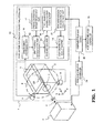
- FIG. 1 is a block diagram schematically showing a configuration of a particle beam irradiation system including a dose distribution measurement device 1 according to Embodiment 1 of the present invention.
- a particle beam 4 is emitted from an irradiation-related device 2 toward a water phantom 3 constituted with a water tank.
- the water phantom 3 is filled with a fluorescent substance containing liquid 5 (generally referred to as a liquid scintillator) that emits light on absorbing the particle beam.
- a fluorescent substance containing liquid 5 generally referred to as a liquid scintillator
- the wall of the water phantom 3 is formed of a transparent material such as an acrylic resin that transmits light.
- an incident window 6 made of a similar material such as an acrylic resin that little absorbs the particle beam.
- the incident window 6 is sometimes formed thinner than the other portion.
- Two cameras of a camera 7 and a camera 8 are provided around the water phantom 3. The two cameras are arranged, for example, on a circle C, which is in a plane perpendicular to the irradiation center axis CA of the particle beam 4 and centered on the irradiation center axis CA, to take an image whose center is on the irradiation center axis CA.
- a dose distribution calculation and evaluation unit 10 calculates and evaluates a dose distribution from the camera images taken with the cameras 7 and 8.
- the dose distribution calculation and evaluation unit 10 includes a camera image processing part 11 for processing the camera images; a spot position determination part 12 for determining a spot position from a camera image processed by the camera image processing part 11 using camera calibration parameters stored in a camera calibration-parameter storage part 17.
- the dose distribution calculation and evaluation unit 10 further includes a dose addition part 13 for calculating and adding a dose at each of spot positions using a pencil beam dose distribution stored in a pencil-beam dose-distribution data storage part 16; and a dose distribution evaluation part 14 for comparing a measured dose distribution that is a result added by the dose addition part 13 with irradiation-region dose distribution data that is planned in a treatment planning device 20 and stored in an irradiation-region dose-distribution data storage part 15 for storing the irradiation-region dose distribution data, to evaluate the measured dose distribution.
- a particle beam 4 which is called a fine pencil beam, is shifted in the two-dimensional directions perpendicular to the beam traveling direction by the irradiation-related device 2 to form a two-dimensional irradiation distribution perpendicular to the beam traveling direction.
- the beam traveling direction is defined as a Z-direction and two directions perpendicular to the Z-direction, i.e., directions in which the beam is shifted are defined as an X-direction and a Y-direction.
- the irradiation-related device 2 includes an X-direction deflection electromagnet and a Y-direction deflection electromagnet for deflecting the particle beam 4 in the X-direction and the Y-direction, respectively.
- the particle beam 4 is emitted with repetition of shifting and staying by the irradiation-related device 2. That is, the particle beam 4 stays at an irradiation position (hereinafter referred to as a spot position) and when the irradiation dose at the spot position reaches a planned irradiation dose, the particle beam 4 is shifted to the next spot position and is emitted until the irradiation dose at the next spot position reaches its planned irradiation dose.
- a spot position an irradiation position
- Repetition of the shifting and staying for an energy level of the particle beam 4 forms a planned irradiation dose distribution, i.e., a two-dimensional irradiation dose distribution in an irradiation region at a Bragg peak position corresponding to the energy level, i.e., at a depth position in the beam traveling direction. Since the irradiation depth is varied by changing the energy level of the particle beam, the energy level of the particle beam is changed to form a planned two-dimensional irradiation dose distribution in an irradiation region at another depth position.
- a planned irradiation dose distribution i.e., a two-dimensional irradiation dose distribution in an irradiation region at a Bragg peak position corresponding to the energy level, i.e., at a depth position in the beam traveling direction. Since the irradiation depth is varied by changing the energy level of the particle beam, the energy level of the particle beam is changed to form a planned two-dimensional irradiation
- a planned irradiation dose distribution is finally formed in a three-dimensional irradiation region by forming two-dimensional irradiation dose distributions with repetition of shifting and staying of the particle beam 4 for each different energy level.
- Such an irradiation method described above is here referred to as a spot scanning irradiation method.
- the treatment planning device 20 calculates control parameters for an irradiation-related controller 21 to control the irradiation-related device 2 and control parameters for an accelerator-related controller 22 to control a not-shown accelerator, and transmits these control parameters to the irradiation-related controller 21 and the accelerator-related controller 22.
- the dose distribution measurement device 1 is used in advance to the therapy in order to check whether the planned dose distribution is formed when the irradiation is performed in accordance with these control parameters.
- a dose distribution measuring method using the dose distribution measurement device 1 according to Embodiment 1 of the present invention will be described with reference to FIGS. 1 to 5 .
- Dose distribution characteristics of a pencil beam are measured first before a three-dimensional dose distribution is measured by the dose distribution measurement device 1.
- the dose distribution characteristics of the pencil beam is measured as a percent depth dose (PDD), which is a distribution in the Z-direction, and as an off center axis ratio (OCR), which is a distribution in the X-Y plane.
- PDD percent depth dose
- OCR off center axis ratio
- the OCR and the PDD can be measured with instruments such as a heretofore known thimble dosimeter and an Advanced Markus®, respectively, or also measured by a method later-described in Embodiment 5.
- Examples of a PDD and an OCR are respectively shown in the graphs (A) and (B) of FIG. 2 . These PDD and OCR are measured for each energy level of the particle beam, and stored in the pencil-beam dose- distribution data storage part 16 of the dose distribution calculation and evaluation unit 10.
- the water phantom 3 is irradiated with the particle beam 4 by the spot scanning irradiation method. Specifically, each spot is irradiated with the particle beam 4 by controlling the accelerator and the irradiation-related device 2 in accordance with the control parameters for each spot position, of the accelerator-related controller 22 and the irradiation-related controller 21.
- the particle beam 4 is scanned with repetition of staying and shifting in the two-dimensional directions perpendicular to the traveling direction over a two-dimensional irradiation region in the water phantom at a depth position corresponding to the energy level.
- a three-dimensional irradiation region is thereby irradiated with the particle beam 4.
- an image of light emission of the fluorescent substance containing liquid 5 is taken for each irradiation spot position with the cameras 7 and 8. The highest intensity point in the taken image is extracted for each spot position.
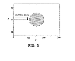
- plotting highest intensity points at all spot positions by extracting the highest intensity point in the image taken for each spot position with the camera 7, data as shown in FIG. 3 is obtained.
- a three-dimensional dose distribution that is obtained by the spot irradiation is calculated for each spot position using the PDD and the OCR data stored in the pencil-beam dose- distribution data storage part 16.
- An integrated three-dimensional irradiation distribution can be obtained by integrating the three-dimensional dose distributions at all spot positions.
- a calibration point whose three-dimensional coordinate position is given is implanted in the water phantom so that the calibration point can be positioned at the isocenter of a therapeutic coordinate using a laser pointer or the like in the treatment room.
- the external and internal parameters of each camera are calculated using the calibration point in each camera image.
- the calculated external and internal calibration parameters of each camera are stored in the camera calibration-parameter storage part 17.
- the above measurement method is explained with reference to the flow diagram of FIG. 4 .
- the PDD and the OCR of the pencil beam are measured in advance for each particle-beam energy level, to be stored in the pencil-beam dose-distribution data storage part 16 of the dose distribution calculation and evaluation unit 10 (Step ST1).
- i 1 to obtain measured irradiation dose distribution data at the first spot position (Step ST2).
- the spot position determination part 12 determines the highest intensity position as a three-dimensional position of the spot and calculates a peak dose from the intensity (Step ST4). In determining the three-dimensional position, the camera calibration parameters of each camera stored in the camera calibration-parameter storage part 17 are used.
- the spot position determination part 12 determines the highest intensity position as a three-dimensional position of the spot and calculates the peak dose from the intensity (Step ST4).
- FIG. 5 is a graph showing a two-dimensional distribution in the X- and the Z-directions at a Y-position near the center, that is, a distribution chart of two-and-half--dimensions.
- a three-dimensional irradiation dose distribution such as having point-by-point values in the X, Y, Z three-dimensional volume is obtained.
- the dose distribution evaluation part 14 compares the measured three-dimensional irradiation dose distribution thus obtained with a three-dimensional irradiation dose distribution set in a treatment plan and evaluates the measured dose distribution (Step ST8).
- the dose distribution set in the treatment plan is stored in advance in the irradiation-region dose-distribution data storage part 15 of the dose distribution calculation and evaluation unit 10 from the treatment planning device. Evaluation to what degree the measured irradiation dose distribution conforms to the irradiation dose distribution set in the treatment plan can be performed using a known index such as a gamma index.
- the dose distribution measurement device is capable of easily measuring a dose distribution of a spot scanning irradiation by determining spot positions from an image obtained by taking light emission of the water phantom 3 induced by irradiation of each spot with the two cameras 7 and 8 arranged on the circle C centered on the irradiation center axis CA and using the in advance measured PDD and OCR data of a pencil beam. It is desirable to arrange the two cameras at positions for their imaging angles to be perpendicular to each other.
- the two cameras are not necessarily arranged at the perpendicular positions because determination of camera calibration parameters corresponding to the camera arrangement permits a spot position to be determined from camera images.
- FIG. 6 is a block diagram schematically showing a configuration of a particle beam irradiation system that includes a dose distribution measurement device 100 according to Embodiment 2 of the present invention.
- the same reference numerals as those in FIG. 1 designate the same or equivalent components.
- an OCR measuring camera 9 is added to the configuration of the dose distribution measurement device 1 of Embodiment 1.
- the OCR measuring camera 9 is disposed outside the water phantom 3 and toward the opposite side of the incident window 6 of the water phantom 3 to take an image toward the water phantom 3. The image is taken every time a spot is irradiated, thus obtaining an image corresponding to the OCR for each spot irradiation.
- An OCR distribution calculation part 18 in a dose distribution calculation and evaluation unit 110 calculates OCR data for each spot irradiation from these images.
- the beam diameter is calculated from the camera images and the beam distribution may be assumed to have, for example, a Gaussian distribution.
- the dose addition part 13 calculates and adds, in the step ST5 described in Embodiment 1, an irradiation dose distribution having a peak at the spot position i determined by the spot position determination part 12 using the OCR data calculated by the OCR distribution calculation part 18 and the PDD data stored in the pencil-beam dose-distribution data storage part 16.
- Embodiment 2 there is no need to measure and store in advance the OCR of the pencil beam, and an OCR at the time of actual irradiation is measured to be used for calculation of a dose distribution, thus measuring a dose distribution with higher accuracy.
- FIG. 7 is a block diagram schematically showing a configuration of a particle beam irradiation system that includes a dose distribution measurement device 200 according to Embodiment 3 of the present invention.
- the same reference numerals as those in FIG. 1 designate the same or equivalent components.
- one camera 70 is provided outside the water phantom 3 and disposed, for example, on a circle C, which is in a plane perpendicular to the irradiation center axis CA of the particle beam 4 and centered on the irradiation center axis CA, to take an image whose center is on the irradiation center axis CA.
- FIG. 8 shows an operational flow of the dose distribution measurement device 200 according to Embodiment 3.
- the water phantom 3 is irradiated with the particle beam 4 by the spot scanning irradiation method (Step ST11) and then an image of light emission of the fluorescent substance containing liquid 5 is taken with the camera 70 with a continuous exposure during the irradiation (Step ST12).
- the light emission is recorded as integrated values in a camera image processing part 211 in a dose distribution calculation and evaluation unit 210.
- the image to be recorded may be an image that expresses the light intensity by a grey scale or by iso-intensity curves that connect points of the same light intensity.
- the recorded image is not the dose distribution itself but is values integrated temporally and spatially in the optical axis direction of the camera.
- an image prediction part 30 simulates light emission amounts of the water phantom 3 induced by the dose distribution using irradiation-region dose distribution data set in the treatment planning device 20 and stored in the irradiation-region dose-distribution data storage part 15, and predicts an image as spatially and temporally integrated values that would be taken at the position of the camera 70 from the simulated light emission amounts, to stores the predicted image. Since the light emission of the fluorescent substance containing liquid 5 is almost nonlinear to an irradiation dose, it is preferable to take the nonlinearity into account in the simulation.
- a dose distribution evaluation part 214 compares the dose distribution at the time of actual irradiation with the dose distribution set in the treatment planning device 20 and evaluates the actual dose distribution by comparing the taken image recorded in the camera image processing part 211 with the predicted image stored in the image prediction part 30 and evaluating the taken image (Step ST13).
- the dose distribution measurement device is not capable of measuring directly a dose distribution itself, but is capable of comparing with the one camera configuration an actual irradiation dose distribution with a dose distribution set in the treatment planning device with the one camera configuration, thereby evaluating indirectly the actual irradiation dose distribution.
- FIG. 9 is a block diagram schematically showing a configuration of a particle beam irradiation system that includes a dose distribution measurement device 300 according to Embodiment 4 of the present invention.
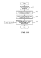
- FIG. 10 is a flow diagram showing an operation of the dose distribution measurement device according to Embodiment 4.
- the same reference numerals as those in FIG. 7 designate the same or equivalent components.
- the one camera 70 is provided outside the water phantom 3 and disposed, for example, on a circle C, which is in a plane perpendicular to the irradiation center axis CA of the particle beam 4 and centered on the irradiation center axis CA, to take an image whose center is on the irradiation center axis CA, as with Embodiment 3.
- Embodiment 4 similarly to Embodiment 3, the water phantom 3 is irradiated with the particle beam 4 by the spot scanning irradiation method (Step ST11) and then an image of light emission of the fluorescent substance containing liquid 5 is taken with the camera 70 with a continuous exposure during the irradiation (Step ST12), thereby to record the light emission as as integrated values in a camera image processing part 311 in a dose distribution calculation and evaluation unit 310.
- the recorded image is not the dose distribution itself but is the values integrated temporally and spatially in the optical axis direction of the camera.
- the image is recorded as data expressing, for example, iso-curves of the light intensity as FIG. 11 .
- a one-dimensional light-intensity distribution calculation part 319 of the dose distribution calculation and evaluation unit 310 extracts from the image a one-dimensional light intensity distribution in a cross section A parallel to the irradiation center axis CA and a one-dimensional light intensity distribution in a cross section B perpendicular to the irradiation center axis CA (Step ST14).
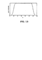
- FIGS. 12 and 13 Examples of the extracted light intensity distributions are shown in FIGS. 12 and 13 .
- FIG. 12 is an example of a one-dimensional, i.e., Z-directional light intensity distribution in the cross section A parallel to the irradiation center axis CA
- FIG. 13 is an example of a one-dimensional, i.e., X-directional light intensity distribution in the cross section B perpendicular the irradiation center axis CA.
- an image prediction part 315 simulates light emission amounts of the water phantom 3 induced by the dose distribution using irradiation-region dose distribution data set in the treatment planning device 20 and stored in the irradiation-region dose-distribution data storage part 15, and predicts an image as spatially and temporally integrated values that would be taken at the position of the camera 70 from the simulated light emission amounts, to extract, from the predicted image, one-dimensional light intensity distributions in a cross section A parallel to the irradiation center axis CA and in a cross section B perpendicular to the irradiation center axis CA.
- the dose distribution evaluation part 314 evaluates the irradiation dose distribution by comparing the one-dimensional light intensity distributions extracted, from the taken image, by the one-dimensional light intensity distribution calculation part 319 with the one-dimensional light intensity distributions extracted, from the predicted image, by the image prediction part 315 (Step ST15).
- FIG. 14 is an operational flow diagram of a dose distribution measurement device according to Embodiment 5 of the present invention.
- the dose distribution measurement device according to Embodiment 5 can obtain pencil beam source data of the particle beam 4 with the configuration of the dose distribution measurement device 300 shown in FIG. 9 , which is the same configuration as Embodiment 4, by irradiating the water phantom 3 for a short time without shifting the particle beam 4 as the pencil beam (Step ST21) and then by taking an image of light emission induced by the pencil beam with the camera 70 (Step ST22).
- one-dimensional light intensity distribution in the Z-direction and a one-dimensional light intensity distribution in the X-direction calculated by a one-dimensional light intensity distribution calculation part 319 are a distribution corresponding to a PDD and a distribution corresponding to an X-directional OCR, respectively, of the source beam.
- the dose distribution evaluation part 314 extract the PDD and the OCR data of the source beam from one-dimensional intensity distributions calculated by the one-dimensional light intensity distribution calculation part 319 (Step ST24).
- the first situation is measurements for registering source beam data for a treatment plan.
- a thimble dosimeter or the like is used for the OCR measurement.
- a Bragg Peak chamber or the like is used for the PDD measurement.
- the other application is distribution measurements for validating in advance whether an irradiation dose of a patient is in accordance with that simulated in the treatment plan.
- the OCR is often measured with a thimble dosimeter or the like
- the PDD is often measured with an Advanced Markus® or the like.
- each Embodiment may be freely combined and/or appropriately modified and/or omitted within the scope and spirit of the invention.
Landscapes
- Health & Medical Sciences (AREA)
- Life Sciences & Earth Sciences (AREA)
- Engineering & Computer Science (AREA)
- Biomedical Technology (AREA)
- Physics & Mathematics (AREA)
- Spectroscopy & Molecular Physics (AREA)
- Molecular Biology (AREA)
- High Energy & Nuclear Physics (AREA)
- General Physics & Mathematics (AREA)
- Nuclear Medicine, Radiotherapy & Molecular Imaging (AREA)
- Veterinary Medicine (AREA)
- Public Health (AREA)
- General Health & Medical Sciences (AREA)
- Animal Behavior & Ethology (AREA)
- Radiology & Medical Imaging (AREA)
- Pathology (AREA)
- Radiation-Therapy Devices (AREA)
- Measurement Of Radiation (AREA)
Applications Claiming Priority (1)
| Application Number | Priority Date | Filing Date | Title |
|---|---|---|---|
| PCT/JP2012/083641 WO2014102929A1 (fr) | 2012-12-26 | 2012-12-26 | Dispositif de mesure de la répartition de doses |
Publications (2)
| Publication Number | Publication Date |
|---|---|
| EP2939708A1 true EP2939708A1 (fr) | 2015-11-04 |
| EP2939708A4 EP2939708A4 (fr) | 2016-08-10 |
Family
ID=51020088
Family Applications (1)
| Application Number | Title | Priority Date | Filing Date |
|---|---|---|---|
| EP12891049.4A Withdrawn EP2939708A4 (fr) | 2012-12-26 | 2012-12-26 | Dispositif de mesure de la répartition de doses |
Country Status (6)
| Country | Link |
|---|---|
| US (1) | US20150306427A1 (fr) |
| EP (1) | EP2939708A4 (fr) |
| JP (1) | JP5918865B2 (fr) |
| CN (1) | CN104870054B (fr) |
| TW (1) | TWI463163B (fr) |
| WO (1) | WO2014102929A1 (fr) |
Cited By (2)
| Publication number | Priority date | Publication date | Assignee | Title |
|---|---|---|---|---|
| WO2018217763A1 (fr) * | 2017-05-26 | 2018-11-29 | Accuray Incorporated | Étalonnage et vérification de position de faisceau de traitement basé sur un rayonnement |
| WO2020020840A1 (fr) * | 2018-07-23 | 2020-01-30 | Ion Beam Applications S.A. | Détecteurs scintillateurs pour l'assurance qualité d'un faisceau de photons thérapeutique |
Families Citing this family (22)
| Publication number | Priority date | Publication date | Assignee | Title |
|---|---|---|---|---|
| JP6062073B2 (ja) * | 2014-01-10 | 2017-01-18 | 三菱電機株式会社 | 粒子線照射装置 |
| GB2530790B (en) * | 2014-10-02 | 2016-10-19 | Vision Rt Ltd | Method of calibrating a patient monitoring system for use with a radiotherapy treatment apparatus |
| NL2014012B1 (en) | 2014-12-18 | 2016-10-12 | Univ Groningen | Imaging method and system for verification of a treatment plan in hadron therapy. |
| JP6493859B2 (ja) * | 2015-04-09 | 2019-04-03 | 公益財団法人若狭湾エネルギー研究センター | 放射線モニタリングシステム |
| JP6588980B2 (ja) * | 2015-07-01 | 2019-10-09 | 株式会社日立製作所 | 線量分布演算装置、粒子線治療装置、及び線量分布演算方法 |
| EP3394639B1 (fr) * | 2015-12-23 | 2022-10-19 | Agfa Nv | Dosimètre de rayonnement |
| US11480692B2 (en) * | 2017-02-03 | 2022-10-25 | The University Of Liverpool | Phantom |
| GB2565119A (en) * | 2017-08-02 | 2019-02-06 | Vision Rt Ltd | Method of calibrating a patient monitoring system for use with a radiotherapy treatment apparatus |
| CN107875524B (zh) * | 2017-11-10 | 2020-06-12 | 上海联影医疗科技有限公司 | 放射治疗系统、模体以及等中心校准方法 |
| GB2571122B (en) * | 2018-02-19 | 2020-04-22 | Elekta ltd | Water tank apparatus |
| CN110354402B (zh) * | 2018-04-28 | 2021-05-11 | 北京铭杰医疗科技有限公司 | 电子束剂量测量系统及检测方法 |
| JP7125109B2 (ja) * | 2018-09-21 | 2022-08-24 | 国立研究開発法人量子科学技術研究開発機構 | データ分析装置、比較表示装置、治療計画データ編集装置、線量分布測定方法、プログラムおよび線量分布測定装置 |
| CN109394215B (zh) * | 2018-11-16 | 2022-04-29 | 上海京悦机械有限公司 | 一种医疗器械模体及夹具及加工工艺 |
| DE102020200400B4 (de) | 2019-02-14 | 2021-10-28 | Siemens Healthcare Gmbh | Kontrolliertes Bestrahlen eines Objekts |
| KR102232327B1 (ko) * | 2019-03-14 | 2021-03-29 | 충남대학교산학협력단 | 근접방사선원의 방사선량분포 측정장치 및 그 측정 방법 |
| CN111973892B (zh) * | 2019-05-23 | 2022-07-08 | 千才生医股份有限公司 | 用于放射治疗的笔尖式质子束扫描系统剂量分布重建方法 |
| CN110652661B (zh) * | 2019-09-30 | 2021-03-26 | 中北大学 | 一种卷积叠加剂量计算系统 |
| IT202000007780A1 (it) * | 2020-04-14 | 2021-10-14 | Istituto Naz Di Fisica Nucleare I N F N | Rivelatore per dosimetria in carburo di silicio |
| CN112083467B (zh) * | 2020-09-28 | 2022-05-31 | 中国科学院近代物理研究所 | 一种粒子治疗装置的三维剂量测量探测系统 |
| CN113406686A (zh) * | 2021-06-16 | 2021-09-17 | 中国科学院近代物理研究所 | 一种离子束三维剂量分布探测装置及方法 |
| CN118732007B (zh) * | 2024-06-09 | 2025-10-03 | 中国科学技术大学 | 一种磁场中质子放射剂量的计算方法 |
| CN121741801A (zh) * | 2024-09-25 | 2026-03-27 | 广东省新兴激光等离子体技术研究院 | 一种基于水电离的三维辐射剂量测试方法及辐射剂量计 |
Family Cites Families (51)
| Publication number | Priority date | Publication date | Assignee | Title |
|---|---|---|---|---|
| US5596653A (en) * | 1991-04-09 | 1997-01-21 | Mitsubishi Denki Kabushiki Kaisha | Radiation therapy treatment planning system |
| JP3841898B2 (ja) * | 1996-11-21 | 2006-11-08 | 三菱電機株式会社 | 深部線量測定装置 |
| EP0897731A4 (fr) * | 1996-11-26 | 2003-07-30 | Mitsubishi Electric Corp | Procede d'obtention de rayonnement d'energie |
| US6025717A (en) * | 1997-06-23 | 2000-02-15 | Fonar Corporation | Diagnostic simulator for MRI |
| DE19907774A1 (de) * | 1999-02-19 | 2000-08-31 | Schwerionenforsch Gmbh | Verfahren zum Verifizieren der berechneten Bestrahlungsdosis eines Ionenstrahl-Therapiesystems |
| JP2001346894A (ja) * | 2000-06-08 | 2001-12-18 | Mitsubishi Electric Corp | 線量分布測定装置 |
| AU2001294604A1 (en) * | 2000-09-22 | 2002-04-02 | Numerix Llc | Improved radiation therapy treatment method |
| US20020122117A1 (en) * | 2000-12-26 | 2002-09-05 | Masamichi Nakagawa | Camera device, camera system and image processing method |
| WO2002096096A1 (fr) * | 2001-05-16 | 2002-11-28 | Zaxel Systems, Inc. | Systeme et procede de reprise instantanee 3d |
| JP2002360715A (ja) * | 2001-06-08 | 2002-12-17 | Mitsubishi Electric Corp | 線量分布測定装置および線量分布測定システム |
| JP3839687B2 (ja) | 2001-08-07 | 2006-11-01 | 三菱電機株式会社 | 水ファントム型線量分布測定装置 |
| JP2003079755A (ja) | 2001-09-12 | 2003-03-18 | Wakasawan Energ Kenkyu Center | 光ctによる粒子線線量分布測定装置および方法 |
| JP4146648B2 (ja) * | 2002-02-14 | 2008-09-10 | 三菱電機株式会社 | 吸収線量分布測定装置 |
| JP4147059B2 (ja) * | 2002-07-03 | 2008-09-10 | 株式会社トプコン | キャリブレーション用データ測定装置、測定方法及び測定プログラム、並びにコンピュータ読取可能な記録媒体、画像データ処理装置 |
| US7307654B2 (en) * | 2002-10-31 | 2007-12-11 | Hewlett-Packard Development Company, L.P. | Image capture and viewing system and method for generating a synthesized image |
| JP2004321408A (ja) * | 2003-04-23 | 2004-11-18 | Mitsubishi Electric Corp | 放射線照射装置および放射線照射方法 |
| CA2574675C (fr) * | 2004-07-20 | 2015-11-24 | Resonant Medical Inc. | Calibrage de dispositifs d'imagerie |
| US7208748B2 (en) * | 2004-07-21 | 2007-04-24 | Still River Systems, Inc. | Programmable particle scatterer for radiation therapy beam formation |
| JP4585815B2 (ja) * | 2004-09-03 | 2010-11-24 | キヤノン株式会社 | 情報処理装置、撮影システム、吸収係数補正方法、及びコンピュータプログラム |
| DE112005002171B4 (de) * | 2005-02-04 | 2009-11-12 | Mitsubishi Denki K.K. | Teilchenstrahl-Bestrahlungsverfahren und dafür verwendete Teilchenstrahl-Bestrahlungsvorrichtung |
| US7629598B2 (en) * | 2005-02-04 | 2009-12-08 | Mitsubishi Denki Kabushiki Kaisha | Particle beam irradiation method using depth and lateral direction irradiation field spread and particle beam irradiation apparatus used for the same |
| US20070249925A1 (en) * | 2005-08-29 | 2007-10-25 | Martin Hoheisel | X-Ray Diagnostic Device for Mammography |
| US7450687B2 (en) * | 2005-09-29 | 2008-11-11 | University Of Medicine And Dentistry Of New Jersey | Method for verification of intensity modulated radiation therapy |
| JP4022249B2 (ja) * | 2005-12-28 | 2007-12-12 | 松下電器産業株式会社 | 物体検出装置、物体検出方法、及び、物体検出用コンピュータプログラム |
| CN2932411Y (zh) * | 2006-01-25 | 2007-08-08 | 南方医科大学 | 一种立体定向放射治疗系统剂量测量水箱 |
| US8406562B2 (en) * | 2006-08-11 | 2013-03-26 | Geo Semiconductor Inc. | System and method for automated calibration and correction of display geometry and color |
| WO2008028298A1 (fr) * | 2006-09-06 | 2008-03-13 | University Health Network | Quantification de fluorescence et acquisition d'image dans un support extrêmement trouble |
| CN100432699C (zh) * | 2006-12-29 | 2008-11-12 | 成都川大奇林科技有限责任公司 | 一种测量医用加速器光子束能谱的方法 |
| EP2116277A1 (fr) * | 2008-05-06 | 2009-11-11 | Ion Beam Applications S.A. | Dispositif et procédé de surveillance et de vérification de thérapie à particule |
| CA3162577C (fr) * | 2008-05-20 | 2023-09-26 | University Health Network | Dispositif et procede pour imagerie et surveillance par fluorescence |
| CN101290354A (zh) * | 2008-06-12 | 2008-10-22 | 中国测试技术研究院电离辐射研究所 | 用于放射治疗设备临床剂量分布的交换探测器测量方法 |
| EP2140913A1 (fr) * | 2008-07-03 | 2010-01-06 | Ion Beam Applications S.A. | Dispositif et procédé pour la vérification d'une thérapie par particules |
| JP5288542B2 (ja) * | 2008-07-30 | 2013-09-11 | 独立行政法人放射線医学総合研究所 | 照射線量確認システム及び照射線量確認方法 |
| US8294762B2 (en) * | 2008-10-10 | 2012-10-23 | Fujifilm Corporation | Three-dimensional shape measurement photographing apparatus, method, and program |
| EP2438429A4 (fr) * | 2009-06-05 | 2014-04-30 | Sentinel Scanning Corp | Système et procédé d'inspection d'un conteneur de transport |
| CN102414760B (zh) * | 2009-06-09 | 2014-04-16 | 三菱电机株式会社 | 粒子射线照射装置 |
| WO2011005862A2 (fr) * | 2009-07-07 | 2011-01-13 | The Board Of Regents Of The University Of Texas System | Scintillateur liquide pour dosimétrie en 3d pour modalités de radiothérapie |
| JP5023122B2 (ja) * | 2009-09-02 | 2012-09-12 | 株式会社東芝 | 粒子線ビーム照射装置 |
| WO2011041500A2 (fr) * | 2009-09-30 | 2011-04-07 | Stc. Unm | Système et procédés d'application de radiochirurgie et de radiothérapie photonique |
| US8466428B2 (en) * | 2009-11-03 | 2013-06-18 | Mitsubishi Electric Corporation | Particle beam irradiation apparatus and particle beam therapy system |
| JP2011133598A (ja) | 2009-12-24 | 2011-07-07 | Iej:Kk | 固体ファントム |
| WO2011148486A1 (fr) * | 2010-05-27 | 2011-12-01 | 三菱電機株式会社 | Système d'irradiation par faisceau de particules et procédé de commande du système d'irradiation par faisceau de particules |
| WO2012023176A1 (fr) * | 2010-08-17 | 2012-02-23 | 三菱電機株式会社 | Collimateur multilame, dispositif de thérapie à faisceau de particules, et dispositif de planification de thérapie |
| JP5124046B2 (ja) * | 2010-11-16 | 2013-01-23 | 三菱電機株式会社 | ボーラス、ボーラスの製造方法、粒子線治療装置、および治療計画装置 |
| US9265970B2 (en) * | 2011-03-02 | 2016-02-23 | Mitsubishi Electric Corporation | Particle beam irradiation system |
| CN103338819B (zh) * | 2011-03-08 | 2015-12-02 | 三菱电机株式会社 | 粒子射线治疗装置及粒子射线治疗装置的照射剂量设定方法 |
| WO2012120678A1 (fr) * | 2011-03-10 | 2012-09-13 | 三菱電機株式会社 | Dispositif de thérapie par particules |
| WO2012159043A2 (fr) * | 2011-05-19 | 2012-11-22 | The Trustees Of Dartmouth College | Procédé et système d'utilisation du rayonnement cerenkov pour surveiller profils de faisceaux et radiothérapies |
| WO2013145117A1 (fr) * | 2012-03-27 | 2013-10-03 | 三菱電機株式会社 | Dispositif de thérapie par faisceau de particules et procédé de fonctionnement de dispositif de thérapie par faisceau de particules |
| CN104582791B (zh) * | 2012-08-21 | 2017-03-01 | 三菱电机株式会社 | 扫描电磁铁用控制装置及粒子射线治疗装置 |
| US10674135B2 (en) * | 2012-10-17 | 2020-06-02 | DotProduct LLC | Handheld portable optical scanner and method of using |
-
2012
- 2012-12-26 EP EP12891049.4A patent/EP2939708A4/fr not_active Withdrawn
- 2012-12-26 CN CN201280078002.1A patent/CN104870054B/zh not_active Expired - Fee Related
- 2012-12-26 US US14/439,326 patent/US20150306427A1/en not_active Abandoned
- 2012-12-26 JP JP2014553936A patent/JP5918865B2/ja not_active Expired - Fee Related
- 2012-12-26 WO PCT/JP2012/083641 patent/WO2014102929A1/fr not_active Ceased
-
2013
- 2013-06-28 TW TW102123140A patent/TWI463163B/zh not_active IP Right Cessation
Cited By (7)
| Publication number | Priority date | Publication date | Assignee | Title |
|---|---|---|---|---|
| WO2018217763A1 (fr) * | 2017-05-26 | 2018-11-29 | Accuray Incorporated | Étalonnage et vérification de position de faisceau de traitement basé sur un rayonnement |
| US10569105B2 (en) | 2017-05-26 | 2020-02-25 | Accuray Incorporated | Radiation based treatment beam position calibration and verification |
| US11185718B2 (en) | 2017-05-26 | 2021-11-30 | Accuray Incorporated | Radiation based treatment beam position calibration and verification |
| US11648423B2 (en) | 2017-05-26 | 2023-05-16 | Accuray Incorporated | Radiation based treatment beam position calibration and verification |
| US11998761B2 (en) | 2017-05-26 | 2024-06-04 | Accuray Incorporated | Radiation based treatment beam position calibration and verification |
| WO2020020840A1 (fr) * | 2018-07-23 | 2020-01-30 | Ion Beam Applications S.A. | Détecteurs scintillateurs pour l'assurance qualité d'un faisceau de photons thérapeutique |
| US11402523B2 (en) | 2018-07-23 | 2022-08-02 | Ion Beam Applications S.A. | Scintillating detectors for quality assurance of a therapy photon beam |
Also Published As
| Publication number | Publication date |
|---|---|
| EP2939708A4 (fr) | 2016-08-10 |
| JP5918865B2 (ja) | 2016-05-18 |
| CN104870054A (zh) | 2015-08-26 |
| TWI463163B (zh) | 2014-12-01 |
| TW201425979A (zh) | 2014-07-01 |
| US20150306427A1 (en) | 2015-10-29 |
| CN104870054B (zh) | 2017-06-23 |
| WO2014102929A1 (fr) | 2014-07-03 |
| JPWO2014102929A1 (ja) | 2017-01-12 |
Similar Documents
| Publication | Publication Date | Title |
|---|---|---|
| EP2939708A1 (fr) | Dispositif de mesure de la répartition de doses | |
| CN102438700B (zh) | 一种用于在粒子束放射应用中评估放射模型数据的方法 | |
| US9061143B2 (en) | Charged particle beam irradiation system and charged particle beam irradiation planning method | |
| US10555709B2 (en) | Charged particle tomography scanner for real-time volumetric radiation dose monitoring and control | |
| KR100490155B1 (ko) | X선 광선을 이용한 악성 종양의 위치 측정 및 방사선 치료를 위한 장치 | |
| EP3298434B1 (fr) | Système d'imagerie protonique pour l'optimisation d'une thérapie protonique | |
| EP2140913A1 (fr) | Dispositif et procédé pour la vérification d'une thérapie par particules | |
| JP2016176948A (ja) | 線量分布測定装置 | |
| Boscolo et al. | Radioactive beams for image-guided particle therapy: the BARB experiment at GSI | |
| JP6588980B2 (ja) | 線量分布演算装置、粒子線治療装置、及び線量分布演算方法 | |
| Traini et al. | Design of a new tracking device for on-line beam range monitor in carbon therapy | |
| KR101948800B1 (ko) | 3차원 산란 방사선 영상장치와 이를 갖는 방사선 의료장비 및 3차원 산란 방사선 영상장치의 배치 방법 | |
| CN102725028A (zh) | 照射方法和执行所述方法的设备 | |
| Kelleter et al. | An in-vivo treatment monitoring system for ion-beam radiotherapy based on 28 Timepix3 detectors | |
| Idrissi et al. | First experimental verification of prompt gamma imaging with carbon ion irradiation | |
| Arico et al. | Investigation of mixed ion fields in the forward direction for 220.5 MeV/u helium ion beams: comparison between water and PMMA targets | |
| CN108815720A (zh) | 基于质子成像精准定位技术的肿瘤放射治疗系统 | |
| JP2016144573A (ja) | 画像処理装置および粒子線治療装置 | |
| Fattori et al. | Real-time optical tracking for motion compensated irradiation with scanned particle beams at CNAO | |
| US20190192095A1 (en) | Position adjustment device for flat panel detector, position adjustment method for flat panel detector, and radiotherapy apparatus | |
| US8909495B2 (en) | Particle radiation monitoring apparatus, recording medium to retain particle radiation monitoring program, and particle radiation monitoring method | |
| Clarke et al. | Nuclear activation as a high dynamic range diagnostic of laser–plasma interactions | |
| JP6383429B2 (ja) | 照射計画装置および照射計画補正方法 | |
| KR101749324B1 (ko) | 3차원 산란 방사선 영상장치 및 이를 갖는 방사선 의료장비 | |
| Zhang et al. | Proton Range Verification Realized via a Multi-Slit Prompt Gamma Imaging System |
Legal Events
| Date | Code | Title | Description |
|---|---|---|---|
| PUAI | Public reference made under article 153(3) epc to a published international application that has entered the european phase |
Free format text: ORIGINAL CODE: 0009012 |
|
| 17P | Request for examination filed |
Effective date: 20150623 |
|
| AK | Designated contracting states |
Kind code of ref document: A1 Designated state(s): AL AT BE BG CH CY CZ DE DK EE ES FI FR GB GR HR HU IE IS IT LI LT LU LV MC MK MT NL NO PL PT RO RS SE SI SK SM TR |
|
| AX | Request for extension of the european patent |
Extension state: BA ME |
|
| DAX | Request for extension of the european patent (deleted) | ||
| A4 | Supplementary search report drawn up and despatched |
Effective date: 20160712 |
|
| RIC1 | Information provided on ipc code assigned before grant |
Ipc: G01T 1/29 20060101ALI20160706BHEP Ipc: G01T 1/204 20060101ALI20160706BHEP Ipc: G01T 7/00 20060101ALI20160706BHEP Ipc: A61N 5/10 20060101AFI20160706BHEP |
|
| STAA | Information on the status of an ep patent application or granted ep patent |
Free format text: STATUS: THE APPLICATION HAS BEEN WITHDRAWN |
|
| 18W | Application withdrawn |
Effective date: 20181205 |