EP2939756A1 - Machine-outil de traitement d'une pièce à usiner avec un dispositif de changement d'outil et un magasin d'outils ainsi que procédé de mise en oeuvre et programme de fonctionnement d'une telle machine-outil - Google Patents
Machine-outil de traitement d'une pièce à usiner avec un dispositif de changement d'outil et un magasin d'outils ainsi que procédé de mise en oeuvre et programme de fonctionnement d'une telle machine-outil Download PDFInfo
- Publication number
- EP2939756A1 EP2939756A1 EP14166860.8A EP14166860A EP2939756A1 EP 2939756 A1 EP2939756 A1 EP 2939756A1 EP 14166860 A EP14166860 A EP 14166860A EP 2939756 A1 EP2939756 A1 EP 2939756A1
- Authority
- EP
- European Patent Office
- Prior art keywords
- tool
- drive
- movement unit
- machining
- handling device
- Prior art date
- Legal status (The legal status is an assumption and is not a legal conclusion. Google has not performed a legal analysis and makes no representation as to the accuracy of the status listed.)
- Granted
Links
Images


Classifications
-
- B—PERFORMING OPERATIONS; TRANSPORTING
- B23—MACHINE TOOLS; METAL-WORKING NOT OTHERWISE PROVIDED FOR
- B23Q—DETAILS, COMPONENTS, OR ACCESSORIES FOR MACHINE TOOLS, e.g. ARRANGEMENTS FOR COPYING OR CONTROLLING; MACHINE TOOLS IN GENERAL CHARACTERISED BY THE CONSTRUCTION OF PARTICULAR DETAILS OR COMPONENTS; COMBINATIONS OR ASSOCIATIONS OF METAL-WORKING MACHINES, NOT DIRECTED TO A PARTICULAR RESULT
- B23Q3/00—Devices holding, supporting, or positioning work or tools, of a kind normally removable from the machine
- B23Q3/155—Arrangements for automatic insertion or removal of tools, e.g. combined with manual handling
- B23Q3/1556—Arrangements for automatic insertion or removal of tools, e.g. combined with manual handling of non-rotary tools
- B23Q3/15573—Arrangements for automatic insertion or removal of tools, e.g. combined with manual handling of non-rotary tools the tool being taken from a storage device and transferred to a tool holder by means of transfer devices
-
- B—PERFORMING OPERATIONS; TRANSPORTING
- B21—MECHANICAL METAL-WORKING WITHOUT ESSENTIALLY REMOVING MATERIAL; PUNCHING METAL
- B21D—WORKING OR PROCESSING OF SHEET METAL OR METAL TUBES, RODS OR PROFILES WITHOUT ESSENTIALLY REMOVING MATERIAL; PUNCHING METAL
- B21D37/00—Tools as parts of machines covered by this subclass
- B21D37/14—Particular arrangements for handling and holding in place complete dies
- B21D37/145—Die storage magazines
-
- B—PERFORMING OPERATIONS; TRANSPORTING
- B23—MACHINE TOOLS; METAL-WORKING NOT OTHERWISE PROVIDED FOR
- B23Q—DETAILS, COMPONENTS, OR ACCESSORIES FOR MACHINE TOOLS, e.g. ARRANGEMENTS FOR COPYING OR CONTROLLING; MACHINE TOOLS IN GENERAL CHARACTERISED BY THE CONSTRUCTION OF PARTICULAR DETAILS OR COMPONENTS; COMBINATIONS OR ASSOCIATIONS OF METAL-WORKING MACHINES, NOT DIRECTED TO A PARTICULAR RESULT
- B23Q3/00—Devices holding, supporting, or positioning work or tools, of a kind normally removable from the machine
- B23Q3/155—Arrangements for automatic insertion or removal of tools, e.g. combined with manual handling
- B23Q3/15503—Processes characterized by special sequencing of operations or the like, e.g. for optimizing tool changing time or capacity in tool storage
-
- B—PERFORMING OPERATIONS; TRANSPORTING
- B23—MACHINE TOOLS; METAL-WORKING NOT OTHERWISE PROVIDED FOR
- B23Q—DETAILS, COMPONENTS, OR ACCESSORIES FOR MACHINE TOOLS, e.g. ARRANGEMENTS FOR COPYING OR CONTROLLING; MACHINE TOOLS IN GENERAL CHARACTERISED BY THE CONSTRUCTION OF PARTICULAR DETAILS OR COMPONENTS; COMBINATIONS OR ASSOCIATIONS OF METAL-WORKING MACHINES, NOT DIRECTED TO A PARTICULAR RESULT
- B23Q7/00—Arrangements for handling work specially combined with or arranged in, or specially adapted for use in connection with, machine tools, e.g. for conveying, loading, positioning, discharging, sorting
- B23Q7/04—Arrangements for handling work specially combined with or arranged in, or specially adapted for use in connection with, machine tools, e.g. for conveying, loading, positioning, discharging, sorting by means of grippers
- B23Q7/046—Handling workpieces or tools
-
- B—PERFORMING OPERATIONS; TRANSPORTING
- B21—MECHANICAL METAL-WORKING WITHOUT ESSENTIALLY REMOVING MATERIAL; PUNCHING METAL
- B21D—WORKING OR PROCESSING OF SHEET METAL OR METAL TUBES, RODS OR PROFILES WITHOUT ESSENTIALLY REMOVING MATERIAL; PUNCHING METAL
- B21D28/00—Shaping by press-cutting; Perforating
-
- B—PERFORMING OPERATIONS; TRANSPORTING
- B21—MECHANICAL METAL-WORKING WITHOUT ESSENTIALLY REMOVING MATERIAL; PUNCHING METAL
- B21D—WORKING OR PROCESSING OF SHEET METAL OR METAL TUBES, RODS OR PROFILES WITHOUT ESSENTIALLY REMOVING MATERIAL; PUNCHING METAL
- B21D43/00—Feeding, positioning or storing devices combined with, or arranged in, or specially adapted for use in connection with, apparatus for working or processing sheet metal, metal tubes or metal profiles; Associations therewith of cutting devices
- B21D43/003—Positioning devices
-
- B—PERFORMING OPERATIONS; TRANSPORTING
- B23—MACHINE TOOLS; METAL-WORKING NOT OTHERWISE PROVIDED FOR
- B23Q—DETAILS, COMPONENTS, OR ACCESSORIES FOR MACHINE TOOLS, e.g. ARRANGEMENTS FOR COPYING OR CONTROLLING; MACHINE TOOLS IN GENERAL CHARACTERISED BY THE CONSTRUCTION OF PARTICULAR DETAILS OR COMPONENTS; COMBINATIONS OR ASSOCIATIONS OF METAL-WORKING MACHINES, NOT DIRECTED TO A PARTICULAR RESULT
- B23Q3/00—Devices holding, supporting, or positioning work or tools, of a kind normally removable from the machine
- B23Q3/155—Arrangements for automatic insertion or removal of tools, e.g. combined with manual handling
- B23Q3/1552—Arrangements for automatic insertion or removal of tools, e.g. combined with manual handling parts of devices for automatically inserting or removing tools
- B23Q3/15526—Storage devices; Drive mechanisms therefor
- B23Q3/15539—Plural magazines, e.g. involving tool transfer from one magazine to another
-
- G—PHYSICS
- G05—CONTROLLING; REGULATING
- G05B—CONTROL OR REGULATING SYSTEMS IN GENERAL; FUNCTIONAL ELEMENTS OF SUCH SYSTEMS; MONITORING OR TESTING ARRANGEMENTS FOR SUCH SYSTEMS OR ELEMENTS
- G05B19/00—Program-control systems
- G05B19/02—Program-control systems electric
- G05B19/18—Numerical control [NC], i.e. automatically operating machines, in particular machine tools, e.g. in a manufacturing environment, so as to execute positioning, movement or co-ordinated operations by means of program data in numerical form
- G05B19/4093—Numerical control [NC], i.e. automatically operating machines, in particular machine tools, e.g. in a manufacturing environment, so as to execute positioning, movement or co-ordinated operations by means of program data in numerical form characterised by part programming, e.g. entry of geometrical information as taken from a technical drawing, combining this with machining and material information to obtain control information, named part program, for the NC machine
- G05B19/40937—Numerical control [NC], i.e. automatically operating machines, in particular machine tools, e.g. in a manufacturing environment, so as to execute positioning, movement or co-ordinated operations by means of program data in numerical form characterised by part programming, e.g. entry of geometrical information as taken from a technical drawing, combining this with machining and material information to obtain control information, named part program, for the NC machine concerning programming of machining or material parameters, pocket machining
- G05B19/40938—Tool management
-
- G—PHYSICS
- G05—CONTROLLING; REGULATING
- G05B—CONTROL OR REGULATING SYSTEMS IN GENERAL; FUNCTIONAL ELEMENTS OF SUCH SYSTEMS; MONITORING OR TESTING ARRANGEMENTS FOR SUCH SYSTEMS OR ELEMENTS
- G05B2219/00—Program-control systems
- G05B2219/30—Nc systems
- G05B2219/34—Director, elements to supervisory
- G05B2219/34347—Execute auxiliary function, tool change, while concurrent machining
-
- Y—GENERAL TAGGING OF NEW TECHNOLOGICAL DEVELOPMENTS; GENERAL TAGGING OF CROSS-SECTIONAL TECHNOLOGIES SPANNING OVER SEVERAL SECTIONS OF THE IPC; TECHNICAL SUBJECTS COVERED BY FORMER USPC CROSS-REFERENCE ART COLLECTIONS [XRACs] AND DIGESTS
- Y02—TECHNOLOGIES OR APPLICATIONS FOR MITIGATION OR ADAPTATION AGAINST CLIMATE CHANGE
- Y02P—CLIMATE CHANGE MITIGATION TECHNOLOGIES IN THE PRODUCTION OR PROCESSING OF GOODS
- Y02P90/00—Enabling technologies with a potential contribution to greenhouse gas [GHG] emissions mitigation
- Y02P90/02—Total factory control, e.g. smart factories, flexible manufacturing systems [FMS] or integrated manufacturing systems [IMS]
-
- Y—GENERAL TAGGING OF NEW TECHNOLOGICAL DEVELOPMENTS; GENERAL TAGGING OF CROSS-SECTIONAL TECHNOLOGIES SPANNING OVER SEVERAL SECTIONS OF THE IPC; TECHNICAL SUBJECTS COVERED BY FORMER USPC CROSS-REFERENCE ART COLLECTIONS [XRACs] AND DIGESTS
- Y10—TECHNICAL SUBJECTS COVERED BY FORMER USPC
- Y10T—TECHNICAL SUBJECTS COVERED BY FORMER US CLASSIFICATION
- Y10T483/00—Tool changing
- Y10T483/10—Process
-
- Y—GENERAL TAGGING OF NEW TECHNOLOGICAL DEVELOPMENTS; GENERAL TAGGING OF CROSS-SECTIONAL TECHNOLOGIES SPANNING OVER SEVERAL SECTIONS OF THE IPC; TECHNICAL SUBJECTS COVERED BY FORMER USPC CROSS-REFERENCE ART COLLECTIONS [XRACs] AND DIGESTS
- Y10—TECHNICAL SUBJECTS COVERED BY FORMER USPC
- Y10T—TECHNICAL SUBJECTS COVERED BY FORMER US CLASSIFICATION
- Y10T483/00—Tool changing
- Y10T483/12—Tool changing with means to regulate operation by means of replaceable information supply [e.g., templet, tape, card, etc. ]
-
- Y—GENERAL TAGGING OF NEW TECHNOLOGICAL DEVELOPMENTS; GENERAL TAGGING OF CROSS-SECTIONAL TECHNOLOGIES SPANNING OVER SEVERAL SECTIONS OF THE IPC; TECHNICAL SUBJECTS COVERED BY FORMER USPC CROSS-REFERENCE ART COLLECTIONS [XRACs] AND DIGESTS
- Y10—TECHNICAL SUBJECTS COVERED BY FORMER USPC
- Y10T—TECHNICAL SUBJECTS COVERED BY FORMER US CLASSIFICATION
- Y10T483/00—Tool changing
- Y10T483/12—Tool changing with means to regulate operation by means of replaceable information supply [e.g., templet, tape, card, etc. ]
- Y10T483/123—Replaceable information comprising tool location
- Y10T483/127—Replaceable information comprising tool location including determining optimum tool access path
-
- Y—GENERAL TAGGING OF NEW TECHNOLOGICAL DEVELOPMENTS; GENERAL TAGGING OF CROSS-SECTIONAL TECHNOLOGIES SPANNING OVER SEVERAL SECTIONS OF THE IPC; TECHNICAL SUBJECTS COVERED BY FORMER USPC CROSS-REFERENCE ART COLLECTIONS [XRACs] AND DIGESTS
- Y10—TECHNICAL SUBJECTS COVERED BY FORMER USPC
- Y10T—TECHNICAL SUBJECTS COVERED BY FORMER US CLASSIFICATION
- Y10T483/00—Tool changing
- Y10T483/16—Tool changing with means to transfer work
-
- Y—GENERAL TAGGING OF NEW TECHNOLOGICAL DEVELOPMENTS; GENERAL TAGGING OF CROSS-SECTIONAL TECHNOLOGIES SPANNING OVER SEVERAL SECTIONS OF THE IPC; TECHNICAL SUBJECTS COVERED BY FORMER USPC CROSS-REFERENCE ART COLLECTIONS [XRACs] AND DIGESTS
- Y10—TECHNICAL SUBJECTS COVERED BY FORMER USPC
- Y10T—TECHNICAL SUBJECTS COVERED BY FORMER US CLASSIFICATION
- Y10T483/00—Tool changing
- Y10T483/17—Tool changing including machine tool or component
- Y10T483/1729—Reciprocating tool machine tool [e.g., broaching machine, shaping machine, etc.]
- Y10T483/1731—Reciprocating tool machine tool [e.g., broaching machine, shaping machine, etc.] including matrix
-
- Y—GENERAL TAGGING OF NEW TECHNOLOGICAL DEVELOPMENTS; GENERAL TAGGING OF CROSS-SECTIONAL TECHNOLOGIES SPANNING OVER SEVERAL SECTIONS OF THE IPC; TECHNICAL SUBJECTS COVERED BY FORMER USPC CROSS-REFERENCE ART COLLECTIONS [XRACs] AND DIGESTS
- Y10—TECHNICAL SUBJECTS COVERED BY FORMER USPC
- Y10T—TECHNICAL SUBJECTS COVERED BY FORMER US CLASSIFICATION
- Y10T483/00—Tool changing
- Y10T483/18—Tool transfer to or from matrix
-
- Y—GENERAL TAGGING OF NEW TECHNOLOGICAL DEVELOPMENTS; GENERAL TAGGING OF CROSS-SECTIONAL TECHNOLOGIES SPANNING OVER SEVERAL SECTIONS OF THE IPC; TECHNICAL SUBJECTS COVERED BY FORMER USPC CROSS-REFERENCE ART COLLECTIONS [XRACs] AND DIGESTS
- Y10—TECHNICAL SUBJECTS COVERED BY FORMER USPC
- Y10T—TECHNICAL SUBJECTS COVERED BY FORMER US CLASSIFICATION
- Y10T483/00—Tool changing
- Y10T483/18—Tool transfer to or from matrix
- Y10T483/1845—Plural matrices
- Y10T483/1855—Plural matrices including tool replenishing
Definitions
- the invention further relates to a machining program for operating a machine tool of the above type, a method for creating such Processing program and a computer program product with coding means for performing all the steps of the latter method.
- a generic machine tool and a generic method are known from EP 2 198 991 A1 ,
- the prior art relates to a machine tool having a C-shaped machine frame having an upper frame leg and a lower frame leg.
- a processing station is provided, which in turn comprises an upper tool holder on the upper frame legs and a lower tool holder on the lower frame legs.
- a coordinate guide is provided with a horizontal cross rail extending in the transverse direction of the two frame legs and can be driven by a motor and numerically controlled in both axial directions of a horizontal plane of movement.
- several clamping claws and several tool holder are mounted side by side.
- the clamps are used for releasably fixing a sheet to the cross rail.
- the tool holder form a provided on the cross rail tool storage, which is intended to accommodate editing tools.
- a fixed to the cross rail by means of clamping jaws sheet is positioned for processing purposes by appropriate movements of the cross rail relative to the processing station and the substitutes in the tool holders of the processing station editing tools.
- the cross rail moves relative to the processing station of the machine frame in positions in which for tool change machining tools between the tool holders of the processing station and the provided on the cross rail tool storage are transferred.
- the tool storage on the cross rail must be equipped with machining tools.
- the cross rail on the machine frame of the prior art machine tool in a fixed predetermined set-up position at the rear end of the Schenkel formatraums between the upper frame leg and the lower frame legs of the machine frame moves.
- the cross rail can approach the fixed setup position before or after a workpiece machining or before or after a tool change at the processing station. If the cross rail is in the set-up position, then the tool holders provided on the cross rail are accessible to a tool handling device, which in turn is formed by a sheet loading and unloading unit of the previously known machine tool.
- the sheet loading and unloading unit transfers processing tools between the tool storage on the cross rail and a stationary tool magazine spaced from the machine frame of the machine tool. For this purpose, the sheet loading and unloading unit moves to a transfer / transfer position in which it can access the relevant tool holder of the cross rail.
- the cross rail While the tool storage is being prepared on the cross rail, the cross rail is stationary.
- the sheet metal processing at the processing station of the machine tool is interrupted, a tool change to the processing station is not possible.
- the setup position of the moving unit and the matching transfer / transfer position of the tool handling device are variably defined.
- the setup position of the movement unit is in Dependent on the predetermined position or positions, which assumes the movement unit before and / or after the set-up process.
- the processes taking place on the machine tool before and / or after the set-up process are taken into account. This optimizes the entire process sequence on the machine tool.
- preparation positions come for the movement unit such positions in question, where a transfer / takeover position of the tool handling device can be assigned.
- a machining program created therefor is executed on a numerical machine control of the machine tool according to the invention.
- This machining program comprises control commands for driving the movement unit and control commands for the drive of the tool handling device.
- the control commands are generated in the context of the method according to the invention for creating the machining program.
- a computer program product with corresponding coding means.
- This computer program product forms an essential part of a computer-aided programming system, which in turn enables the user to generate the control commands of the machining program according to the invention.
- the control device of the drive of the movement unit defines the set-up position of the movement unit such that the movement of the movement unit between the set-up position and before the set-up position and / or after the setup position of the movement unit occupied operating position as quickly as possible or over the shortest possible distance can be performed (claims 2, 3).
- the machining position of the moving unit coincides with the setting position of the moving unit. In this case, there is the possibility of equipping the tool storage unit connected to the motion unit with movement time parallel to the main time.
- the non-productive time that precedes the setup position and / or the pre-setup and / or the is connected to the setup subsequent operating position by the moving unit minimized.
- the tool handling device is in the transfer / transfer position at the latest when the movement unit reaches the set-up position (claim 4).
- a relatively long period available for example, a period in which a workpiece is machined or a machining tool is changed at the processing station of the machine tool. If this period is sufficiently long, drives with a relatively low power and thus, in particular, cost-effective drives are sufficient for the tool handling device.
- Claim 5 relates to a preferred possibility for constructive implementation of the inventive concept.
- a guide support of a guide device in particular a coordinate guide is provided, which is arranged in a leg gap between an upper frame leg and a rectified extending lower frame legs of a machine frame of the machine tool.
- the machine frame can therefore have, for example, C-shape or also O-shaped be.
- the guide carrier extends in the transverse direction of the upper and the lower frame leg and is movable relative to the two frame legs.
- the workpiece to be machined is fixed to the guide support, for example by means of clamping claws.
- the tool storage on the guide support can be formed by one or more tool holders, which are mounted along the guide support and accordingly form a linear magazine.
- a processing station of the machine tool according to the invention for example, a punching station or a bending station in question, as cutting tools accordingly punching or bending tools can be provided.
- a tool handling device which is deliverable by means of the associated drive in the longitudinal direction of the upper frame leg and the lower frame leg in the transfer / takeover position.
- tool grippers are used according to the invention as a tool handling device.
- the tool handling device to the tool memory on the moving unit machining tools from a processing station remote tool storage Accordingly, by means of the tool handling device from the tool memory of the movement unit discharged processing tools can be transferred to the processing station remote tool storage (claim 7).
- a processing station remote tool storage for example, tool storage come into question, which are mounted on the machine frame of the machine tool. Also conceivable are tool stores, which are arranged detached from the machine frame of the machine tool. Also, the processing station remote tool storage can optionally be prepared depending on the tool requirements on the machine tool.
- the tool holder of the processing station relative to the movement unit is deliverable. Due to its mobility, the tool holder is able, for example, to carry out machining movements relative to the workpiece fixed to the movement unit. In addition, the deliverable relative to the moving unit tool holder for preparing a tool change to the moving means of the moving tool storage counter.
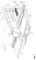
- a machine tool designed as a punching machine 1 has a C-shaped machine frame 2 with an upper frame leg 3, a lower frame leg 4 and a leg intermediate space 5 provided between the upper frame leg 3 and the lower frame leg 4.
- a processing station in the form of a punching station 6.
- a tool holder 7 of the punching station 6 as a machining tool in FIG. 1 not individually recognizable punching tool.
- the tool holder 7 comprises a provided on the upper frame leg 3 of the machine frame 2 upper tool holder and a lower tool holder on the lower frame leg 4 of the machine frame. 2
- For punching processing of a sheet 8 acts a substitute in the upper tool holder punch in the usual way with a punching die, which in the in FIG. 1 is replaced by the sheet 8 hidden lower tool holder.
- a numerically controlled lifting drive of the punch in the direction of a double arrow 10 can be raised and lowered and thereby movable relative to the punching die.
- the punching tool inserted into the tool holder 7 of the punching station 6 comprises in the usual way a scraper.
- the leg gap 5 between the upper frame leg 3 and the lower frame leg 4 takes a designed as a coordinate guide 11 of conventional design guide device.
- the coordinate guide 11 includes a guide member in the form of a support rail 12 as a movement unit, which is guided longitudinally movably on a base support 13 of the coordinate guide 11.
- a two-part workpiece table 15 with table halves 15/1, 15/2 is attached on the base support 13.
- the two table halves 15/1, 15/2 are separated by a gap, within which the lower tool holder is arranged.
- clamping claws 17 and also storage locations 18 of a tool storage 19 are provided on the mounting rail 12.
- the clamping claws 17 are used for releasably fixing a sheet 8 to the support rail 12.
- the storage locations 18 of the tool storage 19 take as cutting tools punching tools 20, as they can be used instead of the inserted into the tool holder 7 of the punching station 6 punching tool.
- a punching tool 20 on the way to one of the storage locations 18 is in FIG. 2 shown.
- a plurality of memory locations 18 is provided for punching tools 20.
- the tool storage 19 is thus designed as a so-called linear magazine.
- FIG. 1 only empty memory locations 18 shown. In fact, the memory locations 18 on the support rail 12 are almost completely filled with punching tools 20.
- the base support 13 of the coordinate guide 11 extends with its longitudinal direction in a first axial direction (x-axis) and is movably guided in a second axial direction (y-axis) on the lower frame leg 4.
- the x-axis and the y-axis span a horizontal plane of motion.
- FIG. 1 An in FIG. 1 indicated motor drive 21 is used to generate movements of the base support 13 of the coordinate guide 11 along the lower frame leg 4 of the machine frame 2 (y-direction) and movements of the support rail 12 along the base support 13 (x-direction).
- the motor drive 21 is controlled by a numerical control device 22.
- the tool storage 19 move with the memory locations 18, the clamping claws 17 and optionally held by the clamping claws 17 sheet 8 in the y direction.
- the clamping claws 17 and optionally the sheet 8 With the mounting rail 12 of the tool memory 19 with the memory locations 18, the clamping claws 17 and optionally the sheet 8 relative to the base support 13 along the x-axis movable.
- a double gripper 23 with tool handling devices in the form of two gripper units 23/1, 23/2 is mounted on the upper frame leg 3 of the machine frame 2.
- the gripper units 23/1, 23/2 are mounted on a support structure 24.
- the gripper units 23/1, 23/2 are movable on a longitudinal guide 25 for the support structure 24 in the y-direction and thus in the longitudinal direction of the upper frame leg 3.
- each of the gripper units 23/1, 23/2 relative to the support structure 24 in the x-direction and thus in the transverse direction of the upper frame leg 3 deliverable.
- a motor drive 26 To generate the movements of the gripper units 23/1, 23/2 of the double gripper 23 along the x-axis and along the y-axis is a motor drive 26 with a numerical control device 27.
- the numerical control device 27 of the motor drive 26 of the gripper units 23 / 1, 23/2 is just like the numerical control device 22 of the motor drive 21 of the support rail 12 in a numerical machine control 28 of the punching machine 1 integrated.
- a numerical machining program for operating the punching machine 1 is processed.
- the numerical machining program is generated by means of a programming system.
- An essential part of the programming system is a computer program product for generating the individual control commands of the numerical machining program.
- the gripper units 23/1, 23/2 of the double gripper 23 can access both the memory locations 18 of the tool memory 19 on the mounting rail 12 of the coordinate guide 11 and on a tool tray 29 which is attached to the rear end of the machine frame 2 and a plurality of memory locations 30 for punching tools 20.
- the tool tray 29 forms a processing station remote tool storage, the tool storage 19 on the support rail 12 is compared to the tool tray 29 arranged processing station close.
- FIG. 1 shows the machine tool 1 during the processing of the sheet 8 by means of the in the tool holder 7 of the punching station 6 substitute punch.
- the sheet 8 to be processed is fixed by means of the clamping claws 17 on the support rail 12 and is delivered to create the desired punched by corresponding movements of the support rail 12 relative to the punching tool of the punching station 6.
- the support rail 12 is thereby moved by means of the base support 13. Movements in the x-direction, the support rail 12 optionally along the base support 13 from.
- the section line to be created in the present example on the sheet 8 punch is in FIG. 1 indicated by dashed lines. Accordingly, the punching to be created extends in the y-direction from the inside of the sheet 8 to the in FIG. 1 front sheet edge.
- the gripper unit 23/1 of the double gripper 23 Along the upper frame leg 3 - and, if necessary - in the transverse direction of the upper frame leg 3 in a position in which the gripper unit 23/1 above that punching tool 20 on the tool tray 29 is that after completion of the current sheet metal processing operation to be transferred to a specific memory location 18 of the tool memory 19 on the support rail 12. Also during the ongoing sheet metal processing, the gripper unit 23/1 is lowered to the relevant punching tool 20 on the tool tray 29. After the gripper unit 23/1 has received the punching tool 20, the gripper unit 23/1 moves by means of the controlled motor drive 26 in the direction of the punching station 6 into a transfer / transfer position. Instead of the gripper unit 23/1 and the Greifereineit 23/2 of the double gripper 23 could be used.
- the transfer / transfer position of the gripper unit 23/1 is defined by the numerical control device 27 of the motor drive 26 of the gripper unit 23/1 as a function of a set-up position of the support rail 12.
- the setup position of the mounting rail 12 is predetermined by the numerical control device 22 of the motor drive 21 of the mounting rail 12 as a function of a machining position of the mounting rail 12.
- In this processing position of the support rail 12 is the position which the support rail 12 occupies at the time at which the punching station 6 mecanicchselte punching tool performs the final punching stroke of the current machining operation.
- the set-up position of the mounting rail 12 is defined by the mounting rail 12 starting from the processing position on the shortest path approachable position in which the storage space 18 on the support rail 12, for which the held on the gripper unit 23/1 punching tool 20 is determined for the gripper unit 23/1 is accessible.
- the conditions are such that the processing position of the support rail 12 at the time of the final punching stroke of the current machining operation directly represents the setup position of the support rail 12.
- the storage space 18 of the mounting rail 12 to be populated accordingly assumes a position already at the time of the final punching stroke of the current machining operation in which it is accessible to the previously moved into a corresponding transfer / takeover position gripper unit 23/1.
- the support rail 12 in the setup position and the gripper unit 23/1 in the transfer / transfer position are in FIG. 2 shown.
- the gripper unit 23/1 with the punching tool 20 located thereon is opposite the storage space 18 of the mounting rail 12 to be loaded in the vertical direction. Now only one lowering movement of the gripper unit 23/1 is required in order to transfer the punching tool 20 to the storage space 18 of the tool storage 19 provided thereon on the support rail 12.
- the transfer of the punching tool 20 from the gripper unit 23/1 to the respective storage location 18 of the support rail 12 can be carried out simultaneously with the final punching stroke of the current machining operation and thus parallel to the main time or immediately after the final punching stroke of the current machining operation.
- a conditional by the preparation of the relevant memory space 18 interruption of the process flow is thereby completely avoided, at least the period required for the preparation of the respective memory space 18 on the support rail 12 and can not be used as a secondary time for sheet metal processing, minimized.
- the transfer / transfer position of the gripper unit 23/1 depending on a tool change position be defined, which occupies the support rail 12 before starting a set-up position.
- the punching station 20 at the punching station 6 is first transferred to a storage space 18 of the tool storage 19 on the support rail 12. Subsequently, the support rail 12 is moved relative to the tool holder 7 such that the punching tool 20, which is to be used instead of the original punching tool 20 at the punching station 6, can be transferred to the tool holder 7.
- the mounting rail 12 assumes the tool changing position to which the set-up position of the mounting rail 12 and the transfer / transfer position of the gripper unit 23 / 1 or the gripper unit 23/2 of the double gripper 23 are tuned.
- the numerical control device 22 of the motor drive 21 of the support rail 12 defines as setup position of the support rail 12 that position of the support rail 12, in which a memory space to be equipped 18 of the support rail 12 for the gripper unit 23/1 or the gripper unit 23rd / 2 is accessible and can be approached by the support rail 12, starting from the tool change position on the shortest path.
- the numerical control device 27 of the motor drive 26 of the double gripper 23 determines the transfer / transfer position of the respective gripper unit 23/1, 23/2.
- the setup position of the support rail 12 and the transfer / takeover position of the gripper units 23/1, 23/2 of the double gripper 23 are defined in dependence on a processing position of the support rail 12, in which the support rail 12th is moved starting from the setup position.
- the machining position of the support rail 12 to be taken into consideration by the numerical control device 22 of the motor drive 21 is that position which the support rail 12 occupies at the time of the first punch stroke of the subsequent sheet metal working.
- the tool change position of the support rail 12 is in this case the position of the support rail 12, from which the tool change is carried out by appropriate movement of the support rail 12.
Landscapes
- Engineering & Computer Science (AREA)
- Mechanical Engineering (AREA)
- Mounting, Exchange, And Manufacturing Of Dies (AREA)
- Automatic Tool Replacement In Machine Tools (AREA)
- Turning (AREA)
- Punching Or Piercing (AREA)
Priority Applications (4)
| Application Number | Priority Date | Filing Date | Title |
|---|---|---|---|
| EP14166860.8A EP2939756B1 (fr) | 2014-05-02 | 2014-05-02 | Machine-outil de traitement d'une pièce à usiner avec un dispositif de changement d'outil et un magasin d'outils ainsi que procédé de mise en oeuvre et programme de fonctionnement d'une telle machine-outil |
| CN201510208260.2A CN105014454B (zh) | 2014-05-02 | 2015-04-28 | 用于加工工件的机床和操作这种机床的方法 |
| US14/701,990 US9855631B2 (en) | 2014-05-02 | 2015-05-01 | Machine tool for processing a workpiece and method for operating such a machine tool |
| JP2015094336A JP6625344B2 (ja) | 2014-05-02 | 2015-05-01 | ワークピースを加工する工作機械およびこのような工作機械を運転する方法 |
Applications Claiming Priority (1)
| Application Number | Priority Date | Filing Date | Title |
|---|---|---|---|
| EP14166860.8A EP2939756B1 (fr) | 2014-05-02 | 2014-05-02 | Machine-outil de traitement d'une pièce à usiner avec un dispositif de changement d'outil et un magasin d'outils ainsi que procédé de mise en oeuvre et programme de fonctionnement d'une telle machine-outil |
Publications (2)
| Publication Number | Publication Date |
|---|---|
| EP2939756A1 true EP2939756A1 (fr) | 2015-11-04 |
| EP2939756B1 EP2939756B1 (fr) | 2016-07-06 |
Family
ID=50639311
Family Applications (1)
| Application Number | Title | Priority Date | Filing Date |
|---|---|---|---|
| EP14166860.8A Active EP2939756B1 (fr) | 2014-05-02 | 2014-05-02 | Machine-outil de traitement d'une pièce à usiner avec un dispositif de changement d'outil et un magasin d'outils ainsi que procédé de mise en oeuvre et programme de fonctionnement d'une telle machine-outil |
Country Status (4)
| Country | Link |
|---|---|
| US (1) | US9855631B2 (fr) |
| EP (1) | EP2939756B1 (fr) |
| JP (1) | JP6625344B2 (fr) |
| CN (1) | CN105014454B (fr) |
Families Citing this family (3)
| Publication number | Priority date | Publication date | Assignee | Title |
|---|---|---|---|---|
| EP2692455B1 (fr) * | 2012-08-01 | 2015-06-24 | TRUMPF Werkzeugmaschinen GmbH + Co. KG | Machine-outil pour l'usinage de pièces en forme de plaque, notamment de tôles |
| DE102016118175B4 (de) * | 2016-09-26 | 2018-08-23 | Trumpf Werkzeugmaschinen Gmbh & Co. Kg | Werkzeugmaschine und Verfahren zum Bearbeiten von plattenförmigen Werkstücken |
| CN109143979B (zh) * | 2018-09-28 | 2020-12-25 | 浙江大学华南工业技术研究院 | 数控设备的加工控制方法、系统、可读存储介质和设备 |
Citations (5)
| Publication number | Priority date | Publication date | Assignee | Title |
|---|---|---|---|---|
| US5669866A (en) * | 1996-06-10 | 1997-09-23 | W. A. Whitney Co. | Punch press with tool changer |
| EP0927600A1 (fr) * | 1997-12-26 | 1999-07-07 | Murata Kikai Kabushiki Kaisha | Presse |
| EP2198991A1 (fr) | 2008-12-22 | 2010-06-23 | Trumpf Werkzeugmaschinen GmbH + Co. KG | Unité de chargement et de déchargement de tôles dotée d'une réception d'outil pour machines de traitement de tôle |
| EP2692455A1 (fr) * | 2012-08-01 | 2014-02-05 | TRUMPF Werkzeugmaschinen GmbH + Co. KG | Machine-outil pour l'usinage de pièces en forme de plaque, notamment de tôles |
| EP2724797A1 (fr) * | 2012-10-26 | 2014-04-30 | TRUMPF Werkzeugmaschinen GmbH + Co. KG | Magasin d'outils pour outils d'une machine-outil, agencement mécanique avec un tel magasin d'outils et procédé de gestion d'outils sur un agencement mécanique de ce type |
Family Cites Families (8)
| Publication number | Priority date | Publication date | Assignee | Title |
|---|---|---|---|---|
| US5224915A (en) * | 1992-09-09 | 1993-07-06 | Trumpf Inc. | Punch press with dual tool changing assemblies and method of punching |
| US6641511B2 (en) * | 2000-08-31 | 2003-11-04 | Hurco Companies, Inc. | Movable arm activated tool changer for machine tool system |
| US20020151420A1 (en) * | 2001-04-12 | 2002-10-17 | Scott William B. | Worktable Apparatus |
| JP4342928B2 (ja) * | 2003-12-25 | 2009-10-14 | 株式会社森精機製作所 | 工作機械の工具交換装置 |
| EP1839806B1 (fr) * | 2006-03-27 | 2009-04-29 | Fanuc Ltd | Procédé et dispositif de changement automatique d'outil pour une machine-outil commandée par un contrôleur numérique |
| BR112012020457A2 (pt) * | 2010-02-18 | 2017-06-13 | Gmtk Multi-Process Machining S A | equipamento para a troca em máquinas operatrizes com um êmbolo de componentes substituíveis de categorias diferentes, método para a troca de dois componentes substituíveis de duas categorias diferentes e programa de computador para a troca em máquinas operatrizes de componentes substituíveis de categorias diferentes |
| DE102010028678B4 (de) * | 2010-05-06 | 2012-01-19 | Trumpf Werkzeugmaschinen Gmbh + Co. Kg | Werkzeughalterung, Werkzeugmaschine mit einer derartigen Werkzeughalterung sowie Verfahren zum Festlegen eines Bearbeitungswerkzeuges an einer Werkzeughalterung einer Werkzeugmaschine |
| EP2444173B1 (fr) * | 2010-10-20 | 2013-11-27 | TRUMPF Sachsen GmbH | Agencement mécanique pour le traitement de tôles ainsi que procédé de changement d'outil pour un tel agencement mécanique |
-
2014
- 2014-05-02 EP EP14166860.8A patent/EP2939756B1/fr active Active
-
2015
- 2015-04-28 CN CN201510208260.2A patent/CN105014454B/zh active Active
- 2015-05-01 US US14/701,990 patent/US9855631B2/en active Active
- 2015-05-01 JP JP2015094336A patent/JP6625344B2/ja not_active Expired - Fee Related
Patent Citations (5)
| Publication number | Priority date | Publication date | Assignee | Title |
|---|---|---|---|---|
| US5669866A (en) * | 1996-06-10 | 1997-09-23 | W. A. Whitney Co. | Punch press with tool changer |
| EP0927600A1 (fr) * | 1997-12-26 | 1999-07-07 | Murata Kikai Kabushiki Kaisha | Presse |
| EP2198991A1 (fr) | 2008-12-22 | 2010-06-23 | Trumpf Werkzeugmaschinen GmbH + Co. KG | Unité de chargement et de déchargement de tôles dotée d'une réception d'outil pour machines de traitement de tôle |
| EP2692455A1 (fr) * | 2012-08-01 | 2014-02-05 | TRUMPF Werkzeugmaschinen GmbH + Co. KG | Machine-outil pour l'usinage de pièces en forme de plaque, notamment de tôles |
| EP2724797A1 (fr) * | 2012-10-26 | 2014-04-30 | TRUMPF Werkzeugmaschinen GmbH + Co. KG | Magasin d'outils pour outils d'une machine-outil, agencement mécanique avec un tel magasin d'outils et procédé de gestion d'outils sur un agencement mécanique de ce type |
Also Published As
| Publication number | Publication date |
|---|---|
| EP2939756B1 (fr) | 2016-07-06 |
| US9855631B2 (en) | 2018-01-02 |
| CN105014454B (zh) | 2019-02-01 |
| CN105014454A (zh) | 2015-11-04 |
| JP6625344B2 (ja) | 2019-12-25 |
| JP2015211986A (ja) | 2015-11-26 |
| US20150314408A1 (en) | 2015-11-05 |
Similar Documents
| Publication | Publication Date | Title |
|---|---|---|
| EP2656937B1 (fr) | Procédé pour ménager une déformation dans une plaque en tôle | |
| EP2198991B1 (fr) | Unité de chargement et de déchargement de tôles dotée d'une réception d'outil pour machines de traitement de tôle | |
| EP3515626B1 (fr) | Machine-outil et procédé d'usinage de pièces en forme de plaque | |
| EP3515624A1 (fr) | Procédé, machine-outil et outil de découpage pour le découpage continu à course multiple de pièces en forme de plaque | |
| EP3515623B1 (fr) | Outil et machine-outil ainsi que procédé d'usinage de pièces en forme de plaque, en particulier de tôles | |
| EP2939756B1 (fr) | Machine-outil de traitement d'une pièce à usiner avec un dispositif de changement d'outil et un magasin d'outils ainsi que procédé de mise en oeuvre et programme de fonctionnement d'une telle machine-outil | |
| EP2067544B1 (fr) | Procédé et machine-outil destinés au traitement de pièces à usiner | |
| WO2018055183A1 (fr) | Outil et machine-outil et procédé de traitement de pièces en forme de plaques | |
| EP2243569A1 (fr) | Procédé d'usinage ainsi qu'agencement mécanique de traitement de pièces usinées de types plaques, notamment de tôles | |
| EP2692455B1 (fr) | Machine-outil pour l'usinage de pièces en forme de plaque, notamment de tôles | |
| EP3515628B1 (fr) | Procédé et machine-outil servant à l'usinage de pièces en forme de plaque, en particulier de tôles | |
| EP2623244B1 (fr) | Procédé destiné au fonctionnement d'une machine-outil et machine-outil | |
| EP3880475B1 (fr) | Procédé d'apprentissage et / ou de fonctionnement d'un procédé de laminage et / ou d'un dispositif de laminage, procédé de laminage d'un élément de film, procédé d'installation et de conversion d'un dispositif de laminage pour laminer un élément de film, dispositif de laminage d'un élément de film, station d'enseignement et élément de film. | |
| AT507106A1 (de) | Verfahren zur ansteuerung des werkstückmanipulators einer werkzeugmaschine | |
| DE102019209923B4 (de) | Verfahren zum Transportieren von Werkstückteilen | |
| DE102013007670A1 (de) | Verzahnmaschine zur Verzahnbearbeitung von Werkstücken | |
| EP3292949B1 (fr) | Procédé de positionnement réciproque des unités de rangement d'un rangement de pièces à usiner, rangement de pièces à usiner, machine-outil pourvue de rangement de pièces à usiner et programme de commande | |
| DE102016120139B4 (de) | Verfahren, Werkzeugmaschine und Schlitzwerkzeug zum mehrhubig fortschreitenden Schlitzen von plattenförmigen Werkstücken | |
| WO2012059195A2 (fr) | Dispositif pour usiner une pièce de grand format | |
| DE102016120151A1 (de) | Verfahren und Werkzeugmaschine zum Bearbeiten von plattenförmigen Werkstücken, insbesondere von Blechen | |
| DE102016119464B4 (de) | Werkzeug und Werkzeugmaschine sowie Verfahren zur Bearbeitung von plattenförmigen Werkstücken | |
| DE102006051245A1 (de) | Fertigungseinrichtung | |
| EP4067079B1 (fr) | Procédé d'apprentissage et/ou de fonctionnement d'un dispositif de contrecollage | |
| AT521623B1 (de) | Verfahren zur Bereitstellung von zumindest zwei Biegewerkzeuggruppen | |
| EP3627258A1 (fr) | Planification de mouvement pour une presse servo |
Legal Events
| Date | Code | Title | Description |
|---|---|---|---|
| PUAI | Public reference made under article 153(3) epc to a published international application that has entered the european phase |
Free format text: ORIGINAL CODE: 0009012 |
|
| AK | Designated contracting states |
Kind code of ref document: A1 Designated state(s): AL AT BE BG CH CY CZ DE DK EE ES FI FR GB GR HR HU IE IS IT LI LT LU LV MC MK MT NL NO PL PT RO RS SE SI SK SM TR |
|
| AX | Request for extension of the european patent |
Extension state: BA ME |
|
| 17P | Request for examination filed |
Effective date: 20151020 |
|
| RBV | Designated contracting states (corrected) |
Designated state(s): AL AT BE BG CH CY CZ DE DK EE ES FI FR GB GR HR HU IE IS IT LI LT LU LV MC MK MT NL NO PL PT RO RS SE SI SK SM TR |
|
| GRAP | Despatch of communication of intention to grant a patent |
Free format text: ORIGINAL CODE: EPIDOSNIGR1 |
|
| RIC1 | Information provided on ipc code assigned before grant |
Ipc: G05B 19/4093 20060101ALI20151123BHEP Ipc: B21D 37/14 20060101AFI20151123BHEP Ipc: B23Q 3/155 20060101ALI20151123BHEP |
|
| INTG | Intention to grant announced |
Effective date: 20151215 |
|
| GRAS | Grant fee paid |
Free format text: ORIGINAL CODE: EPIDOSNIGR3 |
|
| GRAA | (expected) grant |
Free format text: ORIGINAL CODE: 0009210 |
|
| AK | Designated contracting states |
Kind code of ref document: B1 Designated state(s): AL AT BE BG CH CY CZ DE DK EE ES FI FR GB GR HR HU IE IS IT LI LT LU LV MC MK MT NL NO PL PT RO RS SE SI SK SM TR |
|
| REG | Reference to a national code |
Ref country code: GB Ref legal event code: FG4D Free format text: NOT ENGLISH |
|
| REG | Reference to a national code |
Ref country code: AT Ref legal event code: REF Ref document number: 810336 Country of ref document: AT Kind code of ref document: T Effective date: 20160715 Ref country code: CH Ref legal event code: EP |
|
| REG | Reference to a national code |
Ref country code: IE Ref legal event code: FG4D Free format text: LANGUAGE OF EP DOCUMENT: GERMAN |
|
| REG | Reference to a national code |
Ref country code: DE Ref legal event code: R096 Ref document number: 502014001040 Country of ref document: DE |
|
| REG | Reference to a national code |
Ref country code: NL Ref legal event code: MP Effective date: 20160706 |
|
| REG | Reference to a national code |
Ref country code: LT Ref legal event code: MG4D |
|
| PG25 | Lapsed in a contracting state [announced via postgrant information from national office to epo] |
Ref country code: HR Free format text: LAPSE BECAUSE OF FAILURE TO SUBMIT A TRANSLATION OF THE DESCRIPTION OR TO PAY THE FEE WITHIN THE PRESCRIBED TIME-LIMIT Effective date: 20160706 Ref country code: FI Free format text: LAPSE BECAUSE OF FAILURE TO SUBMIT A TRANSLATION OF THE DESCRIPTION OR TO PAY THE FEE WITHIN THE PRESCRIBED TIME-LIMIT Effective date: 20160706 Ref country code: NL Free format text: LAPSE BECAUSE OF FAILURE TO SUBMIT A TRANSLATION OF THE DESCRIPTION OR TO PAY THE FEE WITHIN THE PRESCRIBED TIME-LIMIT Effective date: 20160706 Ref country code: RS Free format text: LAPSE BECAUSE OF FAILURE TO SUBMIT A TRANSLATION OF THE DESCRIPTION OR TO PAY THE FEE WITHIN THE PRESCRIBED TIME-LIMIT Effective date: 20160706 Ref country code: NO Free format text: LAPSE BECAUSE OF FAILURE TO SUBMIT A TRANSLATION OF THE DESCRIPTION OR TO PAY THE FEE WITHIN THE PRESCRIBED TIME-LIMIT Effective date: 20161006 Ref country code: IS Free format text: LAPSE BECAUSE OF FAILURE TO SUBMIT A TRANSLATION OF THE DESCRIPTION OR TO PAY THE FEE WITHIN THE PRESCRIBED TIME-LIMIT Effective date: 20161106 Ref country code: LT Free format text: LAPSE BECAUSE OF FAILURE TO SUBMIT A TRANSLATION OF THE DESCRIPTION OR TO PAY THE FEE WITHIN THE PRESCRIBED TIME-LIMIT Effective date: 20160706 |
|
| PG25 | Lapsed in a contracting state [announced via postgrant information from national office to epo] |
Ref country code: GR Free format text: LAPSE BECAUSE OF FAILURE TO SUBMIT A TRANSLATION OF THE DESCRIPTION OR TO PAY THE FEE WITHIN THE PRESCRIBED TIME-LIMIT Effective date: 20161007 Ref country code: PT Free format text: LAPSE BECAUSE OF FAILURE TO SUBMIT A TRANSLATION OF THE DESCRIPTION OR TO PAY THE FEE WITHIN THE PRESCRIBED TIME-LIMIT Effective date: 20161107 Ref country code: SE Free format text: LAPSE BECAUSE OF FAILURE TO SUBMIT A TRANSLATION OF THE DESCRIPTION OR TO PAY THE FEE WITHIN THE PRESCRIBED TIME-LIMIT Effective date: 20160706 Ref country code: PL Free format text: LAPSE BECAUSE OF FAILURE TO SUBMIT A TRANSLATION OF THE DESCRIPTION OR TO PAY THE FEE WITHIN THE PRESCRIBED TIME-LIMIT Effective date: 20160706 Ref country code: ES Free format text: LAPSE BECAUSE OF FAILURE TO SUBMIT A TRANSLATION OF THE DESCRIPTION OR TO PAY THE FEE WITHIN THE PRESCRIBED TIME-LIMIT Effective date: 20160706 Ref country code: LV Free format text: LAPSE BECAUSE OF FAILURE TO SUBMIT A TRANSLATION OF THE DESCRIPTION OR TO PAY THE FEE WITHIN THE PRESCRIBED TIME-LIMIT Effective date: 20160706 |
|
| REG | Reference to a national code |
Ref country code: DE Ref legal event code: R097 Ref document number: 502014001040 Country of ref document: DE |
|
| PG25 | Lapsed in a contracting state [announced via postgrant information from national office to epo] |
Ref country code: EE Free format text: LAPSE BECAUSE OF FAILURE TO SUBMIT A TRANSLATION OF THE DESCRIPTION OR TO PAY THE FEE WITHIN THE PRESCRIBED TIME-LIMIT Effective date: 20160706 Ref country code: RO Free format text: LAPSE BECAUSE OF FAILURE TO SUBMIT A TRANSLATION OF THE DESCRIPTION OR TO PAY THE FEE WITHIN THE PRESCRIBED TIME-LIMIT Effective date: 20160706 |
|
| PLBE | No opposition filed within time limit |
Free format text: ORIGINAL CODE: 0009261 |
|
| STAA | Information on the status of an ep patent application or granted ep patent |
Free format text: STATUS: NO OPPOSITION FILED WITHIN TIME LIMIT |
|
| REG | Reference to a national code |
Ref country code: FR Ref legal event code: PLFP Year of fee payment: 4 |
|
| PG25 | Lapsed in a contracting state [announced via postgrant information from national office to epo] |
Ref country code: DK Free format text: LAPSE BECAUSE OF FAILURE TO SUBMIT A TRANSLATION OF THE DESCRIPTION OR TO PAY THE FEE WITHIN THE PRESCRIBED TIME-LIMIT Effective date: 20160706 Ref country code: SK Free format text: LAPSE BECAUSE OF FAILURE TO SUBMIT A TRANSLATION OF THE DESCRIPTION OR TO PAY THE FEE WITHIN THE PRESCRIBED TIME-LIMIT Effective date: 20160706 Ref country code: SM Free format text: LAPSE BECAUSE OF FAILURE TO SUBMIT A TRANSLATION OF THE DESCRIPTION OR TO PAY THE FEE WITHIN THE PRESCRIBED TIME-LIMIT Effective date: 20160706 Ref country code: BG Free format text: LAPSE BECAUSE OF FAILURE TO SUBMIT A TRANSLATION OF THE DESCRIPTION OR TO PAY THE FEE WITHIN THE PRESCRIBED TIME-LIMIT Effective date: 20161006 |
|
| 26N | No opposition filed |
Effective date: 20170407 |
|
| PG25 | Lapsed in a contracting state [announced via postgrant information from national office to epo] |
Ref country code: SI Free format text: LAPSE BECAUSE OF FAILURE TO SUBMIT A TRANSLATION OF THE DESCRIPTION OR TO PAY THE FEE WITHIN THE PRESCRIBED TIME-LIMIT Effective date: 20160706 Ref country code: LU Free format text: LAPSE BECAUSE OF NON-PAYMENT OF DUE FEES Effective date: 20170531 |
|
| REG | Reference to a national code |
Ref country code: CH Ref legal event code: PL |
|
| PG25 | Lapsed in a contracting state [announced via postgrant information from national office to epo] |
Ref country code: MC Free format text: LAPSE BECAUSE OF FAILURE TO SUBMIT A TRANSLATION OF THE DESCRIPTION OR TO PAY THE FEE WITHIN THE PRESCRIBED TIME-LIMIT Effective date: 20160706 |
|
| REG | Reference to a national code |
Ref country code: IE Ref legal event code: MM4A |
|
| PG25 | Lapsed in a contracting state [announced via postgrant information from national office to epo] |
Ref country code: CH Free format text: LAPSE BECAUSE OF NON-PAYMENT OF DUE FEES Effective date: 20170531 Ref country code: LI Free format text: LAPSE BECAUSE OF NON-PAYMENT OF DUE FEES Effective date: 20170531 |
|
| PG25 | Lapsed in a contracting state [announced via postgrant information from national office to epo] |
Ref country code: LU Free format text: LAPSE BECAUSE OF NON-PAYMENT OF DUE FEES Effective date: 20170502 |
|
| REG | Reference to a national code |
Ref country code: BE Ref legal event code: MM Effective date: 20170531 |
|
| PG25 | Lapsed in a contracting state [announced via postgrant information from national office to epo] |
Ref country code: IE Free format text: LAPSE BECAUSE OF NON-PAYMENT OF DUE FEES Effective date: 20170502 |
|
| REG | Reference to a national code |
Ref country code: FR Ref legal event code: PLFP Year of fee payment: 5 |
|
| PG25 | Lapsed in a contracting state [announced via postgrant information from national office to epo] |
Ref country code: BE Free format text: LAPSE BECAUSE OF NON-PAYMENT OF DUE FEES Effective date: 20170531 |
|
| PG25 | Lapsed in a contracting state [announced via postgrant information from national office to epo] |
Ref country code: MT Free format text: LAPSE BECAUSE OF FAILURE TO SUBMIT A TRANSLATION OF THE DESCRIPTION OR TO PAY THE FEE WITHIN THE PRESCRIBED TIME-LIMIT Effective date: 20160706 |
|
| PG25 | Lapsed in a contracting state [announced via postgrant information from national office to epo] |
Ref country code: AL Free format text: LAPSE BECAUSE OF FAILURE TO SUBMIT A TRANSLATION OF THE DESCRIPTION OR TO PAY THE FEE WITHIN THE PRESCRIBED TIME-LIMIT Effective date: 20160706 |
|
| GBPC | Gb: european patent ceased through non-payment of renewal fee |
Effective date: 20180502 |
|
| PG25 | Lapsed in a contracting state [announced via postgrant information from national office to epo] |
Ref country code: GB Free format text: LAPSE BECAUSE OF NON-PAYMENT OF DUE FEES Effective date: 20180502 |
|
| PG25 | Lapsed in a contracting state [announced via postgrant information from national office to epo] |
Ref country code: HU Free format text: LAPSE BECAUSE OF FAILURE TO SUBMIT A TRANSLATION OF THE DESCRIPTION OR TO PAY THE FEE WITHIN THE PRESCRIBED TIME-LIMIT; INVALID AB INITIO Effective date: 20140502 |
|
| PG25 | Lapsed in a contracting state [announced via postgrant information from national office to epo] |
Ref country code: CY Free format text: LAPSE BECAUSE OF FAILURE TO SUBMIT A TRANSLATION OF THE DESCRIPTION OR TO PAY THE FEE WITHIN THE PRESCRIBED TIME-LIMIT Effective date: 20160706 |
|
| PG25 | Lapsed in a contracting state [announced via postgrant information from national office to epo] |
Ref country code: MK Free format text: LAPSE BECAUSE OF FAILURE TO SUBMIT A TRANSLATION OF THE DESCRIPTION OR TO PAY THE FEE WITHIN THE PRESCRIBED TIME-LIMIT Effective date: 20160706 |
|
| PG25 | Lapsed in a contracting state [announced via postgrant information from national office to epo] |
Ref country code: TR Free format text: LAPSE BECAUSE OF FAILURE TO SUBMIT A TRANSLATION OF THE DESCRIPTION OR TO PAY THE FEE WITHIN THE PRESCRIBED TIME-LIMIT Effective date: 20160706 |
|
| REG | Reference to a national code |
Ref country code: AT Ref legal event code: MM01 Ref document number: 810336 Country of ref document: AT Kind code of ref document: T Effective date: 20190502 |
|
| PG25 | Lapsed in a contracting state [announced via postgrant information from national office to epo] |
Ref country code: AT Free format text: LAPSE BECAUSE OF NON-PAYMENT OF DUE FEES Effective date: 20190502 |
|
| PGFP | Annual fee paid to national office [announced via postgrant information from national office to epo] |
Ref country code: FR Payment date: 20210525 Year of fee payment: 8 |
|
| PGFP | Annual fee paid to national office [announced via postgrant information from national office to epo] |
Ref country code: IT Payment date: 20220524 Year of fee payment: 9 Ref country code: CZ Payment date: 20220429 Year of fee payment: 9 |
|
| PG25 | Lapsed in a contracting state [announced via postgrant information from national office to epo] |
Ref country code: FR Free format text: LAPSE BECAUSE OF NON-PAYMENT OF DUE FEES Effective date: 20220531 |
|
| PG25 | Lapsed in a contracting state [announced via postgrant information from national office to epo] |
Ref country code: CZ Free format text: LAPSE BECAUSE OF NON-PAYMENT OF DUE FEES Effective date: 20230502 |
|
| PG25 | Lapsed in a contracting state [announced via postgrant information from national office to epo] |
Ref country code: IT Free format text: LAPSE BECAUSE OF NON-PAYMENT OF DUE FEES Effective date: 20230502 |
|
| PGFP | Annual fee paid to national office [announced via postgrant information from national office to epo] |
Ref country code: DE Payment date: 20250521 Year of fee payment: 12 |