EP2939774A1 - Mèche et procédé pour fabriquer un produit coupé l'utilisant - Google Patents
Mèche et procédé pour fabriquer un produit coupé l'utilisant Download PDFInfo
- Publication number
- EP2939774A1 EP2939774A1 EP13869362.7A EP13869362A EP2939774A1 EP 2939774 A1 EP2939774 A1 EP 2939774A1 EP 13869362 A EP13869362 A EP 13869362A EP 2939774 A1 EP2939774 A1 EP 2939774A1
- Authority
- EP
- European Patent Office
- Prior art keywords
- drill
- central axis
- cutting
- cutting edge
- drill according
- Prior art date
- Legal status (The legal status is an assumption and is not a legal conclusion. Google has not performed a legal analysis and makes no representation as to the accuracy of the status listed.)
- Granted
Links
Images






Classifications
-
- B—PERFORMING OPERATIONS; TRANSPORTING
- B23—MACHINE TOOLS; METAL-WORKING NOT OTHERWISE PROVIDED FOR
- B23B—TURNING; BORING
- B23B51/00—Tools for drilling machines
-
- B—PERFORMING OPERATIONS; TRANSPORTING
- B23—MACHINE TOOLS; METAL-WORKING NOT OTHERWISE PROVIDED FOR
- B23B—TURNING; BORING
- B23B51/00—Tools for drilling machines
- B23B51/02—Twist drills
-
- B—PERFORMING OPERATIONS; TRANSPORTING
- B23—MACHINE TOOLS; METAL-WORKING NOT OTHERWISE PROVIDED FOR
- B23C—MILLING
- B23C5/00—Milling-cutters
- B23C5/16—Milling-cutters characterised by physical features other than shape
- B23C5/20—Milling-cutters characterised by physical features other than shape with removable cutter bits or teeth or cutting inserts
- B23C5/22—Securing arrangements for bits or teeth or cutting inserts
-
- B—PERFORMING OPERATIONS; TRANSPORTING
- B23—MACHINE TOOLS; METAL-WORKING NOT OTHERWISE PROVIDED FOR
- B23B—TURNING; BORING
- B23B2251/00—Details of tools for drilling machines
- B23B2251/02—Connections between shanks and removable cutting heads
-
- B—PERFORMING OPERATIONS; TRANSPORTING
- B23—MACHINE TOOLS; METAL-WORKING NOT OTHERWISE PROVIDED FOR
- B23B—TURNING; BORING
- B23B2251/00—Details of tools for drilling machines
- B23B2251/40—Flutes, i.e. chip conveying grooves
- B23B2251/408—Spiral grooves
-
- Y—GENERAL TAGGING OF NEW TECHNOLOGICAL DEVELOPMENTS; GENERAL TAGGING OF CROSS-SECTIONAL TECHNOLOGIES SPANNING OVER SEVERAL SECTIONS OF THE IPC; TECHNICAL SUBJECTS COVERED BY FORMER USPC CROSS-REFERENCE ART COLLECTIONS [XRACs] AND DIGESTS
- Y10—TECHNICAL SUBJECTS COVERED BY FORMER USPC
- Y10T—TECHNICAL SUBJECTS COVERED BY FORMER US CLASSIFICATION
- Y10T408/00—Cutting by use of rotating axially moving tool
- Y10T408/03—Processes
- Y10T408/04—Bit detachable
-
- Y—GENERAL TAGGING OF NEW TECHNOLOGICAL DEVELOPMENTS; GENERAL TAGGING OF CROSS-SECTIONAL TECHNOLOGIES SPANNING OVER SEVERAL SECTIONS OF THE IPC; TECHNICAL SUBJECTS COVERED BY FORMER USPC CROSS-REFERENCE ART COLLECTIONS [XRACs] AND DIGESTS
- Y10—TECHNICAL SUBJECTS COVERED BY FORMER USPC
- Y10T—TECHNICAL SUBJECTS COVERED BY FORMER US CLASSIFICATION
- Y10T408/00—Cutting by use of rotating axially moving tool
- Y10T408/89—Tool or Tool with support
- Y10T408/909—Having peripherally spaced cutting edges
- Y10T408/9095—Having peripherally spaced cutting edges with axially extending relief channel
- Y10T408/9097—Spiral channel
Definitions
- the present invention relates to a drill and a method of producing a machined product using the drill.
- Japanese Unexamined Patent Publication No. 2004-306170 discloses an indexable tool tip having a pair of torque receiving surfaces and a pair of clamp receiving surfaces.
- the torque receiving surfaces respectively intersect a rear end surface and a front end surface of a tip body and an outer peripheral surface of the tip body, and are oriented rearward in a rotation direction of a drill.
- the clamp receiving surfaces are respectively adjacent to the torque receiving surfaces. These clamp receiving surfaces and these torque receiving surfaces are respectively disposed in point symmetry with respect to an axis when viewed from the front end surface.
- each of these surfaces is disposed point-symmetrically with respect to the axis in the indexable tool tip.
- An object of the present invention is to provide the drill having both excellent drilling performance and easy attachment performance, and provide a method of producing a machined product using the drill.
- a drill according to an embodiment of the present invention has a cutting tip and a holder.
- the cutting tip has a first cutting edge and a second cutting edge located away from each other at a front end portion of the cutting tip, a first flute and a second flute which are respectively continuous with the first cutting edge and the second cutting edge on a front side in a rotation direction, and extend toward a rear end portion side of the cutting tip, a first side surface and a second side surface which are respectively continuous with the first flute and the second flute on the front side in the rotation direction, and extend toward the front side in the rotation direction, a first constraining surface and a second constraining surface which are respectively continuous with the first side surface and the second side surface on the front side in the rotation direction, and extend in a tilt direction with respect to the rotation direction, and a bottom surface located on the rear end portion.
- the holder is located on the rear end portion side of the cutting tip.
- the holder has a mounting surface being in contact with the bottom surface, a first contact surface and a second contact surface being respectively in contact with the first side surface and the second side surface, and a first hold surface and a second hold surface being respectively in contact with the first constraining surface and the second constraining surface.
- the first side surface and the second side surface are asymmetric with respect to a central axis, and the first constraining surface and the second constraining surface are point symmetric with respect to the central axis in a front end view.
- the drill 1 of the present embodiment generally has a holder 20 to be held by a rotative spindle or the like of a machine tool, and a cutting tip 10 attached to a front end portion 20a of the holder 20.
- the holder 20 is to be designed according to the shape of a rotary shaft of the machine tool (not shown).
- the cutting tip 10 is a major part to be brought into contact with a workpiece so as to perform cutting.
- the drill 1 of the present embodiment is a double-edged drill having two cutting edges 11A and 11B as shown in Fig. 2 .
- Arrow "a" indicated in Fig. 1 and the like is a rotation direction of the drill 1.
- the cutting tip 10 has a major role in cutting the workpiece.
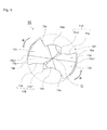
- the cutting tip 10 of the present embodiment is of indexable type that is attachable to and detachable from the holder 20 as described later. As shown in Fig. 5 , the cutting tip 10 has a first cutting edge 11a and a second cutting edge 11b, a first flute 12a and a second flute 12b, a first side surface 14a and a second side surface 14b, a first constraining surface 15a and a second constraining surface 15b, and a bottom surface 17.
- the first cutting edge 11a and the second cutting edge 11b are located away from each other at a front end portion as shown in Fig. 2 .
- the first flute 12a and the second flute 12b are respectively continuous with the first cutting edge 11a and the second cutting edge 11b on a front side in the rotation direction as shown in Fig. 5 .
- the first flute 12a and the second flute 12b extend toward a rear end portion side.
- the first side surface 14a and the second side surface 14b are respectively continuous with the first flute 12a and the second flute 12b on the front side in the rotation direction as shown in Fig. 2 .
- the first side surface 14a and the second side surface 14b extend toward the front side in the rotation direction.
- the first constraining surface 15a and the second constraining surface 15b are respectively continuous with the first side surface 14a and the second side surface 14b on the front side in the rotation direction.
- the first constraining surface 15a and the second constraining surface 15b extend in a tilt direction with respect to the rotation direction.
- the bottom surface 17 is located closer to a rear end portion 10b as shown in Fig. 6 . Components are described in sequence below.
- first cutting edge 11a and second cutting edge 11b are major portions for cutting the workpiece and are formed at a front end portion 10a of the cutting tip 10.
- first cutting edge 11a and the second cutting edge 11b are located to have 180 degree rotational symmetry with respect to a central axis O (axis) of the cutting tip 10 as shown in Fig. 5 .
- first cutting edge 11a and the second cutting edge 11b have dyad symmetry with respect to the central axis O.
- first cutting edge 11a and the second cutting edge 11b are point symmetric with respect to the central axis O when the cutting tip 10 is viewed from the front end portion 10a.
- the arrangement of the first cutting edge 11a and the second cutting edge 11b ensures improvement of straight advance stability during machining of the workpiece.
- the central axis O of the cutting tip 10 is the axis extending between the front end portion 10a and the rear end portion 10b, and denotes the axis serving as a rotation axis when the cutting tip 10 is rotated in a state in which the cutting tip 10 is viewed from the front end portion 10a.
- the central axis O of the cutting tip 10 lies at the same position as the rotation axis of the holder and the drill which is described later.
- the rotation axis of the holder and the drill described later is described as the rotation axis O by using the same reference character as the central axis O of the cutting tip 10.
- chisel edges (first chisel edge 11a1 and second chisel edge 11b1) are located closest to the front end portion 10a of the cutting tip 10 as shown in Fig. 4 .
- the chisel edges 11a1 and 11b1 have a role in cutting the workpiece together with the first cutting edge 11a and the second cutting edge 11b.
- thinning surfaces 11a2 and 11b2 are disposed so as to be continuous with a second flank surface 13b on a side opposite to that on a first flank surface 13a. These thinning surfaces 11a2 and 11b2 may be cut flat so as to be further tilted toward the rear end portion 10b as departing from the second flank surface 13b. This makes it possible to reduce cutting resistance applied to the chisel edges 11a1 and 11b1 during a cutting process.
- first flute 12a and second flute 12b have a primary purpose of discharging chips generated by two cutting edges 11A and 11B to the outside.
- first flute 12a and the second flute 12b are respectively continuous with the first cutting edge 11a and the second cutting edge 11b as shown in Fig. 5(b) .
- the first flute 12a and the second flute 12b extend spirally from the front end portion to the rear end portion of the cutting tip 10 (toward the holder 20).
- a flute width of the first flute 12a and a flute width of the second flute 12b are identical, and a depth of the first flute 12a and a depth of the second flute 12b are constant.
- chips generated by the first cutting edge 11a are basically discharged toward the rear end portion 10b (toward the holder 20) through the first flute 12a being continuous with the first cutting edge 11a
- chips generated by the second cutting edge 11b are basically discharged toward the rear end portion 10b (toward the holder 20) through the second flute 12b being continuous with the second cutting edge 11b.
- Chips generated by the first chisel edge 11a1 being continuous with the first cutting edge 11a and chips generated by the second chisel edge 11b1 being continuous with the second cutting edge 11b go through the second flank surface 13b of the two flank surfaces (first flank surface 13a and second flank surface 13b), which are located correspondingly to the chisel edges 11a1 and 11b1, to the first flute 12a and the second flute 12b, and the chips are then discharged toward the rear end portion 10b.
- These flank surfaces have a role in reducing cutting resistance by avoiding contact with the workpiece.
- first side surface 14a and second side surface 14b are to be brought into contact with contact surfaces of the holder described later upon attachment to the holder.
- first side surface 14a and the second side surface 14b respectively lie continuously with the first flute 12a and the second flute 12b on the front side in the rotation direction.
- the first side surface 14a and the second side surface 14b extend toward the front side in the rotation direction.
- the first side surface 14a and the second side surface 14b are asymmetric with respect to the central axis O in a front end view as shown in Fig. 5 .
- the first side surface 14a and the second side surface 14b in the cutting tip 10 which are subjected to relatively less influence of cutting force, are asymmetric with respect to the central axis O in the front end view. Therefore, when attaching the cutting chip 10 to the holder, a smooth attachment operation is ensured without making a mistake in attachment direction.
- the first side surface 14a and the second side surface 14b extend toward the front side in the rotation direction and hence are subjected to relatively less influence of cutting force, thereby making it possible to also have the effect of suppressing deterioration in cutting efficiency of the drill which can occur due to the asymmetric configuration.
- the first side surface 14a has an outwardly protruding circular arc shape in the front end view as shown in Fig. 5 .
- the circular arc of the first side surface 14a extends so as to form a concentric circle together with a circumscribed circle 10P of the cutting tip 10. This ensures that the first contact surface of the holder produces excellent strength against the cutting force in the rotation direction to be applied through the cutting tip 10 during the cutting process.
- the second side surface 14b has a straight line shape in the front end view as shown in Fig. 5 .
- the straight line shape that is simple and easy to manufacture, this shape is apparently different from the circular arc shape of the first side surface 14a. Therefore, when attaching the cutting chip 10 to the holder, a smooth attachment operation is ensured without making a mistake in attachment direction.
- the second side surface 14b having the straight line shape is located closer to the central axis O than the first side surface 14a having the circular arc shape in the front end view as shown in Fig. 5 .
- the first side surface 14a having the circular arc shape imparts excellent strength to the holder against the cutting force in the rotation direction, whereas the second side surface 14b has the straight line shape and hence the holder may be affected in terms of the cutting force in the rotation direction.
- the second side surface 14b having the straight line shape is located near the central axis O so as to be closer to the central axis O than the first side surface 14a, it is possible to reduce the influence of the second side surface 14b on the holder in terms of the cutting force in the rotation direction.
- opposite ends of the first side surface 14a and opposite ends of the second side surface 14b may be point symmetric with respect to the central axis O in the front end view. This ensures the improvement of straight advance stability during machining of the workpiece.
- the first side surface 14a and the second side surface 14b are preferably parallel to the central axis O.
- parallelism is to be determined by contrast with a cutting line obtained by cutting the side surface 14a in a direction along the central axis O.
- the two constraining surfaces are respectively in contact with hold surfaces 25a and 25b of the holder to be described later, and have a major role in cooperating with the hold surfaces 25a and 25b to receive the cutting force in the rotation direction generated during the cutting process.
- the first constraining surface 15a and the second constraining surface 15b respectively lie continuously with the first side surface 14a and the second side surface 14b on the front side in the rotation direction.
- the first constraining surface 15a and the second constraining surface 15b extend in a tilt direction with respect to the rotation direction.
- the tilt direction with respect to the rotation direction denotes not being a direction along the rotation direction. Specifically, this denotes that an angle formed by the first constraining surface 15a, the second constraining surface 15b, and the rotation direction has a non-zero degree in the front end view.
- the first constraining surface 15a and the second constraining surface 15b extend in a direction orthogonal to the rotation direction in the front end view. Therefore, an angle formed by the first constraining surface 15a, the second constraining surface 15b, and the rotation direction is 90 degrees. The case of being thus orthogonal is also included in the concept of the tilt direction with respect to the rotation direction.
- the first constraining surface 15a and the second constraining surface 15b extend in the direction orthogonal to the rotation direction as shown in Fig. 5 , and are point symmetric with respect to the central axis O in the front end view. This ensures that the cutting force in the rotation direction generated during the cutting process is received with excellent strength.
- first constraining surface 15a and the second constraining surface 15b may extend on the same straight line passing through the central axis O in the front end view. This ensures that the cutting force in the rotation direction generated during the cutting process is received from a more effective direction, thereby producing more excellent effect.
- first constraining surface 15a and the second constraining surface 15b also extend from the circumscribed circle 10P of the drill 10 toward the central axis O in the front end view.
- the first constraining surface 15a and the second constraining surface 15b preferably extend in a straight line shape.
- the first constraining surface 15a and the second constraining surface 15b are preferably flat surfaces.
- the first side surface 14a and the second side surface 14b need not directly be continuous with the first constraining surface 15a and the second constraining surface 15b, respectively.
- curved surface shaped connection surfaces may be respectively interposed therebetween.
- the first land 16a and the second land 16b are located above the circumscribed circle 10P of the cutting tip 10 and have a circular arc shape as shown in Fig. 5 .
- the circumscribed circle 10P of the cutting tip 10 is indicated by a dotted line in Fig. 5 .
- the cutting tip 10 may have clearances 16a1 and 16b1.
- the clearances 16a1 and 16b1 may be formed so as to extend from the front end portion 10a to a region close to the rear end portion 10b. This makes it possible to reduce contact between the drill and an inner wall of a drilled hole in the workpiece. This also contributes to improving chip discharge performance.
- the cutting tip 10 has the bottom surface 17 close to the rear end portion 10b as shown in Fig. 6 .
- the bottom surface 17 has a planar shape and is perpendicular to the central axis. This ensures that the bottom surface 17 cooperates with the mounting surface of the holder described later to receive a force exerted rearward in the direction of the central axis during the cutting.
- the first side surface 14a has the outwardly protruding circular arc shape in the front end view, a large area of the bottom surface 17 can be ensured without excessively increasing a distance from the central axis O of the first side surface 14a. This makes it possible to avoid an excessively small thickness from the first contact surface to the outer periphery in the holder, thereby stably receiving the force exerted rearward of the central axis O during the cutting.
- the cutting tip 10 also has a shaft foot 18 projecting from a central region of the bottom surface 17 as shown in Fig. 6 . This ensures improvement in easiness of attachment to the holder.
- the shaft foot 18 has a circular columnar shape whose axis is the central axis O as shown in Fig. 6 .
- the shaft foot 18 has a notched portion 18a to be brought into contact with a fixing member described later.
- the notched portion 18a of the shaft foot 18 is located on a straight line extending from the central axis O to the first contact surface 24a of the holder 20.
- the notched portion 18a and the first contact surface 24a are thus disposed to allow the cutting tip 10 to have excellent weight balance with respect to the central axis O, thereby improving the straight advance stability during machining of the workpiece.
- the second side surface 14b is located closer to the central axis O than the first side surface 14a. Accordingly, a center of gravity in the front end view is located deviatedly from the central axis O toward the first side surface 14a.
- the center of gravity in the front end perspective view is to be deviated toward the second side surface 14b by an amount being notched by the notched portion 18a of the shaft foot 18.
- the deviation of the center of gravity can be counterbalanced to minimize the deviation in the center of gravity of the cutting tip 1 from the central axis O in the front end perspective view. This contributes to improving the straight advance stability during machining of the workpiece.
- the first side surface 14a and the second side surface 14b which are asymmetric with respect to the central axis O in the front end view as shown in Fig. 5 , the first side surface 14a has the outwardly protruding circular arc shape and the second side surface 14b has the straight line shape.
- the specific shapes of the first side surface 14a and the second side surface 14b are not limited thereto.
- Modifications 1 to 4 are described below. Although these modifications differ from the foregoing embodiment in the shape of at least one of the first side surface 14a and the second side surface 14b, components other than these two side surfaces are identical to those of the foregoing embodiment. Therefore, descriptions of the components other than the first side surface 14a and the second side surface 14b are omitted here.
- the first side surface 14a and the second side surface 14b may be made to be asymmetric with respect to the central axis O by such a configuration that the first side surface 14a is located closer to the central axis O than the second side surface 14b.
- the first side surface 14a has a straight line shape and the second side surface 14b has an outwardly protruding circular arc shape in a front end view.
- the first side surface 14a may have an outwardly protruding circular arc shape
- the second side surface 14b may have a curved line shape not being circular arc.
- the second side surface 14b is located closer to the central axis O than the first side surface 14a.
- the first side surface 14a may have an outwardly protruding circular arc shape
- the second side surface 14b may be made up of a plurality of straight line shaped portions so as to have a generally concave shape.
- the first side surface 14a may have an outwardly protruding circular arc shape.
- most part of the second side surface 14b may have a circular arc shape, and the second side surface 14b may be partially provided with a concave shaped portion.
- first side surface 14a and the second side surface 14b are asymmetric with respect to the central axis O in the front end view, thereby producing an operation advantage similar to that of the foregoing embodiment.
- the holder 20 is configured to attach the cutting tip 10 to the front end portion 20a thereof so as to cooperate with the cutting tip 10 to perform cutting of a workpiece.
- the holder 20 of the present embodiment is located close to the rear end portion 10b of the cutting tip 10.
- the holder 20 has a mounting surface 27, a first contact surface 24a, a second contact surface 24b, and a first hold surface 25a and a second hold surface 25b.
- the mounting surface 27 is to be brought into contact with the bottom surface 17 of the cutting tip 10 shown in Fig. 5 .
- the first contact surface 24a and the second contact surface 24b are to be respectively brought into contact with the first side surface 14a and the second side surface 14b of the cutting tip 10 shown in Fig. 5 .
- the first hold surface 25a and the second hold surface 25b are to be respectively brought into contact with the first constraining surface 15a and the second constraining surface 15b of the cutting tip 10 shown in Fig. 5 .
- the holder 20 has a first major groove 22a and a second major groove 22b being respectively continuous with the first flue and the second flute of the cutting tip.
- the first major groove 22a and the second major groove 22b have a spiral shape.
- the mounting surface 27 shown in Fig. 11 is to be brought into contact with the bottom surface 17 of the cutting tip 10 shown in Fig. 5 when mounting the cutting tip.
- the mounting surface 27 is located at the front end portion 20a of the holder 20.
- the mounting surface 27 has an approximately identical shape to the bottom surface 17 of the cutting tip 10.
- a shaft receiving hole 28 is disposed on a middle region of the mounting surface 27.
- the shaft receiving hole 28 has a circular columnar shape whose axis is the central axis O in the present embodiment.
- the bottom surface 17 of the cutting tip 10 shown in Fig. 5 and the mounting surface 27 of the holder 20 shown in Fig. 12 are brought into contact with each other upon insertion of the shaft foot 18 of the cutting tip 10 into the shaft receiving hole 28. This ensures excellent strength against the force generated and applied in the direction of the central axis O during the cutting process.
- first contact surface 24a and second contact surface 24b shown in Figs. 2 and 12 are to be respectively brought into contact with the first side surface 14a and the second contact surface 14b of the cutting tip 10 shown in Figs. 4 to 10 when mounting the cutting tip 10.
- first contact surface 24a and the second contact surface 24b are asymmetric with respect to the central axis O in the front end view.
- the hold surfaces are to be respectively brought into contact with the first constraining surface 15a and the second constraining surface 15b when mounting the cutting tip 10 shown in Figs. 4 to 10 .
- first hold surface 25a and the second hold surface 25b extend from an outer periphery 20P of the holder 20 toward the central axis O in the front end view as shown in Fig. 12 .
- the first hold surface 25a and the second hold surface 25b preferably extend in a straight line shape.
- At least one of the first hold surface 25a and the second hold surface 25b is a flat surface.
- the holder 20 further has a through hole 29.
- the through hole 29 penetrates between the outer periphery P2 and the shaft receiving hole 28.
- the through hole 29 permits insertion therein of the later-described fixing member with the shaft foot 18 of the cutting tip 10 inserted into the shaft receiving hole 28 of the holder 20.
- the cutting tip 10 and the holder 20 thus configured are to be fixed to each other by bringing the fixing member inserted from the through hole 29 into contact with or press against the notched portion 18a of the shaft foot 18, with the shaft foot 18 of the cutting tip 10 inserted into the shaft receiving hole 28 of the holder 20.
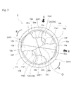
- a screw may be used as the fixing member 30 as shown in Figs. 1 and 3 .
- the drill 1 of the present embodiment is suitably usable as a drill with the cutting edges 11A and 11B having an outer diameter of 6 mm to 30 mm, preferably 8 mm to 25 mm.
- the drill 1 of the present embodiment is also suitably applicable to, for example, drilling of L/D of 5 or more in which L is an axial length (from the cutting edges 11A and 11B to terminals of the flutes 12a and 12b, respectively), and D is a diameter (an outer diameter of the cutting edges 11A and 11B).
- FIG. 14 An embodiment of a method of producing a machined product according to an embodiment of the present invention is described below with reference to Fig. 14 .
- the present embodiment is described taking as an example the drill 1 according to the foregoing embodiment.
- the method of producing a machined product according to the present embodiment has the following steps (i) to (iv):
- the machined product shown in Fig. 14(c) is produced through the foregoing individual steps.
- the drill 1 is capable of producing excellent drilling performance.
- the step (ii) may be carried out for example by fixing the workpiece 100 onto a table of a machine tool having the drill 1 attached thereto, and then bringing the drill 1 being rotated near the workpiece 100.
- the workpiece 100 and the drill 1 may be brought near each other.
- the workpiece 100 may be brought near the drill 1.
- a setting is preferably made so that a partial region of the cutting tip of the drill 1 which is close to the rear end portion thereof does not penetrate the workpiece 100. That is, excellent chip discharge performance is producible by allowing the partial region to function as a margin region for discharging chips.
- the workpiece 100 and the drill 1 may be separated from each other.
- the workpiece 100 may be separated from the drill 1.
- the foregoing embodiment has been described taking the double-edged drill as an example, the foregoing configurations may be applied to a triple-edged drill.
- the first side surface and the second side surface are asymmetric with respect to the central axis in the front end view.
- any one of a first side surface, a second side surface, and a third side surface may not be rotational symmetric with respect to the central axis in the front end view.
- the first side surface and the second side surface of the cutting tip which are subjected to relatively less influence of cutting force, are asymmetric with respect to the central axis in the front end view. Therefore, when attaching the cutting chip to the holder, a smooth attachment operation is ensured without making a mistake in attachment direction.
- the first side surface and the second side surface of the cutting tip are subjected to relatively less influence of cutting force and are therefore capable of also having the effect of suppressing deterioration in cutting efficiency due to the drill.
- the shape of the cutting tip may be those normally employed by those skilled in the art without being limited to the configurations in the foregoing embodiments.
- the cutting tip may have such a tapered shape that a core thickness, namely a diameter of an inscribed circle in a cross section perpendicular to the central axis increases from the front end portion toward the rear end portion.
- the cutting tip may be tilted so that a drill diameter (outer diameter) increases or decreases from the front end portion toward the rear end portion.
- the cutting tip may have an undercut portion.
Landscapes
- Engineering & Computer Science (AREA)
- Mechanical Engineering (AREA)
- Drilling Tools (AREA)
Applications Claiming Priority (2)
| Application Number | Priority Date | Filing Date | Title |
|---|---|---|---|
| JP2012286990 | 2012-12-28 | ||
| PCT/JP2013/084384 WO2014103972A1 (fr) | 2012-12-28 | 2013-12-21 | Mèche et procédé pour fabriquer un produit coupé l'utilisant |
Publications (3)
| Publication Number | Publication Date |
|---|---|
| EP2939774A1 true EP2939774A1 (fr) | 2015-11-04 |
| EP2939774A4 EP2939774A4 (fr) | 2016-09-28 |
| EP2939774B1 EP2939774B1 (fr) | 2022-05-04 |
Family
ID=51021055
Family Applications (1)
| Application Number | Title | Priority Date | Filing Date |
|---|---|---|---|
| EP13869362.7A Active EP2939774B1 (fr) | 2012-12-28 | 2013-12-21 | Foret et procédé pour fabriquer un produit usiné l'utilisant |
Country Status (5)
| Country | Link |
|---|---|
| US (1) | US9555484B2 (fr) |
| EP (1) | EP2939774B1 (fr) |
| JP (1) | JP5909565B2 (fr) |
| CN (1) | CN104884202B (fr) |
| WO (1) | WO2014103972A1 (fr) |
Cited By (1)
| Publication number | Priority date | Publication date | Assignee | Title |
|---|---|---|---|---|
| EP3424630A4 (fr) * | 2016-03-04 | 2019-10-30 | Sumitomo Electric Hardmetal Corp. | Outil de coupe |
Families Citing this family (20)
| Publication number | Priority date | Publication date | Assignee | Title |
|---|---|---|---|---|
| KR101509954B1 (ko) * | 2013-10-29 | 2015-04-07 | 한국야금 주식회사 | 절삭 인서트 및 인덱서블 드릴 |
| CN104759664A (zh) * | 2015-04-21 | 2015-07-08 | 成都锋宜精密工具制造有限公司 | 自锁式可换头硬质合金钻头 |
| US11235397B2 (en) | 2016-12-16 | 2022-02-01 | Kennametal Inc. | Side-activated modular drill |
| CN108788265B (zh) * | 2017-05-05 | 2020-08-18 | 张新添 | 舍弃式倒角刀具 |
| US11872641B2 (en) * | 2017-05-29 | 2024-01-16 | Kyocera Corporation | Drill and method for manufacturing machined product |
| JP7023295B2 (ja) * | 2018-01-12 | 2022-02-21 | 京セラ株式会社 | ドリル及び切削加工物の製造方法 |
| DE102019116160A1 (de) | 2018-06-20 | 2019-12-24 | Kennametal Inc. | Seitlich geschlossener modularer Bohrer mit federunterstütztem Auswurf |
| EP3636370A4 (fr) * | 2018-08-07 | 2020-09-09 | Sumitomo Electric Hardmetal Corp. | Foret |
| US11090736B2 (en) | 2018-12-10 | 2021-08-17 | Kennametal Inc. | Side-activated modular drill |
| JP7516771B2 (ja) * | 2019-03-18 | 2024-07-17 | 三菱マテリアル株式会社 | 刃先交換式ドリル |
| CN112399898A (zh) * | 2019-06-13 | 2021-02-23 | 住友电工硬质合金株式会社 | 切削工具 |
| US11471952B2 (en) | 2020-03-19 | 2022-10-18 | Kennametal Inc. | Cutting tool having replaceable cutting head and method of securing a replaceable cutting head |
| CN112157298A (zh) * | 2020-10-20 | 2021-01-01 | 苏州阿诺精密切削技术有限公司 | 一种圆销定心单限位侧压锁紧齿冠刀头 |
| CN112157299A (zh) * | 2020-10-20 | 2021-01-01 | 苏州阿诺精密切削技术有限公司 | 一种圆销定心双限位侧压锁紧齿冠钻头 |
| CN112157296A (zh) * | 2020-10-20 | 2021-01-01 | 苏州阿诺精密切削技术有限公司 | 一种圆销定心双限位侧压锁紧齿冠刀头 |
| US11883888B2 (en) | 2021-06-28 | 2024-01-30 | Kennametal Inc. | Modular drill with enhanced bump-off capability |
| US12337398B2 (en) | 2021-10-21 | 2025-06-24 | Kennametal Inc. | Modular drill, method of assembly thereof, and cutting insert |
| JP1743974S (ja) * | 2022-11-04 | 2023-05-12 | 切削工具用ホルダ | |
| JP1743975S (ja) * | 2022-11-04 | 2023-05-12 | 切削工具用ホルダ | |
| JP1743973S (ja) * | 2022-11-04 | 2023-05-12 | 切削工具用ホルダ |
Family Cites Families (9)
| Publication number | Priority date | Publication date | Assignee | Title |
|---|---|---|---|---|
| JP4494582B2 (ja) * | 2000-03-31 | 2010-06-30 | 京セラ株式会社 | スローアウェイチップ及びスローアウェイチップ用ホルダ |
| DE10220023A1 (de) * | 2002-05-04 | 2003-11-20 | Tts Tooltechnic Systems Ag | Bohrer |
| JP4378989B2 (ja) | 2003-04-03 | 2009-12-09 | 三菱マテリアル株式会社 | スローアウェイ式ドリル及びこれに装着されるスローアウェイチップ |
| IL164888A (en) * | 2004-10-28 | 2009-07-20 | Iscar Ltd | Cutting tool and cutting head for it |
| SE532280C2 (sv) | 2008-04-14 | 2009-12-01 | Seco Tools Ab | Verktyg, verktygskropp och skärhuvud |
| DE102009012725B4 (de) | 2009-03-11 | 2020-10-15 | Kennametal Inc. | Bohrerspitze sowie Bohrwerkzeug mit einer Bohrerspitze |
| SE533855C2 (sv) * | 2009-06-23 | 2011-02-08 | Sandvik Intellectual Property | Roterbart verktyg för spånavskiljande bearbetning samt löstopp och grundkropp härför |
| SE533852C2 (sv) | 2009-06-23 | 2011-02-08 | Sandvik Intellectual Property | Roterbart verktyg för spånavskiljande bearbetning samt löstopp härför |
| DE112009002001B4 (de) * | 2009-12-08 | 2019-09-19 | Osg Corporation | Einweg-Rotationswerkzeug |
-
2013
- 2013-12-21 US US14/655,794 patent/US9555484B2/en active Active
- 2013-12-21 CN CN201380067796.6A patent/CN104884202B/zh active Active
- 2013-12-21 EP EP13869362.7A patent/EP2939774B1/fr active Active
- 2013-12-21 WO PCT/JP2013/084384 patent/WO2014103972A1/fr not_active Ceased
- 2013-12-21 JP JP2014554430A patent/JP5909565B2/ja active Active
Cited By (2)
| Publication number | Priority date | Publication date | Assignee | Title |
|---|---|---|---|---|
| EP3424630A4 (fr) * | 2016-03-04 | 2019-10-30 | Sumitomo Electric Hardmetal Corp. | Outil de coupe |
| US10766077B2 (en) | 2016-03-04 | 2020-09-08 | Sumitomo Electric Hardmetal Corp. | Cutting tool |
Also Published As
| Publication number | Publication date |
|---|---|
| JP5909565B2 (ja) | 2016-04-26 |
| WO2014103972A1 (fr) | 2014-07-03 |
| US20150328693A1 (en) | 2015-11-19 |
| EP2939774A4 (fr) | 2016-09-28 |
| EP2939774B1 (fr) | 2022-05-04 |
| JPWO2014103972A1 (ja) | 2017-01-12 |
| US9555484B2 (en) | 2017-01-31 |
| CN104884202B (zh) | 2017-04-12 |
| CN104884202A (zh) | 2015-09-02 |
Similar Documents
| Publication | Publication Date | Title |
|---|---|---|
| EP2939774B1 (fr) | Foret et procédé pour fabriquer un produit usiné l'utilisant | |
| JP6165165B2 (ja) | 割出し可能切削インサート、そのための切削工具およびクランプ方法 | |
| US10086444B2 (en) | Drill tip and drilling tool having a drill tip | |
| JPWO2012002267A1 (ja) | インサートおよび切削工具、並びにそれらを用いた切削加工物の製造方法 | |
| CN102198534A (zh) | 用于去屑加工的可旋转刀具及其可拆卸顶部和基体 | |
| JP5749400B2 (ja) | ドリル工具 | |
| CN1325214C (zh) | 用于刀具的防错设备 | |
| JP2009255202A (ja) | 深穴切削用ドリルヘッド | |
| CN102825274A (zh) | 开槽镶片 | |
| JP2019063977A (ja) | リーマ | |
| JP2019115939A (ja) | 回転工具及び切削加工物の製造方法 | |
| JP2013208692A (ja) | ドリル及びそれを用いた切削加工物の製造方法 | |
| EP2902142B1 (fr) | Mèche et procédé pour fabriquer des pièces à travailler de coupe l'utilisant | |
| CN105750596A (zh) | 钻头 | |
| US9085033B2 (en) | Drilling tool | |
| JP5845288B2 (ja) | ドリルおよびそれを用いた切削加工物の製造方法 | |
| KR102556228B1 (ko) | 다중 에지 리머 | |
| JP2007136563A (ja) | インサート式ドリル | |
| JP5319928B2 (ja) | ボーリング工具及び孔開け加工方法 | |
| JP2017042870A (ja) | リーマ | |
| JP2003266240A (ja) | 穴加工工具 | |
| JP2005022012A (ja) | ドリル | |
| JP2008161999A (ja) | 切削工具 | |
| JP6819187B2 (ja) | ボールエンドミル | |
| JP5589401B2 (ja) | 刃先交換式溝入れ工具及び端面溝入れ加工方法 |
Legal Events
| Date | Code | Title | Description |
|---|---|---|---|
| PUAI | Public reference made under article 153(3) epc to a published international application that has entered the european phase |
Free format text: ORIGINAL CODE: 0009012 |
|
| 17P | Request for examination filed |
Effective date: 20150624 |
|
| AK | Designated contracting states |
Kind code of ref document: A1 Designated state(s): AL AT BE BG CH CY CZ DE DK EE ES FI FR GB GR HR HU IE IS IT LI LT LU LV MC MK MT NL NO PL PT RO RS SE SI SK SM TR |
|
| AX | Request for extension of the european patent |
Extension state: BA ME |
|
| DAX | Request for extension of the european patent (deleted) | ||
| REG | Reference to a national code |
Ref country code: DE Ref legal event code: R079 Ref document number: 602013081590 Country of ref document: DE Free format text: PREVIOUS MAIN CLASS: B23B0051000000 Ipc: B23B0051020000 |
|
| A4 | Supplementary search report drawn up and despatched |
Effective date: 20160829 |
|
| RIC1 | Information provided on ipc code assigned before grant |
Ipc: B23B 51/02 20060101AFI20160823BHEP |
|
| GRAP | Despatch of communication of intention to grant a patent |
Free format text: ORIGINAL CODE: EPIDOSNIGR1 |
|
| STAA | Information on the status of an ep patent application or granted ep patent |
Free format text: STATUS: GRANT OF PATENT IS INTENDED |
|
| INTG | Intention to grant announced |
Effective date: 20211216 |
|
| GRAS | Grant fee paid |
Free format text: ORIGINAL CODE: EPIDOSNIGR3 |
|
| GRAA | (expected) grant |
Free format text: ORIGINAL CODE: 0009210 |
|
| STAA | Information on the status of an ep patent application or granted ep patent |
Free format text: STATUS: THE PATENT HAS BEEN GRANTED |
|
| AK | Designated contracting states |
Kind code of ref document: B1 Designated state(s): AL AT BE BG CH CY CZ DE DK EE ES FI FR GB GR HR HU IE IS IT LI LT LU LV MC MK MT NL NO PL PT RO RS SE SI SK SM TR |
|
| REG | Reference to a national code |
Ref country code: GB Ref legal event code: FG4D |
|
| REG | Reference to a national code |
Ref country code: CH Ref legal event code: EP |
|
| REG | Reference to a national code |
Ref country code: AT Ref legal event code: REF Ref document number: 1488484 Country of ref document: AT Kind code of ref document: T Effective date: 20220515 |
|
| REG | Reference to a national code |
Ref country code: IE Ref legal event code: FG4D Ref country code: DE Ref legal event code: R096 Ref document number: 602013081590 Country of ref document: DE |
|
| REG | Reference to a national code |
Ref country code: LT Ref legal event code: MG9D |
|
| REG | Reference to a national code |
Ref country code: NL Ref legal event code: MP Effective date: 20220504 |
|
| REG | Reference to a national code |
Ref country code: AT Ref legal event code: MK05 Ref document number: 1488484 Country of ref document: AT Kind code of ref document: T Effective date: 20220504 |
|
| PG25 | Lapsed in a contracting state [announced via postgrant information from national office to epo] |
Ref country code: SE Free format text: LAPSE BECAUSE OF FAILURE TO SUBMIT A TRANSLATION OF THE DESCRIPTION OR TO PAY THE FEE WITHIN THE PRESCRIBED TIME-LIMIT Effective date: 20220504 Ref country code: PT Free format text: LAPSE BECAUSE OF FAILURE TO SUBMIT A TRANSLATION OF THE DESCRIPTION OR TO PAY THE FEE WITHIN THE PRESCRIBED TIME-LIMIT Effective date: 20220905 Ref country code: NO Free format text: LAPSE BECAUSE OF FAILURE TO SUBMIT A TRANSLATION OF THE DESCRIPTION OR TO PAY THE FEE WITHIN THE PRESCRIBED TIME-LIMIT Effective date: 20220804 Ref country code: NL Free format text: LAPSE BECAUSE OF FAILURE TO SUBMIT A TRANSLATION OF THE DESCRIPTION OR TO PAY THE FEE WITHIN THE PRESCRIBED TIME-LIMIT Effective date: 20220504 Ref country code: LT Free format text: LAPSE BECAUSE OF FAILURE TO SUBMIT A TRANSLATION OF THE DESCRIPTION OR TO PAY THE FEE WITHIN THE PRESCRIBED TIME-LIMIT Effective date: 20220504 Ref country code: HR Free format text: LAPSE BECAUSE OF FAILURE TO SUBMIT A TRANSLATION OF THE DESCRIPTION OR TO PAY THE FEE WITHIN THE PRESCRIBED TIME-LIMIT Effective date: 20220504 Ref country code: GR Free format text: LAPSE BECAUSE OF FAILURE TO SUBMIT A TRANSLATION OF THE DESCRIPTION OR TO PAY THE FEE WITHIN THE PRESCRIBED TIME-LIMIT Effective date: 20220805 Ref country code: FI Free format text: LAPSE BECAUSE OF FAILURE TO SUBMIT A TRANSLATION OF THE DESCRIPTION OR TO PAY THE FEE WITHIN THE PRESCRIBED TIME-LIMIT Effective date: 20220504 Ref country code: ES Free format text: LAPSE BECAUSE OF FAILURE TO SUBMIT A TRANSLATION OF THE DESCRIPTION OR TO PAY THE FEE WITHIN THE PRESCRIBED TIME-LIMIT Effective date: 20220504 Ref country code: BG Free format text: LAPSE BECAUSE OF FAILURE TO SUBMIT A TRANSLATION OF THE DESCRIPTION OR TO PAY THE FEE WITHIN THE PRESCRIBED TIME-LIMIT Effective date: 20220804 Ref country code: AT Free format text: LAPSE BECAUSE OF FAILURE TO SUBMIT A TRANSLATION OF THE DESCRIPTION OR TO PAY THE FEE WITHIN THE PRESCRIBED TIME-LIMIT Effective date: 20220504 |
|
| PG25 | Lapsed in a contracting state [announced via postgrant information from national office to epo] |
Ref country code: RS Free format text: LAPSE BECAUSE OF FAILURE TO SUBMIT A TRANSLATION OF THE DESCRIPTION OR TO PAY THE FEE WITHIN THE PRESCRIBED TIME-LIMIT Effective date: 20220504 Ref country code: PL Free format text: LAPSE BECAUSE OF FAILURE TO SUBMIT A TRANSLATION OF THE DESCRIPTION OR TO PAY THE FEE WITHIN THE PRESCRIBED TIME-LIMIT Effective date: 20220504 Ref country code: LV Free format text: LAPSE BECAUSE OF FAILURE TO SUBMIT A TRANSLATION OF THE DESCRIPTION OR TO PAY THE FEE WITHIN THE PRESCRIBED TIME-LIMIT Effective date: 20220504 Ref country code: IS Free format text: LAPSE BECAUSE OF FAILURE TO SUBMIT A TRANSLATION OF THE DESCRIPTION OR TO PAY THE FEE WITHIN THE PRESCRIBED TIME-LIMIT Effective date: 20220904 |
|
| PG25 | Lapsed in a contracting state [announced via postgrant information from national office to epo] |
Ref country code: SM Free format text: LAPSE BECAUSE OF FAILURE TO SUBMIT A TRANSLATION OF THE DESCRIPTION OR TO PAY THE FEE WITHIN THE PRESCRIBED TIME-LIMIT Effective date: 20220504 Ref country code: SK Free format text: LAPSE BECAUSE OF FAILURE TO SUBMIT A TRANSLATION OF THE DESCRIPTION OR TO PAY THE FEE WITHIN THE PRESCRIBED TIME-LIMIT Effective date: 20220504 Ref country code: RO Free format text: LAPSE BECAUSE OF FAILURE TO SUBMIT A TRANSLATION OF THE DESCRIPTION OR TO PAY THE FEE WITHIN THE PRESCRIBED TIME-LIMIT Effective date: 20220504 Ref country code: EE Free format text: LAPSE BECAUSE OF FAILURE TO SUBMIT A TRANSLATION OF THE DESCRIPTION OR TO PAY THE FEE WITHIN THE PRESCRIBED TIME-LIMIT Effective date: 20220504 Ref country code: DK Free format text: LAPSE BECAUSE OF FAILURE TO SUBMIT A TRANSLATION OF THE DESCRIPTION OR TO PAY THE FEE WITHIN THE PRESCRIBED TIME-LIMIT Effective date: 20220504 Ref country code: CZ Free format text: LAPSE BECAUSE OF FAILURE TO SUBMIT A TRANSLATION OF THE DESCRIPTION OR TO PAY THE FEE WITHIN THE PRESCRIBED TIME-LIMIT Effective date: 20220504 |
|
| REG | Reference to a national code |
Ref country code: DE Ref legal event code: R097 Ref document number: 602013081590 Country of ref document: DE |
|
| PLBE | No opposition filed within time limit |
Free format text: ORIGINAL CODE: 0009261 |
|
| STAA | Information on the status of an ep patent application or granted ep patent |
Free format text: STATUS: NO OPPOSITION FILED WITHIN TIME LIMIT |
|
| PG25 | Lapsed in a contracting state [announced via postgrant information from national office to epo] |
Ref country code: AL Free format text: LAPSE BECAUSE OF FAILURE TO SUBMIT A TRANSLATION OF THE DESCRIPTION OR TO PAY THE FEE WITHIN THE PRESCRIBED TIME-LIMIT Effective date: 20220504 |
|
| 26N | No opposition filed |
Effective date: 20230207 |
|
| PG25 | Lapsed in a contracting state [announced via postgrant information from national office to epo] |
Ref country code: SI Free format text: LAPSE BECAUSE OF FAILURE TO SUBMIT A TRANSLATION OF THE DESCRIPTION OR TO PAY THE FEE WITHIN THE PRESCRIBED TIME-LIMIT Effective date: 20220504 |
|
| P01 | Opt-out of the competence of the unified patent court (upc) registered |
Effective date: 20230508 |
|
| REG | Reference to a national code |
Ref country code: CH Ref legal event code: PL |
|
| GBPC | Gb: european patent ceased through non-payment of renewal fee |
Effective date: 20221221 |
|
| REG | Reference to a national code |
Ref country code: BE Ref legal event code: MM Effective date: 20221231 |
|
| PG25 | Lapsed in a contracting state [announced via postgrant information from national office to epo] |
Ref country code: LU Free format text: LAPSE BECAUSE OF NON-PAYMENT OF DUE FEES Effective date: 20221221 |
|
| PG25 | Lapsed in a contracting state [announced via postgrant information from national office to epo] |
Ref country code: LI Free format text: LAPSE BECAUSE OF NON-PAYMENT OF DUE FEES Effective date: 20221231 Ref country code: IE Free format text: LAPSE BECAUSE OF NON-PAYMENT OF DUE FEES Effective date: 20221221 Ref country code: GB Free format text: LAPSE BECAUSE OF NON-PAYMENT OF DUE FEES Effective date: 20221221 Ref country code: CH Free format text: LAPSE BECAUSE OF NON-PAYMENT OF DUE FEES Effective date: 20221231 |
|
| PG25 | Lapsed in a contracting state [announced via postgrant information from national office to epo] |
Ref country code: FR Free format text: LAPSE BECAUSE OF NON-PAYMENT OF DUE FEES Effective date: 20221231 Ref country code: BE Free format text: LAPSE BECAUSE OF NON-PAYMENT OF DUE FEES Effective date: 20221231 |
|
| PG25 | Lapsed in a contracting state [announced via postgrant information from national office to epo] |
Ref country code: IT Free format text: LAPSE BECAUSE OF FAILURE TO SUBMIT A TRANSLATION OF THE DESCRIPTION OR TO PAY THE FEE WITHIN THE PRESCRIBED TIME-LIMIT Effective date: 20220504 |
|
| PG25 | Lapsed in a contracting state [announced via postgrant information from national office to epo] |
Ref country code: HU Free format text: LAPSE BECAUSE OF FAILURE TO SUBMIT A TRANSLATION OF THE DESCRIPTION OR TO PAY THE FEE WITHIN THE PRESCRIBED TIME-LIMIT; INVALID AB INITIO Effective date: 20131221 |
|
| PG25 | Lapsed in a contracting state [announced via postgrant information from national office to epo] |
Ref country code: CY Free format text: LAPSE BECAUSE OF FAILURE TO SUBMIT A TRANSLATION OF THE DESCRIPTION OR TO PAY THE FEE WITHIN THE PRESCRIBED TIME-LIMIT Effective date: 20220504 |
|
| PG25 | Lapsed in a contracting state [announced via postgrant information from national office to epo] |
Ref country code: MK Free format text: LAPSE BECAUSE OF FAILURE TO SUBMIT A TRANSLATION OF THE DESCRIPTION OR TO PAY THE FEE WITHIN THE PRESCRIBED TIME-LIMIT Effective date: 20220504 |
|
| PG25 | Lapsed in a contracting state [announced via postgrant information from national office to epo] |
Ref country code: MC Free format text: LAPSE BECAUSE OF FAILURE TO SUBMIT A TRANSLATION OF THE DESCRIPTION OR TO PAY THE FEE WITHIN THE PRESCRIBED TIME-LIMIT Effective date: 20220504 |
|
| PG25 | Lapsed in a contracting state [announced via postgrant information from national office to epo] |
Ref country code: MC Free format text: LAPSE BECAUSE OF FAILURE TO SUBMIT A TRANSLATION OF THE DESCRIPTION OR TO PAY THE FEE WITHIN THE PRESCRIBED TIME-LIMIT Effective date: 20220504 |
|
| PG25 | Lapsed in a contracting state [announced via postgrant information from national office to epo] |
Ref country code: MT Free format text: LAPSE BECAUSE OF FAILURE TO SUBMIT A TRANSLATION OF THE DESCRIPTION OR TO PAY THE FEE WITHIN THE PRESCRIBED TIME-LIMIT Effective date: 20220504 |
|
| PG25 | Lapsed in a contracting state [announced via postgrant information from national office to epo] |
Ref country code: BG Free format text: LAPSE BECAUSE OF FAILURE TO SUBMIT A TRANSLATION OF THE DESCRIPTION OR TO PAY THE FEE WITHIN THE PRESCRIBED TIME-LIMIT Effective date: 20220504 |
|
| PG25 | Lapsed in a contracting state [announced via postgrant information from national office to epo] |
Ref country code: BG Free format text: LAPSE BECAUSE OF FAILURE TO SUBMIT A TRANSLATION OF THE DESCRIPTION OR TO PAY THE FEE WITHIN THE PRESCRIBED TIME-LIMIT Effective date: 20220504 |
|
| PGFP | Annual fee paid to national office [announced via postgrant information from national office to epo] |
Ref country code: DE Payment date: 20241029 Year of fee payment: 12 |
|
| PG25 | Lapsed in a contracting state [announced via postgrant information from national office to epo] |
Ref country code: TR Free format text: LAPSE BECAUSE OF FAILURE TO SUBMIT A TRANSLATION OF THE DESCRIPTION OR TO PAY THE FEE WITHIN THE PRESCRIBED TIME-LIMIT Effective date: 20220504 |