EP2939837B1 - Conteneur de déchets liquides, fixation, unité de collecte de déchets liquides et appareil d'éjection de liquide - Google Patents
Conteneur de déchets liquides, fixation, unité de collecte de déchets liquides et appareil d'éjection de liquide Download PDFInfo
- Publication number
- EP2939837B1 EP2939837B1 EP15165658.4A EP15165658A EP2939837B1 EP 2939837 B1 EP2939837 B1 EP 2939837B1 EP 15165658 A EP15165658 A EP 15165658A EP 2939837 B1 EP2939837 B1 EP 2939837B1
- Authority
- EP
- European Patent Office
- Prior art keywords
- waste liquid
- mounting
- unit
- connection
- attachment
- Prior art date
- Legal status (The legal status is an assumption and is not a legal conclusion. Google has not performed a legal analysis and makes no representation as to the accuracy of the status listed.)
- Active
Links
Images









Classifications
-
- B—PERFORMING OPERATIONS; TRANSPORTING
- B41—PRINTING; LINING MACHINES; TYPEWRITERS; STAMPS
- B41J—TYPEWRITERS; SELECTIVE PRINTING MECHANISMS, i.e. MECHANISMS PRINTING OTHERWISE THAN FROM A FORME; CORRECTION OF TYPOGRAPHICAL ERRORS
- B41J2/00—Typewriters or selective printing mechanisms characterised by the printing or marking process for which they are designed
- B41J2/005—Typewriters or selective printing mechanisms characterised by the printing or marking process for which they are designed characterised by bringing liquid or particles selectively into contact with a printing material
- B41J2/01—Ink jet
- B41J2/135—Nozzles
- B41J2/165—Prevention or detection of nozzle clogging, e.g. cleaning, capping or moistening for nozzles
- B41J2/16517—Cleaning of print head nozzles
-
- B—PERFORMING OPERATIONS; TRANSPORTING
- B41—PRINTING; LINING MACHINES; TYPEWRITERS; STAMPS
- B41J—TYPEWRITERS; SELECTIVE PRINTING MECHANISMS, i.e. MECHANISMS PRINTING OTHERWISE THAN FROM A FORME; CORRECTION OF TYPOGRAPHICAL ERRORS
- B41J2/00—Typewriters or selective printing mechanisms characterised by the printing or marking process for which they are designed
- B41J2/005—Typewriters or selective printing mechanisms characterised by the printing or marking process for which they are designed characterised by bringing liquid or particles selectively into contact with a printing material
- B41J2/01—Ink jet
- B41J2/17—Ink jet characterised by ink handling
- B41J2/18—Ink recirculation systems
- B41J2/185—Ink-collectors; Ink-catchers
-
- B—PERFORMING OPERATIONS; TRANSPORTING
- B41—PRINTING; LINING MACHINES; TYPEWRITERS; STAMPS
- B41J—TYPEWRITERS; SELECTIVE PRINTING MECHANISMS, i.e. MECHANISMS PRINTING OTHERWISE THAN FROM A FORME; CORRECTION OF TYPOGRAPHICAL ERRORS
- B41J2/00—Typewriters or selective printing mechanisms characterised by the printing or marking process for which they are designed
- B41J2/005—Typewriters or selective printing mechanisms characterised by the printing or marking process for which they are designed characterised by bringing liquid or particles selectively into contact with a printing material
- B41J2/01—Ink jet
- B41J2/135—Nozzles
- B41J2/165—Prevention or detection of nozzle clogging, e.g. cleaning, capping or moistening for nozzles
- B41J2/16505—Caps, spittoons or covers for cleaning or preventing drying out
- B41J2/16508—Caps, spittoons or covers for cleaning or preventing drying out connected with the printer frame
-
- B—PERFORMING OPERATIONS; TRANSPORTING
- B41—PRINTING; LINING MACHINES; TYPEWRITERS; STAMPS
- B41J—TYPEWRITERS; SELECTIVE PRINTING MECHANISMS, i.e. MECHANISMS PRINTING OTHERWISE THAN FROM A FORME; CORRECTION OF TYPOGRAPHICAL ERRORS
- B41J2/00—Typewriters or selective printing mechanisms characterised by the printing or marking process for which they are designed
- B41J2/005—Typewriters or selective printing mechanisms characterised by the printing or marking process for which they are designed characterised by bringing liquid or particles selectively into contact with a printing material
- B41J2/01—Ink jet
- B41J2/135—Nozzles
- B41J2/165—Prevention or detection of nozzle clogging, e.g. cleaning, capping or moistening for nozzles
- B41J2/16517—Cleaning of print head nozzles
- B41J2/1652—Cleaning of print head nozzles by driving a fluid through the nozzles to the outside thereof, e.g. by applying pressure to the inside or vacuum at the outside of the print head
- B41J2/16523—Waste ink transport from caps or spittoons, e.g. by suction
-
- B—PERFORMING OPERATIONS; TRANSPORTING
- B41—PRINTING; LINING MACHINES; TYPEWRITERS; STAMPS
- B41J—TYPEWRITERS; SELECTIVE PRINTING MECHANISMS, i.e. MECHANISMS PRINTING OTHERWISE THAN FROM A FORME; CORRECTION OF TYPOGRAPHICAL ERRORS
- B41J2/00—Typewriters or selective printing mechanisms characterised by the printing or marking process for which they are designed
- B41J2/005—Typewriters or selective printing mechanisms characterised by the printing or marking process for which they are designed characterised by bringing liquid or particles selectively into contact with a printing material
- B41J2/01—Ink jet
- B41J2/135—Nozzles
- B41J2/165—Prevention or detection of nozzle clogging, e.g. cleaning, capping or moistening for nozzles
- B41J2/16517—Cleaning of print head nozzles
- B41J2/16535—Cleaning of print head nozzles using wiping constructions
- B41J2/16544—Constructions for the positioning of wipers
- B41J2/16547—Constructions for the positioning of wipers the wipers and caps or spittoons being on the same movable support
-
- B—PERFORMING OPERATIONS; TRANSPORTING
- B41—PRINTING; LINING MACHINES; TYPEWRITERS; STAMPS
- B41J—TYPEWRITERS; SELECTIVE PRINTING MECHANISMS, i.e. MECHANISMS PRINTING OTHERWISE THAN FROM A FORME; CORRECTION OF TYPOGRAPHICAL ERRORS
- B41J2/00—Typewriters or selective printing mechanisms characterised by the printing or marking process for which they are designed
- B41J2/005—Typewriters or selective printing mechanisms characterised by the printing or marking process for which they are designed characterised by bringing liquid or particles selectively into contact with a printing material
- B41J2/01—Ink jet
- B41J2/17—Ink jet characterised by ink handling
- B41J2/1721—Collecting waste ink; Collectors therefor
-
- B—PERFORMING OPERATIONS; TRANSPORTING
- B41—PRINTING; LINING MACHINES; TYPEWRITERS; STAMPS
- B41J—TYPEWRITERS; SELECTIVE PRINTING MECHANISMS, i.e. MECHANISMS PRINTING OTHERWISE THAN FROM A FORME; CORRECTION OF TYPOGRAPHICAL ERRORS
- B41J2/00—Typewriters or selective printing mechanisms characterised by the printing or marking process for which they are designed
- B41J2/005—Typewriters or selective printing mechanisms characterised by the printing or marking process for which they are designed characterised by bringing liquid or particles selectively into contact with a printing material
- B41J2/01—Ink jet
- B41J2/17—Ink jet characterised by ink handling
- B41J2/18—Ink recirculation systems
- B41J2/185—Ink-collectors; Ink-catchers
- B41J2002/1856—Ink-collectors; Ink-catchers waste ink containers
Definitions
- the present invention relates to a liquid ejecting apparatus such as an ink jet printer and a waste liquid container, an attachment, and a waste liquid collection unit applied to the liquid ejecting apparatus.
- a liquid ejecting apparatus there is an ink jet printer that performs printing by ejecting ink from nozzles formed in a liquid ejecting head.
- the ink is discharged as a waste liquid from the nozzles and the discharged waste liquid is contained in a waste liquid container detachably mounted on a mounting mechanism in some cases.
- a waste liquid container includes a container member that can contain the waste liquid, a circuit substrate that stores various kinds of information regarding a capacity or the like of the waste liquid, a connection terminal of the circuit substrate, and a guide portion that positions an apparatus-side connection terminal at the time of the mounting on the mounting mechanism (for example, see JP-A-2013-216010 ).
- JP 2009 269203 discloses a waste liquid collector which can be detachably mounted on a device discharging a waste liquid, and is capable of ensuring a connection state where a connection terminal appropriately comes in contact with a device-side connection terminal when the waste liquid collector is mounted on the device.
- a waste ink tank 27 which is detachably mounted on a printer including a discharge portion discharging a waste ink and stores the waste ink discharged from the discharge portion when the waste ink tank is mounted on the printer includes: a connection port 57 through which the discharge portion is inserted or extracted when mounting or detaching the waste ink tank on or from the printer; and a connection terminal 59 which comes in contact with a connection terminal 87 included in the printer when the discharge portion is inserted into the connection port, wherein the connection terminal 59 is provided so that its contact surface 59a to the printer-side connection terminal 87 may be non-perpendicular to a straight line L extending toward a radial direction from a center 57a of the connection port.
- the waste liquid container includes a waste liquid introduction portion which is opened upward.
- the waste liquid flowing down from the vertically upper side of the waste liquid container is introduced into the container member via the waste liquid introduction portion.
- the waste liquid introduction portion opened toward a lateral side it is possible to obtain the advantage that the height of the waste liquid container can be reduced, compared to the case in which the waste liquid is introduce from the waste liquid introduction portion opened upward.
- This problem is not limited to only the waste liquid container detachably mounted on the printer, but is nearly common to waste liquid containers detachably mounted on mounting units.
- An advantage of some aspects of the invention is that it provides a waste liquid container which can be mounted on a mounting unit while the positions of a waste liquid discharge portion formed in the mounting unit and a substrate connection portion are aligned and a liquid ejecting apparatus on which the waste liquid container is mounted.
- a waste liquid container detachably mounted on a mounting unit which includes a discharge portion discharging a waste liquid and a projection to which a substrate connection portion is joined.
- the waste liquid container includes: a containing portion that is able to contain the waste liquid; a connection concave portion that is opened in a mounting direction in regard to the mounting unit so that the projection is insertable at a time of mounting on the mounting unit; a circuit substrate that includes connection terminals electrically connected to the substrate connection portion at the time of the mounting on the mounting unit and is joined to the connection concave portion; and a waste liquid introduction portion that is connected to the discharge portion at the time of the mounting on the mounting unit.
- connection concave portion one pair of guide portions guiding the projection at the time of the mounting on the mounting unit is formed so that the connection terminals are interposed therebetween in a width direction intersecting the mounting direction.
- one guide portion is disposed between the connection terminals and the waste liquid introduction portion in the width direction.
- the projection is inserted into the connection concave portion of the waste liquid container so that the positions of the connection terminals recessed in the connection concave portion can be substantially aligned with the position of the substrate connection portion recessed in the projection. Subsequently, the projection is guided by the pair of guide portions in the connection concave portion, so that the positions of the connection terminals are accurately aligned with the substrate connection portion.
- One of the pair of guide portions is disposed between the connection terminals and the waste liquid introduction portion in the width direction. Therefore, when the positions of the connection terminals are aligned, the position of the waste liquid introduction portion can be aligned. Accordingly, the waste liquid container can be mounted on the mounting unit while the position of the waste liquid container is aligned with the substrate connection portion and the discharge portion of the waste liquid formed in the mounting unit.
- the one guide portion may protrude in a wall portion forming the waste liquid introduction portion and the connection concave portion to project toward an inside of the connection concave portion.
- the distance between the waste liquid introduction portion and the guide portion is shortened.
- the position of the waste liquid introduction portion can be aligned accurately by the guide portions.
- the one pair of guide portions may include a guide surface extending in the mounting direction and the width direction.
- the waste liquid introduction portion may be opened in the mounting direction and an opening center of the waste liquid introduction portion may be located on a plane including the guide surface.
- the opening center of the waste liquid introduction portion is located on the plane including the guide surface of the one pair of guide portions. Therefore, the guide surface guides the projection formed in the mounting unit, and thus the position of the waste liquid introduction portion can be aligned in the direction intersecting both of the mounting direction and the width direction.
- connection terminals may be disposed to face a region between the one guide portion and the other guide portion of the one pair of guide portions.
- connection terminals are disposed to face the region between the one guide portion and the other guide portion of the one pair of guide portions. Therefore, the positions of the connection terminals can be accurately aligned with the substrate connection portion more than when the region and the connection terminals are distant from each other in the mounting direction.
- the substrate connection portion may include a movable contact portion elastically deformable according to a contact pressure.
- the one pair of guide portions may engage with the projection by an elastic restoration force of the movable contact portion which is pressed against the connection terminals and is elastically deformed.
- the guide portions and the projection engage with each other by the elastic restoration force of the movable contact portion pressed by the connection terminals, so that the state in which the movable contact portion comes into contact with the connection terminals by the predetermined contact pressure can be maintained.
- the state in which the connection terminals are electrically connected to the substrate connection portion can be maintained.
- connection concave portion and the waste liquid introduction portion may be formed to be arranged in the width direction in a convex portion protruding from the containing portion in the mounting direction. Both ends of the convex portion in the width direction may be disposed in the width direction more inside than both ends of the containing portion in the width direction.
- both ends of the convex portion in the width direction are disposed inside both ends of the containing portion in the width direction, it is possible to suppress unnecessary collision of the connection concave portion and the waste liquid introduction portion to other members or the like more than when the connection concave portion and the waste liquid introduction portion are disposed at the end in the width direction.
- the waste liquid container may further include an absorber that is able to absorb the waste liquid; an accommodation member in which an accommodation concave portion capable of accommodating the absorber is formed; a film member that covers an opening of the accommodation concave portion; and a reinforcement member that is disposed between the absorber and the film member.
- the containing portion may be surrounded by the accommodation concave portion and the film member.
- the size of the accommodation concave portion can be reduced in the depth direction more easily than when the opening of the accommodation concave portion is covered with a plate-shaped member.
- the accommodation member may include a protrusion projecting inside the accommodation concave portion.
- the absorber may include an insertion portion into which the protrusion is insertable.
- the reinforcement member may be disposed between the protrusion and the film member.
- the reinforcement member may be formed of a sheet-shaped resin material.
- the reinforcement member in the sheet shape, it is possible to ensure a large space for accommodating the absorber inside the accommodation concave portion. Further, a resin material is easily molded, and thus is suitable to form the reinforcement member in the sheet shape.
- a liquid ejecting apparatus including: a liquid ejecting unit that is able to eject a liquid; and a mounting unit on which the foregoing waste liquid container is detachably mounted.
- the mounting unit includes a discharge portion discharging a waste liquid and a projection to which a substrate connection portion is joined.
- an attachment which is a separate body from a waste liquid containing unit accommodated in an accommodation chamber, in which a mounting unit including a discharge portion discharging a waste liquid to a waste liquid containing unit and a projection in which a substrate connection portion is formed is formed, in a state in which the liquid containing unit is mounted on the mounting unit.
- the attachment includes: a connection concave portion that is opened in a mounting direction in regard to the mounting unit so that the projection is insertable at a time of mounting on the mounting unit; and a circuit substrate that includes connection terminals electrically connected to the substrate connection portion at the time of the mounting on the mounting unit and is joined to the connection concave portion.
- the connection concave portion one pair of guide portions guiding the projection at the time of the mounting on the mounting unit is formed so that the connection terminals are interposed therebetween in a width direction intersecting the mounting direction.
- the projection is inserted into the connection concave portion of the attachment so that the positions of the connection terminals recessed in the connection concave portion can be substantially aligned with the position of the substrate connection portion provided to the projection. Subsequently, the projection is guided by the pair of guide portions in the connection concave portion, so that the positions of the connection terminals are accurately aligned with the substrate connection portion. Accordingly, the attachment can be mounted on the mounting unit while the position of the attachment is aligned with the substrate connection portion formed in the mounting unit.
- the volume of the waste liquid containing unit can be increased without an influence on the volume (size) of the accommodation chamber in which the attachment is accommodated. Accordingly, by increasing the size of the waste liquid containing unit and increasing the amount of waste liquid which can be contained in the waste liquid containing unit, it is possible to discharge the more waste liquid from the discharge portion.
- the attachment may further include a waste liquid introduction portion that is connected to the discharge portion at the time of the mounting on the mounting unit.
- a waste liquid introduction portion that is connected to the discharge portion at the time of the mounting on the mounting unit.
- one guide portion is disposed between the connection terminals and the waste liquid introduction portion in the width direction.
- the discharge portion of the mounting unit is connected to the waste liquid introduction portion of the attachment. Therefore, the waste liquid can be discharged from the discharge portion to the waste liquid containing unit via the attachment.
- one of the pair of guide portions is disposed between the connection terminals and the waste liquid introduction portion in the width direction. Therefore, when the positions of the connection terminals are aligned, the position of the waste liquid introduction portion can be aligned.
- the one guide portion may protrude in a wall portion forming the waste liquid introduction portion and the connection concave portion to project toward an inside of the connection concave portion.
- the distances between the waste liquid introduction portion and the guide portions are shortened.
- the position of the waste liquid introduction portion can be accurately aligned by the guide portions.
- the one pair of guide portions may include a guide surface extending in the mounting direction and the width direction.
- the waste liquid introduction portion may be opened in the mounting direction and an opening center of the waste liquid introduction portion may be located on a plane including the guide surface.
- the opening center of the waste liquid introduction portion is located on the plane including the guide surface of the one pair of guide portions. Therefore, the guide surface guides the projection formed in the mounting unit, and thus the position of the waste liquid introduction portion can be aligned in the direction intersecting both of the mounting direction and the width direction.
- connection terminals may be disposed to face a region between the one guide portion and the other guide portion of the one pair of guide portions.
- connection terminals are disposed to face the region between the one guide portion and the other guide portion of the one pair of guide portions. Therefore, the positions of the connection terminals can be accurately aligned with the substrate connection portion more than when the region and the connection terminals are distant from each other in the mounting direction.
- a waste recovery unit including the foregoing attachment; a waste liquid containing unit that is able to contain a waste liquid; and a connection passage that connects the attachment to the waste liquid containing unit.
- connection passage connects the attachment to the waste liquid containing unit, the degree of freedom of the disposition of the waste liquid containing unit can be improved by dragging the connection passage freely.
- the liquid ejecting apparatus is, for example, an ink jet printer that performs recording (printing) by ejecting ink which is an example of a liquid to a medium such as a sheet.
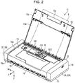
- a liquid ejecting apparatus 11 includes a rectangular box-like casing unit 12 and an opening/closing body 13 mounted on the casing unit 12.
- the opening/closing body 13 includes a rectangular plate-shaped body portion 13a that is joined to be pivotable with respect to the casing unit 12 and a rectangular plate-shape extension portion 13b that is joined such that a base end portion is pivotable with respect to the body portion 13a.
- the extension portion 13b is smaller than the body portion 13a.
- a hand-catch portion 13c is recessed on the front end side of the extension portion 13b.
- the opening/closing body 13 is disposed at a close position illustrated in Fig. 1 and an open position illustrated in Fig. 2 by catching the hand-catch portion 13c with a hand and pivoting the extension portion 13b and the body portion 13a at up to predetermined angles, respectively.
- an insertion opening 14 through which a medium S is inserted into the casing unit 12 and a discharge opening 15 through which the medium S is discharged from the casing unit 12 are exposed.
- the opening/closing body 13 disposed at the open position functions as a support base (sheet feeding tray) supporting the medium S inserted into the insertion opening 14.
- the outer wall to which the insertion opening 14 is opened is referred to as a top wall 16, the outer wall opposite to the top wall 16 is referred to as a bottom wall 17, the outer wall to which the discharge opening 15 is opened is referred to as a front wall 18, and the outer wall opposite to the front wall 18 is referred to as a rear wall 19.
- the side of the top wall 16 is referred to as a top surface side and the side of the bottom wall 17 is referred to as a bottom surface side in some cases.
- a manipulation unit 101 manipulating the liquid ejecting apparatus 11 and a display unit 102 displaying a manipulation result of the manipulation unit 101, an operation status of the liquid ejecting apparatus 11, and the like are disposed on the external surface (top wall) side of the top wall 16.
- a control unit 103 controlling an operation of the liquid ejecting apparatus 11 is disposed on the internal surface (bottom surface) side of the top wall 16.
- the manipulation unit 101 and the display unit 102 are electrically connected to the control unit 103.
- the body portion 13a In the opening/closing body 13 disposed at the close position, the body portion 13a partially overlaps with a part of the top wall 16 so that the insertion opening 14, the manipulation unit 101, and the display unit 102 are covered and the extension portion 13b partially overlaps with the front wall 18 so that the discharge opening 15 is covered.
- Concave portions 16a and 18a accommodating the body portion 13a and the extension portion 13b disposed at the close position are recessed in the top wall 16 and the front wall 18.
- the opening/closing body 13 When the opening/closing body 13 is disposed at the close position, the opening/closing body 13 is accommodated in the concave portions 16a and 18a so that the outside surface thereof are substantially flush with the outside surface of the casing unit 12 to be integrated with the casing unit 12.
- a posture (a posture illustrated in Figs. 1 and 2 ) at which the bottom wall 17 of the liquid ejecting apparatus 11 is mounted to face a mounted surface is referred to as horizontal placing and a posture (a posture illustrated in Fig. 10 ) at which the rear wall 19 is mounted to face the mounted surface is referred to as vertical placing.
- the area of the outer surface of the rear wall 19 is smaller than the area of the outer surface of the bottom wall 17 in the casing unit 12. Therefore, when the liquid ejecting apparatus 11 is mounted at the posture of the vertical placing, the area of the mounted surface becomes small. Therefore, the liquid ejecting apparatus 11 can be used such that the liquid ejecting apparatus 11 is horizontally placed at the time of use and is vertically placed at the time of non-use.
- the liquid ejecting apparatus 11 When support legs 12a (see Figs. 3 , 5 , and 10 ) protrude from the bottom wall 17 and the rear wall 19 which may be contact surfaces to the mounted surface, the posture of the liquid ejecting apparatus 11 can be stabilized at the time of mounting.
- the liquid ejecting apparatus 11 includes the casing unit 12 of which the posture can be changed at the time of the mounting in this way and the opening/closing body 13 which can be integrated with the casing unit 12, and thus can be appropriately used as a portable mobile type liquid ejecting apparatus.
- a transport mechanism 21 that transports the medium S inserted from the insertion opening 14 to the discharge opening 15 and a medium support portion 22 that supports the medium S which is being transported are accommodated in the casing unit 12.
- the transport mechanism 21 includes a transport roller 23 that transports the medium S from the insertion opening 14 to the medium support portion 22 and a discharge roller 24 that transports the medium S from the medium support portion 22 to the discharge opening 15.
- the transport mechanism 21 includes a transport motor 25 which is a driving source and a power transmission mechanism 26 which is formed by a gear train or the like transmitting a driving force of the transport motor 25 to the transport roller 23 and the discharge roller 24.
- the liquid ejecting apparatus 11 includes a liquid ejecting unit 31 that ejects a liquid to the medium S supported by the medium support portion 22 and a carriage 33 that holds the liquid ejecting unit 31 and reciprocates along a guide rail 32 installed in the casing unit 12.
- the liquid ejecting unit 31 includes a plurality of nozzles 34 ejecting the liquid as liquid droplets.
- the liquid ejecting unit 31 ejects the liquid droplets from the nozzles 34 while reciprocating in a movement direction M intersecting a transport direction F of the medium S along with the carriage 33.
- the liquid ejected by the liquid ejecting unit 31 is supplied from a liquid container 104 (see Fig. 10 ) detachably mounted on the carriage 33.
- an ejection direction J in which the liquid droplets are ejected from the nozzles 34 is a direction intersecting both of the transport direction F and the movement direction M.
- the ejection direction J is preferably a vertical downside (gravity direction).
- the side of a first end E1 (the right end in Fig. 3 ) in the movement direction M is set as a home position of the liquid ejecting unit 31.
- the liquid ejecting unit 31 alternately performs forward movement oriented from the first end E1 to a second end E2 (the left end in Fig. 3 ) in the movement direction M and backward movement oriented from the second end E2 to the first end E1.
- the transport motor 25 is disposed at a position closer to the insertion opening 14 than the medium support portion 22 in the transport direction F and at a position closer to the second end E2 than the first end E1 in the movement direction M.
- a plurality of support protrusions 22a supporting the medium S are installed to be arranged in the movement direction M and the transport direction F.
- a sheet accommodation concave portion 22b is installed on the side of the first end E1 in the movement direction M.
- a liquid droplet acceptance sheet 27 capable of absorbing the liquid is accommodated in the sheet accommodation concave portion 22b.
- An absorber 28 capable of absorbing the liquid is disposed between the bottom wall 17 and the sheet accommodation concave portion 22b of the medium support portion 22.
- the absorber 28 is preferably greater than the liquid droplet acceptance sheet 27 in an absorption capacity of the liquid.
- a plurality of openings are installed at positions corresponding to the inner bottom of the sheet accommodation concave portion 22b.
- a plurality of extension portions 27a of which front ends droop via the openings to come into contact with the absorber 28 are installed.
- the liquid droplet acceptance sheet 27 accepts the liquid droplets beyond the margin of the medium S.
- the liquid accepted by the liquid droplet acceptance sheet 27 transitions to the absorber 28 along the extension portions 27a to be absorbed by the absorber 28.
- the liquid ejecting apparatus 11 includes a maintenance mechanism 41 that performs maintenance of the liquid ejecting unit 31.
- the transport mechanism 21 and the guide rail 32 are not illustrated and the medium support portion 22, the carriage 33, and the liquid ejecting unit 31 are indicated by two-dot chain lines.
- the maintenance mechanism 41 is not illustrated.
- the maintenance mechanism 41 includes a cap 42 that is disposed at a position corresponding to the home position in the movement direction M, a suction mechanism 44 that is connected to the cap 42 via a suction tube 43, a ventilation tube 45 of which a base end side is connected to the cap 42, and an atmosphere opening valve 46 that is installed on the front end side of the ventilation tube 45.
- the cap 42 can be moved in the ejection direction J and is moved between a capping position (a position illustrated in Fig. 7 ) at which the cap 42 comes into contact with the liquid ejecting unit 31 located at the home position and an evacuation position closer to the bottom wall 17 than the capping position.
- the cap 42 When the cap 42 is moved to the capping position at which the cap 42 comes into contact with the liquid ejecting unit 31, the cap 42 forms an enclosed space to which the nozzles 34 are opened. Thus, forming the enclosed space to which the nozzles 34 are opened by the cap 42 is referred to as "capping.”
- the capping is released. Then, the liquid ejecting unit 31 is moved to the home position to wait in the capped state at the time of power-off or the like at which the liquid is not ejected.
- the atmosphere opening valve 46 When the atmosphere opening valve 46 is displaced to a valve opening position at which the front end of the ventilation tube 45 is opened, the enclosed space formed by the cap 42 enters a state communicating with the atmosphere. When the atmosphere opening valve 46 is displaced to a valve closing position at which the front end of the ventilation tube 45 is closed, a state in which the enclosed space is enclosed is formed so that the nozzles 34 are prevented from drying.
- the suction mechanism 44 is, for example, a suction pump that is formed by a tube pump or the like generating a suction force by crushing an elastically deformable tube by a pressing member in an eccentric state while being moved rotatably.
- the atmosphere opening valve 46 is located at the valve closing position and the suction mechanism 44 is driven, the enclosed space is depressurized so that a negative pressure is formed.
- suction cleaning of discharging the liquid from the liquid ejecting unit 31 via the nozzles 34 is performed.
- the suction mechanism 44 is formed by the tube pump, the enclosed space can be allowed to communicate with the atmosphere by releasing the crushing of the rube by the pressing member. Therefore, in this case, the atmosphere opening valve 46 and the ventilation tube 45 may not be included.
- the suction cleaning is performed as a maintenance operation to resolve an ejection failure, for example, when the ejection failure of the liquid occurs due to clogging or the like of the nozzles 34. Therefore, the liquid discharged from the nozzles 34 through the suction cleaning is treated as a waste liquid containing solute components or the like of bubbles mixed inside the liquid ejecting unit 31 or the thickened liquid.
- the negative pressure of the enclosed space is released by displacing the atmosphere opening valve 46 to the valve opening position, and then the capping is released by relatively moving the cap 42 in a direction distant from the liquid ejecting unit 31. Thereafter, idle suction is performed to discharge the liquid remaining in the cap 42 by driving the suction mechanism 44.
- the liquid ejecting unit 31 performs flushing in some cases by ejecting liquid droplets toward the cap 42 located at the evacuation position. After the flushing is performed, idle suction is performed to discharge the liquid accepted by the cap 42 by driving the suction mechanism 44.
- the liquid ejecting apparatus 11 includes a mounting unit 52 connected to the suction mechanism 44 via a discharge tube 51.
- the mounting unit 52 is disposed at a position interposed between the medium support portion 22 and the bottom wall 17 in the ejection direction J and a position closer to the second end E2 (the left end in Fig. 4 ) than the absorber 28 in the movement direction M.
- a waste liquid container 81 capable of containing a waste liquid is detachably mounted on the mounting unit 52.
- the liquid (waste liquid) discharged from the liquid ejecting unit 31 to the cap 42 through the suction cleaning or the flushing is contained in the waste liquid container 81 mounted on the mounting unit 52 via the discharge tube 51 with the driving of the suction mechanism 44.
- the cap 42, the absorber 28, the mounting unit 52, and the waste liquid container 81 mounted on the mounting unit 52 are disposed to be arranged sequentially from the first end E1 to the second end E2 in the movement direction M.
- the waste liquid container 81 is moved from the side of the second end E2 to the side of the first end E1 to be mounted on the mounting unit 52 in the liquid ejecting apparatus 11.
- the waste liquid container 81 mounted on the liquid ejecting apparatus 11 is moved from the side of the first end E1 to the side of the second end E2 to be detached (removed) from the mounting unit 52. Therefore, a direction (an opposite direction to the movement direction M) oriented from the second end E2 to the first end E1 is referred to as a mounting direction X of the waste liquid container 81 and a direction (the movement direction M) oriented from the first end E1 to the second end E2 is referred to as a detaching direction of the waste liquid container 81 in some cases.
- one end (the right end in Fig. 4 ) which is the front side (the side on which the waste liquid container 81 is mounted on the mounting unit 52) of the mounting direction X is referred to as a front end and the other end (the left end in Fig. 4 ) which is an opposite side to the one end is referred to as a rear end in some case.
- a direction intersecting the mounting direction X of the waste liquid container 81 is referred to as a width direction Y and a direction intersecting both of the mounting direction X and the width direction Y is referred to as a thickness direction Z.
- the width direction Y is a direction orthogonal to the mounting direction X and is a direction identical to the transport direction F when the waste liquid container 81 is mounted on the mounting unit 52.
- the thickness direction Z is a direction orthogonal to both of the mounting direction X and the width direction Y and is a direction identical to the ejection direction J when the waste liquid container 81 is mounted on the mounting unit 52.
- a waste liquid container accommodation portion 48 that can contain the waste liquid container 81 is recessed to be opened in the ejection direction J (the bottom surface side).
- the length of the waste liquid container accommodation portion 48 in the mounting direction X is longer than the length of the waste liquid container 81 in the mounting direction X.
- a movement guide portion 49 guiding the waste liquid container 81 mounted on or detached from the mounting unit 52 is installed to extend in the mounting direction X.
- Guide protrusions 81a and 81b engaging with the movement guide portion 49 at the time of the mounting on the mounting unit 52 protrude on both of the end sides of the waste liquid container 81 in the width direction Y.
- the positions of the guide protrusions 81a and 81b are different in the thickness direction Z (see Figs. 11A and 11B ).
- the guide protrusion 81a engages with the movement guide portion 49 from the bottom surface side and the guide protrusion 81b engages with the movement guide portion 49 from the top surface side. That is, the waste liquid container 81 is mounted on the mounting unit 52. Therefore, when the waste liquid container 81 is moved in the mounting direction X in the waste liquid container accommodation portion 48, the guide protrusions 81a and 81b engage with the movement guide portion 49, and thus the movement of the waste liquid container 81 in the ejection direction J is suppressed.
- An opening/closing lid 47 including a pair of locking claws 47a is joined to the mounting opening 17a so that the opening/closing lid 47 is pivoted to be opened or closed.
- the waste liquid container 81 When the waste liquid container 81 is accommodated in the waste liquid container accommodation portion 48 from the mounting opening 17a and the waste liquid container 81 is subsequently moved toward the mounting unit 52 in the mounting direction X, the waste liquid container 81 is mounted on the mounting unit 52.
- a finger-catch portion 83 caught by a finger or the like when the waste liquid container 81 is removed from the mounting unit 52 is recessed in the waste liquid container 81.
- the opening/closing lid 47 is opened to release the engagement of the locking protrusion 47b with the movement regulation portion 82 and the waste liquid container 81 is subsequently moved in the detaching direction, for example, by catching the finger-catch portion 83 with a finger.
- the waste liquid container 81 is taken out from the waste liquid container accommodation portion 48 via the mounting opening 17a.
- the waste liquid container 81 is exchanged by mounting and detaching the waste liquid container 81, for example, when a capacity of the waste liquid in the waste liquid container 81 exceeds a regulation capacity.
- the cap 42 includes a cap member 63 in which a first connection protrusion 61 to which the suction tube 43 is connected protrudes and a second connection protrusion 62 to which the ventilation tube 45 is connected protrudes.
- the first connection protrusion 61 and the second connection protrusion 62 are disposed to be arranged in the movement direction M, and the second connection protrusion 62 is disposed at a position closer to the home position than the first connection protrusion 61.
- the cap member 63 includes a bottom portion 64 that extends in the transport direction F and the movement direction M and a side wall portion 65 that intersects the bottom portion 64 and extends in the ejection direction J.
- the bottom portion 64 of the cap member 63 has a substantially rectangular shape of which a longitudinal direction is the transport direction F and a transverse direction is the movement direction M in a plan view.
- a third side wall 65c a part thereof on a second end side (the left side in Fig. 7 ) in the movement direction M is referred to as a fourth side wall 65d, the side walls 65c and 65d are longer than the side walls 65a and 65b.
- the first connection protrusion 61 and the second connection protrusion 62 protrude in the transport direction F to project from the second side wall 65b.
- the bottom portion 64 and the side wall portion 65 of the cap member 63 form a liquid storage portion 66 that can store a liquid.
- An elastically deformable lip portion 67 with a circular shape is joined to the front end of the side wall portion 65 of the cap member 63.
- the lip portion 67 is elastically deformed to come into close contact with the liquid ejecting unit 31, and thus the degree of close contact of the enclosed space increases.
- the cap member 63 includes a discharge hole 68 formed to penetrate through the first connection protrusion 61 and the second side wall 65b. That is, the discharge hole 68 communicating with the suction tube 43 is formed in the cap member 63.
- a ventilation passage formation portion 65e protrudes at a position corresponding to the second connection protrusion 62 of the second side wall 65b to project to the liquid storage portion 66.
- the cap member 63 includes a ventilation hole 69 formed to penetrate through the second connection protrusion 62, the second side wall 65b, and the ventilation passage formation portion 65e.
- a groove 71 communicating with the discharge hole 68 and extending the longitudinal direction of the bottom portion 64 is recessed in the bottom portion 64 of the cap member 63.
- an upstream end of the groove 71 forms a substantially circular shape in a plan view and is located near the middle of the bottom portion 64 in the longitudinal direction (the transport direction F) and the transverse direction (the movement direction M).
- the ventilation hole 69 is opened at a position closer to the discharge hole 68 than the upstream end of the substantially circular shape of the groove 71 in a plan view and a position distant from the bottom portion 64.
- a plurality of support shafts 72 protrude in the longitudinal direction (the transport direction F).
- the upstream end forming the circular shape of the groove 71 in a plan view is disposed between the two support shafts 72 in the longitudinal direction of the bottom portion 64.
- the groove 71 is wound to avoid the support shafts 72.
- a sheet-shaped member 73 with flexibility overlaps with the bottom portion 64 to cover the groove 71 in the liquid storage portion 66 of the cap 42.
- a suction hole 73a is formed at a position at which the suction hole 73a overlaps with the upstream end of the groove 71.
- through holes 73b are formed so that the support shafts 72 are inserted inside the liquid storage portion 66.
- a notch 73c is formed at a position corresponding to the ventilation passage formation portion 65e.
- liquid absorbers 74 and 75 capable of absorbing a liquid are accommodated to overlap in a layer shape with the sheet-shape member 73 interposed between the bottom portion 64 and the liquid absorbers 74 and 75.
- through holes 74b and 75b through which the support shaft 72 can be inserted in the liquid storage portion 66 are formed, respectively.
- notches 74c and 75c are formed at positions corresponding to the ventilation passage formation portion 65e.
- the liquid absorber 74 disposed on the side of the sheet-shaped member 73 is formed of a porous material and the liquid absorber 75 disposed on the side of the lip portion 67 is formed of a non-woven fabric.
- a plurality of holes formed inside the liquid absorber 74 formed of the porous material are continuous holes communicating with each other and preferably have high affinity to the liquid stored in the liquid storage portion 66.
- the liquid absorber 74 is formed of an elastic body with higher compressive elastic modulus than the liquid absorber 75 and the cap member 63.
- the two kinds of liquid absorbers 74 and 75 formed of different materials are accommodated in the liquid storage portion 66, but liquid absorbers formed of any one kind of material may be accommodated. Liquid absorbers formed of materials different from the materials exemplified in the embodiment may be adopted.
- the cap 42 preferably includes a pressure member 76 pressing the sheet-shaped member 73 via the liquid absorbers 74 and 75.
- the pressure member 76 can be formed of, for example, a metal in a netlike shape so that the outside surface of the liquid absorber 75 is broadly exposed while uniformly pressing the outside surface which is a surface on the side of the lip portion 67 of the liquid absorber 75.
- the pressure member 76 includes an insertion hole 76b through which the front end of the support shaft 72 can be inserted.
- the pressure member 76 is fixed to the cap member 63 by crushing the front end of the support shaft 72 inserted into the insertion hole 76b and forming the front end in a hemisphere shape, as illustrated in Fig. 7 .
- the pressure member 76 is preferably maintained in a state in which the pressure member 76 presses the liquid absorbers 74 and 75 inside the liquid storage portion 66 to compress and deform the liquid absorbers 74 and 75.
- the liquid absorber 74 compressed and deformed more easily (smoothly) than the liquid absorber 75 is compressed and deformed at a higher compression ratio than the liquid absorber 75 through the pressing of the pressure member 76.
- Ha + Lc ⁇ Lb is preferably satisfied when Ha is a liquid level height of the liquid which can be absorbed by capillary forces of the liquid absorbers 74 and 75, Lb is the length of the bottom portion 64 in the extension direction (the transport direction F which is the longitudinal direction of the bottom portion 64 in the embodiment) of the discharge hole 68, and Lc is the distance between the discharge hole 68 and the suction hole 73a in the extension direction.
- the suction hole 73a is disposed to overlap with the upstream end of the groove 71, the distance Lc between the discharge hole 68 and the suction hole 73a is substantially identical to the length of the groove 71 in the extension direction.
- the density of the liquid absorber 74 which is a foam body foamed by minutely dispersing a gas of a synthetic resin of urethane, polyvinyl alcohol, or the like, is in the range of 0.023 g/cm 3 to 0.099 g/cm 3 and the diameter of the hole (bubble) is in the range of about 200 micrometers to about 300 micrometers, the ink can be sucked and raised by about 15 mm to 25 mm by the capillary force of the continuous holes communicating with each other.
- the liquid absorber 75 formed of a non-woven fabric can suck and raise the ink by approximately 20 mm by the capillary force of a gap between fibers when the density is in the range of 0.065 g/cm 3 to 0.175 g/cm 3 and the gap between fibers is about 70 micrometers. It can be said that the capability to maintain the liquid of the liquid absorber is higher as the value of the liquid level height Ha of the liquid which can be absorbed by the capillary force is larger.
- the liquid level height Ha of the liquid which can be absorbed by the capillary force by the liquid absorber 74 is about 15 mm.
- the liquid level height Ha of the liquid which can be absorbed by the capillary force by the liquid absorber 75 is about 23 mm.
- the discharge hole 68 is formed to penetrate through the side wall portion 65 in the cap member 63 included in the cap 42, the first connection protrusion 61 protrudes toward the lateral side (in the longitudinal direction of the cap member 63) used to connect the suction tube 43. Therefore, the cap 42 can be reduced in size (thinned) in the ejection direction J further than when the first connection protrusion projects from the bottom portion 64 in the ejection direction J.
- the cap 42 By protruding the second connection protrusion 62 forming the ventilation hole 69 toward the second side wall 65b in the same direction as that of the first connection protrusion 61, the cap 42 can be reduced in size further than when the first connection protrusion 61 and the second connection protrusion 62 protrude in different directions.
- the liquid ejecting apparatus 11 it is preferable to reduce the area of the mounted surface necessary to vertically placing the liquid ejecting apparatus 11, as illustrated in Fig. 10 . From this viewpoint, the area of the mounted surface necessary to vertically place the liquid ejecting apparatus 11 can be reduced by thinning the cap 42 (reducing the size of the cap 42 in the ejection direction J) and thinning the liquid ejecting apparatus 11.
- a passage communicating with the discharge hole 68 is formed by the sheet-shaped member 73 and the groove 71 recessed by the bottom portion 64. Therefore, when the suction mechanism 44 is driven, the inside of the liquid storage portion 66 is sucked via the suction hole 73a and the discharge hole 68 formed in the sheet-shaped member 73.
- the cap 42 and the liquid ejecting apparatus 11 can be thinned further than when the groove 71 is covered with a plate or the like.
- the sheet-shaped member 73 covering the groove 71 is thinned, the sheet-shaped member 73 is easily bent at the time of driving of the suction mechanism 44. Therefore, it is possible to remove the gap between the bottom portion 64 (the bottom surface forming the liquid storage portion 66) and the sheet-shaped member 73 and sucking the inside of the liquid storage portion 66 effectively.
- the liquid absorber 74 with high compressive elastic modulus is disposed to be compressed and deformed at a position at which the liquid absorber 74 comes into contact with the sheet-shaped member 73, the sheet-shaped member 73 is tightly pressed against the bottom portion 64 by an elastic restoration force of the liquid absorber 74.
- the liquid discharged from the nozzles 34 and thus the liquid droplets adhered to the liquid ejecting unit 31 remain in some cases.
- the liquid absorber 75 present on the side of the lip portion 67 has a function of removing the liquid droplets from the liquid ejecting unit 31 by touching and absorbing the liquid droplets adhered to the liquid ejecting unit 31.
- the liquid absorber 75 when the enclosed space is formed by the cap 42, it is necessary dispose the liquid absorber 75 at a position close to the liquid ejecting unit 31.
- the liquid absorber 75 absorbs the liquid and expands, there is a concern of a liquid surface (meniscus) formed in the nozzles 34 being disturbed due to touch to the nozzles 34. Therefore, the liquid absorber 75 located on the side of the lip portion 67 is preferably deformed small by absorption of the liquid or the like.
- the liquid absorber 74 with a large elastic deformation ratio is disposed on the side of the sheet-shaped member 73 and the liquid absorber 75 with a small deformation ratio is disposed on the side of the lip portion 67, the contact of the liquid absorber 75 to the nozzles 34 can be suppressed while the sheet-shaped member 73 is pressed against the bottom portion 64 by the liquid absorber 74. Even when only the hardly deformable liquid absorber 75 is accommodated in the liquid storage portion 66, the liquid absorber 75 is pressed by the pressure member 76 so that the sheet-shaped member 73 can be pressed against the bottom portion 64.
- the bottom portion 64 of the cap member 63 is formed in the substantially rectangular shape in a plan view and the discharge hole 68 is installed in the second side wall 65b which is the short side. Therefore, when the liquid storage portion 66 is sucked directly from the discharge hole 68, it is difficult that the suction force to affect the side of the first side wall 65a. From this point, in the cap member 63, the discharge hole 68 is installed in the side wall portion 65, but the discharge hole 68 communicates with the suction hole 73a disposed near the middle of the bottom portion 64 via the groove 71. Therefore, when the suction mechanism 44 is driven, the liquid absorbed by the liquid absorbers 74 and 75 is sucked from the vicinity of the middle of the bottom portion 64.
- the second side wall 65b, the discharge hole 68, and the ventilation hole 69 in the cap 42 are disposed vertically upward the liquid storage portion 66, and the first connection protrusion 61 and the second connection protrusion 62 are at the posture in the vertical direction at which the first connection protrusion 61 and the second connection protrusion 62 project vertically upward from the second side wall 65b.
- the liquid maintaining force of the liquid absorbers 74 and 75 is small and the cap 42 takes the posture in the vertical direction, it is difficult to suck the liquid located vertically downward more than the suction hole 73a.
- the value of Ha of the liquid absorber 74 is smaller than that of the liquid absorber 75 and Ha is set to be 15 mm in that the liquid absorber 74 is disposed at a position which the liquid absorber 74 comes into contact with the sheet-shaped member 73.
- Lc is the value which is substantially the same as 1/2Lb.
- the capping is performed in a state in which the liquid retains inside the liquid storage portion 66 in order to prevent the nozzles 34 from drying. Therefore, when the ventilation hole 69 is located on the vertical downside inside the liquid storage portion 66, there is a concern of the liquid flowing in the ventilation hole 69 to be clogged and the liquid being leaking. From this viewpoint, by opening the ventilation hole 69 to the side of the second side wall 65b and the position distant from the bottom portion 64, the liquid can be prevented from flowing in the ventilation hole 69 at either posture of the vertical placing or the horizontal placing.
- the capping when the capping is released in the state in which the liquid ejecting apparatus 11 is vertically placed, there is a concern of the liquid being leaking in the liquid storage portion 66 and the inside of the casing unit 12 being staining.
- the liquid ejecting apparatus 11 includes a detection unit 77 that detects the posture of the casing unit 12 and the detection unit 77 detects that the posture of the casing unit 12 is vertically placed,.
- a predetermined operation such as a liquid ejecting operation (printing, flushing, or the like), a maintenance operation for the nozzles 34, or exchange of the liquid container 104, by which the inside of the casing unit 12 stains due to leakage of the liquid.
- the liquid ejecting apparatus 11 includes a medium sensor (not illustrated) detecting that the medium S is inserted into the insertion opening 14, the medium sensor detects the medium S, and the detection unit 77 detects that the posture of the casing unit 12 is the vertical placing.
- the medium sensor detects the medium S and the detection unit 77 detects that the posture of the casing unit 12 is the vertical placing, the medium S may be prevented from being fed by increasing a motor toque of the transport motor 25 which is the driving source.
- the detection unit 77 may be disposed at any position inside the casing unit 12. Of the positions inside the casing unit 12, the detection unit 77 is preferably disposed at a position on a member to which a vibration source generating proper vibration is joined.
- the detection unit 77 is fixed to the suction mechanism 44 inside the casing unit 12. At the time of the driving of the suction mechanism 44, proper vibration is transferred to the detection unit 77. Therefore, when the detection unit 77 that uses a spindle rolling by the force of gravity is used, a detection failure caused due to adhering after long-term storage can be suppressed according to, for example, a method of driving the suction mechanism 44 before detection and performing the detection.
- a threshold value of the inclination angle at which the operation is restricted may be arbitrarily changed according to, for example, the height (the length in the ejection direction J) of the side wall portion 65 and the liquid maintaining forces of the liquid absorbers 74 and 75.
- the liquid ejecting operation (the printing, the flushing, or the like) is performed without performing the capping and the inclination angle exceeds a predetermined threshold, it is preferable to stop the liquid ejecting operation and the feeding operation for the medium S or increase the motor torque of the transport motor 25.
- the liquid ejecting apparatus 11 includes a storage cell and an operation is possible with the power of the storage cell, there is a concern that a manipulation button or the like is pushed erroneously without intention in the middle of carrying of the liquid ejecting apparatus 11, and thus, for example, the capping is released or the liquid is ejected. Therefore, when the liquid ejecting apparatus 11 includes a storage cell, in particular, it is preferable to restrict an operation due to the detection of the inclined angle.
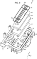
- connection concave portion 53 opened in the detaching direction (the opposite direction to the mounting direction X) and the thickness direction Z is recessed in the mounting unit 52.
- a connection hole 56 communicating with the discharge tube 51 is formed in the discharge portion 55.
- a substrate connection portion 57 electrically connected to the control unit 103 (see Fig. 2 ) is provided to the projection 54.
- the substrate connection portion 57 includes a movable contact portion 57a which can be elastically displaced by a contact pressure.
- the movable contact portion 57a projects from the projection 54 in the thickness direction Z when an external force is not received, and the movable contact portion 57a is elastically displaced in a direction close to the projection 54 when an external force is received.
- the projection 54 includes a pair of engaging projection 58 formed to project in the width direction Y.
- the pair of engaging projections 58 is disposed at positions at which the substrate connection portion 57 is interposed therebetween in the width direction Y.
- the substrate connection portion 57 projects more than the engaging projections 58 in the detaching direction, and the engaging projections 58 protrude more than the substrate connection portion 57 in the thickness direction Z.
- an concave portion is recessed which has engaging surfaces 58a and 58c extending in the mounting direction X and the width direction Y and facing each other, an engaging surface 58b extending in the mounting direction X and the thickness direction Z and intersecting the engaging surfaces 58a and 58c.
- the engaging surface 58a faces in the thickness direction Z and the engaging surface 58c faces in the opposite direction to the thickness direction Z.
- a front end surface 58d of the engaging projection 58 intersecting the engaging surfaces 58a, 58b, and 58c extends in the width direction Y and the thickness direction Z.
- the center of the connection hole 56 is located on a plane (which is an imaginary surface indicated by a one-dot chain line in Fig. 11B ) including the engaging surface 58c.
- Fig. 12 is an exploded perspective view illustrating the waste liquid container 81.
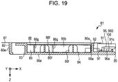
- Figs. 13 to 18 are diagrams illustrating the outer appearance of the waste liquid container 81.
- L 1 is the length of the waste liquid container 81 in the mounting direction X
- L2 is the length of the waste liquid container 81 in the width direction Y
- L3 is the length (thickness) of the waste liquid container 81 in the thickness direction Z
- L1 > L2 > L3 is satisfied. That is, the waste liquid container 81 has an externally thin shape of which a longitudinal direction is the mounting direction X and of which a length in the thickness direction Z is short. Therefore, the waste liquid container 81 is properly mounted on the thin liquid ejecting apparatus 11.
- the waste liquid container 81 includes an absorber 84 which can absorb the waste liquid, an accommodation member 86 which has a box-like shape with a bottom and in which an accommodation concave portion 85 capable of accommodating the absorber 84, a film member 87 which covers an opening of the accommodation concave portion 85, and a reinforcement member 88 which is disposed between the absorber 84 and the sheet-shaped member 73.
- the reinforcement member 88 is a member that has higher rigidity than the film member 87.
- the accommodation member 86 includes a bottom wall portion 86a which forms an inner bottom surface of the accommodation concave portion 85, a pair of side wall portions 86b and 86c which extends in the mounting direction X and the thickness direction Z and intersects the bottom wall portion 86a, and a front wall portion 86d and a rear wall portion 86e which intersect the wall portions 86a, 86b, and 86c.
- the accommodation concave portion 85 is formed by the wall portions 86a, 86b, 86c, 86d, and 86e and a containing portion 89 capable of containing the waste liquid is surrounded to be formed by the accommodation concave portion 85 and the film member 87.
- An atmosphere communication hole 87a communicating the containing portion 89 with the atmosphere is formed in the film member 87.
- the number of atmosphere communication holes 87a or the position of the atmosphere communication hole 87a can be changed arbitrarily.
- the accommodation member 86 includes a convex portion 91 projecting from the containing portion 89 in the mounting direction X in one end (front end) thereof in the mounting direction X. Both ends of the convex portion 91 in the width direction Y are disposed more inside in the width direction Y than the side wall portions 86b and 86c formed at both ends of the containing portion 89 in the width direction Y. A notch 81c formed by notching one corner in the width direction Y is formed at the other end (rear end) of the accommodation member 86 in the mounting direction X.
- the guide protrusions 81a and 81b protrude to the side wall portions 86b and 86c of the accommodation member 86 to project toward the outside in the width direction Y.
- the guide protrusion 81b is disposed at a position closer to the film member 87 than the guide protrusion 81a in the thickness direction Z.
- the guide protrusion 81a is disposed at a position closer to the convex portion 91 than the guide protrusion 81b in the mounting direction X.
- a connection concave portion 92 opened in the opposite direction to the thickness direction Z and the mounting direction X and a waste liquid introduction portion 93 extending in the mounting direction X are formed to be arranged in the width direction Y.
- the end of the waste liquid introduction portion 93 in the detaching direction communicates with the containing portion 89 and the end of the waste liquid introduction portion 93 in the mounting direction X is opened to the front end surface of the convex portion 91.
- the waste liquid introduction portion 93 includes an insertion opening 93a opened in the mounting direction X.
- the insertion opening 93a of the waste liquid introduction portion 93 is covered with a film 94.
- a cross-shaped incision 94a is formed in the film 94.
- a part of the wall surface of the waste liquid introduction portion 93 is formed by the film member 87.
- the convex portion 91 includes a first wall portion 91a which is formed to extend from the bottom wall portion 86a, a second wall portion 91b which intersects the first wall portion 91a and forms a part of the wall surface of the waste liquid introduction portion 93, a third wall portion 91c which intersects the first wall portion 91a and is disposed at a position confronting the second wall portion 91b, and a fourth wall portion 91d (see Fig. 20 ) which forms a part of the wall surface of the waste liquid introduction portion 93.
- the wall portions 91a, 91b, and 91c and the front wall portion 86d form the connection concave portion 92.
- connection terminals 95 are joined to be located inside the connection concave portion 92.
- the circuit substrate 100 includes a memory element that stores information such as the capacity of waste liquid contained in the containing portion 89.
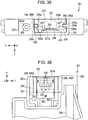
- a pair of guide portions 96 (96F and 96S) are formed so that the connection terminals 95 are interposed therebetween in the width direction Y.
- one guide portion 96F protrudes to the second wall portion 91b to project toward the inside of the connection concave portion 92 and the other guide portion 96S protrudes to the third wall portion 91c to project toward the inside of the connection concave portion 92. That is, at one end (front end) of the accommodation member 86, the guide portion 96F is disposed between the connection terminals 95 and the waste liquid introduction portion 93 in the width direction Y.
- one pair of guide portions 96 each includes a guide surface 96a extending in the mounting direction X and the width direction Y.
- the guide surface 96a is oriented in the opposite direction (the thickness direction Z) to the connection terminals 95.
- An opening center (the center of the insertion opening 93a and the incision 94a) of the waste liquid introduction portion 93 is located on a plane (which is an imaginary surface indicated by a one-dot chain line in Fig. 17 ) including the two guide surfaces 96a.
- a pair of regulation protrusions 97 projecting in the mounting direction X more than the front wall portion 86d is formed on the inner rear side of the connection concave portion 92 more than the connection terminals 95. As illustrated in Fig. 12 , the regulation protrusions 97 are located between the guide portions 96 and the front wall portion 86d in the mounting direction X.
- the accommodation member 86 includes a plurality of protrusions 86f and 86g projecting inside the containing portion 89.
- the protrusions 86f formed in a cross shape in a front view protrude from the bottom wall portion 86a and the protrusions 86g formed in a plate shape protrude from the side wall portions 86b and 86c.
- the lengths of the protrusions 86f and 86g in the thickness direction Z are shorter than those of the side wall portions 86b and 86c and the ends of the protrusions 86f and 86g in the thickness direction Z come into contact with the bottom wall portion 86a.
- the absorber 84 has a plate shape of which a length in the thickness direction Z is slightly shorter than the protrusions 86f and 86g and has insertion portions 84a and 84b into which the protrusions 86f and 86g are inserted.
- the protrusions 86f and 86g are inserted into the insertion portions 84a and 84b so that movement in the mounting direction X and the width direction Y inside the containing portion 89 is suppressed.
- a notch 84c corresponding to the notch 81c and a notch concave portion 84d corresponding to the finger-catch portion 83 are formed at the rear end of the absorber 84.
- An extension portion 84e accommodated at the rear end of the waste liquid introduction portion 93 is formed at the front end of the absorber 84.
- the extension portion 84e is not disposed near the insertion opening 93a of the waste liquid introduction portion 93 and a gap is formed between the insertion opening 93a and the extension portion 84e inside the waste liquid introduction portion 93.
- the reinforcement member 88 includes a body portion 88f which covers the surface of the absorber 84 on the side of the film member 87, a first locking portion 88a which is locked in the front end of the absorber 84, and a pair of second locking portions 88b which is locked in the rear end of the absorber 84.
- the first locking portion 88a engages with the front end of the absorber 84 and the second locking portions 88b engage with the rear end of the absorber 84 so that movement in the mounting direction X in the containing portion 89 is suppressed.
- the reinforcement member 88 is preferably formed of a sheet-shaped resin material, but may be formed of, for example, a metal material in a plate shape or a netlike shape.
- the first locking portion 88a and the second locking portions 88b can be formed to be integrated with the body portion 88f by bending the front end and the rear end of the reinforcement member 88 in the thickness direction Z.
- a notch 88C corresponding to the notch 81c and a first notch concave portion 88d corresponding to the finger-catch portion 83 are formed.
- a second notch concave portion 88e is formed at a position corresponding to the inner bottom of the first notch concave portion 88d.
- the second notch concave portion 88e is located between the absorber 84 and the atmosphere communication hole 87a of the film member 87 and communicates with the atmosphere communication hole 87a and the containing portion 89. Therefore, for example, the reinforcement member 88 is formed in a netlike shape, the second notch concave portion 88e may not be formed in the reinforcement member 88.
- the reinforcement member 88 is formed of a material with high rigidity and the lengths of the first locking portion 88a and the second locking portions 88b are longer than that of the absorber 84 in the thickness direction Z, the body portion 88f is supported by the first locking portion 88a and the second locking portions 88b. Therefore, in this case, the protrusions 86f and 86g may not be formed in the accommodation member 86.
- connection concave portion 92 of the waste liquid container 81 is opened in the mounting direction X and is formed at one end (front end) of the waste liquid container 81 in the mounting direction X to be opened in the mounting direction X and insertable into the projection 54 at the time of the mounting on the mounting unit 52.
- connection concave portion 53 of the mounting unit 52 is opened in the detaching direction to be insertable into the convex portion 91 formed at the one end of the waste liquid container 81.
- Fig. 21 illustrates the waste liquid container 81 mounted on the mounting unit 52.
- connection concave portion 92 guides the projection 54 so that the positions of the connection terminals 95 are aligned with the substrate connection portion 57 and the position of the waste liquid introduction portion 93 is aligned with the discharge portion 55.
- the guide portions 96 are inserted into the concave portion formed by the engaging surfaces 58a, 58b, and 58c of the engaging projection 58 formed in the projection 54.
- the guide portions 96 formed in a convex shape are moved in the mounting direction X along the engaging surfaces 58a, 58b, and 58c formed in a concave shape so that the guide surfaces 96a of the guide portions 96 face the engaging surface 58c.
- the guide portions 96 are directly moved in the mounting direction X so that the movement in the opposite direction to the thickness direction Z is suppressed by the engaging surface 58a, the movement in the thickness direction Z is suppressed by the engaging surface 58c, and the movement in the width direction Y is suppressed by the engaging surface 58b.
- one pair of guide portions 96 is formed with the connection terminals 95 therebetween in the width direction Y
- the projection 54 is guided by one pair of guide portions 96 so that the positions of the connection terminals 95 can be aligned with the substrate connection portion 57.
- the one guide portion 96F is disposed between the connection terminals 95 and the waste liquid introduction portion 93 in the width direction Y, the projection 54 is guided by the guide portion 96F so that the position of the waste liquid introduction portion 93 can be aligned with the discharge portion 55.
- the position alignment of the connection terminals 95 to the substrate connection portion 57 and the position alignment of the waste liquid introduction portion 93 to the discharge portion 55 are performed by one pair of guide portions 96.
- the front end surface 58d of the engaging projection 58 and the regulation protrusions 97 function as a positioning unit that stops the waste liquid container 81 moved in the mounting direction X at the mounted position.
- the movement of the waste liquid container 81 in the mounting direction X can also be regulated by causing the projection 54 to collide with the front wall portion 86d without forming the regulation protrusions 97.
- the regulation protrusions 97 and the engaging projections 58 are formed to decrease a contact area of the waste liquid container 81 and the projection 54, accuracy of the positioning is improved.
- connection terminals 95 it is preferable to dispose the connection terminals 95 so that the connection terminals 95 face a region AR (indicated by a two-dot chain line in Fig. 23 ) between the one guide portion 96F and the other guide portion 96S of the one pair of guide portions 96.
- region AR indicated by a two-dot chain line in Fig. 23
- the positions of the connection terminals 95 can be accurately aligned with the substrate connection portion 57 more than when the region AR and the connection terminals 95 are distant in the mounting direction X.
- the movable contact portion 57a of the substrate connection portion 57 comes into contact with the connection terminals 95 by a predetermined contact pressure to be elastically displaced and the connection terminals 95 are electrically connected to the substrate connection portion 57.
- the circuit substrate 100 is electrically connected to the control unit 103, and thus information regarding the capacity or the like of the waste liquid can be transmitted between the circuit substrate 100 and the control unit 103.
- the guide surface 96a of the one pair of guide portions 96 engages with the engaging surface 58c formed in the projection 54 by an elastic restoration force of the movable contact portion 57a pressed and elastically displaced by the connection terminals 95. Therefore, the connection terminals 95 are also moved in the direction distant from the substrate connection portion 57 by the elastic restoration force of the movable contact portion 57a and the guide surface 96a engages with the engaging surface 58c so that the movement of the connection terminals 95 is suppressed. As a result, the state in which the connection terminals 95 come into contact with the movable contact portion 57a by a predetermined contact pressure is maintained.
- connection terminals 95 are disposed in parallel to a plane (which is an imaginary surface indicated by a one-dot chain line in Fig. 22 ) including one pair of guide surfaces 96a to form a plane, contact pressures with the plurality of movable contact portions 57a projecting in the thickness direction become uniform.
- the center of the connection hole 56 is located on the plane (which is the imaginary surface indicated by the one-dot chain line in Fig. 22 ) including two engaging surfaces 58c, and the opening center of the waste liquid introduction portion 93 is located on the plane (which is the imaginary surface indicated by the one-dot chain line in Fig. 22 ) including the two guide surfaces 96a. Therefore, when the waste liquid container 81 is moved to the mounted position, the engaging surface 58c and the guide surface 96a facing each other come into contact with each other by the elastic restoration force of the movable contact portion 57a so that the center position of the connection hole 56 and the center position of the waste liquid introduction portion 93 are disposed on the same plane.
- the center position of the connection hole 56 matches the center position of the waste liquid introduction portion 93 in the thickness direction Z, the positions of the waste liquid introduction portion 93 and the discharge portion 55 can be aligned more accurately, and then the discharge portion 55 can be inserted into the waste liquid introduction portion 93.
- the discharge portion 55 With the movement of the waste liquid container 81 to the mounted position, the discharge portion 55 is inserted into the waste liquid introduction portion 93 via the incision 94a and the insertion opening 93a so that the discharge portion 55 and the waste liquid introduction portion 93 are connected to each other. Thus, the waste liquid discharged from the discharge portion 55 can be introduced to the waste liquid container 81.
- a gap formed between the insertion opening 93a and the extension portion 84e is disposed inside the waste liquid introduction portion 93.
- the containing portion 89 communicates with the atmosphere via the atmosphere communication hole 87a. Therefore, when the waste liquid is introduced into the containing portion 89 via the discharge portion 55, the air corresponding to the capacity of the introduced waste liquid is discharged out of the containing portion 89 via the atmosphere communication hole 87a.
- a concave portion serving as an air passage may be formed from the position corresponding to the atmosphere communication hole 87a formed in the waste liquid container 81 in a direction distant from the circuit substrate 100.
- the waste liquid introduction portion 93 when the waste liquid introduction portion 93 is mounted on the mounting unit 52, the waste liquid is introduced into the waste liquid introduction portion 93 from the side of the absorber 28 which is the side of the first end E1 of the movement direction M to the second end E2.
- the atmosphere communication hole 87a is disposed on the side of the second end E2 distant from the absorber 28 more than the waste liquid introduction portion 93. That is, in the embodiment, since the waste liquid introduction portion 93 and the atmosphere communication hole 87a are located at the positions distant in the inflow direction (the movement direction M) of the waste liquid, the waste liquid can smoothly disperse in the longitudinal direction (the movement direction M) of the absorber 84.
- Information regarding the amount of waste liquid introduced from the discharge portion 55 to the waste liquid container 81 is transmitted from the control unit 103 to the circuit substrate 100 and is stored in the memory element included in the circuit substrate 100.
- the control unit 103 reads the capacity of waste liquid stored in the memory element included in the circuit substrate 100 at a predetermined timing and the capacity of waste liquid reaches a given value, the control unit 103 displays, for example, the fact that the capacity of waste liquid reaches the given value on the display unit 102 to prompt the user to exchange the waste liquid container 81.
- the reinforcement member 88 is disposed between the film member 87 and the protrusions 86f and 86g. Therefore, even when the portion of the film member 87 is pressed, the reinforcement member 88 and the protrusions 86f and 86g receive the pressing force, so that the compression and the deformation of the absorber 84 is suppressed. Thus, the leakage of the waste liquid from the waste liquid container 81 is suppressed.
- the waste liquid introduction portion 93 and the connection terminals 95 are arranged in the width direction Y. Therefore, even when the waste liquid container 81 is disposed or mounted so that the thickness direction Z is the gravity direction and the waste liquid leaks from the waste liquid introduction portion 93, the leaking waste liquid is rarely adhered to the connection terminals 95. Therefore, for example, when the waste liquid container 81 is detached from the liquid ejecting apparatus 11 during the use and the waste liquid container 81 during the use is mounted on the liquid ejecting apparatus 11 again, occurrence of a contact failure of the connection terminals 95 and the substrate connection portion 57 caused due to the adhering of the waste liquid to the connection terminals 95 is suppressed.
- the liquid ejecting apparatus is, for example, an ink jet printer that performs recording (printing) by ejecting ink which is an example of a liquid to a medium such as a sheet.
- a liquid ejecting apparatus 211 includes a rectangular box-like casing unit 212, an opening/closing body 213 mounted on the casing unit 212, and a waste liquid containing unit 310 disposed on a side surface of the casing unit 212.
- the opening/closing body 213 includes a rectangular plate-shaped body portion 213a that is joined to be pivotable with respect to the casing unit 212 and a rectangular plate-shape extension portion 213b that is joined such that a base end portion is pivotable with respect to the body portion 213a.
- the extension portion 213b is smaller than the body portion 213a.
- a hand-catch portion 213c is recessed on the front end side of the extension portion 213b.
- the opening/closing body 213 is disposed at a close position illustrated in Fig. 24 and an open position illustrated in Fig. 25 by catching the hand-catch portion 213c with a hand and pivoting the extension portion 213b and the body portion 213a at up to predetermined angles, respectively.
- an insertion opening 214 through which a medium S is inserted into the casing unit 212 and a discharge opening 215 through which the medium S is discharged from the casing unit 212 are exposed.
- the opening/closing body 213 disposed at the open position functions as a support base (sheet feeding tray) supporting the medium S inserted into the insertion opening 214.
- the outer wall to which the insertion opening 214 is opened is referred to as a top wall 216
- the outer wall opposite to the top wall 216 is referred to as a bottom wall 217
- the outer wall to which the discharge opening 215 is opened is referred to as a front wall 218, and the outer wall opposite to the front wall 218 is referred to as a rear wall 219.
- a pair of outer walls intersecting the top wall 216, the bottom wall 217, the front wall 218, and the rear wall 219 is referred to as outside walls 220.
- the side of the top wall 216 is referred to as a top surface side and the side of the bottom wall 217 is referred to as a bottom surface side in some cases.
- a manipulation unit 261 manipulating the liquid ejecting apparatus 211 and a display unit 262 displaying a manipulation result of the manipulation unit 261, an operation status of the liquid ejecting apparatus 211, and the like are disposed on the external surface (top wall) side of the top wall 216.
- a control unit 263 controlling an operation of the liquid ejecting apparatus 211 is disposed on the internal surface (bottom surface) side of the top wall 216.
- the manipulation unit 261 and the display unit 262 are electrically connected to the control unit 263.
- the body portion 213a partially overlaps with a part of the top wall 216 so insertion opening 214, the manipulation unit 261, and the display unit 262 are covered and the extension portion 213b partially overlaps with the front wall 218 so that the discharge opening 215 is covered.
- Concave portions 216a and 218a accommodating the body portion 213a and the extension portion 213b disposed at the close position are recessed in the top wall 216 and the front wall 218.
- the opening/closing body 213 When the opening/closing body 213 is disposed at the close position, the opening/closing body 213 is accommodated in the concave portions 216a and 218a so that the outside surface thereof are substantially flush with the outside surface of the casing unit 212 to be integrated with the casing unit 212.
- a transport mechanism 221 that transports the medium S inserted from the insertion opening 214 to the discharge opening 215 and a medium support portion 222 that supports the medium S which is being transported are accommodated in the casing unit 212.
- a part of the configuration is not illustrated to facilitate understanding of description of the configuration related to liquid ejection.
- the transport mechanism 221 includes a transport roller 223 that transports the medium S from the insertion opening 214 to the medium support portion 222 and a discharge roller 224 that transports the medium S from the medium support portion 222 to the discharge opening 215.
- the transport mechanism 221 includes a transport motor 225 which is a driving source and a power transmission mechanism 226 which is formed by a gear train or the like transmitting a driving force of the transport motor 225 to the transport roller 223 and the discharge roller 224.
- the liquid ejecting apparatus 211 includes a liquid ejecting unit 231 that ejects a liquid to the medium S supported by the medium support portion 222 and a carriage 233 that holds the liquid ejecting unit 231 and reciprocates along a guide rail 232 installed in the casing unit 212.
- the liquid ejecting unit 231 includes a plurality of nozzles 234 ejecting the liquid as liquid droplets.
- the liquid ejecting unit 231 ejects the liquid droplets from the nozzles 234 while reciprocating in a movement direction M intersecting a transport direction F of the medium S along with the carriage 233.
- the liquid ejected by the liquid ejecting unit 231 is supplied from a liquid container (not illustrated) (for example, an ink cartridge) detachably mounted on the carriage 233.
- a liquid container for example, an ink cartridge
- an ejection direction J in which the liquid droplets are ejected from the nozzles 234 is a gravity direction intersecting both of the transport direction F and the movement direction M.
- the side of a first end E1 (the right end in Fig. 26 ) in the movement direction M is set as a home position of the liquid ejecting unit 231.
- the liquid ejecting unit 231 alternately performs forward movement oriented from the first end E1 to a second end E2 (the left end in Fig. 26 ) in the movement direction M and backward movement oriented from the second end E2 to the first end E1.
- the transport motor 225 is disposed at a position closer to the insertion opening 214 than the medium support portion 222 in the transport direction F and at a position closer to the second end E2 than the first end E1 in the movement direction M.
- a plurality of support protrusions 222a supporting the medium S are installed to be arranged in the movement direction M and the transport direction F.
- a sheet accommodation concave portion 222b is installed on the side of the first end E1 in the movement direction M.
- a liquid droplet acceptance sheet 227 capable of absorbing the liquid is accommodated in the sheet accommodation concave portion 222b.
- An absorber 228 capable of absorbing the liquid is disposed between the bottom wall 217 and the sheet accommodation concave portion 222b of the medium support portion 222.
- the absorber 228 is preferably greater than the liquid droplet acceptance sheet 227 in an absorption capacity of the liquid.
- a plurality of openings are installed at positions corresponding to the inner bottom of the sheet accommodation concave portion 222b.
- a plurality of extension portions 227a of which front ends droop via the openings to come into contact with the absorber 228 are installed.
- the liquid droplet acceptance sheet 227 accepts the liquid droplets beyond the margin of the medium S.
- the liquid accepted by the liquid droplet acceptance sheet 227 transitions to the absorber 228 along the extension portions 227a to be absorbed by the absorber 228.
- the liquid ejecting apparatus 211 includes a maintenance mechanism 241 that performs maintenance of the liquid ejecting unit 231.
- a maintenance mechanism 241 that performs maintenance of the liquid ejecting unit 231.
- a part of the configuration is not illustrated and the configurations of the medium support portion 222, the carriage 233, and the liquid ejecting unit 231 are indicated by two-dot chain lines.
- the maintenance mechanism 241 includes a cap 242 that is disposed at a position corresponding to the home position in the movement direction M, a suction mechanism 244 that is connected to the cap 242 via a suction tube 243, a ventilation tube 245 of which a base end side is connected to the cap 242, and an atmosphere opening valve 246 that is installed on the front end side of the ventilation tube 245.
- the cap 242 can be moved in the ejection direction J and is moved between a capping position at which the cap 242 comes into contact with the liquid ejecting unit 231 moved to the home position and an evacuation position at which the cap 242 does not come into contact with the liquid ejecting unit 231.
- the cap 242 When the cap 242 is moved to the capping position at which the cap 242 comes into contact with the liquid ejecting unit 231, the cap 242 forms an enclosed space to which the nozzles 234 are opened. Thus, forming the enclosed space to which the nozzles 234 are opened by the cap 242 is referred to as "capping.”
- the capping When the cap 242 is moved from the capping position to the evacuation position, the capping is released. Then, the liquid ejecting unit 231 is moved to the home position to wait in the capped state at the time of power-off or the like at which the liquid is not ejected.
- the atmosphere opening valve 246 When the atmosphere opening valve 246 is displaced to a valve opening position at which the front end of the ventilation tube 245 is opened, the enclosed space formed by the cap 242 enters a state communicating with the atmosphere. When the atmosphere opening valve 246 is displaced to a valve closing position at which the front end of the ventilation tube 245 is closed, a state in which the enclosed space is enclosed is formed so that the nozzles 234 are prevented from drying.
- the suction mechanism 244 is, for example, a suction pump that is formed by a tube pump or the like generating a suction force by crushing an elastically deformable tube by a pressing member in an eccentric state while being moved rotatably.
- the atmosphere opening valve 246 is located at the valve closing position and the suction mechanism 244 is driven, the enclosed space is depressurized so that a negative pressure is formed.
- suction cleaning of discharging the liquid from the liquid ejecting unit 231 via the nozzles 234 is performed.
- the suction mechanism 244 is formed by the tube pump, the enclosed space can be allowed to communicate with the atmosphere by releasing the crushing of the rube by the pressing member. Therefore, in this case, the atmosphere opening valve 246 and the ventilation tube 245 may not be included.
- the suction cleaning is performed as a maintenance operation to resolve an ejection failure, for example, when the ejection failure of the liquid occurs due to clogging or the like of the nozzles 234. Therefore, the liquid discharged from the nozzles 234 through the suction cleaning is treated as a waste liquid containing solute components or the like of bubbles mixed inside the liquid ejecting unit 231 or the thickened liquid.
- the negative pressure of the enclosed space is released by displacing the atmosphere opening valve 246 to the valve opening position, and then the capping is released by relatively moving the cap 242 in a direction distant from the liquid ejecting unit 231. Thereafter, idle suction is performed to discharge the liquid remaining in the cap 242 by driving the suction mechanism 244.
- the liquid ejecting unit 231 performs flushing in some cases by ejecting liquid droplets toward the cap 242 located at the evacuation position. After the flushing is performed, idle suction is performed to discharge the liquid accepted by the cap 242 by driving the suction mechanism 244.
- the liquid ejecting apparatus 211 includes a mounting unit 252 connected to the suction mechanism 244 via a connection tube 251.
- the mounting unit 252 is disposed at a position interposed between the medium support portion 222 and the bottom wall 217 in the ejection direction J and a position closer to the second end E2 (the left end in Fig. 27 ) than the absorber 228 in the movement direction M.
- An attachment 281 guiding the waste liquid discharged from the mounting unit 252 to the waste liquid containing unit 310 is detachably mounted on the mounting unit 252.
- the attachment 281 is moved from the side of the second end E2 to the side of the first end E1 to be mounted on the mounting unit 252 of the liquid ejecting apparatus 211.
- the attachment 281 mounted on the liquid ejecting apparatus 211 is moved from the side of the first end E1 to the side of the second end E2 to be removed from the mounting unit 252.
- a direction (an opposite direction to the movement direction M) oriented from the second end E2 to the first end E1 is referred to as a "mounting direction X" of the attachment 281 and a direction (the movement direction M) oriented from the first end E1 to the second end E2 is referred to as a "demounting direction" of the attachment 281 in some cases.
- one end (the right end in Fig. 27 ) which is the front side (which is the side on which the attachment 281 is mounted on the mounting unit 252) of the mounting direction X is referred to as a front end and the other end (the left end in Fig. 27 ) which is an opposite side to the one end is referred to as a rear end in some case.
- a direction intersecting the mounting direction X of the attachment 281 is referred to as a width direction Y and a direction intersecting both of the mounting direction X and the width direction Y is referred to as a thickness direction Z.
- the width direction Y is a direction orthogonal to the mounting direction X and is a direction identical to the transport direction F when the attachment 281 is mounted on the mounting unit 252.
- the thickness direction Z is a direction orthogonal to both of the mounting direction X and the width direction Y and is a direction identical to the ejection direction J when the attachment 281 is mounted on the mounting unit 252.
- an accommodation chamber 248 is recessed to be opened in the ejection direction J (the bottom surface side).
- the length of the accommodation chamber 248 is longer than the length of the attachment 281 in the mounting direction X.
- a space is formed to accommodate the mounting unit 252 and the attachment 281 described above.
- a movement guide portion 249 guiding the attachment 281 mounted on and detached from the mounting unit 252 is formed to extend in the mounting direction X.
- guide protrusions 281a and 281b engaging with the movement guide portion 249 at the time of the mounting on the mounting unit 252 protrude on both of both end sides of the attachment 281 in the width direction Y.
- the positions of the guide protrusions 281a and 281b are different in the thickness direction Z (see Fig. 29 ).
- the guide protrusion 281a engages with the movement guide portion 249 from the bottom surface side and the guide protrusion 281b engages with the movement guide portion 249 from the top surface side. That is, the attachment 281 is mounted on the mounting unit 252. Therefore, when the attachment 281 is moved in the mounting direction X in the accommodation chamber 248, the guide protrusions 281a and 281b engage with the movement guide portion 249, and thus the movement of the attachment 281 in the ejection direction J is suppressed.
- a plurality of support legs 212a are formed to project on the bottom wall 217 of the casing unit 212.
- a gap is formed between the mounted surface and the bottom wall 217 of the casing unit 212.
- a mounting opening 217a through which the attachment 281 is mounted on the mounting unit 252 of the liquid ejecting apparatus 211 is installed on the bottom wall 217 of the casing unit 212 to communicate with the accommodation chamber 248.
- An opening/closing lid 247 including a pair of locking claws 247a is joined to the mounting opening 217a so that the opening/closing lid 247 is pivoted to be opened or closed.
- a locking protrusion 247b regulating the movement of the attachment 281 mounted on the mounting unit 252 in the demounting direction protrudes in the opening/closing lid 247.
- a notch 247c is formed in a portion in which the locking protrusion 247b is formed. Even when the opening/closing lid 247 is closed, the accommodation chamber 248 and the outside of the casing unit 212 communicate by the notch 247c.
- a movement regulation portion 282 which can engage with the locking protrusion 247b protrudes at the rear end of the attachment 281.
- the attachment 281 When the attachment 281 is accommodated in the accommodation chamber 248 from the mounting opening 217a and the attachment 281 is subsequently moved toward the mounting unit 252 in the mounting direction X, the attachment 281 is mounted on the mounting unit 252. Here, when the attachment 281 is mounted on the mounting unit 252, the attachment 281 is accommodated in the accommodation chamber 248.
- a finger-catch portion 283 caught by a finger or the like when the attachment 281 is removed from the mounting unit 252 is recessed in the attachment 281.
- the opening/closing lid 247 is opened to release the engagement of the locking protrusion 247b with the movement regulation portion 282 and the attachment 281 is subsequently moved in the demounting direction, for example, by catching the finger-catch portion 283 with a finger. Then, the attachment 281 is taken out from the accommodation chamber 248 via the mounting opening 217a.
- connection concave portion 253 opened in the demounting direction (the opposite direction to the mounting direction X) and the thickness direction Z is recessed in the mounting unit 252.
- a connection hole 256 communicating with the connection tube 251 is formed in the discharge portion 255.
- a substrate connection portion 257 electrically connected to the control unit 263 (see Fig. 25 ) is joined to the projection 254.
- the substrate connection portion 257 includes a movable contact portion 257a which can be elastically deformed by a contact pressure.
- the movable contact portion 257a projects from the projection 254 in the thickness direction Z when an external force is not received, and the movable contact portion 257a is elastically deformed in a direction close to the projection 254 when an external force is received.
- the projection 254 includes a pair of engaging projection 258 formed to project in the width direction Y.
- the pair of engaging projections 258 is disposed at positions at which the substrate connection portion 257 is interposed therebetween in the width direction Y.
- the substrate connection portion 257 projects more than the engaging projections 258 in the demounting direction, and the engaging projections 258 protrude more than the substrate connection portion 257 in the thickness direction Z.
- an concave portion is recessed which has engaging surfaces 258a and 258c extending in the mounting direction X and the width direction Y and facing each other, an engaging surface 258b extending in the mounting direction X and the thickness direction Z and intersecting the engaging surfaces 258a and 258c.
- the engaging surface 258a faces in the thickness direction Z and the engaging surface 258c faces in the opposite direction to the thickness direction Z.
- a front end surface 258d of the engaging projection 258 intersecting the engaging surfaces 258a, 258b, and 258c extends in the width direction Y and the thickness direction Z.
- the center of the connection hole 256 is located on a plane (which is an imaginary surface indicated by a one-dot chain line in Fig. 30 ) including the engaging surface 258c.
- L 1 is the length of the attachment 281 in the mounting direction X
- L2 is the length of the attachment 281 in the width direction Y
- L3 is the length (thickness) of the attachment 281 in the thickness direction Z
- L1 > L2 > L3 is satisfied. That is, the attachment 281 has an externally thin shape of which a longitudinal direction is the mounting direction X and of which a length in the thickness direction Z is short. Therefore, the attachment 281 is properly mounted on the thin liquid ejecting apparatus 211.
- the attachment 281 includes a discharge tube 285 through which the waste liquid discharged from the discharge portion 255 flows up to the waste liquid containing unit 310 and a case member 286 that accommodates the discharge tube 285.
- the case member 286 includes a bottom wall portion 286a which forms an inner bottom surface extending in a direction intersecting the thickness direction Z, a pair of side wall portions 286b and 286c which extends in the mounting direction X and the thickness direction Z and intersects the bottom wall portion 286a, and a front wall portion 286d and a rear wall portion 286e which intersect the wall portions 286a, 286b, and 286c.
- a tube accommodation portion 287 is formed by the wall portions 286a, 286b, 286c, 286d, and 286e.
- the case member 286 includes a convex portion 291 projecting from the tube accommodation portion 287 in the mounting direction X in one end (front end) thereof in the mounting direction X. Both ends of the convex portion 291 in the width direction Y are disposed more inside in the width direction Y than the side wall portions 286b and 286c formed at both ends of the tube accommodation portion 287 in the width direction Y. An escape notch 281c formed by notching one corner in the width direction Y is formed at the other end (rear end) of the case member 286 in the mounting direction X.
- an insertion hole 286f communicating with the inside and outside of the tube accommodation portion 287 is formed in the rear wall portion 286e of the case member 286 to penetrate in the mounting direction X.
- the discharge tube 285 is inserted into the insertion hole 286f.
- the guide protrusions 281a and 281b protrude to the side wall portions 286b and 286c of the case member 286 to project toward the outside in the width direction Y.
- the guide protrusion 281b is disposed at a position closer to the opening of the tube accommodation portion 287 than the guide protrusion 281a in the thickness direction Z.
- the guide protrusion 281a is disposed at a position closer to the convex portion 291 than the guide protrusion 281b in the mounting direction X.
- a connection concave portion 292 opened in the opposite direction to the thickness direction Z and the mounting direction X and a waste liquid introduction portion 293 extending in the mounting direction X are formed to be arranged in the width direction Y.
- the end of the waste liquid introduction portion 293 in the demounting direction communicates with the tube accommodation portion 287 and the end of the waste liquid introduction portion 293 in the mounting direction X is opened to the front end surface of the convex portion 291.
- the waste liquid introduction portion 293 includes an insertion opening 293a opened in the mounting direction X.
- the end of the discharge tube 285 is fitted to the insertion opening 293a of the waste liquid introduction portion 293.
- the convex portion 291 includes a first wall portion 291a which is formed to extend from the bottom wall portion 286a, a second wall portion 291b which intersects the first wall portion 291a and forms a part of the wall surface of the waste liquid introduction portion 293, a third wall portion 291c which intersects the first wall portion 291a and is disposed at a position confronting the second wall portion 291b, and a fourth wall portion 291d (see Fig. 32 ) which forms a part of the wall surface of the waste liquid introduction portion 293.
- the wall portions 291a, 291b, and 291c and the front wall portion 286d form the connection concave portion 292.
- a circuit substrate 294 including connection terminals 295 is joined to be detachably mounted and to be located inside the connection concave portion 292.
- a pair of guide portions 296 (296F and 296S) are formed so that the connection terminals 295 are interposed therebetween in the width direction Y.
- one guide portion 296F protrudes to the second wall portion 291b to project toward the inside of the connection concave portion 292 and the other guide portion 296S protrudes to the third wall portion 291c to project toward the inside of the connection concave portion 292. That is, at one end (front end) of the case member 286, the guide portion 296F is disposed between the connection terminals 295 and the waste liquid introduction portion 293 in the width direction Y.
- one pair of guide portions 296 each includes a guide surface 296a extending in the mounting direction X and the width direction Y.
- the guide surface 296a is oriented in the opposite direction (the thickness direction Z) to the connection terminals 295.
- An opening center (the center of the insertion opening 293a) of the waste liquid introduction portion 293 is located on a plane (which is an imaginary surface indicated by a one-dot chain line in Fig. 32 ) including the two guide surfaces 296a.
- a pair of regulation protrusions 297 projecting in the mounting direction X more than the front wall portion 286d is formed on the inner rear side of the connection concave portion 292 more than the connection terminals 295.
- the regulation protrusions 297 are located between the guide portions 296 and the front wall portion 286d in the mounting direction X.
- connection concave portion 292 of the attachment 281 is opened in the mounting direction X and is formed at one end (front end) of the attachment 281 in the mounting direction X to be inserted to the projection 254 at the time of the mounting on the mounting unit 252.
- connection concave portion 253 of the mounting unit 252 is opened in the demounting direction to be insertable to the convex portion 291 formed at one end of the attachment 281.
- the waste liquid containing unit 310 is formed in a substantially rectangular box-like shape and is formed as a separate body from the attachment 281.
- the waste liquid containing unit 310 includes a waste liquid containing chamber 301 that contains the waste liquid therein.
- an insertion opening 302 communicating with the inside and outside of the waste liquid containing chamber 301 is formed on the side surface on the side of the casing unit 212.
- the discharge tube 285 extending from the attachment 281 is fitted to the insertion opening 302.
- the waste liquid discharged from the discharge portion 255 of the mounting unit 252 is contained in the waste liquid containing unit 310 via the discharge tube 285 of the attachment 281.
- an example of a "waste liquid recovery unit" is configured to include the attachment 281, the discharge tube 285, and the waste liquid containing unit 310.
- the discharge tube 285 is formed along the bottom surface of the casing unit 212.
- the discharge tube 285 is formed at a position corresponding to the notch 247c of the opening/closing lid 247.
- a leakage suppression member such as a seal member may be formed in the insertion opening 302 so that the waste liquid contained in the waste liquid containing unit 310 does not leak from the insertion opening 302, or a waste liquid absorber absorbing the waste liquid may be installed inside the waste liquid containing unit 310.
- one pair of guide portions 296 formed inside the connection concave portion 292 guides the projection 254 so that the positions of the connection terminals 295 are aligned with the substrate connection portion 257 and the position of the waste liquid introduction portion 293 (the discharge tube 285) is aligned with the discharge portion 255.
- the guide portions 296 are inserted into the concave portion formed by the engaging surfaces 258a, 258b, and 258c of the engaging projection 258 formed in the projection 254.
- the guide portions 296 formed in a convex shape are moved in the mounting direction X along the engaging surfaces 258a, 258b, and 258c formed in a concave shape so that the guide surfaces 296a of the guide portions 296 face the engaging surface 258c.
- the guide portions 296 are directly moved in the mounting direction X so that the movement in the opposite direction to the thickness direction Z is suppressed by the engaging surface 258a, the movement in the thickness direction Z is suppressed by the engaging surface 258c, and the movement in the width direction Y is suppressed by the engaging surface 258b.
- the projection 254 is guided by one pair of guide portions 296 so that the positions of the connection terminals 295 can be aligned with the substrate connection portion 257.
- the one guide portion 296F is disposed between the connection terminals 295 and the waste liquid introduction portion 293 (the end of the discharge tube 285) in the width direction Y, the projection 254 is guided by the guide portion 296F so that the position of the waste liquid introduction portion 293 can be aligned with the discharge portion 255.
- the position alignment of the connection terminals 295 to the substrate connection portion 257 and the position alignment of the waste liquid introduction portion 293 (the end of the discharge tube 285) to the discharge portion 255 are performed by one pair of guide portions 296.
- the front end surface 258d of the engaging projection 258 and the regulation protrusions 297 function as a positioning unit that stops the attachment 281 moved in the mounting direction X at the mounted position.
- the movement of the attachment 281 in the mounting direction X can also be regulated by causing the projection 254 to collide with the front wall portion 286d without forming the regulation protrusions 297.
- the regulation protrusions 297 and the engaging projections 258 are formed to decrease a contact area of the attachment 281 and the projection 254, accuracy of the positioning is improved.
- connection terminals 295 it is preferable to dispose the connection terminals 295 so that the connection terminals 295 face a region AR (indicated by a two-dot chain line in Fig. 36 ) between the one guide portion 296F and the other guide portion 296S of the one pair of guide portions 296.
- the positions of the connection terminals 295 can be accurately aligned with the substrate connection portion 257 more than when the region AR and the connection terminals 295 are distant in the mounting direction X.
- the circuit substrate 294 is electrically connected to the control unit 263, and thus information regarding the amount of waste liquid contained in the waste liquid containing unit 310 can be transmitted between the circuit substrate 294 and the control unit 263.
- connection terminals 295 When the attachment 281 is located at the mounted position, the guide surface 296a of the one pair of guide portions 296 engages with the engaging surface 258c formed in the projection 254 by an elastic restoration force of the movable contact portion 257a pressed and elastically displaced by the connection terminals 295. Therefore, the connection terminals 295 are also moved in the direction distant from the substrate connection portion 257 by the elastic restoration force of the movable contact portion 257a and the guide surface 296a engages with the engaging surface 258c so that the movement of the connection terminals 295 is suppressed. As a result, the state in which the connection terminals 295 come into contact with the movable contact portion 257a by a predetermined contact pressure is maintained.
- connection terminals 295 are disposed in parallel to a plane (which is an imaginary surface indicated by a one-dot chain line in Fig. 35 ) including one pair of guide surfaces 296a to form a plane, contact pressures with the plurality of movable contact portions 257a projecting in the thickness direction become uniform.
- the center of the connection hole 256 of the discharge portion 255 is located on the plane (which is the imaginary surface indicated by the one-dot chain line in Fig. 35 ) including two engaging surfaces 258c, and the opening center of the waste liquid introduction portion 293 is located on the plane (which is the imaginary surface indicated by the one-dot chain line in Fig. 35 ) including the two guide surfaces 296a. Therefore, when the attachment 281 is moved to the mounted position, the engaging surface 258c and the guide surface 296a facing each other come into contact with each other by the elastic restoration force of the movable contact portion 257a so that the center position of the connection hole 256 and the center position of the waste liquid introduction portion 293 are disposed on the same plane.
- the center position of the connection hole 256 matches the center position of the waste liquid introduction portion 293 in the thickness direction Z, the positions of the waste liquid introduction portion 293 and the discharge portion 255 can be aligned more accurately, and then the discharge portion 255 can be inserted into the waste liquid introduction portion 293 (the end of the discharge tube 285).
- the discharge portion 255 With the movement of the attachment 281 to the mounted position, the discharge portion 255 is inserted into the end of the discharge tube 285 via the insertion opening 293a so that the discharge portion 255 and the waste liquid containing unit 310 are connected via the attachment 281. Thus, the waste liquid discharged from the discharge portion 255 can be introduced to the waste liquid containing unit 310.
- the information regarding the waste liquid discharged from the discharge portion 255 to the attachment 281 is transmitted from the control unit 263 to the circuit substrate 294 to be stored in the memory element included in the circuit substrate 294 whenever maintenance such as suction cleaning is performed.
- the control unit 263 reads the information regarding the amount of waste liquid stored in the memory element of the circuit substrate 294 at a predetermined timing and determines that the amount of waste liquid contained in the waste liquid containing unit 310 reaches a given value
- the control unit 263 displays, for example, the fact that the amount of waste liquid reaches the given value on the display unit 262 to prompt the user to exchange the waste liquid containing unit 310.
- the given value refers to, for example, the maximum amount of waste liquid which can be contained by the waste liquid containing unit 310.
- the waste liquid introduction portion 293 and the connection terminals 295 are arranged in the width direction Y. Therefore, even when the attachment 281 is mounted so that the thickness direction Z is the gravity direction and the waste liquid leaks from the waste liquid introduction portion 293, the leaking waste liquid is rarely adhered to the connection terminals 295. Therefore, for example, when the attachment 281 is detached from the liquid ejecting apparatus 211 and the attachment 281 is mounted on the liquid ejecting apparatus 211 again, occurrence of a contact failure of the connection terminals 295 and the substrate connection portion 257 caused due to the adhering of the waste liquid to the connection terminals 295 is suppressed.
- the waste liquid By connecting the connection terminals 295 to the substrate connection portion 257, the waste liquid is allowed to be discharged from the discharge portion 255 by the control unit 263 and maintenance can be performed to discharge the waste liquid to the cap 242.
- the waste liquid is discharged from the liquid ejecting unit 231 to the cap 242 through suction cleaning or flushing, the waste liquid is discharged to the waste liquid containing unit 310 via the connection tube 251, the discharge portion 255, and the discharge tube 285 with the driving of the suction mechanism 244.
- the attachment 281 including the discharge tube 285 on the mounting unit 252, it is possible to contain the waste liquid discharged from the discharge portion 255 to the large-sized waste liquid containing unit 310 installed as the separate body from the casing unit 212 and the attachment 281.
- the liquid ejecting apparatus according to the third embodiment is different from the liquid ejecting apparatus according to the second embodiment mainly in the shape of an attachment and disposition of a waste liquid containing unit. Accordingly, in the following description, the same reference numerals are given to configurations of members common to the members in the second embodiment and the description thereof will be simplified and omitted.
- a liquid ejecting apparatus 211A includes a casing unit 212 and a waste liquid containing unit 311 installed vertically more downward than the casing unit 212 (in the ejection direction J). That is, in the third embodiment, the liquid ejecting apparatus 211A is configured so that the casing unit 212 is mounted vertically more upward than the waste liquid containing unit 311.
- the mounting opening 217a is opened in the bottom surface of the casing unit 212. That is, since the opening/closing lid 247 closing the mounting opening 217a is not formed on the bottom wall 217 of the casing unit 212, a partial configuration of the mounting unit 252 or an attachment 281A mounted on the mounting unit 252 is exposed.
- the waste liquid containing unit 311 has a substantially rectangular box-like shape of which a length dimension in the movement direction M and the transport direction F is substantially the same as the casing unit 212.
- the waste liquid containing unit 311 includes a waste liquid containing chamber 303 which can contain the waste liquid.
- a waste liquid containing chamber 303 which can contain the waste liquid.
- an opening 304a greater than the mounting opening 217a is formed at a position corresponding to the mounting opening 217a.
- the waste liquid containing chamber 303 communicates with the outside via the opening 304a.
- the attachment 281A includes a case member 286A which may not accommodate the discharge tube 285 of the second embodiment.
- the case member 286A includes a bottom wall portion 286a which forms an inner bottom surface extending in the direction intersecting the thickness direction Z, a pair of side wall portions 286b and 286g which extend in the mounting direction X and the thickness direction Z and intersects the bottom wall portion 286a, and a front wall portion 286d and a rear wall portion 286e which intersect the wall portions 286a, 286b, and 286g.
- the side wall portion 286g of the case member 286A is integrated with the second wall portion 291b forming the connection concave portion 292. Therefore, the case member 286A according to the third embodiment may not accommodate a discharge tube. That is, even when the attachment 281A is mounted on the mounting unit 252, as illustrated in Fig. 38 , the discharge portion 255 is exposed.
- connection concave portion 292 of the attachment 281A when the attachment 281A is moved toward the mounting unit 252 in the mounting direction X in order to mount the attachment 281A on the mounting unit 252, the convex portion 291 of the attachment 281A is inserted into the connection concave portion 253 of the mounting unit 252 and the projection 254 is inserted into the connection concave portion 292 of the attachment 281A.
- one pair of guide portions 296 formed inside the connection concave portion 292 guides the projection 254 so that the positions of the connection terminals 295 are aligned with the substrate connection portion 257.
- the waste liquid By connecting the connection terminals 295 to the substrate connection portion 257, the waste liquid is allowed to be discharged from the discharge portion 255 by the control unit 263 and maintenance can be performed to discharge the waste liquid to the cap 242.
- the waste liquid is discharged from the liquid ejecting unit 231 to the cap 242 through suction cleaning or flushing, the waste liquid is discharged from the discharge portion 255 via the connection tube 251 with the driving of the suction mechanism 244.
- the opening 304a of the waste liquid containing unit 311 is opened vertically more downward than the discharge portion 255. Therefore, the waste liquid discharged from the discharge portion 255 drops (flows downward) to the waste liquid containing unit 311 via the opening 304a to be contained in the waste liquid containing chamber 303.
- the waste liquid can be contained in the large-sized waste liquid containing unit 311 installed as the separate body from the casing unit 212 (the mounting unit 252).
- an example of a "waste liquid recovery unit" is configured to include the attachment 281A and the waste liquid containing unit 311.
- the following advantage can be obtained in addition to the advantages (1), (5), and (6) of the second embodiment.
- the attachment 281 or 281A may be detached from the mounting unit 252, the circuit substrate joined to the attachment 281 or 281A may be exchanged with circuit substrate on which the information regarding the amount of waste liquid is not written, and the attachment 281 or 281A may be mounted on the mounting unit 252 again.
- the attachment 281 or 281A is detached or attached, the information regarding the amount of waste liquid written on the memory element of the circuit substrate joined to the attachment 281 or 281A may be rewritten.
- the liquid ejected by the liquid ejecting unit 231 is not limited to ink.
- a liquid material in which particles of a functional material are dispersed or mixed may be used.
- a liquid material containing a material such as an electrode material or a color material (pixel material) used to manufacture a liquid crystal display, an electroluminescence (EL) display, and a surface light emission display in a disperse or resolved form may be ejected to perform recording.
- the medium is not limited to a sheet, but a plastic film, a thin plate, or the like may be used or a fabric used in a textile printing apparatus may be used.
Landscapes
- Engineering & Computer Science (AREA)
- Environmental & Geological Engineering (AREA)
- Ink Jet (AREA)
Claims (17)
- Conteneur de déchet liquide monté de façon détachable sur une unité de montage (52, 252) qui inclut une portion d'évacuation (55, 255) évacuant un déchet liquide et une saillie (54, 254) à laquelle une portion de connexion de substrat (57, 257) est jointe, le conteneur de déchet liquide comprenant :une portion contenante (89) qui est capable de contenir le déchet liquide;une portion concave de connexion (92, 292) qui est ouverte dans une direction de montage en ce qui concerne l'unité de montage (52, 252) pour que la saillie (54, 254) soit insérable à un instant de montage sur l'unité de montage ;un substrat de circuit (100, 294) qui inclut des bornes de connexion (95, 295) électriquement connecté à la portion de connexion de substrat (57, 257) à l'instant du montage sur l'unité de montage (52, 252) et est joint à la portion concave de connexion (92, 292) ; etune portion d'introduction de déchet liquide (93, 293) qui est raccordée à la portion d'évacuation (55, 255) à l'instant du montage sur l'unité de montage (52, 252),caractérisé en ce que dans lequel, dans la portion concave de connexion (92, 292), une paire de portions de guidage (96, 296) guidant la saillie (54, 254) à l'instant du montage sur l'unité de montage (52, 252) est formée pour que les bornes de connexion (95, 295) soient interposées entre celles-ci dans une direction de largeur croisant la direction de montage, etdans lequel, de la paire de portions de guidage (96, 296), une première portion de guidage (96f, 296f) est disposée entre les bornes de connexion (95, 295) et la portion d'introduction de déchet liquide (93, 293) dans la direction de largeur.
- Conteneur de déchet liquide selon la revendication 1, dans lequel la première portion de guidage (96f, 296f) fait saillie dans une portion de paroi formant la portion d'introduction de déchet liquide (93, 293) et la portion concave de connexion (92, 292) pour faire saillie vers un intérieur de la portion concave de connexion (92, 292).
- Conteneur de déchet liquide selon la revendication 1 ou 2,
dans lequel la paire de portions de guidage (96, 296) inclut une surface de guidage s'étendant dans la direction de montage et la direction de largeur, et
dans lequel la portion d'introduction de déchet liquide (93, 293) est ouverte dans la direction de montage et un centre d'ouverture de la portion d'introduction de déchet liquide (93, 293) est situé sur un plan incluant la surface de guidage. - Conteneur de déchet liquide selon l'une quelconque des revendications précédentes, dans lequel au moins certaines des bornes de connexion (95, 295) sont disposées pour faire face à une région entre la première portion de guidage et l'autre portion de guidage de la paire de portions de guidage (96, 296).
- Conteneur de à déchet liquide selon l'une quelconque des revendications précédentes,
dans lequel la portion de connexion de substrat inclut une portion de contact mobile déformable de façon élastique selon une pression de contact, et
dans lequel, à l'instant du montage sur l'unité de montage (52, 252), la paire de portions de guidage (96, 296) entre en prise avec la saillie (54, 254) par l'intermédiaire d'une force de rappel élastique de la portion de contact mobile qui est pressée contre les bornes de connexion (95, 295) et est déformée de façon élastique. - Conteneur de déchet liquide selon l'une quelconque des revendications précédentes,
dans lequel la portion concave de connexion (92, 292) et la portion d'introduction de déchet liquide (93, 293) sont formées pour être agencées dans la direction de largeur dans une portion convexe faisant saillie à partir de la portion contenante (89) dans la direction de montage, et
dans lequel les deux extrémités de la portion convexe dans la direction de largeur sont disposées dans la direction de largeur plus à l'intérieur que les deux extrémités de la portion contenante (89) dans la direction de largeur. - Conteneur de déchet liquide selon l'une quelconque des revendications précédentes, comprenant en outre :un absorbeur qui est capable d'absorber le déchet liquide;un élément de logement dans lequel une portion concave de logement capable de loger l'absorbeur est formée ;un élément pelliculaire qui couvre une ouverture de la portion concave de logement ; etun élément de renfort qui est disposé entre l'absorbeur et l'élément pelliculaire,dans lequel la portion contenante (89) est entourée par la portion concave de logement et l'élément pelliculaire.
- Conteneur de déchet liquide selon la revendication 7, dans lequel l'élément de logement inclut une protubérance faisant saillie à l'intérieur de la portion concave de logement, et
dans lequel l'absorbeur inclut une portion d'insertion dans laquelle la protubérance est insérable. - Conteneur de déchet liquide selon la revendication 8, dans lequel l'élément de renfort est disposé entre la protubérance et l'élément pelliculaire.
- Conteneur de déchet liquide selon l'une quelconque des revendications 7 à 9, dans lequel l'élément de renfort est formé d'un matériau en résine en forme de feuille.
- Appareil d'éjection de liquide comprenant :une unité d'éjection de liquide qui est capable d'éjecter un liquide ; etune unité de montage (52, 252) sur laquelle le conteneur de déchet liquide selon l'une quelconque des revendications précédentes est monté de façon détachable,dans lequel l'unité de montage (52, 252) inclut une portion d'évacuation (55, 255) évacuant un déchet liquide et une saillie (54, 254) à laquelle une portion de connexion de substrat (57, 257) est jointe.
- Accessoire (281, 281A) qui est un corps séparé d'une unité contenante de déchet liquide logée dans une chambre de logement, dans laquelle une unité de montage (52, 252) incluant une portion d'évacuation (55, 255) évacuant un déchet liquide vers une unité contenante de déchet liquide et une saillie (54, 254) à laquelle une portion de connexion de substrat (57, 257) est jointe, dans un état où l'unité contenante de liquide est montée sur l'unité de montage (52, 252), l'accessoire (281, 281A) comprenant :une portion concave de connexion (92, 292) qui est ouverte dans une direction de montage en ce qui concerne l'unité de montage (52, 252) pour que la saillie (54, 254) soit insérable à un instant de montage sur l'unité de montage (52, 252) ; etun substrat de circuit (100, 294) qui inclut des bornes de connexion (95, 295) électriquement connectées à la portion de connexion de substrat à l'instant du montage sur l'unité de montage (52, 252) et est jointe à la portion concave de connexion (92, 292),caractérisé en ce que dans lequel, dans la portion concave de connexion (92, 292), une paire de portions de guidage (96, 296) guidant la saillie (54, 254) à l'instant du montage sur l'unité de montage (52, 252) est formée pour que les bornes de connexion (95, 295) soient interposées entre celles-ci dans une direction de largeur croisant la direction de montage.
- Accessoire selon la revendication 12, comprenant en outre:une portion d'introduction de déchet liquide (93, 293) qui est raccordée à la portion d'évacuation (55, 255) à l'instant du montage sur l'unité de montage (52, 252),dans lequel, de la paire de portions de guidage (96, 296), une première portion de guidage (96f, 296f) est disposée entre les bornes de connexion (95, 295) et la portion d'introduction de déchet liquide (93, 293) dans la direction de largeur.
- Accessoire (281, 281A) selon la revendication 13, dans lequel la première portion de guidage fait saillie dans une portion de paroi formant la portion d'introduction de déchet liquide (93, 293) et la portion concave de connexion (92, 292) pour faire saillie vers un intérieur de la portion concave de connexion (92, 292).
- Accessoire (281, 281A) selon la revendication 13 ou 14,
dans lequel la paire de portions de guidage (96, 296) inclut une surface de guidage s'étendant dans la direction de montage et la direction de largeur, et
dans lequel la portion d'introduction de déchet liquide (93, 293) est ouverte dans la direction de montage et un centre d'ouverture de la portion d'introduction de déchet liquide (93, 293) est situé sur un plan incluant la surface de guidage. - Accessoire (281, 281A) selon l'une quelconque des revendications 12 à 15, dans lequel au moins certaines des bornes de connexion sont disposées pour faire face à une région entre la première portion de guidage et l'autre portion de guidage de la paire de portions de guidage (96, 296).
- Unité de récupération de déchet, comprenant:l'accessoire (281, 281A) selon l'une quelconque des revendications 12 à 16;une unité contenante de déchet liquide qui est capable de contenir un déchet liquide ; etun passage de raccordement qui raccorde l'accessoire (281, 281A) à l'unité contenante de déchet liquide.
Applications Claiming Priority (2)
| Application Number | Priority Date | Filing Date | Title |
|---|---|---|---|
| JP2014094230A JP6349929B2 (ja) | 2014-04-30 | 2014-04-30 | 廃液収容体及び液体噴射装置 |
| JP2014218054A JP6459389B2 (ja) | 2014-10-27 | 2014-10-27 | アタッチメント、廃液回収ユニット及び液体噴射装置 |
Publications (3)
| Publication Number | Publication Date |
|---|---|
| EP2939837A2 EP2939837A2 (fr) | 2015-11-04 |
| EP2939837A3 EP2939837A3 (fr) | 2017-03-15 |
| EP2939837B1 true EP2939837B1 (fr) | 2018-06-06 |
Family
ID=53015660
Family Applications (1)
| Application Number | Title | Priority Date | Filing Date |
|---|---|---|---|
| EP15165658.4A Active EP2939837B1 (fr) | 2014-04-30 | 2015-04-29 | Conteneur de déchets liquides, fixation, unité de collecte de déchets liquides et appareil d'éjection de liquide |
Country Status (3)
| Country | Link |
|---|---|
| US (2) | US9233543B2 (fr) |
| EP (1) | EP2939837B1 (fr) |
| CN (1) | CN105015170B (fr) |
Families Citing this family (16)
| Publication number | Priority date | Publication date | Assignee | Title |
|---|---|---|---|---|
| JP6932476B2 (ja) * | 2015-04-14 | 2021-09-08 | キヤノン株式会社 | プリント装置 |
| JP6623666B2 (ja) | 2015-10-14 | 2019-12-25 | セイコーエプソン株式会社 | 廃液収容体 |
| JP6672717B2 (ja) * | 2015-11-06 | 2020-03-25 | セイコーエプソン株式会社 | 液体噴射装置 |
| JP6714820B2 (ja) | 2016-01-14 | 2020-07-01 | セイコーエプソン株式会社 | 廃液収容体及びアタッチメント |
| US9840078B2 (en) * | 2016-01-18 | 2017-12-12 | Seiko Epson Corporation | Waste liquid reservoir and liquid ejecting apparatus |
| JP6972559B2 (ja) | 2017-01-13 | 2021-11-24 | セイコーエプソン株式会社 | 廃液収容体及び廃液収容体のアタッチメント |
| JP7091689B2 (ja) | 2018-02-13 | 2022-06-28 | セイコーエプソン株式会社 | 液体噴射装置 |
| CN108638665B (zh) * | 2018-06-20 | 2024-05-10 | 珠海墨美影像科技有限公司 | 用于喷墨打印系统的喷嘴的清洗构件、清洗套件和清洗设备 |
| JP7160174B2 (ja) | 2019-02-26 | 2022-10-25 | 日本電気株式会社 | 監視装置、追跡方法、及びプログラム |
| JP7322595B2 (ja) * | 2019-08-23 | 2023-08-08 | セイコーエプソン株式会社 | 廃液収容体、液体噴射装置 |
| JP7528726B2 (ja) * | 2020-10-30 | 2024-08-06 | セイコーエプソン株式会社 | 液体受容装置および液体吐出装置 |
| JP7589523B2 (ja) * | 2020-11-30 | 2024-11-26 | セイコーエプソン株式会社 | 供給ユニットおよび液体吐出装置 |
| JP7615728B2 (ja) * | 2021-02-10 | 2025-01-17 | セイコーエプソン株式会社 | 液体収容体及び液体吐出装置 |
| JP2023132450A (ja) | 2022-03-11 | 2023-09-22 | セイコーエプソン株式会社 | 処理システム及び中継搬送ユニット |
| JP2023152170A (ja) | 2022-04-01 | 2023-10-16 | ブラザー工業株式会社 | 液体吐出装置および廃液タンク |
| US20240359466A1 (en) * | 2023-04-21 | 2024-10-31 | Seiko Epson Corporation | Maintenance unit, liquid discharge apparatus, and control method for liquid discharge apparatus |
Family Cites Families (12)
| Publication number | Priority date | Publication date | Assignee | Title |
|---|---|---|---|---|
| JP4111089B2 (ja) | 2003-07-31 | 2008-07-02 | セイコーエプソン株式会社 | 液体収容体 |
| US7452062B2 (en) | 2003-07-18 | 2008-11-18 | Seiko Epson Corporation | Liquid container with structure for controlling leaked liquid |
| KR100934129B1 (ko) * | 2005-02-02 | 2009-12-29 | 세이코 엡슨 가부시키가이샤 | 어태치먼트 및 액체 공급 장치 |
| JP2007253418A (ja) | 2006-03-22 | 2007-10-04 | Seiko Epson Corp | 液体収容容器及びインクジェットプリンタ |
| JP4450091B2 (ja) * | 2008-04-30 | 2010-04-14 | セイコーエプソン株式会社 | 廃液回収体 |
| US7976121B2 (en) | 2008-02-29 | 2011-07-12 | Seiko Epson Corporation | Waste liquid collector |
| CN101959691B (zh) * | 2008-02-29 | 2013-08-07 | 精工爱普生株式会社 | 废液回收体 |
| JP2009202522A (ja) * | 2008-02-29 | 2009-09-10 | Seiko Epson Corp | 廃液回収体及び液体噴射装置 |
| JP4973764B2 (ja) | 2010-06-18 | 2012-07-11 | セイコーエプソン株式会社 | 液体供給装置 |
| JP5906622B2 (ja) * | 2011-09-09 | 2016-04-20 | ブラザー工業株式会社 | インクジェット記録装置 |
| JP6007555B2 (ja) | 2012-04-10 | 2016-10-12 | セイコーエプソン株式会社 | 廃液回収体 |
| JP5803975B2 (ja) | 2013-05-09 | 2015-11-04 | セイコーエプソン株式会社 | 液体噴射装置 |
-
2015
- 2015-04-29 US US14/699,914 patent/US9233543B2/en active Active
- 2015-04-29 EP EP15165658.4A patent/EP2939837B1/fr active Active
- 2015-04-30 CN CN201510220043.5A patent/CN105015170B/zh active Active
- 2015-12-02 US US14/957,195 patent/US9399345B2/en active Active
Non-Patent Citations (1)
| Title |
|---|
| None * |
Also Published As
| Publication number | Publication date |
|---|---|
| CN105015170B (zh) | 2018-06-15 |
| EP2939837A3 (fr) | 2017-03-15 |
| CN105015170A (zh) | 2015-11-04 |
| US20160082736A1 (en) | 2016-03-24 |
| US9233543B2 (en) | 2016-01-12 |
| EP2939837A2 (fr) | 2015-11-04 |
| US20150314605A1 (en) | 2015-11-05 |
| US9399345B2 (en) | 2016-07-26 |
Similar Documents
| Publication | Publication Date | Title |
|---|---|---|
| EP2939837B1 (fr) | Conteneur de déchets liquides, fixation, unité de collecte de déchets liquides et appareil d'éjection de liquide | |
| JP6349929B2 (ja) | 廃液収容体及び液体噴射装置 | |
| JP2817657B2 (ja) | インク供給装置および記録装置 | |
| CN102806772B (zh) | 液体收容容器 | |
| CN111332023B (zh) | 液体喷射装置 | |
| CN103568580B (zh) | 液体容纳容器以及液体供应系统 | |
| US9085162B2 (en) | Recording apparatus | |
| CN102529347B (zh) | 液体喷射装置 | |
| CN114940025A (zh) | 液体收容容器和打印设备 | |
| JP2015208990A (ja) | 液体噴射装置 | |
| JP2010111066A (ja) | 廃液回収装置、及び液体噴射装置 | |
| CN115402006B (zh) | 排液收纳体、记录装置 | |
| JP6969644B2 (ja) | 廃液収容体及び液体噴射装置 | |
| JPH11129488A (ja) | 廃インク吸収機能付きインクカートリッジ | |
| JP5790806B2 (ja) | 液体収容容器 | |
| JP2018086741A (ja) | 液体噴射装置及びキャップ | |
| JP6773148B2 (ja) | 廃液収容体及び液体噴射装置 | |
| JP6459389B2 (ja) | アタッチメント、廃液回収ユニット及び液体噴射装置 | |
| JP4012547B2 (ja) | インクタンク及びインクジェット記録装置 | |
| CN109649007B (zh) | 液体喷射装置 | |
| JP2014159172A (ja) | 液体噴射装置 | |
| JP2022014061A (ja) | 廃液収容体および液体吐出装置 | |
| JP2017154508A (ja) | アタッチメント、廃液回収ユニット及び液体噴射装置 | |
| JP2005238499A (ja) | 液体噴射装置 | |
| JP2016150556A (ja) | インクジェットプリンター |
Legal Events
| Date | Code | Title | Description |
|---|---|---|---|
| PUAI | Public reference made under article 153(3) epc to a published international application that has entered the european phase |
Free format text: ORIGINAL CODE: 0009012 |
|
| AK | Designated contracting states |
Kind code of ref document: A2 Designated state(s): AL AT BE BG CH CY CZ DE DK EE ES FI FR GB GR HR HU IE IS IT LI LT LU LV MC MK MT NL NO PL PT RO RS SE SI SK SM TR |
|
| AX | Request for extension of the european patent |
Extension state: BA ME |
|
| PUAL | Search report despatched |
Free format text: ORIGINAL CODE: 0009013 |
|
| AK | Designated contracting states |
Kind code of ref document: A3 Designated state(s): AL AT BE BG CH CY CZ DE DK EE ES FI FR GB GR HR HU IE IS IT LI LT LU LV MC MK MT NL NO PL PT RO RS SE SI SK SM TR |
|
| AX | Request for extension of the european patent |
Extension state: BA ME |
|
| RIC1 | Information provided on ipc code assigned before grant |
Ipc: B41J 2/185 20060101AFI20170207BHEP |
|
| STAA | Information on the status of an ep patent application or granted ep patent |
Free format text: STATUS: REQUEST FOR EXAMINATION WAS MADE |
|
| 17P | Request for examination filed |
Effective date: 20170705 |
|
| RBV | Designated contracting states (corrected) |
Designated state(s): AL AT BE BG CH CY CZ DE DK EE ES FI FR GB GR HR HU IE IS IT LI LT LU LV MC MK MT NL NO PL PT RO RS SE SI SK SM TR |
|
| GRAP | Despatch of communication of intention to grant a patent |
Free format text: ORIGINAL CODE: EPIDOSNIGR1 |
|
| STAA | Information on the status of an ep patent application or granted ep patent |
Free format text: STATUS: GRANT OF PATENT IS INTENDED |
|
| INTG | Intention to grant announced |
Effective date: 20180213 |
|
| GRAS | Grant fee paid |
Free format text: ORIGINAL CODE: EPIDOSNIGR3 |
|
| GRAA | (expected) grant |
Free format text: ORIGINAL CODE: 0009210 |
|
| STAA | Information on the status of an ep patent application or granted ep patent |
Free format text: STATUS: THE PATENT HAS BEEN GRANTED |
|
| AK | Designated contracting states |
Kind code of ref document: B1 Designated state(s): AL AT BE BG CH CY CZ DE DK EE ES FI FR GB GR HR HU IE IS IT LI LT LU LV MC MK MT NL NO PL PT RO RS SE SI SK SM TR |
|
| REG | Reference to a national code |
Ref country code: GB Ref legal event code: FG4D |
|
| REG | Reference to a national code |
Ref country code: CH Ref legal event code: EP Ref country code: AT Ref legal event code: REF Ref document number: 1005626 Country of ref document: AT Kind code of ref document: T Effective date: 20180615 |
|
| REG | Reference to a national code |
Ref country code: IE Ref legal event code: FG4D |
|
| REG | Reference to a national code |
Ref country code: DE Ref legal event code: R096 Ref document number: 602015011614 Country of ref document: DE |
|
| REG | Reference to a national code |
Ref country code: NL Ref legal event code: MP Effective date: 20180606 |
|
| REG | Reference to a national code |
Ref country code: LT Ref legal event code: MG4D |
|
| PG25 | Lapsed in a contracting state [announced via postgrant information from national office to epo] |
Ref country code: SE Free format text: LAPSE BECAUSE OF FAILURE TO SUBMIT A TRANSLATION OF THE DESCRIPTION OR TO PAY THE FEE WITHIN THE PRESCRIBED TIME-LIMIT Effective date: 20180606 Ref country code: CY Free format text: LAPSE BECAUSE OF FAILURE TO SUBMIT A TRANSLATION OF THE DESCRIPTION OR TO PAY THE FEE WITHIN THE PRESCRIBED TIME-LIMIT Effective date: 20180606 Ref country code: ES Free format text: LAPSE BECAUSE OF FAILURE TO SUBMIT A TRANSLATION OF THE DESCRIPTION OR TO PAY THE FEE WITHIN THE PRESCRIBED TIME-LIMIT Effective date: 20180606 Ref country code: LT Free format text: LAPSE BECAUSE OF FAILURE TO SUBMIT A TRANSLATION OF THE DESCRIPTION OR TO PAY THE FEE WITHIN THE PRESCRIBED TIME-LIMIT Effective date: 20180606 Ref country code: NO Free format text: LAPSE BECAUSE OF FAILURE TO SUBMIT A TRANSLATION OF THE DESCRIPTION OR TO PAY THE FEE WITHIN THE PRESCRIBED TIME-LIMIT Effective date: 20180906 Ref country code: BG Free format text: LAPSE BECAUSE OF FAILURE TO SUBMIT A TRANSLATION OF THE DESCRIPTION OR TO PAY THE FEE WITHIN THE PRESCRIBED TIME-LIMIT Effective date: 20180906 Ref country code: FI Free format text: LAPSE BECAUSE OF FAILURE TO SUBMIT A TRANSLATION OF THE DESCRIPTION OR TO PAY THE FEE WITHIN THE PRESCRIBED TIME-LIMIT Effective date: 20180606 |
|
| PG25 | Lapsed in a contracting state [announced via postgrant information from national office to epo] |
Ref country code: RS Free format text: LAPSE BECAUSE OF FAILURE TO SUBMIT A TRANSLATION OF THE DESCRIPTION OR TO PAY THE FEE WITHIN THE PRESCRIBED TIME-LIMIT Effective date: 20180606 Ref country code: HR Free format text: LAPSE BECAUSE OF FAILURE TO SUBMIT A TRANSLATION OF THE DESCRIPTION OR TO PAY THE FEE WITHIN THE PRESCRIBED TIME-LIMIT Effective date: 20180606 Ref country code: LV Free format text: LAPSE BECAUSE OF FAILURE TO SUBMIT A TRANSLATION OF THE DESCRIPTION OR TO PAY THE FEE WITHIN THE PRESCRIBED TIME-LIMIT Effective date: 20180606 Ref country code: GR Free format text: LAPSE BECAUSE OF FAILURE TO SUBMIT A TRANSLATION OF THE DESCRIPTION OR TO PAY THE FEE WITHIN THE PRESCRIBED TIME-LIMIT Effective date: 20180907 |
|
| REG | Reference to a national code |
Ref country code: AT Ref legal event code: MK05 Ref document number: 1005626 Country of ref document: AT Kind code of ref document: T Effective date: 20180606 |
|
| PG25 | Lapsed in a contracting state [announced via postgrant information from national office to epo] |
Ref country code: NL Free format text: LAPSE BECAUSE OF FAILURE TO SUBMIT A TRANSLATION OF THE DESCRIPTION OR TO PAY THE FEE WITHIN THE PRESCRIBED TIME-LIMIT Effective date: 20180606 |
|
| PG25 | Lapsed in a contracting state [announced via postgrant information from national office to epo] |
Ref country code: SK Free format text: LAPSE BECAUSE OF FAILURE TO SUBMIT A TRANSLATION OF THE DESCRIPTION OR TO PAY THE FEE WITHIN THE PRESCRIBED TIME-LIMIT Effective date: 20180606 Ref country code: PL Free format text: LAPSE BECAUSE OF FAILURE TO SUBMIT A TRANSLATION OF THE DESCRIPTION OR TO PAY THE FEE WITHIN THE PRESCRIBED TIME-LIMIT Effective date: 20180606 Ref country code: EE Free format text: LAPSE BECAUSE OF FAILURE TO SUBMIT A TRANSLATION OF THE DESCRIPTION OR TO PAY THE FEE WITHIN THE PRESCRIBED TIME-LIMIT Effective date: 20180606 Ref country code: IS Free format text: LAPSE BECAUSE OF FAILURE TO SUBMIT A TRANSLATION OF THE DESCRIPTION OR TO PAY THE FEE WITHIN THE PRESCRIBED TIME-LIMIT Effective date: 20181006 Ref country code: AT Free format text: LAPSE BECAUSE OF FAILURE TO SUBMIT A TRANSLATION OF THE DESCRIPTION OR TO PAY THE FEE WITHIN THE PRESCRIBED TIME-LIMIT Effective date: 20180606 Ref country code: CZ Free format text: LAPSE BECAUSE OF FAILURE TO SUBMIT A TRANSLATION OF THE DESCRIPTION OR TO PAY THE FEE WITHIN THE PRESCRIBED TIME-LIMIT Effective date: 20180606 Ref country code: RO Free format text: LAPSE BECAUSE OF FAILURE TO SUBMIT A TRANSLATION OF THE DESCRIPTION OR TO PAY THE FEE WITHIN THE PRESCRIBED TIME-LIMIT Effective date: 20180606 |
|
| PG25 | Lapsed in a contracting state [announced via postgrant information from national office to epo] |
Ref country code: SM Free format text: LAPSE BECAUSE OF FAILURE TO SUBMIT A TRANSLATION OF THE DESCRIPTION OR TO PAY THE FEE WITHIN THE PRESCRIBED TIME-LIMIT Effective date: 20180606 Ref country code: IT Free format text: LAPSE BECAUSE OF FAILURE TO SUBMIT A TRANSLATION OF THE DESCRIPTION OR TO PAY THE FEE WITHIN THE PRESCRIBED TIME-LIMIT Effective date: 20180606 |
|
| REG | Reference to a national code |
Ref country code: DE Ref legal event code: R097 Ref document number: 602015011614 Country of ref document: DE |
|
| PLBE | No opposition filed within time limit |
Free format text: ORIGINAL CODE: 0009261 |
|
| STAA | Information on the status of an ep patent application or granted ep patent |
Free format text: STATUS: NO OPPOSITION FILED WITHIN TIME LIMIT |
|
| 26N | No opposition filed |
Effective date: 20190307 |
|
| PG25 | Lapsed in a contracting state [announced via postgrant information from national office to epo] |
Ref country code: DK Free format text: LAPSE BECAUSE OF FAILURE TO SUBMIT A TRANSLATION OF THE DESCRIPTION OR TO PAY THE FEE WITHIN THE PRESCRIBED TIME-LIMIT Effective date: 20180606 Ref country code: SI Free format text: LAPSE BECAUSE OF FAILURE TO SUBMIT A TRANSLATION OF THE DESCRIPTION OR TO PAY THE FEE WITHIN THE PRESCRIBED TIME-LIMIT Effective date: 20180606 |
|
| PG25 | Lapsed in a contracting state [announced via postgrant information from national office to epo] |
Ref country code: AL Free format text: LAPSE BECAUSE OF FAILURE TO SUBMIT A TRANSLATION OF THE DESCRIPTION OR TO PAY THE FEE WITHIN THE PRESCRIBED TIME-LIMIT Effective date: 20180606 |
|
| REG | Reference to a national code |
Ref country code: CH Ref legal event code: PL |
|
| REG | Reference to a national code |
Ref country code: BE Ref legal event code: MM Effective date: 20190430 |
|
| GBPC | Gb: european patent ceased through non-payment of renewal fee |
Effective date: 20190429 |
|
| PG25 | Lapsed in a contracting state [announced via postgrant information from national office to epo] |
Ref country code: LU Free format text: LAPSE BECAUSE OF NON-PAYMENT OF DUE FEES Effective date: 20190429 Ref country code: MC Free format text: LAPSE BECAUSE OF FAILURE TO SUBMIT A TRANSLATION OF THE DESCRIPTION OR TO PAY THE FEE WITHIN THE PRESCRIBED TIME-LIMIT Effective date: 20180606 |
|
| PG25 | Lapsed in a contracting state [announced via postgrant information from national office to epo] |
Ref country code: LI Free format text: LAPSE BECAUSE OF NON-PAYMENT OF DUE FEES Effective date: 20190430 Ref country code: GB Free format text: LAPSE BECAUSE OF NON-PAYMENT OF DUE FEES Effective date: 20190429 Ref country code: CH Free format text: LAPSE BECAUSE OF NON-PAYMENT OF DUE FEES Effective date: 20190430 |
|
| PG25 | Lapsed in a contracting state [announced via postgrant information from national office to epo] |
Ref country code: BE Free format text: LAPSE BECAUSE OF NON-PAYMENT OF DUE FEES Effective date: 20190430 |
|
| PG25 | Lapsed in a contracting state [announced via postgrant information from national office to epo] |
Ref country code: TR Free format text: LAPSE BECAUSE OF FAILURE TO SUBMIT A TRANSLATION OF THE DESCRIPTION OR TO PAY THE FEE WITHIN THE PRESCRIBED TIME-LIMIT Effective date: 20180606 |
|
| PG25 | Lapsed in a contracting state [announced via postgrant information from national office to epo] |
Ref country code: IE Free format text: LAPSE BECAUSE OF NON-PAYMENT OF DUE FEES Effective date: 20190429 |
|
| PG25 | Lapsed in a contracting state [announced via postgrant information from national office to epo] |
Ref country code: FR Free format text: LAPSE BECAUSE OF NON-PAYMENT OF DUE FEES Effective date: 20190430 Ref country code: PT Free format text: LAPSE BECAUSE OF FAILURE TO SUBMIT A TRANSLATION OF THE DESCRIPTION OR TO PAY THE FEE WITHIN THE PRESCRIBED TIME-LIMIT Effective date: 20181008 |
|
| PG25 | Lapsed in a contracting state [announced via postgrant information from national office to epo] |
Ref country code: MT Free format text: LAPSE BECAUSE OF FAILURE TO SUBMIT A TRANSLATION OF THE DESCRIPTION OR TO PAY THE FEE WITHIN THE PRESCRIBED TIME-LIMIT Effective date: 20180606 Ref country code: HU Free format text: LAPSE BECAUSE OF FAILURE TO SUBMIT A TRANSLATION OF THE DESCRIPTION OR TO PAY THE FEE WITHIN THE PRESCRIBED TIME-LIMIT; INVALID AB INITIO Effective date: 20150429 |
|
| PG25 | Lapsed in a contracting state [announced via postgrant information from national office to epo] |
Ref country code: MK Free format text: LAPSE BECAUSE OF FAILURE TO SUBMIT A TRANSLATION OF THE DESCRIPTION OR TO PAY THE FEE WITHIN THE PRESCRIBED TIME-LIMIT Effective date: 20180606 |
|
| PGFP | Annual fee paid to national office [announced via postgrant information from national office to epo] |
Ref country code: DE Payment date: 20250305 Year of fee payment: 11 |