EP2939972B1 - Dispositif et procédé de fermeture de récipients remplis avec un bouchon à fermeture à vis - Google Patents
Dispositif et procédé de fermeture de récipients remplis avec un bouchon à fermeture à vis Download PDFInfo
- Publication number
- EP2939972B1 EP2939972B1 EP15165297.1A EP15165297A EP2939972B1 EP 2939972 B1 EP2939972 B1 EP 2939972B1 EP 15165297 A EP15165297 A EP 15165297A EP 2939972 B1 EP2939972 B1 EP 2939972B1
- Authority
- EP
- European Patent Office
- Prior art keywords
- container
- neck guide
- discharge
- discharge element
- neck
- Prior art date
- Legal status (The legal status is an assumption and is not a legal conclusion. Google has not performed a legal analysis and makes no representation as to the accuracy of the status listed.)
- Active
Links
Images


Classifications
-
- B—PERFORMING OPERATIONS; TRANSPORTING
- B67—OPENING, CLOSING OR CLEANING BOTTLES, JARS OR SIMILAR CONTAINERS; LIQUID HANDLING
- B67B—APPLYING CLOSURE MEMBERS TO BOTTLES JARS, OR SIMILAR CONTAINERS; OPENING CLOSED CONTAINERS
- B67B3/00—Closing bottles, jars or similar containers by applying caps
- B67B3/20—Closing bottles, jars or similar containers by applying caps by applying and rotating preformed threaded caps
- B67B3/206—Means for preventing rotation of the container or cap
-
- B—PERFORMING OPERATIONS; TRANSPORTING
- B65—CONVEYING; PACKING; STORING; HANDLING THIN OR FILAMENTARY MATERIAL
- B65B—MACHINES, APPARATUS OR DEVICES FOR, OR METHODS OF, PACKAGING ARTICLES OR MATERIALS; UNPACKING
- B65B61/00—Auxiliary devices, not otherwise provided for, for operating on sheets, blanks, webs, binding material, containers or packages
- B65B61/28—Auxiliary devices, not otherwise provided for, for operating on sheets, blanks, webs, binding material, containers or packages for discharging completed packages from machines
-
- B—PERFORMING OPERATIONS; TRANSPORTING
- B67—OPENING, CLOSING OR CLEANING BOTTLES, JARS OR SIMILAR CONTAINERS; LIQUID HANDLING
- B67B—APPLYING CLOSURE MEMBERS TO BOTTLES JARS, OR SIMILAR CONTAINERS; OPENING CLOSED CONTAINERS
- B67B1/00—Closing bottles, jars or similar containers by applying stoppers
- B67B1/06—Closing bottles, jars or similar containers by applying stoppers by inserting and rotating screw stoppers
-
- B—PERFORMING OPERATIONS; TRANSPORTING
- B67—OPENING, CLOSING OR CLEANING BOTTLES, JARS OR SIMILAR CONTAINERS; LIQUID HANDLING
- B67B—APPLYING CLOSURE MEMBERS TO BOTTLES JARS, OR SIMILAR CONTAINERS; OPENING CLOSED CONTAINERS
- B67B3/00—Closing bottles, jars or similar containers by applying caps
- B67B3/20—Closing bottles, jars or similar containers by applying caps by applying and rotating preformed threaded caps
-
- B—PERFORMING OPERATIONS; TRANSPORTING
- B67—OPENING, CLOSING OR CLEANING BOTTLES, JARS OR SIMILAR CONTAINERS; LIQUID HANDLING
- B67B—APPLYING CLOSURE MEMBERS TO BOTTLES JARS, OR SIMILAR CONTAINERS; OPENING CLOSED CONTAINERS
- B67B3/00—Closing bottles, jars or similar containers by applying caps
- B67B3/20—Closing bottles, jars or similar containers by applying caps by applying and rotating preformed threaded caps
- B67B3/2013—Closing bottles, jars or similar containers by applying caps by applying and rotating preformed threaded caps by carousel-type capping machines
- B67B3/2026—Closing bottles, jars or similar containers by applying caps by applying and rotating preformed threaded caps by carousel-type capping machines comprising stationary capping heads
-
- B—PERFORMING OPERATIONS; TRANSPORTING
- B67—OPENING, CLOSING OR CLEANING BOTTLES, JARS OR SIMILAR CONTAINERS; LIQUID HANDLING
- B67B—APPLYING CLOSURE MEMBERS TO BOTTLES JARS, OR SIMILAR CONTAINERS; OPENING CLOSED CONTAINERS
- B67B7/00—Hand- or power-operated devices for opening closed containers
- B67B7/24—Hole-piercing devices
- B67B7/26—Hole-piercing devices combined with spouts
- B67B7/28—Hole-piercing devices combined with spouts and associated with receptacle hodlers
Definitions
- the present invention relates to a device and a method for closing filled containers with a screw cap, preferably for closing unluckled filled containers with a screw cap in a beverage filling plant.
- the screw caps can be provided with so-called guarantee bands, which are typically connected via thin material bridges with the actual screw cap and which are designed so that they tear off the first time the screw cap from the actual screw cap or destroyed. In this way, a consumer can determine whether the beverage container purchased by him is intact, or if it has already been opened elsewhere.
- containers are closed with screw caps, which have a support ring.
- the support ring In order to counteract the torque exerted by the screwing of the container closure on the container, the support ring is usually held in a neck guide with a spike plate, the spike plate after has upwardly directed spikes or spikes, which engage from below into the support ring of the container to counteract the torque of the capping head.
- the containers are lifted out of the spikes of the neck guides in conventional beverage filling the container via a ramp rail upwards.
- the containers are driven at high speed with their support rings on a fixed ramp rail to bring the support rings out of engagement with the spikes and so to enable a transfer of the filled and sealed containers to a subsequent treatment station, for example via an outlet star.
- a new generation of containers has no support ring. These containers are also called unlabeled bottles. These non-bearing bottles only have a retaining ring, with which the guarantee strip of a screw cap can interact so that the guarantee band function continues to exist.
- the DE 10 2007 057 284 A1 describes an apparatus and a method for opening or closing of containers with screw caps according to the preambles of claims 1 and 8.
- a device for closing a filled container with a screw cap preferably for sealing unlidder bottles with a screw cap, proposed, comprising a neck guide with at least one anti-rotation element for non-rotatably receiving a neck portion of the filled container when closing with the screw cap and a discharge element for discharging the sealed container from the neck guide.
- the neck guide and the discharge element are movable relative to each other.
- At least two neck guides are preferably provided in the device, which are movable along a predetermined movement path, preferably on a rotary carousel, wherein each neck guide is assigned a separate ejection element. Accordingly, the discharge elements run around together with the neck guides, so that in this way every single filled and closed container can be gently and defined lifted out of the respective anti-rotation elements. Since the neck guide and the discharge element rotate together, only forces that cause lifting out of the container from the anti-rotation elements occur here. Damage to the guarantee strip is counteracted in this way, since no acting transversely to the screwing forces acting on the container closure or the guarantee strip, which could lead to destruction of the guarantee strip.
- the screwing-on direction is preferably parallel to a longitudinal axis of the container. Rather, the filled and closed container is lifted out, for example, in the vertical direction, without a lateral displacement with respect to the anti-rotation element could occur.
- the neck guides are preferably evenly distributed around the circumference of the rotary carousel.
- the rotary carousel is driven continuously or runs continuously to promote the container.
- the discharge element has at least one lifting finger, which is arranged in a closing position below the anti-rotation element and which is arranged in a discharge position at least on the same plane as the anti-rotation element.
- the lifting fingers can be added in the closing position of the device in areas of the neck guide so that they come into contact neither with the filled container nor with the applied or applied screw cap. Only when the container is completely closed and is to be prepared for discharging, the lifting fingers of the discharge element come into contact with the sealed container, the contact can take place, for example, in the region of the container closure or in the region of the guarantee strip of the container, and thus enable Lifting the container out of the anti-rotation element.
- the lifting finger is arranged in the closing position in a recess of the neck guide and forms preferably with the neck guide a substantially continuous surface to allow a damage-free screwing the screw cap.
- the lifting fingers are arranged so that they can carry the container completely balanced so that it is still performed safely even in a raised, lifted out of the neck guide and in particular the anti-rotation element position and in particular not tilted.
- the container can be handled safely and smoothly even during the lifting operation and during subsequent transfer to a downstream processing station, for example by means of a discharge core.
- a discharge core for example by means of a discharge core.
- At least two, particularly preferably at least three, more preferably at least or exactly four lifting fingers are arranged on the discharge element.
- the individual lifting fingers engage the container or its closure or its guarantee strip in different positions along the circumference of the container during lifting. In this way the power can be well distributed.
- at least two of these positions, preferably all, are arranged radially relative to the rotary carousel within the movement trajectory of the containers.
- the discharge element and the neck guide are preferably arranged so that a relative vertical movement between the neck guide and the discharge element can be carried out so that the filled and closed container is brought in a vertical movement out of engagement with the anti-rotation element. It is initially irrelevant whether the neck guide escapes downwards together with the anti-rotation and the container is held accordingly on the discharge element at a constant height, or whether the neck guide is held with the anti-rotation element at a constant height, and the container by means of Outward discharge element is lifted out of engagement with the anti-rotation element. Also, a simultaneous, directed in opposite directions relative movement of neck guide with the anti-rotation element and the discharge element is conceivable. The corresponding relative movement can be selected depending on the given by the structural and procedural conditions geometric relationships.
- the neck guide is designed such that it can be brought into contact with the container only in the region of the anti-rotation elements and preferably has a collar which is designed such that it at least partially surrounds the neck portion of the container and at its upper end face the anti-rotation elements for receiving a locking ring of the container are provided.
- the neck guide is preferably so pronounced that the anti-rotation elements are arranged so that they are the only contact with the tragring sou container in contact, for example in the region of the retaining ring of the container.
- the neck guide preferably has a collar which is oriented substantially vertically upwards, on the upper end side of the anti-rotation elements are arranged.
- the collar and the anti-rotation elements are preferably designed so that they do not come into contact with the screw when screwing the screw cap.
- the guarantee strip typically overlaps the securing ring of the container when the screw cap is screwed on or when the screw cap is completely screwed on.
- the guarantee strip then also overlaps the collar or the anti-rotation elements in such a way that a lateral displacement of the container received in this way would lead to destruction of the guarantee strip, since this is essentially slipped over the collar of the neck guide or over the anti-rotation elements.
- the rotary carousel, on which the neck guide and the Ausschleuseelement are arranged, preferably rotates about a vertically oriented axis of rotation. In other words, an extension of this axis cuts the center of the earth.
- the containers are preferably transported freely suspended from the rotary carousel. It can still be arranged a railing radially outside the movement trajectory of the container, through which the forces acting on the container centrifugal forces are absorbed.
- the anti-rotation elements preferably extend in a plane which has a greater distance from the center of the earth, as the plane through which the underside of the guarantee strip is spanned.
- the stroke in the above-mentioned relative movement is greater than the height of the guarantee strip.
- the discharge element and the neck guide are movable relative to each other without contact, and the discharge element particularly preferably has a magnet which can move the discharge element from a closing position into a discharge position by means of a countermagnet. It is particularly preferred, the magnets of the discharge element then along a magnetic element, which provides the counter-magnet, let go, to allow lifting of the discharge element.
- the magnetic drive can be achieved according to a non-contact operation of the discharge element, which is from a hygienic point of great advantage.
- the discharge element is biased with respect to the neck guide in a Versch conferenceposition in which the screw cap on the container can be applied.
- the discharge element is arranged in the closing position and, accordingly, a damage-free closing can be achieved.
- a method for closing a non-contact container with a screw cap comprising receiving the non-contact container on at least one anti-rotation element of a neck guide, closing the ungraded container by means of a screw cap, and moving a dispensing element to be engaged with the container relative to the neck guide to lift the sealed container from the anti-rotation element of the neck guide.
- the anti-rotation element dips into a region formed by a guarantee strip of the screw cap and comes into contact with a retaining ring of the container.
- This area can essentially be a cylinder.
- the immersion may passively pass through a lowering of the container or the closure or actively by a movement of the anti-rotation element or the neck guide of equip.
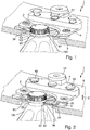
- a device 1 for closing filled containers 100 with a screw cap 2 is shown in a perspective schematic representation in two different states.
- the container 100 is shown in the form of a non-bearing bottle, which has no support ring at its neck portion 102 accordingly. Rather, it is only one not visible in the figures retaining ring 104 is provided, which serves to secure a guarantee strip 20 of the screw cap 2.
- the securing ring 104 is correspondingly structured on its outer side in such a way that it can interact with an inner structure of the guarantee strip 20.
- the two structures are coordinated so that when closing the container 100 with the screw 2 only a small resistance to the guarantee strip 20 is exercised, so that a non-destructive closing of the container 100 can take place.
- the container 100 is first opened, such a high resistance is exerted on the guarantee strip 20 by the structures that the guarantee strip 20 is either destroyed or torn off.
- the container 100 is held in a neck guide 3 of the device 1, wherein the neck guide 3 has an upwardly directed collar 30 which partially surrounds the neck portion 102 of the container 100 and on whose upper end side a plurality of anti-rotation elements 32 in the form of spikes are provided ,
- the collar 30 and the anti-rotation elements 32 are particularly good in FIG. 2 to recognize, in which the container 100 relative to the in FIG. 1 is raised position shown.
- the anti-rotation elements 32 which are arranged on the upper side of the collar 30 of the neck guide 3, so come into contact with the retaining ring 104 of the container 100 that the container 100 rests with its entire weight on the anti-rotation elements 32. In other words, the container 100 is held exclusively by the anti-rotation elements 32.
- Another edition or holder does not exist in the embodiment shown. In particular, no other support surface is provided on which parts of the container 100 would rest.
- the container 100 Since the entire weight of the filled container 100 rests on the anti-rotation elements 32, the container 100 can be kept particularly against rotation when applying a torque when screwing the screw cap 2. Thus, the closing torque, which is applied to the container 100 via the screw cap 2, which is not shown here, can be reliably supported, so that a rotation of the container 100 during the closing process does not occur or only insignificantly.
- the guarantee strip 20 of a screwed-on screw cap 2 overlaps the anti-rotation elements 32 and at least a part of the collar 30 of the neck guide 3. Accordingly, the guarantee band 20 would be damaged when the container 100 in the in FIG. 1 shown position would be moved laterally out of the neck guide 3 to pass it to a downstream processing station.
- a discharge element 4 which has lifting fingers 40 which engage the screw cap 2 and in the embodiment shown on the guarantee strip 20 and, as can be seen for example FIG. 2 results, the container 100 together with the screwed screw 2 vertical upward from the neck guide 3 and in particular from the collar 30 and the anti-rotation elements 32 can lift out.
- the discharge element 4 is for this purpose movable relative to the neck guide 3 and in particular in the vertical direction 6 upwards against the neck guide 3 can be lifted.
- the lifting fingers 40 of the discharge element 4 are flat and smooth at their respective front portions in which they contact the container 100, the screw cap 2, or the guarantee band 20, respectively, so that there is no structure preventing a lateral discharge. In other words, the container 100 can be moved onto the lifting fingers 40 without damaging the guarantee strip 20 or other structures of the filled and sealed container 100.
- the lifting fingers 40 are added to complementary recesses 34 of the neck guide 3, such that the lifting fingers 40 in the in FIG. 1 shown closing position below the collar 30 and the anti-rotation elements 32 are arranged.
- the lifting fingers 40 are arranged below the guarantee strip 20 in the fully closed state of the container 100 and more preferably not touch the guarantee strip 20.
- the FIG. 1 shown position of the discharge element 4 is the so-called Verschurgiposition in which the container 100, which is seated with its guarantee strip 104 on the anti-rotation elements 32, can be easily provided with the screw 2 without the screw 2 or the guarantee strip 20 to the lifting fingers 40 of Ausschleusimplantations 4 would abut.
- the closure 2 and the guarantee strip 20 with the discharge element 4 is avoided when screwing the screw 2, so that damage to the screw cap 2 and the guarantee strip 20 can be avoided.
- the discharge element 4 is guided in the embodiment shown via guide pins 42, along which the discharge element 4 in the vertical direction Z can be raised or lowered.
- a biasing spring 44 is the discharge element 4 in the Verschetzposition, as they are in FIG. 1 is shown biased to ensure that when screwing the screw cap 2 damage to the screw cap 2 and the guarantee strip 20 is avoided.
- the lifting or the relative movement of the discharge element 4 with respect to the neck guide 3 is achieved via a magnet 46, which applies a corresponding force in the vertical direction Z to the discharge element 4 via a countermagnet arranged in a discharge region above the magnet 46.
- each neck guide 3 is associated with its own discharge element 4, which rotates together with the neck guide 3 on the rotary carousel 5 during the closing process.
- closing heads are provided above the individual container recesses 50 of the rotary carousel 5, which here define the respective closing points, by means of which the respective screw caps 2 are screwed onto the filled containers 100 arranged in the container recesses 50.
- the capping head can also apply a force in the vertical direction to the screw cap 2 and the container 100 so that a reliable application and closure of the screw cap 2 together with the guarantee strip 20 becomes possible.
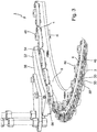
- FIG. 3 further aspects of a device 1 are shown in a further schematic perspective view, in which case again a rotary carousel 5 is provided, on which a plurality of container recesses 50 is provided, which respectively define a plurality of closing points for container 100.
- a neck guide 3 and a discharge element 4 is provided, wherein the neck guide 3 used and the discharge element 4 used are in principle designed as already to the Figures 1 and 2 described.
- the rotary carousel 5 rotates in a direction of rotation R, which is schematically indicated by an arrow.
- a filled and sealed container 100 is in the neck guide 3 as he, for example, in FIG. 1 is shown.
- This filled and sealed container 100 then reaches a discharge area 52 in which it is to be transferred to a subsequent processing station.
- the discharge area 52 is held stationary and the rotary carousel 5 passes below.
- the transport can be achieved here for example via an outlet star.
- a discharge contour 56 is provided, which discharges the resting on the discharge element 4 container 100 at the screw caps 2 gently tangentially.
- a magnet 58 with the same name is provided at the end of the discharge area and after passing through the area of the counter-magnet 54, by means of which the discharge element 4 actively depressed from the Ausschleusposition in the closing position.
- FIG. 4 schematically is a sectional view through the rotary carousel 5 in the area of Ausschleus Symposiumes 52 shown.
- the Ausleuskontur 56 can be seen as well as the region of the counter-magnet 54, by means of which the magnet 46 of the Ausschleusimplantations 4 is attracted to move from the closing position to the Ausschleusposition.
- the discharge element 4 is located in the sectional view corresponding to the raised Ausschleusposition. It is immediately apparent that in this way the surfaces of the Lifting finger 40 are arranged above the collar 30 and the individual anti-rotation elements 32 and according to the container with its container closure and the guarantee strip can slide over these elements away, so that a discharge of the sealed container without destruction of the guarantee strip is possible.
- FIG. 5 is a schematic cross section through the rotary carousel 5 to recognize in a state in which the discharge element 4 is arranged in the lowered closing position.
- the lifting fingers 40 of the discharge element 4 are now arranged below the collar 30 and the individual anti-rotation elements 32, so that an interaction of the discharge element 4 with a screw cap 2 or its guarantee strip 20 is avoided when screwing.
- FIG. 6 is shown in a schematic perspective view again the discharge area 52, which has a corresponding discharge contour 56, at which each lifted by the discharge element 4 containers can be discharged tangentially from the rotary carousel 5.
- each discharge element 4 can also be provided with its own drive, for example a hydraulic or pneumatic lifting cylinder or a servomotor.
- the device 1 described above has been described only in connection with non-bearing containers 100, it is also applicable in connection with a support ring having containers.
- the neck guide 3 and in particular the anti-rotation elements 32 then engage under the support ring.
- the same applies to the discharge element 4, the lifting fingers 40 then also engage under the support ring.
Landscapes
- Engineering & Computer Science (AREA)
- Mechanical Engineering (AREA)
- Sealing Of Jars (AREA)
- Closures For Containers (AREA)
- Filling Of Jars Or Cans And Processes For Cleaning And Sealing Jars (AREA)
Claims (9)
- Dispositif (1) pour fermer un récipient rempli (100) avec un bouchon de fermeture à vis (2), de préférence pour la fermeture de bouteilles sans bague de support avec un bouchon de fermeture à vis, comprenant un guide-goulot (3) avec au moins un élément anti-rotation (32) pour la réception bloquée en rotation d'une section de goulot (102) du récipient rempli (100) lors de la fermeture avec le bouchon de fermeture à vis (2), et un élément d'éjection (4) pour éjecter le récipient fermé (100) du guide-goulot (3), dans lequel le guide-goulot (3) et l'élément d'éjection (4) peuvent être déplacés l'un par rapport à l'autre,
caractérisé en ce que :l'élément d'éjection (4) présente au moins un doigt de levage (40) qui est agencé en position de fermeture en dessous de l'élément anti-rotation (32) et qui est agencé en position d'éjection au moins dans le même niveau que l'élément anti-rotation (32). - Dispositif (1) selon la revendication 1, caractérisé en ce qu'il est prévu au moins deux guides-goulot (3) qui peuvent être déplacés le long d'un trajet de déplacement prédéterminé, de préférence sur un carrousel rotatif (5) et à chaque guide-goulot (3) est affecté un élément d'éjection propre (4).
- Dispositif (1) selon la revendication 1 ou 2, caractérisé en ce que le doigt de levage (40) est agencé en position de fermeture dans un évidement (34) du guide-goulot (3) et forme de préférence avec le guide-goulot (3) une surface sensiblement continue.
- Dispositif (1) selon l'une quelconque des revendications précédentes, caractérisé en ce que l'élément d'éjection (4) et le guide-goulot (3) peuvent être déplacés l'un par rapport à l'autre dans la direction verticale.
- Dispositif (1) selon l'une quelconque des revendications précédentes, caractérisé en ce que le guide-goulot (3) est conçu de sorte qu'il puisse venir en contact avec le récipient (100) seulement dans la zone des éléments anti-rotation (32) et présente de préférence un rebord (30) qui est conformé de manière qu'il entoure au moins en partie la section de goulot (102) du récipient (100) et que, sur sa face avant, les éléments anti-rotation (32) soient prévus pour recevoir un circlip (104) du récipient (100).
- Dispositif (1) selon l'une quelconque des revendications précédentes, caractérisé en ce que l'élément d'éjection (4) et le guide-goulot (3) peuvent être déplacés l'un par rapport à l'autre sans contact et l'élément d'éjection présente de préférence un aimant (46) qui peut, à l'aide d'un contre-aimant (54), déplacer l'élément d'éjection (4) d'une position de fermeture à une position d'éjection.
- Dispositif (1) selon l'une quelconque des revendications précédentes, caractérisé en ce que l'élément d'éjection (4) est précontraint par rapport au guide-goulot (3) dans une position de fermeture dans laquelle le bouchon de fermeture à vis (2) peut être appliqué sur le récipient (100).
- Procédé de fermeture d'un récipient sans bague de support (100) avec un bouchon de fermeture à vis (2), comprenant :la réception du récipient sans bague de support (100) sur au moins un élément anti-rotation (32) d'un guide-goulot (3),la fermeture du récipient sans bague de support (100) au moyen d'un bouchon de fermeture à vis (2) etle déplacement d'un élément d'éjection (4) à amener en prise avec le récipient (100) par rapport au guide-goulot (3) pour soulever le récipient fermé (100) de l'élément anti-rotation (32) du guide-goulot (3),caractérisé en ce que :l'élément d'éjection (4) présente au moins un doigt de levage (40) qui est agencé en position de fermeture en dessous de l'élément anti-rotation (32) et qui est agencé en position d'éjection au moins dans le même niveau que l'élément anti-rotation (32).
- Procédé selon la revendication 8, caractérisé en ce que l'élément anti-rotation (32) descend dans une zone formée par une bande de garantie (20) du bouchon de fermeture à vis (2) et vient en contact avec un circlip (104) du récipient (100).
Applications Claiming Priority (1)
| Application Number | Priority Date | Filing Date | Title |
|---|---|---|---|
| DE102014105907.7A DE102014105907A1 (de) | 2014-04-28 | 2014-04-28 | Vorrichtung und Verfahren zum Verschließen befüllter Behälter mit einem Schraubverschluss |
Publications (2)
| Publication Number | Publication Date |
|---|---|
| EP2939972A1 EP2939972A1 (fr) | 2015-11-04 |
| EP2939972B1 true EP2939972B1 (fr) | 2016-12-21 |
Family
ID=53008359
Family Applications (1)
| Application Number | Title | Priority Date | Filing Date |
|---|---|---|---|
| EP15165297.1A Active EP2939972B1 (fr) | 2014-04-28 | 2015-04-28 | Dispositif et procédé de fermeture de récipients remplis avec un bouchon à fermeture à vis |
Country Status (4)
| Country | Link |
|---|---|
| US (1) | US10399836B2 (fr) |
| EP (1) | EP2939972B1 (fr) |
| CN (1) | CN105016271B (fr) |
| DE (1) | DE102014105907A1 (fr) |
Families Citing this family (7)
| Publication number | Priority date | Publication date | Assignee | Title |
|---|---|---|---|---|
| US10351406B2 (en) * | 2016-01-30 | 2019-07-16 | John M. Leslie | Horizontal/vertical grip anti-rotation capping knife |
| DE102016106378A1 (de) * | 2016-04-07 | 2017-10-12 | Krones Ag | Vorrichtung zum Behandeln von Behältern sowie Getränkeabfüllanlage |
| IT201700047740A1 (it) | 2017-05-03 | 2018-11-03 | Arol Spa | Dispositivo di presa e centraggio di bottiglie per impianti di tappatura |
| DE102018113291B4 (de) * | 2018-06-05 | 2021-07-01 | Krones Ag | Vorrichtung zum Behandeln von Behälterverschlüssen |
| DE102019113653A1 (de) | 2019-05-22 | 2020-11-26 | Krones Ag | Vorrichtung zum Halten eines Behälters und Verschließvorrichtung |
| DE102019130827A1 (de) * | 2019-11-15 | 2021-05-20 | Krones Aktiengesellschaft | Vorrichtung zum Transportieren und Behandeln von Objekten |
| DE102023117271A1 (de) | 2023-06-29 | 2025-01-02 | Krones Aktiengesellschaft | Vorrichtung zum Halten eines Behälters und Verschließvorrichtung |
Family Cites Families (8)
| Publication number | Priority date | Publication date | Assignee | Title |
|---|---|---|---|---|
| US4939890A (en) * | 1989-04-14 | 1990-07-10 | Fci, Inc. | Anti-rotation method and apparatus for bottle capping machines |
| DE4136464A1 (de) * | 1991-11-06 | 1993-05-13 | Seitz Enzinger Noll Masch | Vorrichtung zum vereinzeln und bereitstellen von kronenkorken oder dgl. verschluessen |
| JP4599784B2 (ja) * | 2001-09-25 | 2010-12-15 | 澁谷工業株式会社 | スクリューキャッパ |
| DE102007057284A1 (de) * | 2007-11-28 | 2009-06-04 | Krones Ag | Vorrichtung und Verfahren zum Öffnen oder Verschließen von Behältnissen mittels Schraubverschlüssen |
| IT1399982B1 (it) * | 2010-04-30 | 2013-05-09 | Arol Spa | Dispositivo di presa per macchine tappatrici automatiche |
| US20120017546A1 (en) * | 2010-07-21 | 2012-01-26 | Peronek Michael H | Apparatus and method to prevent bottle rotation |
| DE102012103525A1 (de) * | 2012-04-20 | 2013-10-24 | Krones Ag | Vorrichtung zum Aufnehmen von mit einem Halsring versehenen Flaschen in einem Verschließer |
| DE102012206944A1 (de) * | 2012-04-26 | 2013-10-31 | Krones Ag | Vorrichtung zum Verschließen von Kunststoffflaschen |
-
2014
- 2014-04-28 DE DE102014105907.7A patent/DE102014105907A1/de not_active Withdrawn
-
2015
- 2015-04-24 CN CN201510202595.3A patent/CN105016271B/zh active Active
- 2015-04-28 US US14/698,775 patent/US10399836B2/en active Active
- 2015-04-28 EP EP15165297.1A patent/EP2939972B1/fr active Active
Non-Patent Citations (1)
| Title |
|---|
| None * |
Also Published As
| Publication number | Publication date |
|---|---|
| EP2939972A1 (fr) | 2015-11-04 |
| US10399836B2 (en) | 2019-09-03 |
| CN105016271B (zh) | 2017-06-30 |
| US20150315002A1 (en) | 2015-11-05 |
| CN105016271A (zh) | 2015-11-04 |
| DE102014105907A1 (de) | 2015-10-29 |
Similar Documents
| Publication | Publication Date | Title |
|---|---|---|
| EP2939972B1 (fr) | Dispositif et procédé de fermeture de récipients remplis avec un bouchon à fermeture à vis | |
| EP2684805B1 (fr) | Dispositif pour guider des récipients | |
| EP3753900A1 (fr) | Dispositif de maintien d'un récipient et dispositif de fermeture | |
| WO2008009410A1 (fr) | Machine de traitement pour bouteilles ou récipients similaires | |
| DE2403659A1 (de) | Vorrichtung und verfahren zum entfernen von behaelterverschluessen | |
| DE60108546T2 (de) | Vorrichtung für Maschinen zum Umordnen von Behältern, mit automatischen Mitteln zum Ausrichten und Abwerfen eines empfangenen Behälters | |
| EP3090969B1 (fr) | Dispositif d'amortissement de fermetures de recipients | |
| EP2168880A1 (fr) | Dispositif de déballage de bouteilles à partir d'une unité d'emballage | |
| DE102012103518A1 (de) | Vorrichtung zum Verschließen von Behältern | |
| EP1633663B1 (fr) | Dispositif pour remplir et fermer en continu des emballages en carton/matieres plastiques, ouverts d'un cote, et ensemble cellule servant au transport de tels emballages dans ledit dispositif | |
| DE2212659C3 (de) | Vorrichtung zum Entfernen von Schraubverschlußkapseln von Flaschen u.dgl. Behältern | |
| EP1529750A1 (fr) | Machine pour fermer des récipients ou similaires, avec des fermetures à vis | |
| DE1756881A1 (de) | Vorrichtung zum Greifen und Festhalten von Flaschen,insbesondere Gasflaschen oder aehnlicher Behaelter | |
| DE3626008A1 (de) | Vorrichtung zum verschliessen von flaschen | |
| WO2018162065A1 (fr) | Dispositif et procédé pour le positionnement, le maintien et le guidage de récipients, notamment de type bouteilles | |
| DE10261551B9 (de) | Drehvorrichtung | |
| EP1630125A1 (fr) | Dispositif de bouchage de bouteille ou similaire | |
| DE102012005300A1 (de) | Vorrichtung zum zumindest teilweisen Aufschrauben eines Drehverschlusses auf eine Flasche | |
| DE2726474A1 (de) | Vorrichtung zum entfernen von auf getraenkeflaschen verbliebenen verschlusskapseln | |
| EP3741722B1 (fr) | Agencement de fermeture permettant de fermer un récipient à l'aide d'une fermeture pour récipient | |
| DE19626680A1 (de) | Verschließelement für eine Verschließmaschine | |
| DE4439376C2 (de) | Einrichtung zum Entfernen von Kronenkorken | |
| DE102012110102A1 (de) | Vorrichtung und Verfahren zum Zuführen von Verschlüssen | |
| DE19535872B4 (de) | Einrichtung zum Entfernen von Flaschenverschlüssen von Getränkeflaschen | |
| DE2331690C3 (de) | Schraubverschluß mit Garantieband für Flaschen |
Legal Events
| Date | Code | Title | Description |
|---|---|---|---|
| PUAI | Public reference made under article 153(3) epc to a published international application that has entered the european phase |
Free format text: ORIGINAL CODE: 0009012 |
|
| AK | Designated contracting states |
Kind code of ref document: A1 Designated state(s): AL AT BE BG CH CY CZ DE DK EE ES FI FR GB GR HR HU IE IS IT LI LT LU LV MC MK MT NL NO PL PT RO RS SE SI SK SM TR |
|
| AX | Request for extension of the european patent |
Extension state: BA ME |
|
| 17P | Request for examination filed |
Effective date: 20160321 |
|
| RBV | Designated contracting states (corrected) |
Designated state(s): AL AT BE BG CH CY CZ DE DK EE ES FI FR GB GR HR HU IE IS IT LI LT LU LV MC MK MT NL NO PL PT RO RS SE SI SK SM TR |
|
| GRAP | Despatch of communication of intention to grant a patent |
Free format text: ORIGINAL CODE: EPIDOSNIGR1 |
|
| RIC1 | Information provided on ipc code assigned before grant |
Ipc: B67B 3/20 20060101AFI20160623BHEP |
|
| INTG | Intention to grant announced |
Effective date: 20160708 |
|
| GRAS | Grant fee paid |
Free format text: ORIGINAL CODE: EPIDOSNIGR3 |
|
| STAA | Information on the status of an ep patent application or granted ep patent |
Free format text: STATUS: GRANT OF PATENT IS INTENDED |
|
| GRAA | (expected) grant |
Free format text: ORIGINAL CODE: 0009210 |
|
| STAA | Information on the status of an ep patent application or granted ep patent |
Free format text: STATUS: THE PATENT HAS BEEN GRANTED |
|
| AK | Designated contracting states |
Kind code of ref document: B1 Designated state(s): AL AT BE BG CH CY CZ DE DK EE ES FI FR GB GR HR HU IE IS IT LI LT LU LV MC MK MT NL NO PL PT RO RS SE SI SK SM TR |
|
| REG | Reference to a national code |
Ref country code: GB Ref legal event code: FG4D Free format text: NOT ENGLISH |
|
| REG | Reference to a national code |
Ref country code: CH Ref legal event code: EP |
|
| REG | Reference to a national code |
Ref country code: IE Ref legal event code: FG4D Free format text: LANGUAGE OF EP DOCUMENT: GERMAN |
|
| REG | Reference to a national code |
Ref country code: AT Ref legal event code: REF Ref document number: 855272 Country of ref document: AT Kind code of ref document: T Effective date: 20170115 |
|
| REG | Reference to a national code |
Ref country code: DE Ref legal event code: R096 Ref document number: 502015000412 Country of ref document: DE |
|
| PG25 | Lapsed in a contracting state [announced via postgrant information from national office to epo] |
Ref country code: LV Free format text: LAPSE BECAUSE OF FAILURE TO SUBMIT A TRANSLATION OF THE DESCRIPTION OR TO PAY THE FEE WITHIN THE PRESCRIBED TIME-LIMIT Effective date: 20161221 |
|
| REG | Reference to a national code |
Ref country code: FR Ref legal event code: PLFP Year of fee payment: 3 |
|
| REG | Reference to a national code |
Ref country code: LT Ref legal event code: MG4D |
|
| REG | Reference to a national code |
Ref country code: NL Ref legal event code: MP Effective date: 20161221 |
|
| PG25 | Lapsed in a contracting state [announced via postgrant information from national office to epo] |
Ref country code: LT Free format text: LAPSE BECAUSE OF FAILURE TO SUBMIT A TRANSLATION OF THE DESCRIPTION OR TO PAY THE FEE WITHIN THE PRESCRIBED TIME-LIMIT Effective date: 20161221 Ref country code: SE Free format text: LAPSE BECAUSE OF FAILURE TO SUBMIT A TRANSLATION OF THE DESCRIPTION OR TO PAY THE FEE WITHIN THE PRESCRIBED TIME-LIMIT Effective date: 20161221 Ref country code: NO Free format text: LAPSE BECAUSE OF FAILURE TO SUBMIT A TRANSLATION OF THE DESCRIPTION OR TO PAY THE FEE WITHIN THE PRESCRIBED TIME-LIMIT Effective date: 20170321 Ref country code: GR Free format text: LAPSE BECAUSE OF FAILURE TO SUBMIT A TRANSLATION OF THE DESCRIPTION OR TO PAY THE FEE WITHIN THE PRESCRIBED TIME-LIMIT Effective date: 20170322 |
|
| PG25 | Lapsed in a contracting state [announced via postgrant information from national office to epo] |
Ref country code: RS Free format text: LAPSE BECAUSE OF FAILURE TO SUBMIT A TRANSLATION OF THE DESCRIPTION OR TO PAY THE FEE WITHIN THE PRESCRIBED TIME-LIMIT Effective date: 20161221 Ref country code: HR Free format text: LAPSE BECAUSE OF FAILURE TO SUBMIT A TRANSLATION OF THE DESCRIPTION OR TO PAY THE FEE WITHIN THE PRESCRIBED TIME-LIMIT Effective date: 20161221 Ref country code: FI Free format text: LAPSE BECAUSE OF FAILURE TO SUBMIT A TRANSLATION OF THE DESCRIPTION OR TO PAY THE FEE WITHIN THE PRESCRIBED TIME-LIMIT Effective date: 20161221 |
|
| PG25 | Lapsed in a contracting state [announced via postgrant information from national office to epo] |
Ref country code: NL Free format text: LAPSE BECAUSE OF FAILURE TO SUBMIT A TRANSLATION OF THE DESCRIPTION OR TO PAY THE FEE WITHIN THE PRESCRIBED TIME-LIMIT Effective date: 20161221 |
|
| PG25 | Lapsed in a contracting state [announced via postgrant information from national office to epo] |
Ref country code: EE Free format text: LAPSE BECAUSE OF FAILURE TO SUBMIT A TRANSLATION OF THE DESCRIPTION OR TO PAY THE FEE WITHIN THE PRESCRIBED TIME-LIMIT Effective date: 20161221 Ref country code: SK Free format text: LAPSE BECAUSE OF FAILURE TO SUBMIT A TRANSLATION OF THE DESCRIPTION OR TO PAY THE FEE WITHIN THE PRESCRIBED TIME-LIMIT Effective date: 20161221 Ref country code: IS Free format text: LAPSE BECAUSE OF FAILURE TO SUBMIT A TRANSLATION OF THE DESCRIPTION OR TO PAY THE FEE WITHIN THE PRESCRIBED TIME-LIMIT Effective date: 20170421 Ref country code: CZ Free format text: LAPSE BECAUSE OF FAILURE TO SUBMIT A TRANSLATION OF THE DESCRIPTION OR TO PAY THE FEE WITHIN THE PRESCRIBED TIME-LIMIT Effective date: 20161221 Ref country code: RO Free format text: LAPSE BECAUSE OF FAILURE TO SUBMIT A TRANSLATION OF THE DESCRIPTION OR TO PAY THE FEE WITHIN THE PRESCRIBED TIME-LIMIT Effective date: 20161221 |
|
| PG25 | Lapsed in a contracting state [announced via postgrant information from national office to epo] |
Ref country code: PT Free format text: LAPSE BECAUSE OF FAILURE TO SUBMIT A TRANSLATION OF THE DESCRIPTION OR TO PAY THE FEE WITHIN THE PRESCRIBED TIME-LIMIT Effective date: 20170421 Ref country code: BG Free format text: LAPSE BECAUSE OF FAILURE TO SUBMIT A TRANSLATION OF THE DESCRIPTION OR TO PAY THE FEE WITHIN THE PRESCRIBED TIME-LIMIT Effective date: 20170321 Ref country code: PL Free format text: LAPSE BECAUSE OF FAILURE TO SUBMIT A TRANSLATION OF THE DESCRIPTION OR TO PAY THE FEE WITHIN THE PRESCRIBED TIME-LIMIT Effective date: 20161221 Ref country code: ES Free format text: LAPSE BECAUSE OF FAILURE TO SUBMIT A TRANSLATION OF THE DESCRIPTION OR TO PAY THE FEE WITHIN THE PRESCRIBED TIME-LIMIT Effective date: 20161221 Ref country code: SM Free format text: LAPSE BECAUSE OF FAILURE TO SUBMIT A TRANSLATION OF THE DESCRIPTION OR TO PAY THE FEE WITHIN THE PRESCRIBED TIME-LIMIT Effective date: 20161221 |
|
| REG | Reference to a national code |
Ref country code: DE Ref legal event code: R097 Ref document number: 502015000412 Country of ref document: DE |
|
| PLBE | No opposition filed within time limit |
Free format text: ORIGINAL CODE: 0009261 |
|
| STAA | Information on the status of an ep patent application or granted ep patent |
Free format text: STATUS: NO OPPOSITION FILED WITHIN TIME LIMIT |
|
| 26N | No opposition filed |
Effective date: 20170922 |
|
| PG25 | Lapsed in a contracting state [announced via postgrant information from national office to epo] |
Ref country code: DK Free format text: LAPSE BECAUSE OF FAILURE TO SUBMIT A TRANSLATION OF THE DESCRIPTION OR TO PAY THE FEE WITHIN THE PRESCRIBED TIME-LIMIT Effective date: 20161221 |
|
| REG | Reference to a national code |
Ref country code: IE Ref legal event code: MM4A |
|
| PG25 | Lapsed in a contracting state [announced via postgrant information from national office to epo] |
Ref country code: MC Free format text: LAPSE BECAUSE OF FAILURE TO SUBMIT A TRANSLATION OF THE DESCRIPTION OR TO PAY THE FEE WITHIN THE PRESCRIBED TIME-LIMIT Effective date: 20161221 |
|
| PG25 | Lapsed in a contracting state [announced via postgrant information from national office to epo] |
Ref country code: SI Free format text: LAPSE BECAUSE OF FAILURE TO SUBMIT A TRANSLATION OF THE DESCRIPTION OR TO PAY THE FEE WITHIN THE PRESCRIBED TIME-LIMIT Effective date: 20161221 Ref country code: LU Free format text: LAPSE BECAUSE OF NON-PAYMENT OF DUE FEES Effective date: 20170428 |
|
| REG | Reference to a national code |
Ref country code: FR Ref legal event code: PLFP Year of fee payment: 4 |
|
| REG | Reference to a national code |
Ref country code: BE Ref legal event code: MM Effective date: 20170430 |
|
| PG25 | Lapsed in a contracting state [announced via postgrant information from national office to epo] |
Ref country code: IE Free format text: LAPSE BECAUSE OF NON-PAYMENT OF DUE FEES Effective date: 20170428 |
|
| PG25 | Lapsed in a contracting state [announced via postgrant information from national office to epo] |
Ref country code: BE Free format text: LAPSE BECAUSE OF NON-PAYMENT OF DUE FEES Effective date: 20170430 |
|
| PG25 | Lapsed in a contracting state [announced via postgrant information from national office to epo] |
Ref country code: MT Free format text: LAPSE BECAUSE OF FAILURE TO SUBMIT A TRANSLATION OF THE DESCRIPTION OR TO PAY THE FEE WITHIN THE PRESCRIBED TIME-LIMIT Effective date: 20161221 |
|
| REG | Reference to a national code |
Ref country code: CH Ref legal event code: PL |
|
| PG25 | Lapsed in a contracting state [announced via postgrant information from national office to epo] |
Ref country code: CH Free format text: LAPSE BECAUSE OF NON-PAYMENT OF DUE FEES Effective date: 20180430 Ref country code: LI Free format text: LAPSE BECAUSE OF NON-PAYMENT OF DUE FEES Effective date: 20180430 |
|
| PG25 | Lapsed in a contracting state [announced via postgrant information from national office to epo] |
Ref country code: HU Free format text: LAPSE BECAUSE OF FAILURE TO SUBMIT A TRANSLATION OF THE DESCRIPTION OR TO PAY THE FEE WITHIN THE PRESCRIBED TIME-LIMIT; INVALID AB INITIO Effective date: 20150428 |
|
| PG25 | Lapsed in a contracting state [announced via postgrant information from national office to epo] |
Ref country code: CY Free format text: LAPSE BECAUSE OF FAILURE TO SUBMIT A TRANSLATION OF THE DESCRIPTION OR TO PAY THE FEE WITHIN THE PRESCRIBED TIME-LIMIT Effective date: 20161221 |
|
| PG25 | Lapsed in a contracting state [announced via postgrant information from national office to epo] |
Ref country code: MK Free format text: LAPSE BECAUSE OF FAILURE TO SUBMIT A TRANSLATION OF THE DESCRIPTION OR TO PAY THE FEE WITHIN THE PRESCRIBED TIME-LIMIT Effective date: 20161221 |
|
| GBPC | Gb: european patent ceased through non-payment of renewal fee |
Effective date: 20190428 |
|
| PG25 | Lapsed in a contracting state [announced via postgrant information from national office to epo] |
Ref country code: GB Free format text: LAPSE BECAUSE OF NON-PAYMENT OF DUE FEES Effective date: 20190428 |
|
| PG25 | Lapsed in a contracting state [announced via postgrant information from national office to epo] |
Ref country code: TR Free format text: LAPSE BECAUSE OF FAILURE TO SUBMIT A TRANSLATION OF THE DESCRIPTION OR TO PAY THE FEE WITHIN THE PRESCRIBED TIME-LIMIT Effective date: 20161221 |
|
| PG25 | Lapsed in a contracting state [announced via postgrant information from national office to epo] |
Ref country code: AL Free format text: LAPSE BECAUSE OF FAILURE TO SUBMIT A TRANSLATION OF THE DESCRIPTION OR TO PAY THE FEE WITHIN THE PRESCRIBED TIME-LIMIT Effective date: 20161221 |
|
| REG | Reference to a national code |
Ref country code: AT Ref legal event code: MM01 Ref document number: 855272 Country of ref document: AT Kind code of ref document: T Effective date: 20200428 |
|
| PG25 | Lapsed in a contracting state [announced via postgrant information from national office to epo] |
Ref country code: AT Free format text: LAPSE BECAUSE OF NON-PAYMENT OF DUE FEES Effective date: 20200428 |
|
| P01 | Opt-out of the competence of the unified patent court (upc) registered |
Effective date: 20230523 |
|
| REG | Reference to a national code |
Ref country code: DE Ref legal event code: R082 Ref document number: 502015000412 Country of ref document: DE Representative=s name: MAUCHER JENKINS PATENTANWAELTE & RECHTSANWAELT, DE |
|
| PGFP | Annual fee paid to national office [announced via postgrant information from national office to epo] |
Ref country code: DE Payment date: 20250305 Year of fee payment: 11 |
|
| PGFP | Annual fee paid to national office [announced via postgrant information from national office to epo] |
Ref country code: IT Payment date: 20260320 Year of fee payment: 12 |
|
| PGFP | Annual fee paid to national office [announced via postgrant information from national office to epo] |
Ref country code: FR Payment date: 20260309 Year of fee payment: 12 |