EP2940213A1 - Arbre de commande à oscillations découplées pour un appareil de travail - Google Patents
Arbre de commande à oscillations découplées pour un appareil de travail Download PDFInfo
- Publication number
- EP2940213A1 EP2940213A1 EP15001086.6A EP15001086A EP2940213A1 EP 2940213 A1 EP2940213 A1 EP 2940213A1 EP 15001086 A EP15001086 A EP 15001086A EP 2940213 A1 EP2940213 A1 EP 2940213A1
- Authority
- EP
- European Patent Office
- Prior art keywords
- drawbar
- section
- hand
- handle
- longitudinal
- Prior art date
- Legal status (The legal status is an assumption and is not a legal conclusion. Google has not performed a legal analysis and makes no representation as to the accuracy of the status listed.)
- Granted
Links
Images


Classifications
-
- E—FIXED CONSTRUCTIONS
- E01—CONSTRUCTION OF ROADS, RAILWAYS, OR BRIDGES
- E01C—CONSTRUCTION OF, OR SURFACES FOR, ROADS, SPORTS GROUNDS, OR THE LIKE; MACHINES OR AUXILIARY TOOLS FOR CONSTRUCTION OR REPAIR
- E01C19/00—Machines, tools or auxiliary devices for preparing or distributing paving materials, for working the placed materials, or for forming, consolidating, or finishing the paving
- E01C19/22—Machines, tools or auxiliary devices for preparing or distributing paving materials, for working the placed materials, or for forming, consolidating, or finishing the paving for consolidating or finishing laid-down unset materials
- E01C19/30—Tamping or vibrating apparatus other than rollers ; Devices for ramming individual paving elements
- E01C19/34—Power-driven rammers or tampers, e.g. air-hammer impacted shoes for ramming stone-sett paving; Hand-actuated ramming or tamping machines, e.g. tampers with manually hoisted dropping weight
- E01C19/35—Hand-held or hand-guided tools
-
- A—HUMAN NECESSITIES
- A01—AGRICULTURE; FORESTRY; ANIMAL HUSBANDRY; HUNTING; TRAPPING; FISHING
- A01D—HARVESTING; MOWING
- A01D34/00—Mowers; Mowing apparatus of harvesters
- A01D34/01—Mowers; Mowing apparatus of harvesters characterised by features relating to the type of cutting apparatus
- A01D34/412—Mowers; Mowing apparatus of harvesters characterised by features relating to the type of cutting apparatus having rotating cutters
- A01D34/63—Mowers; Mowing apparatus of harvesters characterised by features relating to the type of cutting apparatus having rotating cutters having cutters rotating about a vertical axis
- A01D34/82—Other details
- A01D34/824—Handle arrangements
Definitions
- the invention relates according to claim 1, a hand-held implement with a drawbar with handle device.
- the implement may be configured, for example, as a working device for soil compaction or agricultural implement, for example as a vibrating plate, compaction roller or mower.
- vibrations of the implement may burden the hands or arms of the leading operator.
- Additional hand-arm vibration calls for additional measures, such as limiting and documenting the operator's working hours.
- the invention has for its object to provide a hand-held implement, on the one hand has improved ergonomics and usability and on the other hand improved operator protection.
- a hand-held implement has a working device and a tiller device coupled to the working device for guiding the working device.
- the drawbar device has a drawbar section coupled to the work device by a vibration uncoupling device and a handle device arranged on the drawbar section with a first handle region and a second grip region.
- the first grip region and the second grip region are arranged such that a twisting axis of the drawbar section relative to the working device, which is caused by the design of the vibration isolation device, runs essentially centrally between the first grip region and the second grip region.
- the hand-held implement may be any pedestrian-controlled implement, the operation, such as pulling, pushing, steering and controlling a locomotion and / or a working movement of the implement by a Operator by means of or with the help of the drawbar device allows.
- it may be a working device in which during the operation of strong vibrations occur that could be initiated via the drawbar device in the hands or arms of the operator.
- the hand-held implement may be, for example, a drawbar-guided vibrating plate, a drawbar-guided compaction roller or a tiller-guided, agricultural tillage or mower.
- the working device may include a tooling device such as a soil contact plate for soil compaction, a roller device or a mower deck. Furthermore, it may have a drive device such as an electric and / or fuel engine, which can generate a working movement of the tool device and / or a locomotion of the implement.
- the drive can set a ground contact plate having and elastically coupled to an upper mass lower mass of the working device relative to the upper mass in vibration and thus generate both the working movement of the ground contact plate and the locomotion of the implement. This can cause strong vibrations, so that the drive can be considered as a vibration exciter.
- the working device on a drawbar device.
- This may comprise a drawbar section coupled to the working device by a vibration decoupling device.
- the tiller portion may be elongate, which may result in a substantially elongated tiller structure which allows either pulling or pushing the implement on the tiller device.
- the vibration decoupling device can bring about a possible oscillation decoupling coupling of the drawbar section to the working device.
- the drawbar section can be decoupled from the vibrations of the working device.
- the vibrations and vibrations generated at the working device can consequently be damped by the vibration decoupling device and the hands and arms of the operator can be protected.
- the vibration decoupling device may include elastic connecting elements, such as rubber bumpers, disposed between the working device and the drawbar section. Alternatively or additionally, further vibration decoupling elements such as spring-damper devices provided and arranged between working device and drawbar section.
- the vibration decoupling device By the vibration decoupling device, an elastic connection between the working device and drawbar section is achieved, on the one hand basis for the vibration decoupling and on the other hand allows a certain play and thus twisting of the drawbar section relative to the working device.
- a twisting axis of possible twisting between the working device and the drawbar section may result, which may extend, for example, approximately along the drawbar device or to the drawbar section.
- the gripping device arranged on the drawbar section has the first and second gripping areas in each case for applying a first or second hand of the operator, thus allowing the operator a comfortable and effective two-handed gripping and thus operating or guiding the working device.
- the first and second gripping regions are arranged such that the twisting axis of the vibration decoupling device extends substantially centrally between the first and second gripping regions and thus centrally between the two hands of the leading operator.
- the first and second handle device can be arranged in the same distance from the operator's perspective left or right of the twisting axis and left and right of an imaginary extension of the twisting axis in the direction of the operator.
- an imaginary linear connecting line of the respective middle points of attack of the gripping areas, at which the centers of the respective palm of the operator comes to rest in normal operation can pass through the twisting axis and be divided by these into two sections of substantially equal length.
- the drawbar device may include a lower drawbar part which may be coupled to the work device.
- a lower drawbar part which may be coupled to the work device.
- Such a compound can be designed largely vibration resistant. It may be substantially rigid or alternatively movable, for example by means of a hinge or hinge connection.
- the drawbar section can be arranged above the vibration uncoupling device.
- the drawbar section has a first longitudinal section arranged on the vibration uncoupling device and a second longitudinal section arranged on an end of the first longitudinal section opposite the vibration uncoupling device, wherein the handle device is arranged on the second longitudinal section.
- These longitudinal sections can be rigidly connected to each other.
- the two-part embodiment of the drawbar section allows various structural configurations and forms of arrangement of the first and second handle portion laterally adjacent to the twisting axis.
- the second longitudinal section may extend at an angle relative to the first longitudinal section, in particular angled downwards relative to a use position of the drawbar device.
- an angle between a central axis of the first longitudinal section and a central axis of the second longitudinal section may be less than or equal to 170 °, for example also less than 150 °.
- the angled arrangement of the second longitudinal section makes it possible to arrange the handle device in the manner of a guide bracket above the downwardly angled second longitudinal section, so that it is easily accessible to the operator.
- the handle device as a guide bracket coupled to the second longitudinal section lower cross member and two from the operator's perspective left and right on the lower cross member scheduled, have substantially upwardly extending longitudinal beams, wherein the longitudinal beams have the grip areas.
- the gripping device may have an additional, for example, the longitudinal bars above connecting upper cross member and thus designed as a closed bracket. On the lateral side rails, the user can create his hands like a steering wheel.
- the vibration decoupling device reduces the initiation of hand-arm vibrations.
- the second longitudinal section may extend axially offset relative to the first longitudinal section and / or an axial offset of the second longitudinal section relative to the first longitudinal section may substantially offset the first grip area and / or the second grip area relative to an arrangement area of the grip device, in which the gripping device is coupled to the second longitudinal section compensate.
- the second longitudinal section can be offset axially downwards, the gripping device can extend upwards from the arrangement area.
- the axial offset between the first and second longitudinal sections can be achieved, for example, by an offset component that is rigidly connected to the first and second longitudinal sections, for example.
- the grip device for example in the form of the above-described guide bracket
- the second longitudinal section in such a way that it is ensured that the grip areas are arranged laterally next to the twisting axis.
- the longitudinal bars of the guide bracket can be arranged laterally next to the twisting axis.
- the vibration decoupling device can be designed and / or arranged such that the twisting axis does not run parallel to a longitudinal axis of the drawbar section.
- the twisting axis can run obliquely to the longitudinal axis of the drawbar section and, for example, rise 15 ° or 30 ° steeper than the longitudinal axis of the drawbar section towards the operator.
- Such an arrangement makes it possible to arrange the gripping device on the drawbar section, for example, in the manner of an upwardly directed guide bar and to ensure that both the first and the second gripping area come to lie laterally next to the obliquely arranged twisting axis relative to the longitudinal axis of the drawbar section. Consequently, a good steerability is ensured with a simple design and effective vibration damping.
- the vibration decoupling device may comprise at least two vibration decoupling elements.
- the vibration decoupling elements may be disposed at different points along the twist axis.
- the arrangement of the vibration decoupling elements, the course of the torsion axis can be influenced or fixed. If the vibration decoupling elements are arranged obliquely to the longitudinal axis of the drawbar section, then - depending on the type of vibration decoupling elements - also the twisting axis can also run obliquely to the longitudinal axis of the drawbar section.
- the spacing of the vibration decoupling elements arranged along the longitudinal axis of the drawbar section or the twisting axis may be in a range of 20% to 40% of the effective drawbar length.
- the effective drawbar length is understood to be the length between the connection of the drawbar device to the working device and the connection of the handle device to the drawbar device.
- the vibration decoupling elements may include rubber buffers or spring-damper elements.
- the lower drawbar part and the drawbar section may be arranged with a matching longitudinal axis, wherein the twisting axis extends obliquely thereto.
- the design of the vibration decoupling device with obliquely to the longitudinal axis of the drawbar device or obliquely to the longitudinal axis of the drawbar section extending Verwindungsachse allows a simple and inexpensive vibration damping while ensuring good steering, since the lever arm is avoided in the initiation of steering movements.
- the gripping device may be designed as a handle bar which rises upwards, for example, which is arranged, for example, rotatably on the drawbar section. Alternatively or additionally, by rotating the handle device, a speed and / or a direction of movement of the working device can be selected.
- a direction of rotation of the gripping device can be defined substantially perpendicular to the longitudinal axis of the drawbar device and / or perpendicular to the twisting axis.
- the operator can control the direction of travel and / or speed of the implement, for example by moving the handle bar forward or backward with different deflection.
- the implement in the state, so essentially work on the spot.
- the lever When the lever is moved forward, the implement also moves forward.
- the lever When the lever is moved backwards, the implement moves backwards.
- the travel speed can be adjusted.
- the lateral turning or pressing the handle bar by the operator can be designed as a steering movement in the embodiments described above and effectively transmitted to the working device via the tiller device.
- the working device may e.g. to be twisted about its vertical axis.
- the embodiments mentioned enable a vibration decoupling of the drawbar while effectively guiding or steerability of the working device, since a shortened lever arm between the axis of rotation of the drawbar and the point of application the operator is reached or a lever arm between a central axis of the steering movement and the twisting axis is completely avoided. Good controllability of the implement can be guaranteed.
- the operator is spared because vibrations of the working device are introduced only damped in the drawbar device, in particular the handle device. This benefits both the employer, for whom the obligation to document working hours, and the worker who is only exposed to slight hand-arm vibrations and who nevertheless can accurately guide the implement.
- Fig. 1 schematically shows in a side view serving as Bodenverdichtungsvorraum vibration plate 1, which has an upper mass 2 with drive motor arranged therein and a lower mass spring-coupled to the lower mass with a ground contact plate 3.
- These elements of the vibrating plate 1 form a working device.
- the working device can be guided and controlled via a drawbar device.
- the tiller device is connected via a drawbar 4, for example, substantially vibration-resistant with the upper mass 2 of the working device. It has an attached to the drawbar 4 or with this movably connected lower drawbar part 5 and connected to the lower drawbar part 5 upper drawbar part 6.
- a guide bracket serving handle 7 arranged at the upper drawbar part 6 .
- the handle bracket 7 extends from its coupling on the upper drawbar part 6 upwards and can be pivotable or rotatable about an axis of rotation 8.
- the drawbar device designed in this way allows the operator to operate the vibrating plate 1 and to control both its working movement and its movement on the handle 7. For example, the operator can control the direction of travel and / or the pitching movement of the implement by moving / swiveling the handlebar 7 forward or backward with different deflection.
- the structure and operation of such unbalance exciter vibration plates is known, so that at this point a more detailed description is unnecessary.
- the unbalance exciter generates a resulting, oscillating force, with the one hand, a compaction effect and on the other hand a propulsion (forward and reverse travel) of the vibrating plate 1 can be generated.
- the vibrating plate 1 or the unbalance exciter in the state so essentially work on the spot.
- the vibrating plate 1 also starts moving in this direction.
- the travel speed can be adjusted.
- control options is merely an example.
- Other control options such as a control of the direction of movement via a separate lever, knob, slide or switch while rigid arrangement of the guide bracket 7 on the upper drawbar part 6 are also possible.
- a vibration decoupling device 9 is provided between the lower drawbar part 5 and the upper drawbar part 6, for example, two or more vibration decoupling elements 9a in the form of rubber buffers and / or spring damper Elements.
- a torsion axis 10 is created, which may extend, for example, in the longitudinal direction of at least one of the drawbar parts 5, 6.
- the upper drawbar part 6 can thus rotate about the twisting axis 10 relative to the lower drawbar part 5 held rigidly on the vibration plate 1 with respect to the twisting axis 10.
- the upper drawbar part 6 has a design with two rigidly coupled longitudinal sections 11 and 12 adjoining one another at the end face.
- the upper, second longitudinal section 12 is designed as an inclined tiller head. It extends angled and in particular inclined downwards.
- the handle bar 7 can be arranged such that the twisting axis 10 or its imaginary extension in the direction of the attacking the handle 7 operator centrally between a first handle portion 7a and a second handle portion 7b of the handle bracket 7 and thus runs centrally between the attacking hands of the operator ,
- the first grip area 7a can be held by, for example, the left hand of the operator, while the right hand of the operator grasps the second grip area 7b.
- the operator can initiate a steering movement into the drawbar device, which allows steering of the movement of the vibration plate 1.
- a long lever arm between the starting point of the operator on the handle bar 7, namely the grip areas 7a, 7b, and the twisting axis 10 is avoided, which could lead to strong torsions along the axis and thereby make the leadership of the vibrating plate 1 indirectly and "spongy" , Consequently, the steering movement of the operator can be transmitted to the vibration plate 1 effectively and directly via the tiller device.
- the construction of the drawbar device shown makes it possible, by means of the vibration uncoupling device 9, on the one hand, to decouple the handlebar 7 from harmful vibrations of the vibration plate 1. On the other hand, intuitive steering movement the operator on the handle bar 7 are effectively transferred to the vibrating plate 1, so that it is intuitively steerable and exactly feasible.
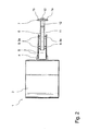
- Fig. 2 shows the embodiment Fig. 1 in a plan view in which the structural design of the tiller device in particular is clear. From the vibration plate 1, the upper mass 2 is shown, at which the drawbar 4 with recording of the lower drawbar part 5 is connected. Between two side parts of the lower drawbar part 5, the upper drawbar part 6 is arranged and coupled to the lower drawbar part 5 via a plurality of vibration decoupling elements 9a, for example rubber buffers, the vibration decoupling device.
- vibration decoupling elements 9a for example rubber buffers
- the upper drawbar part 6 is formed in two parts with a lower longitudinal section 11 and a rigidly connected to the lower longitudinal section 11 upper longitudinal section 12, wherein the upper longitudinal section 12 is designed as an inclined tiller head.
- the upper longitudinal section 12 is designed as an inclined tiller head.
- On the inclined tiller head 12 of the handle bar 7 is arranged such that between the side grip portions 7a, 7b of the handle bracket 7 centrally the twisting axis 10 extends. This allows intuitive steering while effectively limiting hand-arm vibration.
- the upper drawbar part 6 has an axial offset between the first longitudinal section 11 and the second longitudinal section 12, on which the handle bar 7 is arranged.
- the axial offset is achieved in this embodiment by an offset component 13, which is in each case rigidly connected to the first and second longitudinal sections 11, 12.
- the axial offset ensures that the grip areas 7a, 7b of the grip bracket 7 are arranged laterally next to the twisting axis 10, so that an intuitive steering movement with simultaneously effective vibration decoupling can be achieved.
- the vibrating plate 1 is therefore on the one hand exactly feasible and spares the other hand, the hands and arms of the operator from harmful vibrations.
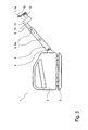
- the vibration decoupling elements 9a of the vibration decoupling device 9 are such arranged between the lower drawbar part 5 and the upper drawbar part 6, that resulting from the degrees of freedom of movement between the lower and upper drawbar part 5, 6 resulting relative torsion axis 10 is not parallel to a longitudinal axis of the lower and / or upper drawbar part 5, 6.
- the lower drawbar part 5 and the upper drawbar part 6 have - as shown in the figures - an elongated extension, which define their longitudinal axis.
- the twisting axis 10 extends obliquely to the longitudinal axes of the lower and upper drawbar part 5, 6, as in FIG Fig. 4 good to see.
- the spacing of the vibration decoupling elements 9a arranged along the longitudinal axis of the drawbar parts 5, 6 or the twisting axis 10 may be in a range of 20% to 40% of the effective drawbar length.
- the effective drawbar length is the length between the attachment of the drawbar device to the working device (here for example the connection of the lower drawbar part 5 to the drawbar stand 4) and the connection of the handle bar 7 to the drawbar device (here: to the upper drawbar part 6).
- the illustrated embodiments of the drawbar-guided vibration plate 1 can be analogously transferred to other pedestrian-controlled implements. They enable and support an intuitive steering behavior with exact guidance and controllability of the implement, while at the same time protecting the operator's hands and arms against damaging vibrations.
Landscapes
- Engineering & Computer Science (AREA)
- Architecture (AREA)
- Civil Engineering (AREA)
- Structural Engineering (AREA)
- Life Sciences & Earth Sciences (AREA)
- Environmental Sciences (AREA)
- Harvester Elements (AREA)
Applications Claiming Priority (1)
| Application Number | Priority Date | Filing Date | Title |
|---|---|---|---|
| DE102014006256.2A DE102014006256A1 (de) | 2014-04-28 | 2014-04-28 | Schwingungsentkoppelte Lenkdeichsel für ein Arbeitsgerät |
Publications (2)
| Publication Number | Publication Date |
|---|---|
| EP2940213A1 true EP2940213A1 (fr) | 2015-11-04 |
| EP2940213B1 EP2940213B1 (fr) | 2018-10-10 |
Family
ID=53039154
Family Applications (1)
| Application Number | Title | Priority Date | Filing Date |
|---|---|---|---|
| EP15001086.6A Active EP2940213B1 (fr) | 2014-04-28 | 2015-04-15 | Arbre de commande à oscillations découplées pour un outil de travail |
Country Status (2)
| Country | Link |
|---|---|
| EP (1) | EP2940213B1 (fr) |
| DE (1) | DE102014006256A1 (fr) |
Cited By (2)
| Publication number | Priority date | Publication date | Assignee | Title |
|---|---|---|---|---|
| US12065790B2 (en) | 2020-07-07 | 2024-08-20 | Milwaukee Electric Tool Corporation | Plate compactor |
| US12312752B2 (en) | 2020-07-07 | 2025-05-27 | Milwaukee Electric Tool Corporation | Plate compactor |
Citations (2)
| Publication number | Priority date | Publication date | Assignee | Title |
|---|---|---|---|---|
| DE69916413T2 (de) * | 1999-02-03 | 2004-08-12 | Metso Dynapac Ab | Vibrationsplatte mit einem einstellbaren vibrationsgedämpften Handgriff |
| DE102006059774A1 (de) * | 2006-12-15 | 2008-06-26 | Ammann Verdichtung Gmbh | Bodenverdichtungsgerät |
Family Cites Families (6)
| Publication number | Priority date | Publication date | Assignee | Title |
|---|---|---|---|---|
| DE8423337U1 (de) * | 1984-08-06 | 1984-11-15 | Weber Maschinentechnik Gmbh, 5928 Laasphe | Vibrationsplatte mit elastisch gehaltenem griff |
| DE9319973U1 (de) * | 1993-12-24 | 1994-03-03 | Wacker-Werke Gmbh & Co Kg, 85084 Reichertshofen | Schwingungsgedämpfter Handgriff |
| DE10007869C1 (de) * | 2000-02-21 | 2001-08-23 | Ammann Verdichtung Gmbh | Vibrationsplatte |
| DE102004015588A1 (de) * | 2004-03-01 | 2005-09-22 | Bomag Gmbh | Arbeitsgerät mit schwingungsgedämpftem Führungselement |
| DE202009004301U1 (de) * | 2008-03-27 | 2009-11-19 | Wacker Neuson Se | Bodenverdichtungsvorrichtung mit schwingungsisolierter Deichsel |
| JP2013170393A (ja) * | 2012-02-21 | 2013-09-02 | Hitachi Construction Machinery Camino Co Ltd | 振動プレート |
-
2014
- 2014-04-28 DE DE102014006256.2A patent/DE102014006256A1/de not_active Withdrawn
-
2015
- 2015-04-15 EP EP15001086.6A patent/EP2940213B1/fr active Active
Patent Citations (2)
| Publication number | Priority date | Publication date | Assignee | Title |
|---|---|---|---|---|
| DE69916413T2 (de) * | 1999-02-03 | 2004-08-12 | Metso Dynapac Ab | Vibrationsplatte mit einem einstellbaren vibrationsgedämpften Handgriff |
| DE102006059774A1 (de) * | 2006-12-15 | 2008-06-26 | Ammann Verdichtung Gmbh | Bodenverdichtungsgerät |
Cited By (3)
| Publication number | Priority date | Publication date | Assignee | Title |
|---|---|---|---|---|
| US12065790B2 (en) | 2020-07-07 | 2024-08-20 | Milwaukee Electric Tool Corporation | Plate compactor |
| US12234613B2 (en) | 2020-07-07 | 2025-02-25 | Milwaukee Electric Tool Corporation | Plate compactor |
| US12312752B2 (en) | 2020-07-07 | 2025-05-27 | Milwaukee Electric Tool Corporation | Plate compactor |
Also Published As
| Publication number | Publication date |
|---|---|
| EP2940213B1 (fr) | 2018-10-10 |
| DE102014006256A1 (de) | 2015-10-29 |
Similar Documents
| Publication | Publication Date | Title |
|---|---|---|
| EP2216141B1 (fr) | Machine-outil portable avec poignée anti-vibration | |
| EP1404493A1 (fr) | Machine-outil portative presentant une poignee avec un systeme d'amortissement des vibrations | |
| DE19919385A1 (de) | Motorgetriebenes Arbeitsgerät | |
| DE102007000093A1 (de) | Handwerkzeuggerät | |
| DE102008062603A1 (de) | Arbeitsgerät | |
| DE3447401A1 (de) | Hammer mit schutzhaube | |
| DE10132951B4 (de) | Handgeführtes Arbeitsgerät | |
| EP2357283B1 (fr) | Dispositif de guidage à oscillations réduites | |
| EP3749806B1 (fr) | Tirefonneuse-boulonneuse à percussion pour serrer et desserrer des écrous et des boulons d'une voie ferrée | |
| DE202009000264U1 (de) | Dämpfungselement | |
| EP1817139B1 (fr) | Systeme de prehension de machine-outil portative pourvu d'une unite antivibrations | |
| EP2940213B1 (fr) | Arbre de commande à oscillations découplées pour un outil de travail | |
| DE69808662T2 (de) | Tragbare landwirtschaftliche maschine mit schwingungsdämpfung und schutz für den bediener | |
| DE4007919C2 (fr) | ||
| DE3629811C2 (fr) | ||
| EP0662371B1 (fr) | Poignée à amortissement des vibrations | |
| EP1672165B1 (fr) | Appareil pour travaux de construction | |
| DE102010026575B4 (de) | Handwerkzeugmaschine, insbesondere eine Heckenschere | |
| EP3787389B1 (fr) | Dispositif porte-équipement pour un véhicule et véhicule | |
| DE102005062883A1 (de) | Schwingungsreduktion bei Elektrowerkzeugen | |
| DE102015202103A1 (de) | Fahrzeug, insbesondere Kettenfahrzeug zur Schneepistengestaltung und -pflege | |
| DE202004000783U1 (de) | Vorrichtung zum Schieben eines Trennschleiferwagens | |
| DE102004015588A1 (de) | Arbeitsgerät mit schwingungsgedämpftem Führungselement | |
| EP1571259A1 (fr) | Machine avec dispositif de guidage amorti contre les vibrations | |
| DE102004048681A1 (de) | Aufbruchhammer mit Mehrfachgreifsystem |
Legal Events
| Date | Code | Title | Description |
|---|---|---|---|
| PUAI | Public reference made under article 153(3) epc to a published international application that has entered the european phase |
Free format text: ORIGINAL CODE: 0009012 |
|
| AK | Designated contracting states |
Kind code of ref document: A1 Designated state(s): AL AT BE BG CH CY CZ DE DK EE ES FI FR GB GR HR HU IE IS IT LI LT LU LV MC MK MT NL NO PL PT RO RS SE SI SK SM TR |
|
| AX | Request for extension of the european patent |
Extension state: BA ME |
|
| TPAC | Observations filed by third parties |
Free format text: ORIGINAL CODE: EPIDOSNTIPA |
|
| TPAC | Observations filed by third parties |
Free format text: ORIGINAL CODE: EPIDOSNTIPA |
|
| 17P | Request for examination filed |
Effective date: 20160429 |
|
| RBV | Designated contracting states (corrected) |
Designated state(s): AL AT BE BG CH CY CZ DE DK EE ES FI FR GB GR HR HU IE IS IT LI LT LU LV MC MK MT NL NO PL PT RO RS SE SI SK SM TR |
|
| TPAC | Observations filed by third parties |
Free format text: ORIGINAL CODE: EPIDOSNTIPA |
|
| STAA | Information on the status of an ep patent application or granted ep patent |
Free format text: STATUS: EXAMINATION IS IN PROGRESS |
|
| 17Q | First examination report despatched |
Effective date: 20170208 |
|
| GRAP | Despatch of communication of intention to grant a patent |
Free format text: ORIGINAL CODE: EPIDOSNIGR1 |
|
| STAA | Information on the status of an ep patent application or granted ep patent |
Free format text: STATUS: GRANT OF PATENT IS INTENDED |
|
| INTG | Intention to grant announced |
Effective date: 20180509 |
|
| GRAS | Grant fee paid |
Free format text: ORIGINAL CODE: EPIDOSNIGR3 |
|
| GRAA | (expected) grant |
Free format text: ORIGINAL CODE: 0009210 |
|
| STAA | Information on the status of an ep patent application or granted ep patent |
Free format text: STATUS: THE PATENT HAS BEEN GRANTED |
|
| AK | Designated contracting states |
Kind code of ref document: B1 Designated state(s): AL AT BE BG CH CY CZ DE DK EE ES FI FR GB GR HR HU IE IS IT LI LT LU LV MC MK MT NL NO PL PT RO RS SE SI SK SM TR |
|
| REG | Reference to a national code |
Ref country code: GB Ref legal event code: FG4D Free format text: NOT ENGLISH |
|
| REG | Reference to a national code |
Ref country code: CH Ref legal event code: EP Ref country code: AT Ref legal event code: REF Ref document number: 1051399 Country of ref document: AT Kind code of ref document: T Effective date: 20181015 |
|
| REG | Reference to a national code |
Ref country code: IE Ref legal event code: FG4D Free format text: LANGUAGE OF EP DOCUMENT: GERMAN |
|
| REG | Reference to a national code |
Ref country code: DE Ref legal event code: R096 Ref document number: 502015006287 Country of ref document: DE |
|
| REG | Reference to a national code |
Ref country code: SE Ref legal event code: TRGR |
|
| REG | Reference to a national code |
Ref country code: NL Ref legal event code: MP Effective date: 20181010 |
|
| REG | Reference to a national code |
Ref country code: LT Ref legal event code: MG4D |
|
| PG25 | Lapsed in a contracting state [announced via postgrant information from national office to epo] |
Ref country code: NL Free format text: LAPSE BECAUSE OF FAILURE TO SUBMIT A TRANSLATION OF THE DESCRIPTION OR TO PAY THE FEE WITHIN THE PRESCRIBED TIME-LIMIT Effective date: 20181010 |
|
| PG25 | Lapsed in a contracting state [announced via postgrant information from national office to epo] |
Ref country code: BG Free format text: LAPSE BECAUSE OF FAILURE TO SUBMIT A TRANSLATION OF THE DESCRIPTION OR TO PAY THE FEE WITHIN THE PRESCRIBED TIME-LIMIT Effective date: 20190110 Ref country code: ES Free format text: LAPSE BECAUSE OF FAILURE TO SUBMIT A TRANSLATION OF THE DESCRIPTION OR TO PAY THE FEE WITHIN THE PRESCRIBED TIME-LIMIT Effective date: 20181010 Ref country code: LT Free format text: LAPSE BECAUSE OF FAILURE TO SUBMIT A TRANSLATION OF THE DESCRIPTION OR TO PAY THE FEE WITHIN THE PRESCRIBED TIME-LIMIT Effective date: 20181010 Ref country code: NO Free format text: LAPSE BECAUSE OF FAILURE TO SUBMIT A TRANSLATION OF THE DESCRIPTION OR TO PAY THE FEE WITHIN THE PRESCRIBED TIME-LIMIT Effective date: 20190110 Ref country code: IS Free format text: LAPSE BECAUSE OF FAILURE TO SUBMIT A TRANSLATION OF THE DESCRIPTION OR TO PAY THE FEE WITHIN THE PRESCRIBED TIME-LIMIT Effective date: 20190210 Ref country code: LV Free format text: LAPSE BECAUSE OF FAILURE TO SUBMIT A TRANSLATION OF THE DESCRIPTION OR TO PAY THE FEE WITHIN THE PRESCRIBED TIME-LIMIT Effective date: 20181010 Ref country code: HR Free format text: LAPSE BECAUSE OF FAILURE TO SUBMIT A TRANSLATION OF THE DESCRIPTION OR TO PAY THE FEE WITHIN THE PRESCRIBED TIME-LIMIT Effective date: 20181010 Ref country code: PL Free format text: LAPSE BECAUSE OF FAILURE TO SUBMIT A TRANSLATION OF THE DESCRIPTION OR TO PAY THE FEE WITHIN THE PRESCRIBED TIME-LIMIT Effective date: 20181010 Ref country code: FI Free format text: LAPSE BECAUSE OF FAILURE TO SUBMIT A TRANSLATION OF THE DESCRIPTION OR TO PAY THE FEE WITHIN THE PRESCRIBED TIME-LIMIT Effective date: 20181010 |
|
| PG25 | Lapsed in a contracting state [announced via postgrant information from national office to epo] |
Ref country code: AL Free format text: LAPSE BECAUSE OF FAILURE TO SUBMIT A TRANSLATION OF THE DESCRIPTION OR TO PAY THE FEE WITHIN THE PRESCRIBED TIME-LIMIT Effective date: 20181010 Ref country code: GR Free format text: LAPSE BECAUSE OF FAILURE TO SUBMIT A TRANSLATION OF THE DESCRIPTION OR TO PAY THE FEE WITHIN THE PRESCRIBED TIME-LIMIT Effective date: 20190111 Ref country code: RS Free format text: LAPSE BECAUSE OF FAILURE TO SUBMIT A TRANSLATION OF THE DESCRIPTION OR TO PAY THE FEE WITHIN THE PRESCRIBED TIME-LIMIT Effective date: 20181010 Ref country code: PT Free format text: LAPSE BECAUSE OF FAILURE TO SUBMIT A TRANSLATION OF THE DESCRIPTION OR TO PAY THE FEE WITHIN THE PRESCRIBED TIME-LIMIT Effective date: 20190210 |
|
| REG | Reference to a national code |
Ref country code: DE Ref legal event code: R097 Ref document number: 502015006287 Country of ref document: DE |
|
| PG25 | Lapsed in a contracting state [announced via postgrant information from national office to epo] |
Ref country code: CZ Free format text: LAPSE BECAUSE OF FAILURE TO SUBMIT A TRANSLATION OF THE DESCRIPTION OR TO PAY THE FEE WITHIN THE PRESCRIBED TIME-LIMIT Effective date: 20181010 Ref country code: IT Free format text: LAPSE BECAUSE OF FAILURE TO SUBMIT A TRANSLATION OF THE DESCRIPTION OR TO PAY THE FEE WITHIN THE PRESCRIBED TIME-LIMIT Effective date: 20181010 Ref country code: DK Free format text: LAPSE BECAUSE OF FAILURE TO SUBMIT A TRANSLATION OF THE DESCRIPTION OR TO PAY THE FEE WITHIN THE PRESCRIBED TIME-LIMIT Effective date: 20181010 |
|
| PLBE | No opposition filed within time limit |
Free format text: ORIGINAL CODE: 0009261 |
|
| STAA | Information on the status of an ep patent application or granted ep patent |
Free format text: STATUS: NO OPPOSITION FILED WITHIN TIME LIMIT |
|
| PG25 | Lapsed in a contracting state [announced via postgrant information from national office to epo] |
Ref country code: SM Free format text: LAPSE BECAUSE OF FAILURE TO SUBMIT A TRANSLATION OF THE DESCRIPTION OR TO PAY THE FEE WITHIN THE PRESCRIBED TIME-LIMIT Effective date: 20181010 Ref country code: EE Free format text: LAPSE BECAUSE OF FAILURE TO SUBMIT A TRANSLATION OF THE DESCRIPTION OR TO PAY THE FEE WITHIN THE PRESCRIBED TIME-LIMIT Effective date: 20181010 Ref country code: RO Free format text: LAPSE BECAUSE OF FAILURE TO SUBMIT A TRANSLATION OF THE DESCRIPTION OR TO PAY THE FEE WITHIN THE PRESCRIBED TIME-LIMIT Effective date: 20181010 Ref country code: SK Free format text: LAPSE BECAUSE OF FAILURE TO SUBMIT A TRANSLATION OF THE DESCRIPTION OR TO PAY THE FEE WITHIN THE PRESCRIBED TIME-LIMIT Effective date: 20181010 |
|
| 26N | No opposition filed |
Effective date: 20190711 |
|
| PGFP | Annual fee paid to national office [announced via postgrant information from national office to epo] |
Ref country code: CH Payment date: 20190424 Year of fee payment: 5 |
|
| PG25 | Lapsed in a contracting state [announced via postgrant information from national office to epo] |
Ref country code: SI Free format text: LAPSE BECAUSE OF FAILURE TO SUBMIT A TRANSLATION OF THE DESCRIPTION OR TO PAY THE FEE WITHIN THE PRESCRIBED TIME-LIMIT Effective date: 20181010 |
|
| REG | Reference to a national code |
Ref country code: BE Ref legal event code: MM Effective date: 20190430 |
|
| PG25 | Lapsed in a contracting state [announced via postgrant information from national office to epo] |
Ref country code: MC Free format text: LAPSE BECAUSE OF FAILURE TO SUBMIT A TRANSLATION OF THE DESCRIPTION OR TO PAY THE FEE WITHIN THE PRESCRIBED TIME-LIMIT Effective date: 20181010 Ref country code: LU Free format text: LAPSE BECAUSE OF NON-PAYMENT OF DUE FEES Effective date: 20190415 |
|
| PG25 | Lapsed in a contracting state [announced via postgrant information from national office to epo] |
Ref country code: BE Free format text: LAPSE BECAUSE OF NON-PAYMENT OF DUE FEES Effective date: 20190430 |
|
| PG25 | Lapsed in a contracting state [announced via postgrant information from national office to epo] |
Ref country code: TR Free format text: LAPSE BECAUSE OF FAILURE TO SUBMIT A TRANSLATION OF THE DESCRIPTION OR TO PAY THE FEE WITHIN THE PRESCRIBED TIME-LIMIT Effective date: 20181010 |
|
| PG25 | Lapsed in a contracting state [announced via postgrant information from national office to epo] |
Ref country code: IE Free format text: LAPSE BECAUSE OF NON-PAYMENT OF DUE FEES Effective date: 20190415 |
|
| PGFP | Annual fee paid to national office [announced via postgrant information from national office to epo] |
Ref country code: FR Payment date: 20200421 Year of fee payment: 6 |
|
| PGFP | Annual fee paid to national office [announced via postgrant information from national office to epo] |
Ref country code: GB Payment date: 20200423 Year of fee payment: 6 Ref country code: SE Payment date: 20200423 Year of fee payment: 6 |
|
| REG | Reference to a national code |
Ref country code: CH Ref legal event code: PL |
|
| PG25 | Lapsed in a contracting state [announced via postgrant information from national office to epo] |
Ref country code: CH Free format text: LAPSE BECAUSE OF NON-PAYMENT OF DUE FEES Effective date: 20200430 Ref country code: LI Free format text: LAPSE BECAUSE OF NON-PAYMENT OF DUE FEES Effective date: 20200430 |
|
| PG25 | Lapsed in a contracting state [announced via postgrant information from national office to epo] |
Ref country code: CY Free format text: LAPSE BECAUSE OF FAILURE TO SUBMIT A TRANSLATION OF THE DESCRIPTION OR TO PAY THE FEE WITHIN THE PRESCRIBED TIME-LIMIT Effective date: 20181010 |
|
| REG | Reference to a national code |
Ref country code: AT Ref legal event code: MM01 Ref document number: 1051399 Country of ref document: AT Kind code of ref document: T Effective date: 20200415 |
|
| PG25 | Lapsed in a contracting state [announced via postgrant information from national office to epo] |
Ref country code: HU Free format text: LAPSE BECAUSE OF FAILURE TO SUBMIT A TRANSLATION OF THE DESCRIPTION OR TO PAY THE FEE WITHIN THE PRESCRIBED TIME-LIMIT; INVALID AB INITIO Effective date: 20150415 Ref country code: MT Free format text: LAPSE BECAUSE OF FAILURE TO SUBMIT A TRANSLATION OF THE DESCRIPTION OR TO PAY THE FEE WITHIN THE PRESCRIBED TIME-LIMIT Effective date: 20181010 |
|
| PG25 | Lapsed in a contracting state [announced via postgrant information from national office to epo] |
Ref country code: AT Free format text: LAPSE BECAUSE OF NON-PAYMENT OF DUE FEES Effective date: 20200415 |
|
| REG | Reference to a national code |
Ref country code: SE Ref legal event code: EUG |
|
| GBPC | Gb: european patent ceased through non-payment of renewal fee |
Effective date: 20210415 |
|
| PG25 | Lapsed in a contracting state [announced via postgrant information from national office to epo] |
Ref country code: GB Free format text: LAPSE BECAUSE OF NON-PAYMENT OF DUE FEES Effective date: 20210415 Ref country code: FR Free format text: LAPSE BECAUSE OF NON-PAYMENT OF DUE FEES Effective date: 20210430 Ref country code: SE Free format text: LAPSE BECAUSE OF NON-PAYMENT OF DUE FEES Effective date: 20210416 |
|
| PG25 | Lapsed in a contracting state [announced via postgrant information from national office to epo] |
Ref country code: MK Free format text: LAPSE BECAUSE OF FAILURE TO SUBMIT A TRANSLATION OF THE DESCRIPTION OR TO PAY THE FEE WITHIN THE PRESCRIBED TIME-LIMIT Effective date: 20181010 |
|
| PGFP | Annual fee paid to national office [announced via postgrant information from national office to epo] |
Ref country code: DE Payment date: 20250417 Year of fee payment: 11 |