EP2940231B1 - Bracket for an access platform - Google Patents
Bracket for an access platform Download PDFInfo
- Publication number
- EP2940231B1 EP2940231B1 EP15165144.5A EP15165144A EP2940231B1 EP 2940231 B1 EP2940231 B1 EP 2940231B1 EP 15165144 A EP15165144 A EP 15165144A EP 2940231 B1 EP2940231 B1 EP 2940231B1
- Authority
- EP
- European Patent Office
- Prior art keywords
- main body
- plates
- main
- recess
- base member
- Prior art date
- Legal status (The legal status is an assumption and is not a legal conclusion. Google has not performed a legal analysis and makes no representation as to the accuracy of the status listed.)
- Active
Links
Images


Classifications
-
- E—FIXED CONSTRUCTIONS
- E04—BUILDING
- E04G—SCAFFOLDING; FORMS; SHUTTERING; BUILDING IMPLEMENTS OR AIDS, OR THEIR USE; HANDLING BUILDING MATERIALS ON THE SITE; REPAIRING, BREAKING-UP OR OTHER WORK ON EXISTING BUILDINGS
- E04G7/00—Connections between parts of the scaffold
- E04G7/02—Connections between parts of the scaffold with separate coupling elements
- E04G7/06—Stiff scaffolding clamps for connecting scaffold members of common shape
- E04G7/12—Clamps or clips for crossing members
- E04G7/14—Clamps or clips for crossing members for clamping the members independently
-
- E—FIXED CONSTRUCTIONS
- E04—BUILDING
- E04G—SCAFFOLDING; FORMS; SHUTTERING; BUILDING IMPLEMENTS OR AIDS, OR THEIR USE; HANDLING BUILDING MATERIALS ON THE SITE; REPAIRING, BREAKING-UP OR OTHER WORK ON EXISTING BUILDINGS
- E04G3/00—Scaffolds essentially supported by building constructions, e.g. adjustable in height
- E04G3/28—Mobile scaffolds; Scaffolds with mobile platforms
- E04G3/30—Mobile scaffolds; Scaffolds with mobile platforms suspended by flexible supporting elements, e.g. cables
Definitions
- the present invention relates to a bracket for an access platform and in particular but not exclusively for a modular access platform.
- the present invention further relates to an access platform and in particular but not exclusively a modular access platform comprising at least one bracket.
- Double couplers are widely used to connect two orthogonally extending tubular members to each other.
- a double coupler comprises first and second clamps which are each configured to clamp around a different one of two tubular members with the apertures defined by the first and second clamps when closed being oriented orthogonally to each other.
- a double coupler is therefore operative as a bracket to support one tubular member on another tubular member.
- Joining a main tubular member which extends along the length of an access platform to first and second tubular members which extend in opposite directions across the width of the access platform therefore involves using a first double coupler to connect the main tubular member to the first tubular member and a second double coupler to connect the main tubular member to the second tubular member with the first and second double couplers being clamped at locations which are spaced apart from each other by a small distance along the main tubular member.
- Each of EP 1 544 478 , FR 2 944 073 and DE 806 050 C discloses a bracket for an access platform comprising a main body defining a channel configured to receive and provide a close fit around an elongate member of an access platform.
- the present invention has been devised in the light of the inventors' appreciation of shortcomings of the prior art. It is therefore an object for the present invention to provide an improved bracket for a modular access platform. It is a further object for the present invention to provide a modular access platform comprising at least one improved bracket.
- a bracket for an access platform according to claim 1. Particular embodiments are set out in the dependent claims.
- the bracket is brought into use by, for example, receiving an elongate member, such as a scaffolding tube, in the channel defined by the main body.
- the channel is configured such that it is a close fit around the elongate member.
- First and second connection arrangements are mechanically coupled to the main body and extend from oppositely directed sides of the main body.
- a first further elongate member, such as further scaffolding tube is mechanically coupled to the first connection arrangement and a second further elongate member is mechanically coupled to the second connection arrangement such that the first and second further elongate members extend from oppositely directed sides of the main body.
- the bracket may be configured such that the first and second further elongate members extend away from the elongate member received in the channel of the main body.
- the bracket may thus be operative to support the first and second further elongate members from the elongate member received in the channel of the main body.
- only one bracket according to the invention is required to couple three elongate members to each other.
- Brackets according to the invention may be used in this fashion to form an access platform.
- the bracket is therefore configured to form part of an access platform and more specifically a suspended access platform.
- the bracket may be for a temporary access platform.
- Temporary suspended access platforms are often used where installation or maintenance operations are being carried out at a location where it is impracticable to provide ground supported access platforms.
- the access platform may be modular to thereby provide for ease of configuration of the access platform for the application to hand and perhaps also for ease of installation of the access platform before work commences and of removal of the access platform when work is complete.
- the bracket is configured such that the first and second connection arrangements are aligned with each other.
- the first and second connection arrangements therefore extend from corresponding locations on oppositely directed sides of the main body.
- proximal ends of elongate members that are mechanically coupled to the first and second connection arrangements may be in registration with each other.
- the bracket may be configured such that, in use, longitudinal axes of the first and second further elongate members are aligned.
- the bracket may be configured such that, in use, at least one of the first and second further elongate members may extend orthogonally of an elongate member received in the channel of the main body. More specifically both of the first and second further elongate members may extend orthogonally of an elongate member received in the channel of the main body. Therefore the first further elongate member may be orthogonal to the elongate member received in the channel and the second further elongate member may be orthogonal to the elongate member received in the channel.
- the channel defined by the main body is an open channel. More specifically the channel is open at a side opposite a base of the channel. The channel is open at each end of the channel. When an elongate member is received in the channel the channel may therefore straddle the elongate member.
- the channel may be of substantially rectangular cross-section. The channel may be configured to receive and provide a close fit around a standard scaffolding tube such as tube of 48.3 mm outer diameter.
- the main body comprises first and second main plates which are spaced apart from each other.
- the first and second main plates are of substantially the same shape.
- An edge of each of the first and second main plates are joined to each other by a base member.
- the first and second main plates may define opposing surfaces which are substantially parallel to each other.
- the base member and the first and second main plates may thus define the channel.
- the base member and the first and second main plates may be integrally formed. More specifically the base member and the first and second main plates may be formed by shaping a sheet of metal.
- the main body may be formed from steel, such as structural steel and more specifically S700 grade steel.
- the main body may be configured, such as in respect of at least one of its shape, dimensions and material, such that distal ends of the first and second main plates flex. Flexing of the first and second main plates may provide for a tight fit of the channel around the elongate member received in the channel.
- Each of the first and second main plates may be configured such that an edge of the main plate which extends beyond the base member and which is oriented towards the channel defining surface of the base member may be spaced apart from the channel defining surface of the base member in a depth-wise direction of the channel.
- a part of each of the first and second main plates which joins to the base member may therefore be higher than a part of the main plate which extends beyond the base member. Configuring the main plates in this fashion may save on material used to form the main plates.
- the first apertures may be disposed towards a first end of the main plates and the second apertures may be disposed towards a second, opposite end of the main plates.
- the first and second apertures may be disposed towards a distal edge of the main plates and the main plates may be of sufficient height that the base member and the apertures are on opposite sides of an elongate member such as a standard scaffolding tube.
- the bracket may further comprise first and second securing arrangements, such as a nut and bolt arrangement.
- the first securing arrangement may mechanically couple with the first apertures in the first and second main plates such that, for example, an elongate member in the channel is held between the base member and the first securing arrangement.
- the second securing arrangement may mechanically couple with the second apertures in the first and second main plates such that, for example, an elongate member in the channel is held between the base member and the second securing arrangement.
- the base member may define a base aperture.
- the base aperture may be located generally and more specifically substantially centrally in the base member.
- the base aperture may in cooperation with a securing arrangement, such as a nut and bolt arrangement, provide for attachment of a decking component to the base member. Decking may thus be attached to a frame comprising at least one bracket to thereby form a surface from which work may be done.
- Each of the first and second connection arrangements defines a recess for receiving a further elongate member.
- the recess is defined in part by opposing surfaces of a connection arrangement. The opposing surfaces may be sides of the recess.
- the recess is further defined by an exterior surface of the main body from which the connection arrangement extends. The exterior surface may be a base of the recess.
- a connection arrangement comprises first and second spaced apart connector plates.
- the first and second connector plates are spaced apart by a distance sufficient to admit an elongate member, such as a standard scaffolding tube, therebetween.
- the first and second connector plates are of substantially a same shape.
- the first and second connector plates are aligned with each other.
- Each of the first and second connector plates may have the form of lugs which abut at one end against the main body and extend from the main body.
- a connector arrangement is configured to mechanically couple to a further elongate member, such as a standard scaffolding tube.
- the connector arrangement comprises first and second connector plates
- each of the first and second connector plates may define a first connector aperture with the first connector apertures being in registration with each other.
- the first connector apertures may be operative in cooperation with a securing arrangement, such as a nut and bolt arrangement, to secure the connector arrangement to an elongate member such as by way of an aperture formed in the elongate member which is in registration with the first connector apertures.
- a securing arrangement such as a nut and bolt arrangement
- Each of the first and second connector plates may define a second connector aperture spaced apart from the first connector aperture either towards or away from the main body, with the second connector apertures being in registration with each other.
- the second connector apertures may be operative in cooperation with a securing arrangement to attach the elongate member to the connector arrangement more securely.
- an aperture may be formed towards an end of an elongate member at a location and the elongate member may be attached to the first and second connector plates by way of the aperture formed in elongate member such that the elongate member is pivotable in relation to the bracket about an axis defined by the aperture formed in the elongate member.
- the elongate member may be secured against pivoting in relation to the bracket by way of a second aperture which is formed in the elongate member at a location spaced along the elongate member from the first aperture and which cooperates with the second pair of apertures formed in the first and second connector plates.
- a main body recess is defined by opposing edges of the first and second lugs and an edge of the bridge element.
- the main body recess receives the main body. More specifically the main body comprises a base member, the main body recess defining edge of the bridge element abuts against the base member.
- the main body recess defining edge of the bridge element may abut against the surface of the base member oriented away from the channel defined by the main body.
- Each of the first and the second integrally formed arrangements and the main body may comprise inter-engaging profiles which cooperate to restrict movement of the integrally formed arrangement relative to the main body in at least one of: the direction of the channel; and a direction orthogonal to the channel and a depth-wise direction of the channel.
- the integrally formed arrangement may comprise a protrusion, for example on the bridge element, and the main body may comprise a recess, for example in the base member, the protrusion being configured to be received at least in part in the recess.
- a frame for an access platform comprising at least one bracket according to the first aspect of the present invention and at least three elongate members which are coupled to each other by way of the at least one bracket.
- an access platform according to claim 11, which comprises a bracket as defined in the previous claims.
- the access platform may be a suspended access platform.
- the access platform may be a modular access platform.
- Embodiments of the second aspect of the present invention may comprise one or more features of the first aspect of the present invention.
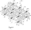
- a frame 10 for an access platform is shown in Figure 1 .
- the frame 10 for the access platform is of a form that is suspended by suspension brackets (not shown) which are mechanically coupled at spaced apart locations to the frame 10.
- the frame 10 comprises five planar frames. Two of the planar frames 12 are spaced apart from each other and extend lengthwise along the frame 10. The remaining three planar frames 14 extend width-wise between the two lengthwise extending planar frames 12. One of the width-wise extending planar frames 14 is located towards one end of the frame 10. A second width-wise extending planar frame 14 is located towards the opposite end of the frame 10. The third width-wise extending planar frame 14 is located half way along the frame 10.
- the access platform further comprises decking components (not shown) which are attached, as described further below, to the top of the frame 10 shown in Figure 1 to form a planar surface from which work can be done.
- Each of the five planar frames 12, 14 comprises two spaced apart and horizontally extending tubes 16 (which constitute elongate members) and plural vertically extending tubes 18 (which constitute elongate members) which extend between the horizontally extending tubes 16.
- Each of the five planar frames 12, 14 further comprises cross braces 20 which extend diagonally between horizontally and vertically extending tubes to thereby increase the rigidity of the planar frame.
- the horizontally and vertically extending tubes 16, 18 are of standard scaffolding form. In the present embodiment the horizontally and vertically extending tubes 16, 18 have an outer diameter of 48.3 mm and are formed of either aluminium or stainless steel.
- the horizontally and vertically extending tubes 16, 18 and the cross braces 20 of each planar frame 12, 14 are connected rigidly to each other by welding.
- Each width-wise extending planar frame 14 is connected at each of two ends to a lengthwise extending planar frame 12 by a pair of first and second brackets 22, 24.
- the first and second brackets 22, 24 are of the same form and function.
- the first bracket 22 in a pair connects the upper horizontally extending tube 16 of the width-wise extending planar frame 14 to the upper horizontally extending tube 16 of the lengthwise extending planar frame 12 and the second bracket 24 in a pair connects the lower horizontally extending tube 16 of the width-wise extending planar frame 14 to the lower horizontally extending tube 16 of the lengthwise extending planar frame 12.
- each bracket 22, 24 is configured to connect to a horizontally extending tube of a further width-wise extending planar frame (not shown) further to the horizontally extending tube of the width-wise extending planar frame 14 shown in Figure 1 .
- a wider frame than the frame 10 shown in Figure 1 may thus be formed wherein horizontally extending tubes of two different width-wise extending planar frames are connected to and extend from opposite sides of a bracket 22, 24.
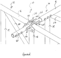
- FIG. 2 A partial view of the frame 10 of Figure 1 is shown in Figure 2 .
- the partial view shows one bracket 22 in detail.
- Components of Figure 2 in common with Figure 1 are designated with like reference numerals. The reader's attention is therefore directed to Figure 1 for a description of such common components.
- the bracket 22 comprises a main body 42 which defines a channel that is configured to receive and provide a close fit around the upper horizontally extending tube 16 of the lengthwise extending planar frame 12.
- the main body 42 comprises a nut 44 which is attached to the top of the main body 42.
- the nut 44 along with nuts of other brackets provide for securing of decking components to the top of the frame 10.
- the main body 42 is described further below with reference to Figures 3A to 3D .
- First and second connection arrangements 46, 48 extend from oppositely directed sides of the main body 42 in directions orthogonal to the channel defined by the main body 42 and hence orthogonal to the upper horizontally extending tube 16 of the lengthwise extending planar frame 12.
- the first and second connection arrangements 46, 48 are described further below with reference to Figures 3A to 3D .
- First and second tubular struts 50, 52 of moderate length are fastened at one end by way of two nut and bolt arrangements to a respective one of the first and second connection arrangements 46, 48.
- Figures 3A to 3D respectively provide a perspective view, a plan view, a view from one end and a view from one side of the bracket of Figure 2 .
- Components of Figures 3A to 3D in common with Figure 2 are designated with like reference numerals.
- the bracket 22 comprises a main body 42, a first connection arrangement 46 and a second connection arrangement 48.
- the first and second connection arrangements 46, 48 extend from corresponding locations on oppositely directed sides of the main body 42 in directions orthogonal to the channel defined by the main body 42.
- the channel 62 defined by the main body 42 is open at a side opposite a base of the channel and open at each end of the channel.
- the channel 62 is of substantially rectangular cross-section.
- the width of the channel is 48.9 mm whereby the channel is configured to receive and provide a close fit around a standard scaffolding tube of 48.3 mm outer diameter.
- Figures 4A to 4D respectively provide a perspective view, a plan view, a view from one end and a view from one side of the perspective view of the main body of the bracket shown in Figures 3A to 3D .
- the main body 42 comprises a base member 64, a first main plate 66 and a second main plate 68.
- the first and second main plates 66, 68 are of substantially the same shape and spaced apart from each other to define the channel 62 therebetween.
- An edge of each of the first and second main plates 66, 68 are joined to each other by the base member 64 whereby the base member defines the base of the channel 62.
- the first and second main plates 66, 68 extend further along the direction of the channel 62 than the base member 64 by a same amount of 44.35 mm at each of two oppositely directed ends of the base member.
- an edge of the main plate drops away from the base member whereby the part of the main plate that extends beyond the base member is narrower than the part of the main plate that is joined to the base member.
- the opposing, i.e. bottom, edge of the main plate is straight between near the distal ends of the main plate.
- the distal ends of the main plate are rounded.
- Each of the first and second main plates 66, 68 is 148.7 mm long and 84 mm high at the part of the main plate that is joined to the base member 64.
- the parts of the main plate that extend beyond the base member 64 are each 45.7 mm high.
- Each of the first and second main plates 66, 68 define first and second apertures 70, 72 which are spaced apart from each other along the direction of the channel 62 by 100 mm.
- the first apertures 70 are therefore disposed towards a first end of the main plates and the second apertures 72 are disposed towards a second, opposite end of the main plates.
- the first apertures 70 of the first and second main plates 66, 68 are in registration with each other and the second apertures 72 of the first and second main plates 66, 68 are in registration with each other.
- a spacing of 100 mm between the first and second apertures 70, 72 allows the bracket 22 to be secured to a tube in a frame such that the channel spans a vertically extending tube and perhaps also bracing members which extend from the horizontally extending tube and such that the bracket can be secured to the tube on opposite sides of the vertically extending tube and perhaps also bracing members.
- the bracket 22 As described above, as one progresses along each of the first and second main plates 66, 68 in either direction away from the base member 64, an edge of the main plate drops away from the base member.
- a centre of each of the first and second apertures 70, 72 is therefore spaced apart from the plane defined by the base member 64 by 61.15 mm whereby the base member and the apertures 70, 72 are on opposite sides of a standard scaffolding tube having an outer diameter of 48.3 mm when the scaffolding tube is received in the channel 62.
- the main body is attached to the tube by way of nut and bolt arrangements which are received in the first and second apertures 70, 72 of the first and second main plates 66, 68.
- connection arrangement 46, 48 The sides of the recess are defined by opposing surfaces of a connection arrangement 46, 48 with the base of the recess being defined by an exterior surface of the main body 42 from which the connection arrangement extends.
- the first and second connection arrangements 46, 48 are constituted by first and second spaced connector plates 82 (which each constitute an integrally formed arrangement) which are mounted on the main body 42 such that they are spaced apart from each other.
- the first and second connector plates 82 are of substantially a same shape and align with each other when mounted on the main body 42.
- Each of the first and second connector plates 82 is formed from S700 grade steel. Each of the first and second connector plates 82 is configured when mounted on the main body to extend from oppositely directed sides of the main body 42 whereby both connector plates 82 constitute the first and second connection arrangements 46, 48. Each of the first and second connector plates 82 comprises first and second lugs 84, 86 which are spaced apart from each other and joined by a bridge element 88 with the first and second lugs and the bridge element all lying in the same plane.
- a main body recess 90 is defined by opposing edges of the first and second lugs 84, 86 and an edge of the bridge element 88. The main body recess 90 is configured to receive the main body 42 such that the main body recess defining edge of the bridge element 88 abuts against the base member 64.
- an end of a scaffolding tube or an end of one of the tubular struts 50, 52 shown in Figure 2 which has two apertures of a size and spacing corresponding to the first and second connector apertures 96, 98, is received between opposing lugs of the first and second connector plates 82.
- the two apertures in the scaffolding tube or tubular strut are provided at locations such that the end of the tube or strut abuts against the side of the main body to thereby prevent rotation of the scaffolding tube or tubular strut about the bolt in relation to the main body.
- a second nut and bolt arrangement is then received in the other of the two apertures in the scaffolding tube or tubular strut and in a pair of the other of the first and second connector apertures 96, 98 to thereby attach the scaffolding tube or tubular strut to the bracket 22 more securely.
- the two apertures in the scaffolding tube or tubular strut are provided at locations such that the end of the tube or strut is spaced apart from the side of the main body to thereby allow rotation of the scaffolding tube or tubular strut about the first bolt in relation to the main body.
- a frame 10 may be installed by assembling a frame sub-assembly in an upright position before lowering the assembled frame sub-assembly by rotation about the first bolts which couple plural scaffolding tubes or tubular struts to respective brackets.
- first bolts which couple plural scaffolding tubes or tubular struts to respective brackets.
- second nut and bolt arrangements are then each received in the other of the two apertures in a scaffolding tube or tubular strut and in a pair of the other of first and second connector apertures 96, 98 of a respective bracket to thereby secure against rotation about the first bolts.
Landscapes
- Engineering & Computer Science (AREA)
- Architecture (AREA)
- Mechanical Engineering (AREA)
- Civil Engineering (AREA)
- Structural Engineering (AREA)
- Mutual Connection Of Rods And Tubes (AREA)
- Bridges Or Land Bridges (AREA)
- Clamps And Clips (AREA)
Priority Applications (1)
| Application Number | Priority Date | Filing Date | Title |
|---|---|---|---|
| PL15165144T PL2940231T3 (pl) | 2014-04-30 | 2015-04-25 | Węzłówka do platformy dostępowej |
Applications Claiming Priority (1)
| Application Number | Priority Date | Filing Date | Title |
|---|---|---|---|
| GBGB1407610.3A GB201407610D0 (en) | 2014-04-30 | 2014-04-30 | Bracket for an access platform |
Publications (2)
| Publication Number | Publication Date |
|---|---|
| EP2940231A1 EP2940231A1 (en) | 2015-11-04 |
| EP2940231B1 true EP2940231B1 (en) | 2020-05-27 |
Family
ID=50972115
Family Applications (1)
| Application Number | Title | Priority Date | Filing Date |
|---|---|---|---|
| EP15165144.5A Active EP2940231B1 (en) | 2014-04-30 | 2015-04-25 | Bracket for an access platform |
Country Status (5)
| Country | Link |
|---|---|
| EP (1) | EP2940231B1 (da) |
| AU (1) | AU2015201846B2 (da) |
| DK (1) | DK2940231T3 (da) |
| GB (1) | GB201407610D0 (da) |
| PL (1) | PL2940231T3 (da) |
Family Cites Families (5)
| Publication number | Priority date | Publication date | Assignee | Title |
|---|---|---|---|---|
| DE806050C (de) * | 1950-03-14 | 1951-06-11 | Martin Messner | Geruestverbinder unter Zuhilfenahme von Rohrschellen |
| ES2203270B1 (es) * | 2001-02-14 | 2005-02-16 | Ingenieria De Encofrados Y Servicios, S.L. | Perfeccionamientos en andamios de fachada. |
| FR2864181B1 (fr) * | 2003-12-18 | 2006-10-20 | Husson Collectivites Sa | Collier d'assemblage |
| JP5013263B2 (ja) * | 2007-10-26 | 2012-08-29 | 株式会社ダイフク | 棒状部材に対する部材取付け構造 |
| FR2944073B1 (fr) * | 2009-04-06 | 2011-07-22 | Antonio Viola | Noeud mecanique permettant de maintenir par serrement trois poutres de section rectangulaire |
-
2014
- 2014-04-30 GB GBGB1407610.3A patent/GB201407610D0/en not_active Ceased
-
2015
- 2015-04-13 AU AU2015201846A patent/AU2015201846B2/en active Active
- 2015-04-25 EP EP15165144.5A patent/EP2940231B1/en active Active
- 2015-04-25 PL PL15165144T patent/PL2940231T3/pl unknown
- 2015-04-25 DK DK15165144.5T patent/DK2940231T3/da active
Non-Patent Citations (1)
| Title |
|---|
| None * |
Also Published As
| Publication number | Publication date |
|---|---|
| AU2015201846B2 (en) | 2019-03-28 |
| DK2940231T3 (da) | 2020-08-31 |
| GB201407610D0 (en) | 2014-06-11 |
| EP2940231A1 (en) | 2015-11-04 |
| AU2015201846A1 (en) | 2015-11-19 |
| PL2940231T3 (pl) | 2020-11-30 |
Similar Documents
| Publication | Publication Date | Title |
|---|---|---|
| US8978822B2 (en) | Vertical frame of metal | |
| CA2740549C (en) | Glued ledger head | |
| US20020079165A1 (en) | Scaffolding system having improved safety structures and connecting members | |
| KR101581540B1 (ko) | 강관 비계용 연결구 | |
| US10106992B2 (en) | Bracket for an access platform | |
| US10570630B2 (en) | Suspended scaffolding structure and connector therefor | |
| AU2015101975A4 (en) | A joiner | |
| KR20170013219A (ko) | 크레인, 특히 오버헤드 또는 갠트리 크레인용 크레인 거더, 및 그러한 거더를 포함하는 크레인 | |
| CA2854218A1 (en) | Scaffolding section | |
| CN102337781A (zh) | 工具式组合附着升降脚手架 | |
| CA2905680C (en) | Bracket for an access platform | |
| EP2686508B1 (en) | Intercoupled piping assembly | |
| KR20150068329A (ko) | 타워 크레인의 2 개 구조 요소들을 연결하기 위한 이음판 장치 | |
| EP2940231B1 (en) | Bracket for an access platform | |
| CN210289067U (zh) | 机器人升降作业平台 | |
| CN212358811U (zh) | 一种方通龙骨及连接配件 | |
| EP3870778A1 (en) | Scaffolding tube coupler, and scaffolding system | |
| CN108457375B (zh) | 钢梁与钢管混凝土束组合构件 | |
| CN204623799U (zh) | 一种悬挂式变角夹具 | |
| US20230349175A1 (en) | Formwork panel | |
| CN210800260U (zh) | 一种支架连接系统 | |
| AU2019201025B2 (en) | A truss | |
| CN105799885A (zh) | 一种悬挂式变角夹具 | |
| CN206015916U (zh) | 模块化箱式活动板房组及其顶梁间连接结构 | |
| CN203639913U (zh) | 一种h形打桩夹块 |
Legal Events
| Date | Code | Title | Description |
|---|---|---|---|
| PUAI | Public reference made under article 153(3) epc to a published international application that has entered the european phase |
Free format text: ORIGINAL CODE: 0009012 |
|
| AK | Designated contracting states |
Kind code of ref document: A1 Designated state(s): AL AT BE BG CH CY CZ DE DK EE ES FI FR GB GR HR HU IE IS IT LI LT LU LV MC MK MT NL NO PL PT RO RS SE SI SK SM TR |
|
| AX | Request for extension of the european patent |
Extension state: BA ME |
|
| 17P | Request for examination filed |
Effective date: 20160502 |
|
| RBV | Designated contracting states (corrected) |
Designated state(s): AL AT BE BG CH CY CZ DE DK EE ES FI FR GB GR HR HU IE IS IT LI LT LU LV MC MK MT NL NO PL PT RO RS SE SI SK SM TR |
|
| STAA | Information on the status of an ep patent application or granted ep patent |
Free format text: STATUS: EXAMINATION IS IN PROGRESS |
|
| 17Q | First examination report despatched |
Effective date: 20170612 |
|
| GRAP | Despatch of communication of intention to grant a patent |
Free format text: ORIGINAL CODE: EPIDOSNIGR1 |
|
| STAA | Information on the status of an ep patent application or granted ep patent |
Free format text: STATUS: GRANT OF PATENT IS INTENDED |
|
| RIC1 | Information provided on ipc code assigned before grant |
Ipc: E04G 7/14 20060101ALI20191129BHEP Ipc: E04G 3/30 20060101AFI20191129BHEP |
|
| INTG | Intention to grant announced |
Effective date: 20191219 |
|
| GRAS | Grant fee paid |
Free format text: ORIGINAL CODE: EPIDOSNIGR3 |
|
| GRAA | (expected) grant |
Free format text: ORIGINAL CODE: 0009210 |
|
| STAA | Information on the status of an ep patent application or granted ep patent |
Free format text: STATUS: THE PATENT HAS BEEN GRANTED |
|
| AK | Designated contracting states |
Kind code of ref document: B1 Designated state(s): AL AT BE BG CH CY CZ DE DK EE ES FI FR GB GR HR HU IE IS IT LI LT LU LV MC MK MT NL NO PL PT RO RS SE SI SK SM TR |
|
| REG | Reference to a national code |
Ref country code: GB Ref legal event code: FG4D |
|
| REG | Reference to a national code |
Ref country code: CH Ref legal event code: EP |
|
| REG | Reference to a national code |
Ref country code: AT Ref legal event code: REF Ref document number: 1274697 Country of ref document: AT Kind code of ref document: T Effective date: 20200615 |
|
| REG | Reference to a national code |
Ref country code: DE Ref legal event code: R096 Ref document number: 602015053245 Country of ref document: DE |
|
| REG | Reference to a national code |
Ref country code: DK Ref legal event code: T3 Effective date: 20200825 |
|
| REG | Reference to a national code |
Ref country code: NL Ref legal event code: FP |
|
| REG | Reference to a national code |
Ref country code: SE Ref legal event code: TRGR |
|
| REG | Reference to a national code |
Ref country code: NO Ref legal event code: T2 Effective date: 20200527 |
|
| REG | Reference to a national code |
Ref country code: LT Ref legal event code: MG4D |
|
| PG25 | Lapsed in a contracting state [announced via postgrant information from national office to epo] |
Ref country code: GR Free format text: LAPSE BECAUSE OF FAILURE TO SUBMIT A TRANSLATION OF THE DESCRIPTION OR TO PAY THE FEE WITHIN THE PRESCRIBED TIME-LIMIT Effective date: 20200828 Ref country code: PT Free format text: LAPSE BECAUSE OF FAILURE TO SUBMIT A TRANSLATION OF THE DESCRIPTION OR TO PAY THE FEE WITHIN THE PRESCRIBED TIME-LIMIT Effective date: 20200928 Ref country code: IS Free format text: LAPSE BECAUSE OF FAILURE TO SUBMIT A TRANSLATION OF THE DESCRIPTION OR TO PAY THE FEE WITHIN THE PRESCRIBED TIME-LIMIT Effective date: 20200927 Ref country code: FI Free format text: LAPSE BECAUSE OF FAILURE TO SUBMIT A TRANSLATION OF THE DESCRIPTION OR TO PAY THE FEE WITHIN THE PRESCRIBED TIME-LIMIT Effective date: 20200527 Ref country code: LT Free format text: LAPSE BECAUSE OF FAILURE TO SUBMIT A TRANSLATION OF THE DESCRIPTION OR TO PAY THE FEE WITHIN THE PRESCRIBED TIME-LIMIT Effective date: 20200527 |
|
| PG25 | Lapsed in a contracting state [announced via postgrant information from national office to epo] |
Ref country code: HR Free format text: LAPSE BECAUSE OF FAILURE TO SUBMIT A TRANSLATION OF THE DESCRIPTION OR TO PAY THE FEE WITHIN THE PRESCRIBED TIME-LIMIT Effective date: 20200527 Ref country code: LV Free format text: LAPSE BECAUSE OF FAILURE TO SUBMIT A TRANSLATION OF THE DESCRIPTION OR TO PAY THE FEE WITHIN THE PRESCRIBED TIME-LIMIT Effective date: 20200527 Ref country code: RS Free format text: LAPSE BECAUSE OF FAILURE TO SUBMIT A TRANSLATION OF THE DESCRIPTION OR TO PAY THE FEE WITHIN THE PRESCRIBED TIME-LIMIT Effective date: 20200527 Ref country code: BG Free format text: LAPSE BECAUSE OF FAILURE TO SUBMIT A TRANSLATION OF THE DESCRIPTION OR TO PAY THE FEE WITHIN THE PRESCRIBED TIME-LIMIT Effective date: 20200827 |
|
| REG | Reference to a national code |
Ref country code: AT Ref legal event code: MK05 Ref document number: 1274697 Country of ref document: AT Kind code of ref document: T Effective date: 20200527 |
|
| PG25 | Lapsed in a contracting state [announced via postgrant information from national office to epo] |
Ref country code: AL Free format text: LAPSE BECAUSE OF FAILURE TO SUBMIT A TRANSLATION OF THE DESCRIPTION OR TO PAY THE FEE WITHIN THE PRESCRIBED TIME-LIMIT Effective date: 20200527 |
|
| PG25 | Lapsed in a contracting state [announced via postgrant information from national office to epo] |
Ref country code: ES Free format text: LAPSE BECAUSE OF FAILURE TO SUBMIT A TRANSLATION OF THE DESCRIPTION OR TO PAY THE FEE WITHIN THE PRESCRIBED TIME-LIMIT Effective date: 20200527 Ref country code: AT Free format text: LAPSE BECAUSE OF FAILURE TO SUBMIT A TRANSLATION OF THE DESCRIPTION OR TO PAY THE FEE WITHIN THE PRESCRIBED TIME-LIMIT Effective date: 20200527 Ref country code: EE Free format text: LAPSE BECAUSE OF FAILURE TO SUBMIT A TRANSLATION OF THE DESCRIPTION OR TO PAY THE FEE WITHIN THE PRESCRIBED TIME-LIMIT Effective date: 20200527 Ref country code: IT Free format text: LAPSE BECAUSE OF FAILURE TO SUBMIT A TRANSLATION OF THE DESCRIPTION OR TO PAY THE FEE WITHIN THE PRESCRIBED TIME-LIMIT Effective date: 20200527 Ref country code: SM Free format text: LAPSE BECAUSE OF FAILURE TO SUBMIT A TRANSLATION OF THE DESCRIPTION OR TO PAY THE FEE WITHIN THE PRESCRIBED TIME-LIMIT Effective date: 20200527 Ref country code: RO Free format text: LAPSE BECAUSE OF FAILURE TO SUBMIT A TRANSLATION OF THE DESCRIPTION OR TO PAY THE FEE WITHIN THE PRESCRIBED TIME-LIMIT Effective date: 20200527 |
|
| PG25 | Lapsed in a contracting state [announced via postgrant information from national office to epo] |
Ref country code: SK Free format text: LAPSE BECAUSE OF FAILURE TO SUBMIT A TRANSLATION OF THE DESCRIPTION OR TO PAY THE FEE WITHIN THE PRESCRIBED TIME-LIMIT Effective date: 20200527 |
|
| REG | Reference to a national code |
Ref country code: DE Ref legal event code: R097 Ref document number: 602015053245 Country of ref document: DE |
|
| PLBE | No opposition filed within time limit |
Free format text: ORIGINAL CODE: 0009261 |
|
| STAA | Information on the status of an ep patent application or granted ep patent |
Free format text: STATUS: NO OPPOSITION FILED WITHIN TIME LIMIT |
|
| 26N | No opposition filed |
Effective date: 20210302 |
|
| PG25 | Lapsed in a contracting state [announced via postgrant information from national office to epo] |
Ref country code: SI Free format text: LAPSE BECAUSE OF FAILURE TO SUBMIT A TRANSLATION OF THE DESCRIPTION OR TO PAY THE FEE WITHIN THE PRESCRIBED TIME-LIMIT Effective date: 20200527 |
|
| PG25 | Lapsed in a contracting state [announced via postgrant information from national office to epo] |
Ref country code: MC Free format text: LAPSE BECAUSE OF FAILURE TO SUBMIT A TRANSLATION OF THE DESCRIPTION OR TO PAY THE FEE WITHIN THE PRESCRIBED TIME-LIMIT Effective date: 20200527 |
|
| PG25 | Lapsed in a contracting state [announced via postgrant information from national office to epo] |
Ref country code: LU Free format text: LAPSE BECAUSE OF NON-PAYMENT OF DUE FEES Effective date: 20210425 |
|
| PG25 | Lapsed in a contracting state [announced via postgrant information from national office to epo] |
Ref country code: LI Free format text: LAPSE BECAUSE OF NON-PAYMENT OF DUE FEES Effective date: 20210430 Ref country code: CH Free format text: LAPSE BECAUSE OF NON-PAYMENT OF DUE FEES Effective date: 20210430 |
|
| REG | Reference to a national code |
Ref country code: GB Ref legal event code: 732E Free format text: REGISTERED BETWEEN 20221124 AND 20221130 |
|
| REG | Reference to a national code |
Ref country code: DE Ref legal event code: R081 Ref document number: 602015053245 Country of ref document: DE Owner name: HAKI ACCESS SOLUTIONS LTD, GB Free format text: FORMER OWNER: ODA SYSTEMS LTD., KINROSS FIFE, GB |
|
| REG | Reference to a national code |
Ref country code: NO Ref legal event code: CREP Representative=s name: PLOUGMANN VINGTOFT, POSTBOKS 1003 SENTRUM, 0104 Ref country code: NO Ref legal event code: CHAD Owner name: HAKI ACCESS SOLUTIONS LTD, GB |
|
| REG | Reference to a national code |
Ref country code: NL Ref legal event code: PD Owner name: HAKI ACCESS SOLUTIONS LTD; GB Free format text: DETAILS ASSIGNMENT: CHANGE OF OWNER(S), ASSIGNMENT; FORMER OWNER NAME: ODA SYSTEMS LIMITED Effective date: 20230426 |
|
| REG | Reference to a national code |
Ref country code: BE Ref legal event code: PD Owner name: HAKI ACCESS SOLUTIONS LTD,; GB Free format text: DETAILS ASSIGNMENT: CHANGE OF OWNER(S), ASSIGNMENT; FORMER OWNER NAME: ODA SYSTEMS LIMITED Effective date: 20230421 |
|
| PG25 | Lapsed in a contracting state [announced via postgrant information from national office to epo] |
Ref country code: HU Free format text: LAPSE BECAUSE OF FAILURE TO SUBMIT A TRANSLATION OF THE DESCRIPTION OR TO PAY THE FEE WITHIN THE PRESCRIBED TIME-LIMIT; INVALID AB INITIO Effective date: 20150425 |
|
| P01 | Opt-out of the competence of the unified patent court (upc) registered |
Effective date: 20230505 |
|
| PG25 | Lapsed in a contracting state [announced via postgrant information from national office to epo] |
Ref country code: CY Free format text: LAPSE BECAUSE OF FAILURE TO SUBMIT A TRANSLATION OF THE DESCRIPTION OR TO PAY THE FEE WITHIN THE PRESCRIBED TIME-LIMIT Effective date: 20200527 |
|
| PG25 | Lapsed in a contracting state [announced via postgrant information from national office to epo] |
Ref country code: MK Free format text: LAPSE BECAUSE OF FAILURE TO SUBMIT A TRANSLATION OF THE DESCRIPTION OR TO PAY THE FEE WITHIN THE PRESCRIBED TIME-LIMIT Effective date: 20200527 |
|
| PG25 | Lapsed in a contracting state [announced via postgrant information from national office to epo] |
Ref country code: MT Free format text: LAPSE BECAUSE OF FAILURE TO SUBMIT A TRANSLATION OF THE DESCRIPTION OR TO PAY THE FEE WITHIN THE PRESCRIBED TIME-LIMIT Effective date: 20200527 |
|
| PGFP | Annual fee paid to national office [announced via postgrant information from national office to epo] |
Ref country code: NL Payment date: 20250424 Year of fee payment: 11 |
|
| PGFP | Annual fee paid to national office [announced via postgrant information from national office to epo] |
Ref country code: DE Payment date: 20250428 Year of fee payment: 11 |
|
| PGFP | Annual fee paid to national office [announced via postgrant information from national office to epo] |
Ref country code: DK Payment date: 20250424 Year of fee payment: 11 |
|
| PGFP | Annual fee paid to national office [announced via postgrant information from national office to epo] |
Ref country code: NO Payment date: 20250422 Year of fee payment: 11 |
|
| PGFP | Annual fee paid to national office [announced via postgrant information from national office to epo] |
Ref country code: BE Payment date: 20250424 Year of fee payment: 11 |
|
| PGFP | Annual fee paid to national office [announced via postgrant information from national office to epo] |
Ref country code: FR Payment date: 20250424 Year of fee payment: 11 |
|
| PGFP | Annual fee paid to national office [announced via postgrant information from national office to epo] |
Ref country code: CZ Payment date: 20250409 Year of fee payment: 11 |
|
| PGFP | Annual fee paid to national office [announced via postgrant information from national office to epo] |
Ref country code: IE Payment date: 20250422 Year of fee payment: 11 |
|
| PGFP | Annual fee paid to national office [announced via postgrant information from national office to epo] |
Ref country code: SE Payment date: 20250424 Year of fee payment: 11 |
|
| PG25 | Lapsed in a contracting state [announced via postgrant information from national office to epo] |
Ref country code: TR Free format text: LAPSE BECAUSE OF FAILURE TO SUBMIT A TRANSLATION OF THE DESCRIPTION OR TO PAY THE FEE WITHIN THE PRESCRIBED TIME-LIMIT Effective date: 20200527 |
|
| PGFP | Annual fee paid to national office [announced via postgrant information from national office to epo] |
Ref country code: GB Payment date: 20260327 Year of fee payment: 12 |
|
| PGFP | Annual fee paid to national office [announced via postgrant information from national office to epo] |
Ref country code: PL Payment date: 20260331 Year of fee payment: 12 |