EP2940254B1 - Système et procédé de production d'énergie - Google Patents
Système et procédé de production d'énergie Download PDFInfo
- Publication number
- EP2940254B1 EP2940254B1 EP13867524.4A EP13867524A EP2940254B1 EP 2940254 B1 EP2940254 B1 EP 2940254B1 EP 13867524 A EP13867524 A EP 13867524A EP 2940254 B1 EP2940254 B1 EP 2940254B1
- Authority
- EP
- European Patent Office
- Prior art keywords
- rotations
- power generation
- medium
- flow rate
- expander
- Prior art date
- Legal status (The legal status is an assumption and is not a legal conclusion. Google has not performed a legal analysis and makes no representation as to the accuracy of the status listed.)
- Active
Links
Images




Classifications
-
- H—ELECTRICITY
- H02—GENERATION; CONVERSION OR DISTRIBUTION OF ELECTRIC POWER
- H02P—CONTROL OR REGULATION OF ELECTRIC MOTORS, ELECTRIC GENERATORS OR DYNAMO-ELECTRIC CONVERTERS; CONTROLLING TRANSFORMERS, REACTORS OR CHOKE COILS
- H02P9/00—Arrangements for controlling electric generators for the purpose of obtaining a desired output
- H02P9/04—Control effected upon non-electric prime mover and dependent upon electric output value of the generator
-
- F—MECHANICAL ENGINEERING; LIGHTING; HEATING; WEAPONS; BLASTING
- F01—MACHINES OR ENGINES IN GENERAL; ENGINE PLANTS IN GENERAL; STEAM ENGINES
- F01D—NON-POSITIVE DISPLACEMENT MACHINES OR ENGINES, e.g. STEAM TURBINES
- F01D17/00—Regulating or controlling by varying flow
- F01D17/20—Devices dealing with sensing elements or final actuators or transmitting means between them, e.g. power-assisted
- F01D17/22—Devices dealing with sensing elements or final actuators or transmitting means between them, e.g. power-assisted the operation or power assistance being predominantly non-mechanical
- F01D17/24—Devices dealing with sensing elements or final actuators or transmitting means between them, e.g. power-assisted the operation or power assistance being predominantly non-mechanical electrical
-
- F—MECHANICAL ENGINEERING; LIGHTING; HEATING; WEAPONS; BLASTING
- F01—MACHINES OR ENGINES IN GENERAL; ENGINE PLANTS IN GENERAL; STEAM ENGINES
- F01K—STEAM ENGINE PLANTS; STEAM ACCUMULATORS; ENGINE PLANTS NOT OTHERWISE PROVIDED FOR; ENGINES USING SPECIAL WORKING FLUIDS OR CYCLES
- F01K13/00—General layout or general methods of operation of complete plants
- F01K13/02—Controlling, e.g. stopping or starting
Definitions
- the present invention relates to a power generation system and a power generation method that perform power generation, using exhaust heat from vessels, factories, gas turbines, or the like, geothermal heat, solar heat, temperature difference between cooler deep and warmer shallow ocean waters, and the like as heat sources.
- Rankine cycle type power generation systems have been considered as power generation systems that perform power generation, using exhaust heat from vessels, factories, gas turbines, or the like, geothermal heat, solar heat, temperature difference between cooler deep and warmer shallow ocean waters, and the like as heat sources, from the standpoint of effective energy use, environmental preservation, or the like (for example, refer to Patent Documents 1 to 3).
- the heat sources as described above for example, media having a boiling point lower than that of water, more specifically, organic fluids, such as chlorofluocarbon media, are used as media.
- a medium with a low boiling point such as an organic fluid
- a cycle circuit 5 having a preheater 1, an evaporator 2, a turbine 3, and a condenser 4, using a circulation pump 6.
- a heat medium that has recovered heat from the heat sources as described above is sent into the evaporator 2, is made to perform heat exchange with the medium, and evaporates and gasifies the medium.
- the heat medium that has passed through the evaporator 2 preheats the medium in the preheater 1 provided in the preceding stage of the evaporator 2.
- the gasified medium expands in the turbine 3, thereby rotationally driving a main shaft 3a and driving a generator 7.
- the medium that has expanded in the turbine 3 is condensed in the condenser 4 and circulated to the circulation pump 6.
- An alternating current (AC) output as the generator 7 is driven is converted into a direct current (DC) in a rectifier 9, and the converted direct current is re-converted into an alternating current in a system-interconnection inverter 10 and is output to the outside as generated electric power.
- AC alternating current
- DC direct current
- the fluctuation amount of heat energy output from the heat source is large. If the heat energy from the heat source fluctuates, the inflow rate of gas, which is obtained when the medium evaporates in the evaporator 2, to the turbine 3 fluctuates. Then, the number of rotations of the turbine 3 fluctuates along with the fluctuations of the heat energy from the heat source. In a configuration in which the turbine 3 is used as a driving source of the generator 7, it is preferable to actuate the turbine 3 in a rotation region with high work efficiency. However, the turbine may be outside of the rotation region of high work efficiency due to fluctuations in the number of rotations of the turbine 3 accompanying the fluctuations of the heat energy from the heat source.
- the invention provides a power generation system and a power generation method that can perform operation in a region where the efficiency of an expander is high, while coping with energy fluctuations from a heat source.
- a power generation system includes the features of claim 1.
- the amount of heat energy of exhaust heat from vessels, factories, gas turbines, or the like fluctuates in accordance with the operation situation or the like of the vessels, the factories, or the gas turbines.
- natural energy such as geothermal heat, solar heat, and temperature difference between cooler deep and warmer shallow ocean waters, also may fluctuate along with natural phenomena.
- the expander can be operated in a region with high efficiency by controlling the flow rate of the medium flowing into the expander such that the number of rotations of the expander or the generator is within the region in which the number of rotations is preset.
- the flow rate control device may control the opening degree of a flow rate regulating valve provided in the medium circuit or the number of rotations of the circulation pump so as to control the flow rate of the medium.
- the number of rotations of the expander or the generator can be controlled by controlling the flow rate of the medium in the medium circuit. Accordingly, the flow rate of the medium flowing into the expander may be controlled such that the number of rotations of the expander or the generator is within the region in which the number of rotations is preset.
- a plurality of sets of power generation units each including at least the expander and the generator are provided in parallel, and the flow rate control device increases or decreases the number of the power generation units to be operated so as to control the flow rate of the medium flowing into the expander such that the number of rotations of the expander or the generator in each of the power generation operating units is within the region in which the number of rotations is preset.
- the flow rate of the medium sent into the expander of each power generation unit is increased or decreased by increasing or decreasing the number of power generation units to be operated. Accordingly, the flow rate of the medium flowing into the expander may be controlled such that the number of rotations of the expander or the generator is within the region in which the number of rotations is preset.
- the power generation system may further include a measurement device configured to measure at least one of a temperature of the external source, a temperature or flow rate of the heat medium supplied from the external source to the evaporator, and a temperature of the medium at an outlet of the evaporator, and the flow rate control device may control the flow rate of the medium flowing into the expander on the basis of a change in a measurement result in the measurement device.
- a power generation method including the steps of claim 4.
- the expander can be operated in a region with high efficiency by controlling the flow rate of the medium flowing into the expander such that the number of rotations of the expander or the generator is within the region in which the number of rotations is preset.
- a power generation system 20A includes a heat medium circuit 21 into which a heat medium is sent from a heat source, such as exhaust heat from vessels, factories, gas turbines, or the like, geothermal heat, solar heat, or temperature difference between cooler deep and warmer shallow ocean waters, and a medium circuit 22 that circulates a medium performing heat exchange with the heat medium of the heat medium circuit 21 therethrough, thereby obtaining heat energy.
- a heat source such as exhaust heat from vessels, factories, gas turbines, or the like, geothermal heat, solar heat, or temperature difference between cooler deep and warmer shallow ocean waters
- a medium circuit 22 that circulates a medium performing heat exchange with the heat medium of the heat medium circuit 21 therethrough, thereby obtaining heat energy.
- media including chlorofluocarbon media such as HFC-134a, HF-C245fa, HFO-1234yf, and HFO-1234ze, can be used as the medium of the medium circuit 22.
- the heat medium circuit 21 supplies heat media, such as steam and water (hot water), which are obtained by recovering heat from heat sources.
- heat media such as steam and water (hot water)
- the medium circuit 22 includes a circulation pump 23, a preheater 24, an evaporator 25, a turbine (expander) 26, and a condenser 27.
- the circulation pump 23 circulates the medium within the medium circuit 22 so as to compress and send out the medium, thereby passing through the preheater 24, the evaporator 25, the turbine 26, and then the condenser 27.
- the preheater 24 and the evaporator 25 perform heat exchange between the heat medium of the heat medium circuit 21 and the medium of the medium circuit 22, the evaporator 25 heats and evaporates the pressurized medium through heat exchange with the heat medium (external source), and the preheater 24 preheats the medium with the remaining heat of the heat medium that has passed through the evaporator 25.
- the turbine 26 rotationally drives a main shaft 26a around an axis thereof as the medium expands within a turbine chamber.
- a rotor (not shown) of a generator 28 is coupled to the main shaft 26a, and the rotor (not shown) is rotationally driven while facing a stator (not shown) of the generator 28. Accordingly, an alternating current is output in the generator 28.
- the alternating current output from the generator 28 is converted into a direct current in a rectifier 29, and the converted direct current is re-converted into an alternating current in a system-interconnection inverter 30 and is output to an external power grid as generated electric power.
- the above power generation system 20A includes a control unit (flow rate control device) 35.
- the control unit 35 controls the supply of the heat medium of the heat medium circuit 21, and the operation of the circulation pump 23 of the medium circuit 22, while monitoring the operating states or the like of respective devices that constitute the power generation system 20A.
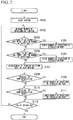
- control unit 35 measures the number of rotations (or power generation amount in the generator 28) of the turbine 26 at given time intervals (Step S102) after the power generation system 20A is started in a predetermined procedure (Step S101).
- the temperature or the flow rate of the heat medium supplied via the heat medium circuit 21 from the heat source may fluctuate greatly. If the temperature or the flow rate of the heat medium fluctuates, the amount of steam generated in the evaporator 25 fluctuates, and as a result, the number of rotations of the turbine 26 fluctuates. Thus, as shown in FIG. 3 , in the turbine 26, a region in which the number of rotations is set with high turbine efficiency is set in advance.
- control unit 35 determines whether or not the number of rotations of the measured turbine 26 is equal to or higher than an upper limit of the region in which the number of rotations is preset (Step S103).
- Step S104 when the measured number of rotations is equal to or higher than the upper limit of the region in which the number of rotations is preset, the number of rotations of the circulation pump 23 is lowered (Step S104).
- the number of rotations of the circulation pump 23 can be changed in a plurality of steps, for example, every given number of rotations (for example, 30 rpm), and when the number of rotations is changed, the number of rotations of the circulation pump 23 can be changed for every one step.
- control unit 35 determines whether or not the measured number of rotations of the turbine 26 is equal to or lower than a lower limit of the region in which the number of rotations is preset (Step S105).
- Step S106 when the measured number of rotations is equal to or lower than the lower limit of the region in which the number of rotations is preset, the number of rotations of the circulation pump 23 is raised (Step S106).
- control unit 35 can perform so-called feedforward control in which heat energy supply fluctuation from the heat source is predicted by monitoring the heat energy supply fluctuation, in addition to the control of the above Steps S101 to S106.
- At least one of the temperature of the heat source, the temperature or the flow rate of the heat medium within the heat medium circuit 21, and the outlet temperature of the evaporator 25 is measured at given time intervals by a measurement device (not shown), and it is determined whether or not the measurement value is increased compared to a temperature or a flow rate, which has been measured immediately before, by a given value or higher (Step S107, S108).
- Step S109 when there is an increase of the given value or higher, it is predicted that the heat energy supply from the heat source tends to increase, and the number of rotations of the circulation pump 23 is raised in advance.
- Step S107 it is determined whether or not the measurement value in Step S107 is decreased compared to the temperature or the flow rate, which has been measured immediately before, by a given value or higher (Step S110).
- Step S111 when there is a decrease of the given value or higher, it is predicted that the heat energy supply from the heat source tends to decrease, and the number of rotations of the circulation pump 23 is lowered in advance (Step S111).
- Step S 112 the processing of the above Steps S102 to S111 is repeated at given time intervals until the operation of the power generation system 20A is ended.
- the number of rotations of the turbine 26 When the number of rotations of the turbine 26 is outside the region in which the number of rotations is set with high predetermined operation efficiency in the above-described manner, the number of rotations of the circulation pump 23 is changed so as to adjust the circulation flow rate of the medium. Accordingly, the turbine 26 can be operated within the region in which the number of rotations is set with high operation efficiency in correspondence with energy fluctuation on a heat source, and power generation can be efficiently performed in the generator 28.
- the medium circuit 22 may include a flow rate regulating valve 70 (refer to FIG. 1 ) that regulates the flow rate of the medium.
- the control unit 35 may regulate the opening degree of the flow rate regulating valve 70 in accordance with the number of rotations of the turbine 26 such that the number of rotations of the turbine 26 falls within the region in which the number of rotations is preset.
- the number of rotations of the circulation pump 23 is increased or decreased on the basis of the amount of increase or decrease in the measurement value in the measurement device.
- the number of rotations of the circulation pump 23 may be increased or decreased on the basis of correlation data between the measurement value and the number of rotations of the circulation pump 23.
- Steps S103 to S106 a configuration may be adopted in which, when it is determined that the measured number of rotations is equal to or lower than the lower limit of the region in which the number of rotations is preset after it is determined whether or not the measured number of rotations is equal to or lower than the lower limit, the number of rotations of the circulation pump is raised, and then, when the measured number of rotations is equal to or higher than the upper limit of the region in which the number of rotations is preset after it is determined whether the measured number of rotations is equal to or higher than the upper limit, the number of rotations of the circulation pump 23 is lowered.
- a configuration may be adopted in which, when the measured number of rotations is equal to or higher than the upper limit of the region in which the number of rotations is preset after it is simultaneously determined whether or not the region in which the number of rotations is preset is equal to or higher than the upper limit and equal to or lower than the lower limit, the number of rotations of the circulation pump 23 is lowered, and when it is determined that the measured number of rotations is equal to or lower than the lower limit, the number of rotations of the circulation pump is raised.
- Steps S107 to S111 a configuration may be adopted in which, at least one of the temperature of the heat source, the temperature or the flow rate of the heat medium within the heat medium circuit 21, and the outlet temperature of the evaporator 25 is measured at given time intervals by the measurement device (not shown), it is determined whether or not the measurement value is decreased compared to a temperature or a flow rate, which has been measured immediately before, by a given value or higher, and when there is a decrease of the given value or higher, it is predicted that the heat energy supply from the heat source tends to decrease and the number of rotations of the circulation pump 23 is lowered in advance.
- a configuration may be adopted in which it is determined whether or not the measurement value is increased compared to the temperature or the flow rate, which has been measured immediately before, by the given value or higher, and when there is an increase of the given value or higher, it is predicted that the heat energy supply from the heat source tends to increase and the number of rotations of the circulation pump 23 is raised in advance.
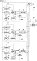
- a power generation system 20B includes a plurality of sets of power generation units 50A, 50B, 50C, ....
- Each of the power generation units 50A, 50B, 50C includes the heat medium circuit 21, the medium circuit 22, the circulation pump 23, the preheater 24, the evaporator 25, the turbine 26, the condenser 27, the generator 28, and the rectifier 29, which are the same as components shown in the above first example.
- the rectifiers 29 of the plurality of sets of power generation units 50A, 50B, 50C, ... are connected to one system-interconnection inverter 30.
- the circulation pump 23 circulates the medium within the medium circuit 22 so as to pass through the preheater 24, the evaporator 25, the turbine 26, and then the condenser 27. Then, a gas medium, which is preheated in the preheater 24 and evaporated and gasified in the evaporator 25, expands within the turbine chamber of the turbine 26, thereby driving the generator 28.
- the generator 28 outputs an alternating current, and this alternating current is converted into a direct current in the rectifier 29 and is output to the system-interconnection inverter 30.
- the direct currents output from the rectifiers 29 of the plurality of power generation units 50A, 50B, 50C, ... are re-converted into an alternating current, and the converted alternating current is output to an external power grid as generated electric power.
- the control unit 35 of the power generation system 20B controls the supply of the heat medium of the heat medium circuit 21, the operation of the circulation pump 23 of the medium circuit 22, while monitoring the operating states or the like of each device that constitutes the power generation system 20B.
- control unit 35 counts integrated values of the operating times of the turbines 26, and performs the operation control of the power generation units 50A, 50B, 50C, ... based on the integrated values.
- Such a power generation system 20B is adapted so as to be able to selectively operate the plurality of power generation units 50A, 50B, 50C, ..., thereby changing the number of units (that is, the number of turbines 26 to be operated) to be operated and stepwisely changing the amount of power generation, in accordance with the amount of input heat energy of the heat medium sent from the heat medium circuit 21 through the control of the control unit 35, or the amount of electric power required on an output side of the power generation system.
- control unit 35 measures the number of rotations (or power generation amount in a generator 28) of a turbine 26 at given time intervals (Step S202) after the power generation system 20B is started in a predetermined procedure (Step S201).
- the control unit 35 determines whether or not the measured number of rotations of the turbine 26 is equal to or higher than an upper limit of the region in which the number of rotations is set (refer to FIG. 3 ) with high turbine efficiency (Step S203).
- Step S204 when the measured number of rotations is equal to or higher than the upper limit of the region in which the number of rotations is preset, the number of units to be operated in the plurality of power generation units 50A, 50B, 50C, ... is decreased by one (Step S204).
- control unit 35 determines whether or not the measured number of rotations of the turbine 26 is equal to or lower than a lower limit of the region in which the number of rotations is preset (Step S205).
- Step S206 when the measured number of rotations is equal to or lower than the lower limit of the region in which the number of rotations is preset, the number of units to be operated in the plurality of power generation units 50A, 50B, 50C, ... is increased by one (Step S206).
- the number of rotations of the turbine 26 is monitored at given time intervals and the number of rotations is outside the region in which the number of rotations is preset, the number of rotations is returned to the number of rotations within the region in which the number of rotations is preset by increasing and decreasing the number of units to be operated in the plurality of power generation units 50A, 50B, 50C, ....
- control unit 35 can perform operation control according to the heat energy supply fluctuation from the heat source, in addition to the control of the above Steps S201 to S206.
- the temperature or the flow rate of the heat medium within the heat medium circuit 21 is measured at given time intervals, and it is determined whether or not the measurement value is increased compared to a temperature or a flow rate, which has been measured immediately before, by a given value or higher (Step S207, S208).
- Step S209 when there is an increase of the given value or higher, the number of units to be operated in the plurality of power generation units 50A, 50B, 50C, ... is increased by one (Step S209).
- Step S207 it is determined whether or not the measurement value in Step S207 is decreased compared to the temperature or the flow rate, which was measured immediately before, by a given value or higher (Step S210).
- Step S211 when there is a decrease of the given value or higher, the number of units to be operated in the plurality of power generation units 50A, 50B, 50C, ... is decreased by one (Step S211).
- Step S212 the processing of the above Steps S202 to S211 is repeated at given time intervals until the operation of the power generation system 20B is ended.
- control unit 35 is adapted so as to preferentially stop operation from a unit equipped with the turbine 26 having the longest operating time among operating units when the number of units to be operated among the plurality of power generation units 50A, 50B, 50C, ... is reduced.
- control unit 35 is adapted so as to preferentially perform operation from a unit equipped with a turbine 26 with the shortest operating time among operating units when the number of units to be operated among the plurality of power generation units 50A, 50B, 50C, ... is increased.
- the number of rotations of the turbine 26 When the number of rotations of the turbine 26 is outside the region in which the number of rotations is set with high predetermined operation efficiency in the above-described manner, the number of units operated in the power generation units 50A, 50B, 50C, ... is changed. Accordingly, the turbine 26 can be operated within the region in which the number of rotations is set with high operation efficiency in correspondence with the energy fluctuations on the heat source, and power generation can be efficiently performed in the generator 28.
- the number of units operated in the power generation units 50A, 50B, 50C, ... is increased or decreased in correspondence to the energy fluctuations on the heat source.
- the medium flow rate in the medium circuit 22 can be regulated in the circulation pump 23 or the flow rate regulating valve 70 in each of the plurality of power generation units 50A, 50B, 50C, ....
- Steps S203 to S206 a configuration may be adopted in which, when it is determined that the measured number of rotations is equal to or lower than the lower limit of the region in which the number of rotations is preset after it is determined whether or not the measured number of rotations is equal to or lower than the lower limit, the number of units operated in the plurality of power generation units 50A, 50B, 50C, ... is increased by one, and then, when the measured number of rotations is equal to or higher than the upper limit of the region in which the number of rotations is preset after it is determined whether the measured number of rotations is equal to or higher than the upper limit, the number of units operated in the plurality of power generation units 50A, 50B, 50C, ... is decreased by one.
- a configuration may be adopted in which, when the measured number of rotations is equal to or higher than the upper limit of the region in which the number of rotations is preset after it is simultaneously determined whether or not the region in which the number of rotations is preset is equal to or higher than the upper limit and equal to or lower than the lower limit, (the number of rotations of the circulation pump 23) the number of units operated in the plurality of power generation units 50A, 50B, 50C, ... is decreased by one, and when it is determined that the measured number of rotations is equal to or lower than the lower limit, the number of rotations of the circulation pump is raised.
- At least one of the temperature of the heat source, the temperature or the flow rate of the heat medium within the heat medium circuit 21, and the outlet temperature of the evaporator 25 may be measured at given time intervals by measurement device (not shown), it may be determined whether or not the measurement value is decreased compared to a temperature or a flow rate, which has been measured immediately before, by a given value or higher, and when there is a decrease of the given value or higher, the number of units operated in the plurality of power generation units 50A, 50B, 50C, ... may be decreased by one.
- the measurement value is increased compared to the temperature or the flow rate, which has been measured immediately before, by the given value or higher, and when there is an increase of the given value or higher, the number of units operated in the plurality of power generation units 50A, 50B, 50C, ... may be increased by one.
- the rectifier 29 may include each system-interconnection inverter 30.
- a power generation system 20C includes a plurality of sets of power generation units 60A, 60B, 60C, ....
- a set of the medium circuit 22, the circulation pump 23, the preheater 24, the evaporator 25, and the condenser 27 is provided for one heat medium circuit 21, and the heat medium circuit 21 branches into a plurality of branched pipes 21a, 21b, 21c, ... between the evaporator 25 and the condenser 27.
- the power generation units 60A, 60B, 60C, ... are formed by each of the branched pipes 21a, 21b, 21c, .. being provided with the turbine 26, the generator 28, and the rectifier 29.
- each rectifier 29 of the plurality of sets of power generation units 60A, 60B, 60C, ... are connected in parallel to one system-interconnection inverter 30.
- the medium sent out from the circulation pump 23 branches into the branched pipes 21a, 21b, 21c, ..., of the power generation units 60A, 60B, 60C, ..., after passing through the preheater 24 and the evaporator 25, within the medium circuit 22.
- this medium drives the turbine 26 to generate electric power using the generator 28, and then returns to the circulation pump 23 through the condenser 27.
- the direct currents output from the rectifiers 29 of the plurality of power generation units 60A, 60B, 60C, ... are re-converted into an alternating current, and the converted alternating current is output to an external power grid as generated electric power.
- the number of units operated in the plurality of power generation units 60A, 60B, 60C, ... is increased or decreased in correspondence with the energy fluctuations on the heat source by the control of the control unit 35. Accordingly, the turbine 26 can be operated within the region in which the number of rotations is set with operation efficiency even if the energy fluctuations on the heat source occur, and power generation can be efficiently performed in the generator 28.
- control unit 35 determines a unit to be operated or stopped on the basis of the operating time of each turbine 26 when the number of units operated among the plurality of power generation units 60A, 60B, 60C, ... is increased or decreased. Accordingly, the operating times of the turbines 26 can be averaged among the plurality of power generation units 60A, 60B, 60C, .... As a result, intervals for the maintenance of the turbines 26 can be extended. Accordingly, maintenance can also be intensively and efficiently maintained by bringing the maintenance timings of all the turbines 26 close to each other.
- exhaust heat from vessels, factories, gas turbines, or the like are used as heat sources, or natural energy, such as geothermal heat, solar heat, temperature difference between cooler deep and warmer shallow ocean waters, and the like is used for power generation as a heat source.
- natural energy such as geothermal heat, solar heat, temperature difference between cooler deep and warmer shallow ocean waters, and the like is used for power generation as a heat source.
- the types of the heat sources are not limited thereto. The types of the heat sources do not matter at all, and are suitable when heat sources in which at least the heat quantity may fluctuate are used.
- the turbine 26 is shown as an expander.
- a scroll-type expander or the like can also be adopted instead of the turbine 26.
- the above embodiment of the invention may include devices that store the operation time of a plurality of generators, and devices that display the operation time.
- the operation time may be displayed on display panels of power generation systems, or may be displayed on display panels outside of power generation systems via the Internet.
- administrators or maintenance workers of the power generation systems can confirm the operation situations of respective generators and perform operation management or maintenance.
Landscapes
- Engineering & Computer Science (AREA)
- Mechanical Engineering (AREA)
- General Engineering & Computer Science (AREA)
- Chemical & Material Sciences (AREA)
- Combustion & Propulsion (AREA)
- Power Engineering (AREA)
- Engine Equipment That Uses Special Cycles (AREA)
- Control Of Turbines (AREA)
- Control Of Eletrric Generators (AREA)
Claims (4)
- Système de production d'énergie comprenant :un circuit de milieu (22) à travers lequel on fait circuler un milieu ;une pompe de circulation (23) configurée pour mettre le milieu sous pression afin que le milieu circule à travers le circuit de milieu (22) ;un évaporateur (25) configuré pour chauffer le milieu sous pression à l'aide de la chaleur d'une source externe afin de faire évaporer le milieu, dans lequel la source externe que la quantité de chaleur est capable de fluctuer ;un détenteur (26) configuré pour être entraîné à l'aide du milieu évaporé par l'évaporateur (25) ;un générateur (28) configuré pour être entraîné à l'aide du détendeur (26) pour produire de l'énergie ; etun dispositif de contrôle de débit (35) configuré pour contrôler le débit du milieu s'écoulant dans le détendeur (26) de sorte que, même lorsque la quantité de la chaleur de la source externe fluctue, le nombre de rotations du détendeur (26) ou du générateur (28) est dans une région dans laquelle le nombre de rotations est préréglé,caractérisé en ce que :une pluralité d'ensembles d'unités de production d'énergie (50A, 50B, 50C) comprenant chacun au moins le détendeur (26) et le générateur (28), sont prévus en parallèle, etle dispositif de contrôle de débit (35) estime des valeurs intégrées des temps de fonctionnement, actionne sélectivement les unités de production d'énergie (50A, 50B, 50C) en fonction des valeurs intégrées, et contrôle le débit du milieu s'écoulant dans le détendeur (26), de sorte que le nombre de rotations du détendeur (26) ou du générateur (28) dans chacune des unités de production d'énergie (50A, 50B, 50C) est dans la région dans laquelle le nombre de rotations est préréglé.
- Système de production d'énergie selon la revendication 1,
dans lequel le dispositif de contrôle de débit (35) contrôle le degré d'ouverture d'une valve de régulation de débit (70) prévue dans le circuit de milieu (22) ou le nombre de rotations de la pompe de circulation (23) afin de contrôler le débit du milieu. - Système de production d'énergie selon la revendication 1 ou 2, comprenant en outre :un dispositif de mesure configuré pour mesurer au moins l'une parmi une température de la source externe, une température ou débit du milieu chauffant fourni de la source externe à l'évaporateur (25), et une température de milieu à une sortie de l'évaporateur (25),dans lequel le dispositif de contrôle de débit (35) contrôle le débit du milieu s'écoulant dans le détendeur (26) en fonction d'un changement d'un résultat de mesure dans le dispositif de mesure.
- Procédé de production d'énergie comprenant les étapes suivantes :produire de l'énergie avec un générateur (28), dans lequel un milieu est mis sous pression pour faire circuler le milieu à travers un circuit de milieu (22), le milieu sous pression est évaporé en utilisant la chaleur d'une source externe, dans lequel la quantité de chaleur de la source externe est susceptible de fluctuer et ensuite le générateur (28) est entraîné à l'aide de la rotation d'un détendeur (26) ;détecter (S202) le nombre de rotations du détendeur (26) ou du générateur (28) ;déterminer (S203, 205) si le nombre de rotations détecté est dans une région dans laquelle le nombre de rotations est préréglé, ou pas ; etcontrôler le débit (S204, S206) du milieu s'écoulant dans le détendeur (26) de sorte que, même lorsque le nombre de rotations détecté n'est pas dans la région dans laquelle le nombre de rotations est préréglé, le nombre de rotations du détendeur (26) ou du générateur (28) est dans la région dans laquelle le nombre de rotations est préréglé,caractérisé en ce que :une pluralité d'ensembles d'unités de production d'énergie (50A, 50B, 50C) comprenant chacun au moins le détendeur (26) et le générateur (28), sont prévus en parallèle, etlors du contrôle du débit (S204, S206) du milieu, un dispositif de contrôle de débit (35) estime des valeurs intégrées des temps de fonctionnement, actionne sélectivement les unités de production d'énergie (50A, 50B, 50C) en fonction des valeurs intégrées, et contrôle le débit du milieu s'écoulant dans le détendeur (26) de sorte que le nombre de rotations du détendeur (26) ou du générateur (28) dans chacune des unités de production d'énergie (50A, 50B, 50C) est dans la région dans laquelle le nombre de rotations est préréglé.
Applications Claiming Priority (2)
| Application Number | Priority Date | Filing Date | Title |
|---|---|---|---|
| JP2012288961A JP6021637B2 (ja) | 2012-12-28 | 2012-12-28 | 発電システム、発電方法 |
| PCT/JP2013/085133 WO2014104307A1 (fr) | 2012-12-28 | 2013-12-27 | Système et procédé de production d'énergie |
Publications (3)
| Publication Number | Publication Date |
|---|---|
| EP2940254A1 EP2940254A1 (fr) | 2015-11-04 |
| EP2940254A4 EP2940254A4 (fr) | 2016-11-16 |
| EP2940254B1 true EP2940254B1 (fr) | 2017-11-22 |
Family
ID=51021376
Family Applications (1)
| Application Number | Title | Priority Date | Filing Date |
|---|---|---|---|
| EP13867524.4A Active EP2940254B1 (fr) | 2012-12-28 | 2013-12-27 | Système et procédé de production d'énergie |
Country Status (5)
| Country | Link |
|---|---|
| US (1) | US20150318810A1 (fr) |
| EP (1) | EP2940254B1 (fr) |
| JP (1) | JP6021637B2 (fr) |
| CN (1) | CN104870757B (fr) |
| WO (1) | WO2014104307A1 (fr) |
Families Citing this family (14)
| Publication number | Priority date | Publication date | Assignee | Title |
|---|---|---|---|---|
| WO2015127132A1 (fr) * | 2014-02-19 | 2015-08-27 | Remy Technologies, Llc | Procédé permettant d'optimiser l'efficacité d'un système de générateurs raccordés en parallèle |
| JP2017014986A (ja) * | 2015-06-30 | 2017-01-19 | アネスト岩田株式会社 | バイナリー発電システムおよびバイナリー発電方法 |
| JP6778475B2 (ja) * | 2015-07-01 | 2020-11-04 | アネスト岩田株式会社 | 発電システムおよび発電方法 |
| US11053847B2 (en) | 2016-12-28 | 2021-07-06 | Malta Inc. | Baffled thermoclines in thermodynamic cycle systems |
| US10801404B2 (en) * | 2016-12-30 | 2020-10-13 | Malta Inc. | Variable pressure turbine |
| JP6991103B2 (ja) * | 2018-06-15 | 2022-01-12 | 日鉄エンジニアリング株式会社 | バイナリー発電システム、およびバイナリー発電システムの制御方法 |
| CN109356674A (zh) * | 2018-12-25 | 2019-02-19 | 大庆特博科技发展有限公司 | 一种可调喷嘴数量的有机工质透平 |
| EP4296477A3 (fr) | 2020-08-12 | 2024-02-28 | Malta Inc. | Système d'accumulation d'énergie thermique par pompage doté d'une turbomachine modulaire |
| US11486305B2 (en) | 2020-08-12 | 2022-11-01 | Malta Inc. | Pumped heat energy storage system with load following |
| US11454167B1 (en) | 2020-08-12 | 2022-09-27 | Malta Inc. | Pumped heat energy storage system with hot-side thermal integration |
| CN113036812B (zh) * | 2021-04-28 | 2023-05-12 | 南方海洋科学与工程广东省实验室(湛江) | 一种用于海洋温差能发电的并网系统 |
| EP4430285A4 (fr) | 2021-12-14 | 2025-11-26 | Malta Inc | Système de stockage d'énergie thermique pompée intégré à une unité de génération d'énergie au charbon |
| JP2023157795A (ja) * | 2022-04-15 | 2023-10-26 | 学校法人国士舘 | 流体膨張機及び流体膨張ユニット |
| CN117662265B (zh) * | 2024-01-03 | 2024-07-02 | 华商博雅(北京)科技有限公司 | 一种orc发电过程中温度稳定调节方法及系统 |
Family Cites Families (25)
| Publication number | Priority date | Publication date | Assignee | Title |
|---|---|---|---|---|
| US4013877A (en) * | 1974-08-13 | 1977-03-22 | Westinghouse Electric Corporation | Combined cycle electric power plant with a steam turbine having an improved valve control system |
| US4412422A (en) * | 1981-08-31 | 1983-11-01 | General Electric Company | Apparatus and method for controlling a multi-turbine installation |
| JPS59131710A (ja) * | 1983-01-18 | 1984-07-28 | Mitsui Eng & Shipbuild Co Ltd | 舶用タ−ボ発電機制御装置 |
| JPS6088806A (ja) * | 1983-10-21 | 1985-05-18 | Mitsui Eng & Shipbuild Co Ltd | 内燃機関の廃熱回収装置 |
| IL88571A (en) * | 1988-12-02 | 1998-06-15 | Ormat Turbines 1965 Ltd | Method of and apparatus for producing power using steam |
| US6784565B2 (en) * | 1997-09-08 | 2004-08-31 | Capstone Turbine Corporation | Turbogenerator with electrical brake |
| US7019412B2 (en) * | 2002-04-16 | 2006-03-28 | Research Sciences, L.L.C. | Power generation methods and systems |
| JP3901608B2 (ja) * | 2002-07-24 | 2007-04-04 | 本田技研工業株式会社 | ランキンサイクル装置 |
| JP3901609B2 (ja) * | 2002-07-25 | 2007-04-04 | 本田技研工業株式会社 | ランキンサイクル装置 |
| US7290393B2 (en) * | 2004-05-06 | 2007-11-06 | Utc Power Corporation | Method for synchronizing an induction generator of an ORC plant to a grid |
| JP2005337065A (ja) * | 2004-05-25 | 2005-12-08 | Toyota Industries Corp | ランキンサイクル装置 |
| JP4829526B2 (ja) | 2005-04-22 | 2011-12-07 | 株式会社荏原製作所 | 排熱利用システム及び運転方法 |
| JP4883935B2 (ja) | 2005-05-09 | 2012-02-22 | 株式会社荏原製作所 | 排熱利用システム及びその運転方法 |
| JP5116949B2 (ja) | 2005-05-09 | 2013-01-09 | 株式会社荏原製作所 | 排熱利用システム、及びその運転方法 |
| JP4714159B2 (ja) * | 2007-01-17 | 2011-06-29 | ヤンマー株式会社 | ランキンサイクル動力回収装置 |
| WO2009101977A1 (fr) * | 2008-02-14 | 2009-08-20 | Sanden Corporation | Dispositif d'utilisation de chaleur résiduelle pour moteur à combustion interne |
| US8353160B2 (en) * | 2008-06-01 | 2013-01-15 | John Pesce | Thermo-electric engine |
| JP5001928B2 (ja) * | 2008-10-20 | 2012-08-15 | サンデン株式会社 | 内燃機関の廃熱回収システム |
| JP5221443B2 (ja) * | 2009-05-08 | 2013-06-26 | 株式会社東芝 | 一軸型複合サイクル発電プラントの起動方法および一軸型複合サイクル発電プラント |
| CN101929360B (zh) * | 2010-09-02 | 2013-08-21 | 上海交通大学 | 基于能量梯级利用的中低温热源发电装置及其热循环方法 |
| US8667799B2 (en) * | 2011-07-25 | 2014-03-11 | Ormat Technologies Inc. | Cascaded power plant using low and medium temperature source fluid |
| CN102619641A (zh) * | 2012-04-12 | 2012-08-01 | 北京工业大学 | 同时利用内燃机排气和冷却余热的发电系统及控制方法 |
| CN102787889A (zh) * | 2012-08-14 | 2012-11-21 | 天津大学 | 柴油机排气余热双效回收系统 |
| JP6187852B2 (ja) * | 2012-12-28 | 2017-08-30 | 三菱重工業株式会社 | 発電システムのメンテナンス方法 |
| JP5964229B2 (ja) * | 2012-12-28 | 2016-08-03 | 三菱重工業株式会社 | 発電システム |
-
2012
- 2012-12-28 JP JP2012288961A patent/JP6021637B2/ja active Active
-
2013
- 2013-12-27 EP EP13867524.4A patent/EP2940254B1/fr active Active
- 2013-12-27 WO PCT/JP2013/085133 patent/WO2014104307A1/fr not_active Ceased
- 2013-12-27 US US14/650,601 patent/US20150318810A1/en not_active Abandoned
- 2013-12-27 CN CN201380066060.7A patent/CN104870757B/zh active Active
Non-Patent Citations (1)
| Title |
|---|
| None * |
Also Published As
| Publication number | Publication date |
|---|---|
| WO2014104307A1 (fr) | 2014-07-03 |
| CN104870757B (zh) | 2016-08-24 |
| EP2940254A1 (fr) | 2015-11-04 |
| CN104870757A (zh) | 2015-08-26 |
| JP6021637B2 (ja) | 2016-11-09 |
| EP2940254A4 (fr) | 2016-11-16 |
| JP2014129797A (ja) | 2014-07-10 |
| US20150318810A1 (en) | 2015-11-05 |
Similar Documents
| Publication | Publication Date | Title |
|---|---|---|
| EP2940254B1 (fr) | Système et procédé de production d'énergie | |
| US8375716B2 (en) | Operating a sub-sea organic Rankine cycle (ORC) system using individual pressure vessels | |
| EP2940259B1 (fr) | Système de génération d'énergie et procédé de maintenance associé | |
| US9322300B2 (en) | Thermal cycle energy and pumping recovery system | |
| EP2540995B1 (fr) | Appareil de production d'énergie | |
| JP4875546B2 (ja) | 排熱発電装置、排熱発電装置の作動媒体蒸気過熱度制御方法 | |
| JP2005518493A (ja) | 廃熱及び太陽光源から電気及び動力の生成のためのシステム及び方法 | |
| KR101028634B1 (ko) | 발전소의 출력증강으로 발생한 잉여증기를 이용한 보조발전시스템 | |
| JP5964229B2 (ja) | 発電システム | |
| EP3604767A1 (fr) | Dispositif de production d'énergie à stockage d'air comprimé | |
| Włodarski | Control of a vapour microturbine set in cogeneration applications | |
| KR20140143390A (ko) | 선박의 폐열 회수 시스템 | |
| KR20130128903A (ko) | Orc 발전시스템의 안전장치 | |
| US20140318131A1 (en) | Heat sources for thermal cycles | |
| JP5192736B2 (ja) | 排熱発電装置、排熱発電装置の運転方法 | |
| JP2013181456A (ja) | バイナリ発電装置およびその制御方法 | |
| EP3112622B1 (fr) | Système de génération de puissance binaire et procédé de génération de puissance binaire | |
| JP2007006684A (ja) | 発電装置 | |
| KR102186857B1 (ko) | 계통 연계 시스템, 그것에 사용하는 발전 컨트롤러, 및 그 운전 방법 | |
| JP2019019797A (ja) | 熱電併給システム及び熱電併給システムの運転方法 | |
| US20180066547A1 (en) | System and method for generation of electricity from any heat sources | |
| EP3112621B1 (fr) | Système de génération d'énergie et procédé de génération d'énergie | |
| WO2016170653A1 (fr) | Système de turbine à vapeur | |
| RU2452899C2 (ru) | Система рекуперации избыточного магистрального давления в тепловых пунктах сетей теплоснабжения | |
| JP2012207533A (ja) | エネルギー回収装置およびエネルギー回収装置の運転方法 |
Legal Events
| Date | Code | Title | Description |
|---|---|---|---|
| PUAI | Public reference made under article 153(3) epc to a published international application that has entered the european phase |
Free format text: ORIGINAL CODE: 0009012 |
|
| 17P | Request for examination filed |
Effective date: 20150609 |
|
| AK | Designated contracting states |
Kind code of ref document: A1 Designated state(s): AL AT BE BG CH CY CZ DE DK EE ES FI FR GB GR HR HU IE IS IT LI LT LU LV MC MK MT NL NO PL PT RO RS SE SI SK SM TR |
|
| AX | Request for extension of the european patent |
Extension state: BA ME |
|
| DAX | Request for extension of the european patent (deleted) | ||
| A4 | Supplementary search report drawn up and despatched |
Effective date: 20161013 |
|
| RIC1 | Information provided on ipc code assigned before grant |
Ipc: F01K 23/10 20060101ALI20161007BHEP Ipc: F01K 25/10 20060101ALI20161007BHEP Ipc: F01D 17/24 20060101AFI20161007BHEP Ipc: F01K 13/02 20060101ALI20161007BHEP Ipc: F01K 27/02 20060101ALI20161007BHEP Ipc: F02C 6/18 20060101ALI20161007BHEP |
|
| GRAP | Despatch of communication of intention to grant a patent |
Free format text: ORIGINAL CODE: EPIDOSNIGR1 |
|
| INTG | Intention to grant announced |
Effective date: 20170425 |
|
| GRAS | Grant fee paid |
Free format text: ORIGINAL CODE: EPIDOSNIGR3 |
|
| GRAJ | Information related to disapproval of communication of intention to grant by the applicant or resumption of examination proceedings by the epo deleted |
Free format text: ORIGINAL CODE: EPIDOSDIGR1 |
|
| GRAL | Information related to payment of fee for publishing/printing deleted |
Free format text: ORIGINAL CODE: EPIDOSDIGR3 |
|
| GRAR | Information related to intention to grant a patent recorded |
Free format text: ORIGINAL CODE: EPIDOSNIGR71 |
|
| INTC | Intention to grant announced (deleted) | ||
| GRAA | (expected) grant |
Free format text: ORIGINAL CODE: 0009210 |
|
| AK | Designated contracting states |
Kind code of ref document: B1 Designated state(s): AL AT BE BG CH CY CZ DE DK EE ES FI FR GB GR HR HU IE IS IT LI LT LU LV MC MK MT NL NO PL PT RO RS SE SI SK SM TR |
|
| INTG | Intention to grant announced |
Effective date: 20171013 |
|
| REG | Reference to a national code |
Ref country code: GB Ref legal event code: FG4D |
|
| REG | Reference to a national code |
Ref country code: CH Ref legal event code: EP |
|
| REG | Reference to a national code |
Ref country code: IE Ref legal event code: FG4D |
|
| REG | Reference to a national code |
Ref country code: AT Ref legal event code: REF Ref document number: 948609 Country of ref document: AT Kind code of ref document: T Effective date: 20171215 |
|
| REG | Reference to a national code |
Ref country code: DE Ref legal event code: R096 Ref document number: 602013029968 Country of ref document: DE |
|
| REG | Reference to a national code |
Ref country code: NL Ref legal event code: MP Effective date: 20171122 |
|
| REG | Reference to a national code |
Ref country code: LT Ref legal event code: MG4D |
|
| REG | Reference to a national code |
Ref country code: AT Ref legal event code: MK05 Ref document number: 948609 Country of ref document: AT Kind code of ref document: T Effective date: 20171122 |
|
| PG25 | Lapsed in a contracting state [announced via postgrant information from national office to epo] |
Ref country code: FI Free format text: LAPSE BECAUSE OF FAILURE TO SUBMIT A TRANSLATION OF THE DESCRIPTION OR TO PAY THE FEE WITHIN THE PRESCRIBED TIME-LIMIT Effective date: 20171122 Ref country code: SE Free format text: LAPSE BECAUSE OF FAILURE TO SUBMIT A TRANSLATION OF THE DESCRIPTION OR TO PAY THE FEE WITHIN THE PRESCRIBED TIME-LIMIT Effective date: 20171122 Ref country code: ES Free format text: LAPSE BECAUSE OF FAILURE TO SUBMIT A TRANSLATION OF THE DESCRIPTION OR TO PAY THE FEE WITHIN THE PRESCRIBED TIME-LIMIT Effective date: 20171122 Ref country code: NL Free format text: LAPSE BECAUSE OF FAILURE TO SUBMIT A TRANSLATION OF THE DESCRIPTION OR TO PAY THE FEE WITHIN THE PRESCRIBED TIME-LIMIT Effective date: 20171122 Ref country code: LT Free format text: LAPSE BECAUSE OF FAILURE TO SUBMIT A TRANSLATION OF THE DESCRIPTION OR TO PAY THE FEE WITHIN THE PRESCRIBED TIME-LIMIT Effective date: 20171122 Ref country code: NO Free format text: LAPSE BECAUSE OF FAILURE TO SUBMIT A TRANSLATION OF THE DESCRIPTION OR TO PAY THE FEE WITHIN THE PRESCRIBED TIME-LIMIT Effective date: 20180222 |
|
| PG25 | Lapsed in a contracting state [announced via postgrant information from national office to epo] |
Ref country code: LV Free format text: LAPSE BECAUSE OF FAILURE TO SUBMIT A TRANSLATION OF THE DESCRIPTION OR TO PAY THE FEE WITHIN THE PRESCRIBED TIME-LIMIT Effective date: 20171122 Ref country code: AT Free format text: LAPSE BECAUSE OF FAILURE TO SUBMIT A TRANSLATION OF THE DESCRIPTION OR TO PAY THE FEE WITHIN THE PRESCRIBED TIME-LIMIT Effective date: 20171122 Ref country code: RS Free format text: LAPSE BECAUSE OF FAILURE TO SUBMIT A TRANSLATION OF THE DESCRIPTION OR TO PAY THE FEE WITHIN THE PRESCRIBED TIME-LIMIT Effective date: 20171122 Ref country code: HR Free format text: LAPSE BECAUSE OF FAILURE TO SUBMIT A TRANSLATION OF THE DESCRIPTION OR TO PAY THE FEE WITHIN THE PRESCRIBED TIME-LIMIT Effective date: 20171122 Ref country code: BG Free format text: LAPSE BECAUSE OF FAILURE TO SUBMIT A TRANSLATION OF THE DESCRIPTION OR TO PAY THE FEE WITHIN THE PRESCRIBED TIME-LIMIT Effective date: 20180222 Ref country code: GR Free format text: LAPSE BECAUSE OF FAILURE TO SUBMIT A TRANSLATION OF THE DESCRIPTION OR TO PAY THE FEE WITHIN THE PRESCRIBED TIME-LIMIT Effective date: 20180223 |
|
| REG | Reference to a national code |
Ref country code: DE Ref legal event code: R119 Ref document number: 602013029968 Country of ref document: DE |
|
| PG25 | Lapsed in a contracting state [announced via postgrant information from national office to epo] |
Ref country code: CZ Free format text: LAPSE BECAUSE OF FAILURE TO SUBMIT A TRANSLATION OF THE DESCRIPTION OR TO PAY THE FEE WITHIN THE PRESCRIBED TIME-LIMIT Effective date: 20171122 Ref country code: DK Free format text: LAPSE BECAUSE OF FAILURE TO SUBMIT A TRANSLATION OF THE DESCRIPTION OR TO PAY THE FEE WITHIN THE PRESCRIBED TIME-LIMIT Effective date: 20171122 Ref country code: CY Free format text: LAPSE BECAUSE OF FAILURE TO SUBMIT A TRANSLATION OF THE DESCRIPTION OR TO PAY THE FEE WITHIN THE PRESCRIBED TIME-LIMIT Effective date: 20171122 Ref country code: EE Free format text: LAPSE BECAUSE OF FAILURE TO SUBMIT A TRANSLATION OF THE DESCRIPTION OR TO PAY THE FEE WITHIN THE PRESCRIBED TIME-LIMIT Effective date: 20171122 Ref country code: SK Free format text: LAPSE BECAUSE OF FAILURE TO SUBMIT A TRANSLATION OF THE DESCRIPTION OR TO PAY THE FEE WITHIN THE PRESCRIBED TIME-LIMIT Effective date: 20171122 |
|
| REG | Reference to a national code |
Ref country code: CH Ref legal event code: PL |
|
| PG25 | Lapsed in a contracting state [announced via postgrant information from national office to epo] |
Ref country code: RO Free format text: LAPSE BECAUSE OF FAILURE TO SUBMIT A TRANSLATION OF THE DESCRIPTION OR TO PAY THE FEE WITHIN THE PRESCRIBED TIME-LIMIT Effective date: 20171122 Ref country code: SM Free format text: LAPSE BECAUSE OF FAILURE TO SUBMIT A TRANSLATION OF THE DESCRIPTION OR TO PAY THE FEE WITHIN THE PRESCRIBED TIME-LIMIT Effective date: 20171122 Ref country code: PL Free format text: LAPSE BECAUSE OF FAILURE TO SUBMIT A TRANSLATION OF THE DESCRIPTION OR TO PAY THE FEE WITHIN THE PRESCRIBED TIME-LIMIT Effective date: 20171122 |
|
| REG | Reference to a national code |
Ref country code: IE Ref legal event code: MM4A |
|
| PG25 | Lapsed in a contracting state [announced via postgrant information from national office to epo] |
Ref country code: MT Free format text: LAPSE BECAUSE OF NON-PAYMENT OF DUE FEES Effective date: 20171227 Ref country code: LU Free format text: LAPSE BECAUSE OF NON-PAYMENT OF DUE FEES Effective date: 20171227 |
|
| PLBE | No opposition filed within time limit |
Free format text: ORIGINAL CODE: 0009261 |
|
| REG | Reference to a national code |
Ref country code: FR Ref legal event code: ST Effective date: 20180831 |
|
| STAA | Information on the status of an ep patent application or granted ep patent |
Free format text: STATUS: NO OPPOSITION FILED WITHIN TIME LIMIT |
|
| REG | Reference to a national code |
Ref country code: BE Ref legal event code: MM Effective date: 20171231 |
|
| GBPC | Gb: european patent ceased through non-payment of renewal fee |
Effective date: 20180222 |
|
| 26N | No opposition filed |
Effective date: 20180823 |
|
| PG25 | Lapsed in a contracting state [announced via postgrant information from national office to epo] |
Ref country code: DE Free format text: LAPSE BECAUSE OF NON-PAYMENT OF DUE FEES Effective date: 20180703 Ref country code: IE Free format text: LAPSE BECAUSE OF NON-PAYMENT OF DUE FEES Effective date: 20171227 Ref country code: FR Free format text: LAPSE BECAUSE OF NON-PAYMENT OF DUE FEES Effective date: 20180122 |
|
| PG25 | Lapsed in a contracting state [announced via postgrant information from national office to epo] |
Ref country code: LI Free format text: LAPSE BECAUSE OF NON-PAYMENT OF DUE FEES Effective date: 20171231 Ref country code: CH Free format text: LAPSE BECAUSE OF NON-PAYMENT OF DUE FEES Effective date: 20171231 Ref country code: SI Free format text: LAPSE BECAUSE OF FAILURE TO SUBMIT A TRANSLATION OF THE DESCRIPTION OR TO PAY THE FEE WITHIN THE PRESCRIBED TIME-LIMIT Effective date: 20171122 Ref country code: BE Free format text: LAPSE BECAUSE OF NON-PAYMENT OF DUE FEES Effective date: 20171231 |
|
| PG25 | Lapsed in a contracting state [announced via postgrant information from national office to epo] |
Ref country code: GB Free format text: LAPSE BECAUSE OF NON-PAYMENT OF DUE FEES Effective date: 20180222 |
|
| PG25 | Lapsed in a contracting state [announced via postgrant information from national office to epo] |
Ref country code: HU Free format text: LAPSE BECAUSE OF FAILURE TO SUBMIT A TRANSLATION OF THE DESCRIPTION OR TO PAY THE FEE WITHIN THE PRESCRIBED TIME-LIMIT; INVALID AB INITIO Effective date: 20131227 Ref country code: MC Free format text: LAPSE BECAUSE OF FAILURE TO SUBMIT A TRANSLATION OF THE DESCRIPTION OR TO PAY THE FEE WITHIN THE PRESCRIBED TIME-LIMIT Effective date: 20171122 |
|
| PG25 | Lapsed in a contracting state [announced via postgrant information from national office to epo] |
Ref country code: MK Free format text: LAPSE BECAUSE OF FAILURE TO SUBMIT A TRANSLATION OF THE DESCRIPTION OR TO PAY THE FEE WITHIN THE PRESCRIBED TIME-LIMIT Effective date: 20171122 |
|
| PG25 | Lapsed in a contracting state [announced via postgrant information from national office to epo] |
Ref country code: PT Free format text: LAPSE BECAUSE OF FAILURE TO SUBMIT A TRANSLATION OF THE DESCRIPTION OR TO PAY THE FEE WITHIN THE PRESCRIBED TIME-LIMIT Effective date: 20171122 |
|
| PG25 | Lapsed in a contracting state [announced via postgrant information from national office to epo] |
Ref country code: AL Free format text: LAPSE BECAUSE OF FAILURE TO SUBMIT A TRANSLATION OF THE DESCRIPTION OR TO PAY THE FEE WITHIN THE PRESCRIBED TIME-LIMIT Effective date: 20171122 Ref country code: IS Free format text: LAPSE BECAUSE OF FAILURE TO SUBMIT A TRANSLATION OF THE DESCRIPTION OR TO PAY THE FEE WITHIN THE PRESCRIBED TIME-LIMIT Effective date: 20180322 |
|
| PGFP | Annual fee paid to national office [announced via postgrant information from national office to epo] |
Ref country code: IT Payment date: 20251121 Year of fee payment: 13 |
|
| PGFP | Annual fee paid to national office [announced via postgrant information from national office to epo] |
Ref country code: TR Payment date: 20251225 Year of fee payment: 13 |