EP2940281B1 - Zylinderkopf und motor - Google Patents
Zylinderkopf und motor Download PDFInfo
- Publication number
- EP2940281B1 EP2940281B1 EP13875482.5A EP13875482A EP2940281B1 EP 2940281 B1 EP2940281 B1 EP 2940281B1 EP 13875482 A EP13875482 A EP 13875482A EP 2940281 B1 EP2940281 B1 EP 2940281B1
- Authority
- EP
- European Patent Office
- Prior art keywords
- cylinder
- combustion chamber
- valve
- intake
- central axis
- Prior art date
- Legal status (The legal status is an assumption and is not a legal conclusion. Google has not performed a legal analysis and makes no representation as to the accuracy of the status listed.)
- Active
Links
Images

Classifications
-
- F—MECHANICAL ENGINEERING; LIGHTING; HEATING; WEAPONS; BLASTING
- F02—COMBUSTION ENGINES; HOT-GAS OR COMBUSTION-PRODUCT ENGINE PLANTS
- F02F—CYLINDERS, PISTONS OR CASINGS, FOR COMBUSTION ENGINES; ARRANGEMENTS OF SEALINGS IN COMBUSTION ENGINES
- F02F1/00—Cylinders; Cylinder heads
- F02F1/24—Cylinder heads
- F02F1/42—Shape or arrangement of intake or exhaust channels in cylinder heads
- F02F1/4285—Shape or arrangement of intake or exhaust channels in cylinder heads of both intake and exhaust channel
-
- F—MECHANICAL ENGINEERING; LIGHTING; HEATING; WEAPONS; BLASTING
- F02—COMBUSTION ENGINES; HOT-GAS OR COMBUSTION-PRODUCT ENGINE PLANTS
- F02F—CYLINDERS, PISTONS OR CASINGS, FOR COMBUSTION ENGINES; ARRANGEMENTS OF SEALINGS IN COMBUSTION ENGINES
- F02F1/00—Cylinders; Cylinder heads
- F02F1/24—Cylinder heads
- F02F1/42—Shape or arrangement of intake or exhaust channels in cylinder heads
-
- F—MECHANICAL ENGINEERING; LIGHTING; HEATING; WEAPONS; BLASTING
- F01—MACHINES OR ENGINES IN GENERAL; ENGINE PLANTS IN GENERAL; STEAM ENGINES
- F01L—CYCLICALLY OPERATING VALVES FOR MACHINES OR ENGINES
- F01L1/00—Valve-gear or valve arrangements, e.g. lift-valve gear
- F01L1/26—Valve-gear or valve arrangements, e.g. lift-valve gear characterised by the provision of two or more valves operated simultaneously by same transmitting-gear; peculiar to machines or engines with more than two lift-valves per cylinder
-
- F—MECHANICAL ENGINEERING; LIGHTING; HEATING; WEAPONS; BLASTING
- F01—MACHINES OR ENGINES IN GENERAL; ENGINE PLANTS IN GENERAL; STEAM ENGINES
- F01L—CYCLICALLY OPERATING VALVES FOR MACHINES OR ENGINES
- F01L3/00—Lift-valve, i.e. cut-off apparatus with closure members having at least a component of their opening and closing motion perpendicular to the closing faces; Parts or accessories thereof
- F01L3/06—Valve members or valve-seats with means for guiding or deflecting the medium controlled thereby, e.g. producing a rotary motion of the drawn-in cylinder charge
-
- Y—GENERAL TAGGING OF NEW TECHNOLOGICAL DEVELOPMENTS; GENERAL TAGGING OF CROSS-SECTIONAL TECHNOLOGIES SPANNING OVER SEVERAL SECTIONS OF THE IPC; TECHNICAL SUBJECTS COVERED BY FORMER USPC CROSS-REFERENCE ART COLLECTIONS [XRACs] AND DIGESTS
- Y02—TECHNOLOGIES OR APPLICATIONS FOR MITIGATION OR ADAPTATION AGAINST CLIMATE CHANGE
- Y02T—CLIMATE CHANGE MITIGATION TECHNOLOGIES RELATED TO TRANSPORTATION
- Y02T10/00—Road transport of goods or passengers
- Y02T10/10—Internal combustion engine [ICE] based vehicles
- Y02T10/12—Improving ICE efficiencies
Definitions
- the present invention relates to an engine including a cylinder head.
- a gas engine performing combustion operation using a gas fuel (fuel gas) such as natural gas or municipal gas is known as an exemplary engine.
- a gas fuel such as natural gas or municipal gas
- Such a gas engine can obtain high efficiency and high output, and thus is widely used for engines for continuous and emergency power generation, engines for construction machinery, engines mounted in ships, railroads, or the like.
- a fuel gas is supplied to air introduced from an intake pipe, and thereby a gas mixture composed of the air and the fuel gas is created.
- This gas mixture is compressed by a compressor of a supercharger, has its flow rate adjusted by a throttle valve, and then is supplied to a combustion chamber via an intake port. Then, the gas mixture is ignited in the combustion chamber, and thereby the combustion operation is performed.
- An exhaust gas is discharged via an exhaust port. Further, the intake port and the exhaust port are each formed in a cylinder head.
- a gas engine having a cylinder head equipped with an auxiliary chamber for ignition has been known (e.g., see Japanese Unexamined Patent Application, First Publication No. 2004-251213 ).
- a gas of the auxiliary chamber is ignited by sparks of a spark plug in the auxiliary chamber.
- generated flames are ejected into a main combustion chamber, and a fuel-air mixture in the main combustion chamber is ignited. Thereby, the combustion operation is performed.
- FIG. 4 a partial longitudinal sectional view of a gas engine 1 is shown in Fig. 4 .
- a cylinder head 2 of the gas engine 1 is formed with an intake port 4 that is opened toward a combustion chamber 3.
- An opening 5 of the intake port 4 is formed with a seat surface 5 a with which an outer circumferential surface of an intake valve 6 comes into contact.
- a portion of the opening 5 of the intake port 4 wherein the portion is closer to the side of the combustion chamber 3, than the seat surface 5a, is formed with a tapered surface 5b that is increased in diameter toward the combustion chamber 3 in order to secure a flow coefficient.
- EP 2 108 788 A1 , JP S58 137804 U and JP S61 91046 U disclose the pre-characterizing features of claim 1 and represent the closest prior art.
- the intake valve 6 is located immediately adjacent to the inside of an inner wall surface 8 of a cylinder block 7 defining the combustion chamber 3. For this reason, an opening edge of the tapered surface 5b located closer to the side of the combustion chamber 3, than the seat surface 5a, against which the intake valve 6 abuts, is partly located at a radial outer side of the inner wall surface 8 relative to the inner wall surface 8 of the cylinder block 7.
- the present invention has been made in consideration of the above circumstances and an object of the present invention is to provide an engine with a cylinder head capable of improving combustion efficiency.
- the present invention employs the following means in order to solve the above problem.
- a cylinder head of the engine includes a cylinder head body provided with intake and exhaust ports opened toward a combustion chamber and capable of being closed by valves, the intake and exhaust ports being separated from each other in a circumferential direction around a cylinder central axis; wherein an opening section of at least one of the intake and exhaust ports facing the combustion chamber is provided with a seat surface centered on a valve axis and a tapered surface disposed closer to the combustion chamber than the seat surface, the tapered surface being gradually increased in diameter as close to the combustion chamber, and a central axis of the tapered surface is disposed eccentrically from the valve axis toward the cylinder central axis.
- the central axis of the tapered surface is located closer to the cylinder central axis than that of the seat surface, the occurrence of the unnecessary increase in volume that does not contribute to combustion at an opening section of the intake or exhaust port can be suppressed.
- the engine of the present invention includes the cylinder head and a cylinder block having an inner wall surface forming the combustion chamber along with the cylinder head.
- the tapered surface is positioned inside the inner wall surface of the cylinder block when viewed in the cylinder axis of the engine.
- the combustion efficiency can be improved.
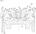
- gas engine (engine) 100 of an embodiment of the present invention will be described with reference to Figs. 1 to 3 .
- the gas engine 100 is equipped with a cylinder block 10, a piston 20, a cylinder head 30, an antechamber cap 80, intake valves 60, and exhaust valves 70.
- the cylinder block 10 is a tubular member extending in a direction of a cylinder central axis O1.
- An inner wall surface 11 of the cylinder block 10 has a circular cross section perpendicular to the cylinder central axis O1, and is shaped as a cylindrical surface whose inner diameter is uniform in the direction of the cylinder central axis O1.
- the piston 20 is configured to close the side of one end (lower side in Fig. 1 ) of the cylinder block 10 and is disposed inside the cylinder block 10.
- the piston 20 is disposed to enable reciprocation in the direction of the cylinder central axis O1.
- the piston 20 is connected to one end of a connecting rod (not shown), and the other end of the connecting rod is connected to a crankshaft (not shown). Thereby, the reciprocation of the piston 20 is transmitted as rotational motion to the crankshaft via the connecting rod.
- the cylinder head 30 is a member disposed at the other end (upper side in Fig. 1 ) of the cylinder block 10.
- the cylinder head 30 has a cylinder head body 31 shaped as a lid closing the side of the other end of the cylinder block 10.
- a surface of the cylinder head body 31 which faces the side of the cylinder block 10 becomes a roof surface 32 having a flat shape perpendicular to the cylinder central axis O1.
- the roof surface 32 of the cylinder head body 31 abuts an end face 12 of the cylinder block 10. Thereby, the cylinder head body 31 is integrally fixed to the cylinder block 10.
- a combustion chamber 15 is defined in the cylinder block 10 by the roof surface 32 of the cylinder head body 31, the inner wall surface 11 of the cylinder block 10, and the piston 20.
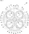
- the roof surface 32 of the cylinder head 30 is formed with intake ports 40 and exhaust ports 50, both of which are opened toward the combustion chamber 15, so as to pass through the cylinder head 30.
- the intake ports 40 and the exhaust ports 50 are each formed in a pair.
- the intake ports 40 and the exhaust ports 50 are disposed at intervals in a circumferential direction around the cylinder central axis O1.
- the pair of intake ports 40 is disposed to be adjacent to each other in the circumferential direction around the cylinder central axis O1.
- the pair of exhaust ports 50 is also disposed to be adjacent to each other in the circumferential direction around the cylinder central axis O1.
- Ends (not shown) of the intake ports 40 which are located at the side opposite to the side of the combustion chamber 15 are connected to a gas mixture passage (not shown), and a gas mixture of air and a combustion gas is supplied to the intake ports 40 via the gas mixture passage.
- Ends (not shown) of the exhaust ports 50 which are located at the side opposite to the side of the combustion chamber 15 are connected to an exhaust gas passage (not shown), and an exhaust gas of the gas mixture provided for combustion in the combustion chamber 15 is discharged outside via the exhaust gas passage.
- the antechamber cap 80 is disposed to be buried in the center of the roof surface 32 of the cylinder head 30, and a part thereof protrudes inside the combustion chamber 15.
- the antechamber cap 80 is formed centered on the cylinder central axis O1, and a hollow portion inside thereof becomes an antechamber 81. Further, the antechamber cap 80 is formed with a plurality of ejection holes 83 that allow the antechamber 81 and the combustion chamber 15 to communicate with each other.
- An antechamber gas is supplied to the antechamber 81 in the antechamber cap 80 via an antechamber gas passage (not shown). Further, the antechamber 81 is provided with a spark plug 82 that generates sparks. The antechamber gas in the antechamber 81 is ignited by the sparks of the spark plug 82, and thereby generated flames are ejected into the combustion chamber 15 via the ejection holes 83.
- the intake valves 60 and the exhaust valves 70 are valves that reciprocate in directions of respective valve axes O2 and thereby open and close the intake ports 40 and the exhaust valves 70.
- the intake valves 60 are provided inside the intake ports 40.
- the intake valves 60 are capable of being closed the intake ports 40.
- the exhaust valves 70 are provided inside the exhaust ports 50.
- the exhaust valves 70 are capable of being closed the exhaust ports 50.
- the valve axes O2 of the intake valves 60 and the exhaust valves 70 are located in the intake ports 40 and the exhaust ports 50 respectively.
- the valve axes O2 of the intake valves 60 and the exhaust valves 70 are parallel to the cylinder central axis O1.
- the intake valves 60 and the exhaust valves 70 have valve stems 61 and 71 and valve faces 62 and 72 that are formed centered on the respective valve axes O2.
- valve stems 61 and 71 are rod-like members extending along the valve axes O2.
- the valve stems 61 and 71 enable reciprocation along stem guides (not shown) formed in the cylinder head 30 in the directions of the axes O2.
- valve faces 62 is integrally provided at end of the valve stems 61 which is located at one side in the direction of the valve axis O2, that is, at the side of the combustion chamber 15.
- the valve faces 72 is integrally provided at end of the valve stems 71 which is located at one side in the direction of the valve axis O2, that is, at the side of the combustion chamber 15.
- the valve faces 62 and 72 are outer circumferential surfaces thereof become face surfaces 63 and 73, each of which is gradually increased in diameter toward the one side in the direction of the valve axis O2.
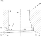
- opening sections 41 and 51 of the intake valve 60 and the exhaust valve 70, which face the combustion chamber 15, are formed with seat surfaces 46 and 56 and tapered surfaces 43 and 53, respectively.
- An enlarged view of the opening section 41 of the intake port 40 is shown in Fig. 2 , but the exhaust port 50 also has the same constitution.
- the seat surfaces 46 and 56 are surfaces on which the face surfaces 63 and 73 of the intake and exhaust valves 60 and 70 abut throughout the circumferential areas around the valve axes O2.
- the seat surfaces 46 and 56 of the present embodiment are formed on the valve seats 45 and 55 fitted into the opening sections 41 and 51.
- the opening sections 41 and 51 of the intake port 40 and the exhaust port 50 are formed with cylindrical surfaces 42 and 52, in each of which a cross-sectional shape perpendicular to the valve axis O2 is circularly centered on the valve axis O2, and each of which extends with the same inner diameter in the direction of the valve axis O2.
- the valve seats 45 and 55 shaped as a ring are configured to be fitted onto the cylindrical surfaces 42 and 52 and are integrally fixed to the cylindrical surfaces 42 and 52.
- inner circumferential surfaces of the valve seats 45 and 55 become the seat surfaces 46 and 56, each of which is gradually increased in diameter toward the one side in the direction of the valve axis O2 so as to be curved.
- the face surfaces 63 and 73 of the intake and exhaust valves 60 and 70 come into contact with the seat surfaces 46 and 56 at the side of the combustion chamber 15, i.e. at the one side in the direction of the valve axis O2, throughout the circumferential area.
- the face surfaces 63 and 73 and the seat surfaces 46 and 56 come into contact with each other, the inside of the combustion chamber 15 and the inside of the intake port 40 are separated from each other by the intake valve 60, and the inside of the combustion chamber 15 and the inside of the exhaust port 50 are separated from each other by the exhaust valve 70. That is, the face surfaces 63 and 73 come into contact with the seat surfaces 46 and 56 of the intake and exhaust ports 40 and 50, and thereby the intake port 40 and the exhaust port 50 are in an open state.
- the tapered surfaces 43 and 53 are formed closer to the combustion chamber 15 than the face surfaces 63 and 73, and have a tapered shape in which they are gradually increased in diameter toward the combustion chamber 15.
- Central axes 03 of the tapered surfaces 43 and 53 are disposed eccentrically from the valve axes O2 toward the cylinder central axis O1. That is, the central axes O3 of the tapered surfaces 43 and 53 are located closer to the cylinder central axis O1 than the valve axes O2.
- maximum inner diameters of the tapered surfaces 43 and 53 i.e. inner diameters of intersecting ridgelines between the tapered surface 43 and the roof surface 32 and between the tapered surface 53 and the roof surface 32, are set to be greater than those of the cylindrical surfaces 42 and 52.
- open edges of the tapered surfaces 43 and 53 which are the intersecting ridge lines have inner diameters in such a manner that portions at the side most separated from the cylinder central axis O1 (i.e., ends at a radial outer side of the cylinder central axis O1) abut the cylindrical surfaces 42 and 52 when viewed from the direction of the cylinder central axis O1.
- the tapered surfaces 43 and 53 are disposed to be present at a radial inner side of the inner wall surface 11 of the cylinder block 10.
- Such tapered surfaces 43 and 53 can be easily formed by fixing cutting tools above axes becoming the central axes O3 of the tapered surfaces 43 and 53, i.e. axes offset from the valve axes O2 toward the cylinder central axis O1, and spinning the cutting tools.
- the intake ports 40 are in an open state during an intake stroke, and thereby a gas mixture is introduced into the combustion chamber 15.
- the intake ports 40 are closed by the intake valve 60, and the piston 20 moves toward the cylinder head 30.
- the gas mixture of the combustion chamber 15 is compressed.
- an antechamber gas in the antechamber 81 is ignited, and the resultant flames are ejected into the combustion chamber 15 via the ejection holes 83.
- the gas mixture of the combustion chamber 15 is combusted.
- the piston 20 is pressed toward the side separated from the cylinder head 30.
- the exhaust ports 50 are in an open state, and an exhaust gas of the combustion chamber 15 is discharged outside the gas engine 100.
- the intake stroke, the compression stroke, the combustion stroke, and the exhaust stroke are repeatedly performed, and thereby reciprocation of the piston 20 is continuously performed.
- tapered surfaces 43 and 53 can be inhibited from protruding to the radial outer side relative to the inner wall surface 11 of the cylinder block 10 due to the eccentricity of the central axes O3 of the tapered surfaces 43 and 53, volumes of the spaces isolated from the combustion chamber 15 can be reduced by the intake valve 60 and the exhaust valve70 during the combustion stroke.
- the volumes of the spaces that do not contribute to the combustion i.e., the spaces in which the gas mixture is not ignited despite the presence of the gas mixture, can be minimized.
- the central axes O3 of the tapered surfaces 43 and 53 are disposed eccentrically toward the cylinder central axis O1, and thereby the unnecessary volume can be reduced although the inner diameter of the inner wall surface 11 of the cylinder block 10 is not increased. Accordingly, the combustion efficiency can be improved while maintaining compactness of the gas engine 100.
- the tapered surfaces 43 and 53 are disposed at the radial inner side of the inner wall surface 11 of the cylinder block 10. Thereby, the occurrence of the unnecessary increase in volume can be reliably prevented. Thereby, the entire gas mixture in the combustion space can contribute to the combustion, and the combustion efficiency can be maximized.
Landscapes
- Engineering & Computer Science (AREA)
- Mechanical Engineering (AREA)
- General Engineering & Computer Science (AREA)
- Chemical & Material Sciences (AREA)
- Combustion & Propulsion (AREA)
- Combustion Methods Of Internal-Combustion Engines (AREA)
- Cylinder Crankcases Of Internal Combustion Engines (AREA)
Claims (1)
- Motor (1), umfassend:einen Zylinderkopfkörper (31), mit Ansaug-(40) und Abgasanschlüssen (50) bereitgestellt, die in Richtung einer Verbrennungskammer (15) geöffnet und in der Lage sind, durch Ventile (60, 70) geschlossen zu werden, wobei die Ansaug- und Abgasanschlüsse (40, 50) voneinander in einer Umfangsrichtung um eine Zylindermittelachse (O1) getrennt sind;Öffnungsabschnitte (41, 51) der Ansaug- (40) und Abgasanschlüsse (50), die der Verbrennungskammer (15) zugewandt sind, die jeweils mit zylindrischen Oberflächen (42, 52) bereitgestellt sind, die sich mit dem gleichen Innendurchmesser in eine Richtung einer Ventilachse (O2) auf der Ventilachse (O2) zentriert erstrecken;Ventilsitze (45, 55), die jeweils als Ring geformt und konfiguriert sind, auf die zylindrischen Oberflächen (42, 52) aufgesetzt zu werden, wobei Innenumfangsoberflächen der Ventilsitze (45, 55) Sitzoberflächen (46, 56) werden, die auf der Ventilachse (O2) zentriert sind;verjüngte Oberflächen (43, 53), die für die Öffnungsabschnitte (41, 51) bereitgestellt und näher an der Verbrennungskammer (15) angeordnet sind als die Sitzoberflächen (46, 56), wobei die Durchmesser der verjüngten Oberflächen (43, 53) hin zu der Verbrennungskammer (15) schrittweise erhöht werden, undeine Dachoberfläche (32), die einer Seite eines Zylinderblocks (10) des Zylinderkopfkörpers (31) zugewandt ist und eine flache Form senkrecht auf die Zylindermittelachse (O1) aufweist,wobei eine Mittelachse (O3) der verjüngten Oberfläche (43) exzentrisch von der Ventilachse (O2) hin zu der Zylindermittelachse (O1) angeordnet ist undder Motor (1) weiter einen Zylinderblock (10) umfasst, der eine Innenwandoberfläche (11) aufweist, die zusammen mit einem Zylinderkopf (30) die Verbrennungskammer (15) bildet,wobeiInnendurchmesser offener Kanten der verjüngten Oberflächen (43, 53), die einander kreuzende Kammlinien zwischen den verjüngten Oberflächen (43, 53) und einer Dachoberfläche (32) des Zylinderkopfes (30) sind, eingerichtet sind, größer zu sein als Innendurchmesser der zylindrischen Oberflächen (42, 52),wobeidie Dachoberfläche (32) des Zylinderkopfkörpers (31) an einer Stirnfläche (12) des Zylinderblocks (10) anstößt;und wobeidie verjüngten Oberflächen (43, 53) angeordnet sind, bei Betrachtung in der Zylindermittelachse (O1) des Motors (1) auf einer radialen Innenseite der Innenwandoberfläche (11) des Zylinderblocks (10) vorzuliegen; dadurch gekennzeichnet,dass in allen Ansaug- (40) und Abgasanschlüssen (50) die offenen Kanten der verjüngten Oberflächen (43, 53) bei Betrachtung in der Zylindermittelachse (O1) des Motors (1) an den zylindrischen Oberflächen (42, 52) in den von der Zylindermittelachse (O1) an dem weitesten getrennten Teilen anstoßen; undein Vorkammerdeckel (80) in einer Mitte der Dachoberfläche (32) des Zylinderkopfkörpers (31) angeordnet und mit Ausstoßlöchern (83) bereitgestellt ist, durch die Flammen in die Verbrennungskammer (15) ausgestoßen werden, wobei die Flammen durch Entzündung eines in einen Innenhohlraum des Vorkammerdeckels (80) gespeisten Vorkammergases verursacht werden.
Applications Claiming Priority (1)
| Application Number | Priority Date | Filing Date | Title |
|---|---|---|---|
| PCT/JP2013/054173 WO2014128862A1 (ja) | 2013-02-20 | 2013-02-20 | シリンダヘッド及びエンジン |
Publications (3)
| Publication Number | Publication Date |
|---|---|
| EP2940281A4 EP2940281A4 (de) | 2015-11-04 |
| EP2940281A1 EP2940281A1 (de) | 2015-11-04 |
| EP2940281B1 true EP2940281B1 (de) | 2018-04-11 |
Family
ID=51390695
Family Applications (1)
| Application Number | Title | Priority Date | Filing Date |
|---|---|---|---|
| EP13875482.5A Active EP2940281B1 (de) | 2013-02-20 | 2013-02-20 | Zylinderkopf und motor |
Country Status (5)
| Country | Link |
|---|---|
| US (1) | US20150354494A1 (de) |
| EP (1) | EP2940281B1 (de) |
| JP (1) | JP6078630B2 (de) |
| CN (1) | CN104937249B (de) |
| WO (1) | WO2014128862A1 (de) |
Families Citing this family (4)
| Publication number | Priority date | Publication date | Assignee | Title |
|---|---|---|---|---|
| JP6604350B2 (ja) * | 2017-03-22 | 2019-11-13 | トヨタ自動車株式会社 | 内燃機関 |
| JP6927170B2 (ja) * | 2018-08-08 | 2021-08-25 | 株式会社デンソー | クラッチ制御装置 |
| US10844758B2 (en) * | 2019-01-22 | 2020-11-24 | Caterpillar Inc. | Engine and gas exchange valve with under-head fillet contoured for chordal stress mitigation |
| CN117300185A (zh) * | 2022-06-24 | 2023-12-29 | 康明斯公司 | 气缸盖偏移倒角设计 |
Family Cites Families (11)
| Publication number | Priority date | Publication date | Assignee | Title |
|---|---|---|---|---|
| JPS58137804A (ja) * | 1982-02-10 | 1983-08-16 | Furukawa Electric Co Ltd:The | 強化光フアイバ |
| JPS58137804U (ja) * | 1982-03-13 | 1983-09-16 | マツダ株式会社 | エンジンのシリンダヘツド構造 |
| JPH0244019Y2 (de) * | 1984-11-16 | 1990-11-22 | ||
| US5392744A (en) * | 1993-03-12 | 1995-02-28 | Chrysler Corporation | Precombustion chamber for a double overhead camshaft internal combustion engine |
| DE19540398C1 (de) * | 1995-10-30 | 1997-03-27 | Daimler Benz Ag | Zylinderkopf für Brennkraftmaschinen |
| JP4359438B2 (ja) | 2003-02-20 | 2009-11-04 | 株式会社パスコ | ポリゴン形成方法及びポリゴン形成システム |
| JP4730355B2 (ja) * | 2007-08-29 | 2011-07-20 | トヨタ自動車株式会社 | 内燃機関のポート及びポート製造方法 |
| US8075423B2 (en) * | 2008-01-10 | 2011-12-13 | Acushnet Company | Multi-layer core golf ball |
| JP2009197704A (ja) * | 2008-02-22 | 2009-09-03 | Mitsubishi Heavy Ind Ltd | 副室式ガスエンジン |
| FR2929990B1 (fr) * | 2008-04-09 | 2010-05-21 | Peugeot Citroen Automobiles Sa | Moteur a combustion interne comprenant des conduits d'admission usines en chanfrein |
| EP2418365B1 (de) * | 2010-08-12 | 2012-07-18 | C.R.F. Società Consortile per Azioni | Brennkammer für Dieselmotoren mit angewinkelten Motorventilen |
-
2013
- 2013-02-20 WO PCT/JP2013/054173 patent/WO2014128862A1/ja not_active Ceased
- 2013-02-20 EP EP13875482.5A patent/EP2940281B1/de active Active
- 2013-02-20 CN CN201380070698.8A patent/CN104937249B/zh active Active
- 2013-02-20 US US14/760,987 patent/US20150354494A1/en not_active Abandoned
- 2013-02-20 JP JP2015501138A patent/JP6078630B2/ja active Active
Non-Patent Citations (1)
| Title |
|---|
| None * |
Also Published As
| Publication number | Publication date |
|---|---|
| EP2940281A4 (de) | 2015-11-04 |
| CN104937249A (zh) | 2015-09-23 |
| CN104937249B (zh) | 2018-12-28 |
| JPWO2014128862A1 (ja) | 2017-02-02 |
| EP2940281A1 (de) | 2015-11-04 |
| JP6078630B2 (ja) | 2017-02-08 |
| US20150354494A1 (en) | 2015-12-10 |
| WO2014128862A1 (ja) | 2014-08-28 |
Similar Documents
| Publication | Publication Date | Title |
|---|---|---|
| KR102156098B1 (ko) | 내연기관의 예연소실 및 그 작동 방법 | |
| EP3012444B1 (de) | Vorverbrennungskammeranordnung für Verbrennungsmotoren | |
| JP5002566B2 (ja) | エンジン及びエンジン用点火プラグ | |
| EP2940281B1 (de) | Zylinderkopf und motor | |
| US4671228A (en) | Four stroke internal combustion engine | |
| EP2478190B1 (de) | Kolben und verwendung dafür | |
| EP3118433B1 (de) | Vorkammeranordnung für verbrennungsmotoren | |
| US20150020766A1 (en) | Prechamber device for an internal combustion engine | |
| JP2018172975A (ja) | 内燃機関 | |
| US11705696B2 (en) | Spark plug for internal combustion engine | |
| EP3176402B1 (de) | Kolben für verbrennungsmotor mit gasförmigem brennstoff | |
| US11519359B1 (en) | Low compression natural gas engine piston bowl for improved combustion stability | |
| WO2006024082A3 (en) | Internal combustion engine with rotary valve | |
| US10815872B2 (en) | Intake port structure for internal combustion engine | |
| JPH07301146A (ja) | 4行程エンジン | |
| JP4558090B1 (ja) | 茸弁の傘部の底面を覆う部品を持つピストン式エンジン | |
| KR102715805B1 (ko) | 엔진의 피스톤 연소실 구조 | |
| JP7000045B2 (ja) | ガスエンジン | |
| JPS63131839A (ja) | 内燃機関用ピストン | |
| JP7491834B2 (ja) | ディーゼルエンジン | |
| US20130220264A1 (en) | Engine and cylinder with gas exchange through the cylinder wall | |
| CN112824662A (zh) | 内燃机 | |
| US6722337B2 (en) | Spark ignition internal combustion engine | |
| US20240093659A1 (en) | Low compression natural gas engine piston bowl for improved combustion stability | |
| JP7491833B2 (ja) | ディーゼルエンジン |
Legal Events
| Date | Code | Title | Description |
|---|---|---|---|
| PUAI | Public reference made under article 153(3) epc to a published international application that has entered the european phase |
Free format text: ORIGINAL CODE: 0009012 |
|
| 17P | Request for examination filed |
Effective date: 20150714 |
|
| A4 | Supplementary search report drawn up and despatched |
Effective date: 20151002 |
|
| AK | Designated contracting states |
Kind code of ref document: A1 Designated state(s): AL AT BE BG CH CY CZ DE DK EE ES FI FR GB GR HR HU IE IS IT LI LT LU LV MC MK MT NL NO PL PT RO RS SE SI SK SM TR |
|
| AX | Request for extension of the european patent |
Extension state: BA ME |
|
| DAX | Request for extension of the european patent (deleted) | ||
| 17Q | First examination report despatched |
Effective date: 20160708 |
|
| STAA | Information on the status of an ep patent application or granted ep patent |
Free format text: STATUS: EXAMINATION IS IN PROGRESS |
|
| GRAP | Despatch of communication of intention to grant a patent |
Free format text: ORIGINAL CODE: EPIDOSNIGR1 |
|
| STAA | Information on the status of an ep patent application or granted ep patent |
Free format text: STATUS: GRANT OF PATENT IS INTENDED |
|
| INTG | Intention to grant announced |
Effective date: 20171208 |
|
| GRAS | Grant fee paid |
Free format text: ORIGINAL CODE: EPIDOSNIGR3 |
|
| GRAA | (expected) grant |
Free format text: ORIGINAL CODE: 0009210 |
|
| STAA | Information on the status of an ep patent application or granted ep patent |
Free format text: STATUS: THE PATENT HAS BEEN GRANTED |
|
| AK | Designated contracting states |
Kind code of ref document: B1 Designated state(s): AL AT BE BG CH CY CZ DE DK EE ES FI FR GB GR HR HU IE IS IT LI LT LU LV MC MK MT NL NO PL PT RO RS SE SI SK SM TR |
|
| REG | Reference to a national code |
Ref country code: GB Ref legal event code: FG4D |
|
| REG | Reference to a national code |
Ref country code: CH Ref legal event code: EP |
|
| REG | Reference to a national code |
Ref country code: AT Ref legal event code: REF Ref document number: 988289 Country of ref document: AT Kind code of ref document: T Effective date: 20180415 |
|
| REG | Reference to a national code |
Ref country code: IE Ref legal event code: FG4D |
|
| REG | Reference to a national code |
Ref country code: DE Ref legal event code: R096 Ref document number: 602013035924 Country of ref document: DE |
|
| REG | Reference to a national code |
Ref country code: NL Ref legal event code: MP Effective date: 20180411 |
|
| REG | Reference to a national code |
Ref country code: LT Ref legal event code: MG4D |
|
| PG25 | Lapsed in a contracting state [announced via postgrant information from national office to epo] |
Ref country code: NL Free format text: LAPSE BECAUSE OF FAILURE TO SUBMIT A TRANSLATION OF THE DESCRIPTION OR TO PAY THE FEE WITHIN THE PRESCRIBED TIME-LIMIT Effective date: 20180411 |
|
| PG25 | Lapsed in a contracting state [announced via postgrant information from national office to epo] |
Ref country code: SE Free format text: LAPSE BECAUSE OF FAILURE TO SUBMIT A TRANSLATION OF THE DESCRIPTION OR TO PAY THE FEE WITHIN THE PRESCRIBED TIME-LIMIT Effective date: 20180411 Ref country code: LT Free format text: LAPSE BECAUSE OF FAILURE TO SUBMIT A TRANSLATION OF THE DESCRIPTION OR TO PAY THE FEE WITHIN THE PRESCRIBED TIME-LIMIT Effective date: 20180411 Ref country code: BG Free format text: LAPSE BECAUSE OF FAILURE TO SUBMIT A TRANSLATION OF THE DESCRIPTION OR TO PAY THE FEE WITHIN THE PRESCRIBED TIME-LIMIT Effective date: 20180711 Ref country code: AL Free format text: LAPSE BECAUSE OF FAILURE TO SUBMIT A TRANSLATION OF THE DESCRIPTION OR TO PAY THE FEE WITHIN THE PRESCRIBED TIME-LIMIT Effective date: 20180411 Ref country code: NO Free format text: LAPSE BECAUSE OF FAILURE TO SUBMIT A TRANSLATION OF THE DESCRIPTION OR TO PAY THE FEE WITHIN THE PRESCRIBED TIME-LIMIT Effective date: 20180711 Ref country code: ES Free format text: LAPSE BECAUSE OF FAILURE TO SUBMIT A TRANSLATION OF THE DESCRIPTION OR TO PAY THE FEE WITHIN THE PRESCRIBED TIME-LIMIT Effective date: 20180411 Ref country code: PL Free format text: LAPSE BECAUSE OF FAILURE TO SUBMIT A TRANSLATION OF THE DESCRIPTION OR TO PAY THE FEE WITHIN THE PRESCRIBED TIME-LIMIT Effective date: 20180411 |
|
| PG25 | Lapsed in a contracting state [announced via postgrant information from national office to epo] |
Ref country code: LV Free format text: LAPSE BECAUSE OF FAILURE TO SUBMIT A TRANSLATION OF THE DESCRIPTION OR TO PAY THE FEE WITHIN THE PRESCRIBED TIME-LIMIT Effective date: 20180411 Ref country code: GR Free format text: LAPSE BECAUSE OF FAILURE TO SUBMIT A TRANSLATION OF THE DESCRIPTION OR TO PAY THE FEE WITHIN THE PRESCRIBED TIME-LIMIT Effective date: 20180712 Ref country code: RS Free format text: LAPSE BECAUSE OF FAILURE TO SUBMIT A TRANSLATION OF THE DESCRIPTION OR TO PAY THE FEE WITHIN THE PRESCRIBED TIME-LIMIT Effective date: 20180411 Ref country code: HR Free format text: LAPSE BECAUSE OF FAILURE TO SUBMIT A TRANSLATION OF THE DESCRIPTION OR TO PAY THE FEE WITHIN THE PRESCRIBED TIME-LIMIT Effective date: 20180411 |
|
| PG25 | Lapsed in a contracting state [announced via postgrant information from national office to epo] |
Ref country code: PT Free format text: LAPSE BECAUSE OF FAILURE TO SUBMIT A TRANSLATION OF THE DESCRIPTION OR TO PAY THE FEE WITHIN THE PRESCRIBED TIME-LIMIT Effective date: 20180813 |
|
| REG | Reference to a national code |
Ref country code: DE Ref legal event code: R097 Ref document number: 602013035924 Country of ref document: DE |
|
| PG25 | Lapsed in a contracting state [announced via postgrant information from national office to epo] |
Ref country code: CZ Free format text: LAPSE BECAUSE OF FAILURE TO SUBMIT A TRANSLATION OF THE DESCRIPTION OR TO PAY THE FEE WITHIN THE PRESCRIBED TIME-LIMIT Effective date: 20180411 Ref country code: RO Free format text: LAPSE BECAUSE OF FAILURE TO SUBMIT A TRANSLATION OF THE DESCRIPTION OR TO PAY THE FEE WITHIN THE PRESCRIBED TIME-LIMIT Effective date: 20180411 Ref country code: EE Free format text: LAPSE BECAUSE OF FAILURE TO SUBMIT A TRANSLATION OF THE DESCRIPTION OR TO PAY THE FEE WITHIN THE PRESCRIBED TIME-LIMIT Effective date: 20180411 Ref country code: SK Free format text: LAPSE BECAUSE OF FAILURE TO SUBMIT A TRANSLATION OF THE DESCRIPTION OR TO PAY THE FEE WITHIN THE PRESCRIBED TIME-LIMIT Effective date: 20180411 Ref country code: DK Free format text: LAPSE BECAUSE OF FAILURE TO SUBMIT A TRANSLATION OF THE DESCRIPTION OR TO PAY THE FEE WITHIN THE PRESCRIBED TIME-LIMIT Effective date: 20180411 |
|
| PLBE | No opposition filed within time limit |
Free format text: ORIGINAL CODE: 0009261 |
|
| STAA | Information on the status of an ep patent application or granted ep patent |
Free format text: STATUS: NO OPPOSITION FILED WITHIN TIME LIMIT |
|
| PG25 | Lapsed in a contracting state [announced via postgrant information from national office to epo] |
Ref country code: IT Free format text: LAPSE BECAUSE OF FAILURE TO SUBMIT A TRANSLATION OF THE DESCRIPTION OR TO PAY THE FEE WITHIN THE PRESCRIBED TIME-LIMIT Effective date: 20180411 Ref country code: SM Free format text: LAPSE BECAUSE OF FAILURE TO SUBMIT A TRANSLATION OF THE DESCRIPTION OR TO PAY THE FEE WITHIN THE PRESCRIBED TIME-LIMIT Effective date: 20180411 |
|
| 26N | No opposition filed |
Effective date: 20190114 |
|
| PG25 | Lapsed in a contracting state [announced via postgrant information from national office to epo] |
Ref country code: SI Free format text: LAPSE BECAUSE OF FAILURE TO SUBMIT A TRANSLATION OF THE DESCRIPTION OR TO PAY THE FEE WITHIN THE PRESCRIBED TIME-LIMIT Effective date: 20180411 |
|
| REG | Reference to a national code |
Ref country code: CH Ref legal event code: PL |
|
| PG25 | Lapsed in a contracting state [announced via postgrant information from national office to epo] |
Ref country code: MC Free format text: LAPSE BECAUSE OF FAILURE TO SUBMIT A TRANSLATION OF THE DESCRIPTION OR TO PAY THE FEE WITHIN THE PRESCRIBED TIME-LIMIT Effective date: 20180411 Ref country code: LU Free format text: LAPSE BECAUSE OF NON-PAYMENT OF DUE FEES Effective date: 20190220 |
|
| REG | Reference to a national code |
Ref country code: BE Ref legal event code: MM Effective date: 20190228 |
|
| REG | Reference to a national code |
Ref country code: IE Ref legal event code: MM4A |
|
| PG25 | Lapsed in a contracting state [announced via postgrant information from national office to epo] |
Ref country code: LI Free format text: LAPSE BECAUSE OF NON-PAYMENT OF DUE FEES Effective date: 20190228 Ref country code: CH Free format text: LAPSE BECAUSE OF NON-PAYMENT OF DUE FEES Effective date: 20190228 |
|
| REG | Reference to a national code |
Ref country code: DE Ref legal event code: R082 Ref document number: 602013035924 Country of ref document: DE Representative=s name: HOFFMANN - EITLE PATENT- UND RECHTSANWAELTE PA, DE Ref country code: DE Ref legal event code: R081 Ref document number: 602013035924 Country of ref document: DE Owner name: MITSUBISHI HEAVY INDUSTRIES ENGINE & TURBOCHAR, JP Free format text: FORMER OWNER: MITSUBISHI HEAVY INDUSTRIES, LTD., TOKYO, JP |
|
| PG25 | Lapsed in a contracting state [announced via postgrant information from national office to epo] |
Ref country code: IE Free format text: LAPSE BECAUSE OF NON-PAYMENT OF DUE FEES Effective date: 20190220 |
|
| PG25 | Lapsed in a contracting state [announced via postgrant information from national office to epo] |
Ref country code: BE Free format text: LAPSE BECAUSE OF NON-PAYMENT OF DUE FEES Effective date: 20190228 Ref country code: FR Free format text: LAPSE BECAUSE OF NON-PAYMENT OF DUE FEES Effective date: 20190228 |
|
| REG | Reference to a national code |
Ref country code: GB Ref legal event code: 732E Free format text: REGISTERED BETWEEN 20200206 AND 20200212 |
|
| REG | Reference to a national code |
Ref country code: FI Ref legal event code: PCE Owner name: MITSUBISHI HEAVY INDUSTRIES ENGINE & TURBOCHARGER, LTD. |
|
| PG25 | Lapsed in a contracting state [announced via postgrant information from national office to epo] |
Ref country code: TR Free format text: LAPSE BECAUSE OF FAILURE TO SUBMIT A TRANSLATION OF THE DESCRIPTION OR TO PAY THE FEE WITHIN THE PRESCRIBED TIME-LIMIT Effective date: 20180411 |
|
| REG | Reference to a national code |
Ref country code: AT Ref legal event code: PC Ref document number: 988289 Country of ref document: AT Kind code of ref document: T Owner name: MITSUBISHI HEAVY INDUSTRIES ENGINE & TURBOCHAR, JP Effective date: 20200305 |
|
| PG25 | Lapsed in a contracting state [announced via postgrant information from national office to epo] |
Ref country code: MT Free format text: LAPSE BECAUSE OF NON-PAYMENT OF DUE FEES Effective date: 20190220 |
|
| PG25 | Lapsed in a contracting state [announced via postgrant information from national office to epo] |
Ref country code: CY Free format text: LAPSE BECAUSE OF FAILURE TO SUBMIT A TRANSLATION OF THE DESCRIPTION OR TO PAY THE FEE WITHIN THE PRESCRIBED TIME-LIMIT Effective date: 20180411 |
|
| PG25 | Lapsed in a contracting state [announced via postgrant information from national office to epo] |
Ref country code: IS Free format text: LAPSE BECAUSE OF FAILURE TO SUBMIT A TRANSLATION OF THE DESCRIPTION OR TO PAY THE FEE WITHIN THE PRESCRIBED TIME-LIMIT Effective date: 20180811 |
|
| PG25 | Lapsed in a contracting state [announced via postgrant information from national office to epo] |
Ref country code: HU Free format text: LAPSE BECAUSE OF FAILURE TO SUBMIT A TRANSLATION OF THE DESCRIPTION OR TO PAY THE FEE WITHIN THE PRESCRIBED TIME-LIMIT; INVALID AB INITIO Effective date: 20130220 |
|
| REG | Reference to a national code |
Ref country code: AT Ref legal event code: UEP Ref document number: 988289 Country of ref document: AT Kind code of ref document: T Effective date: 20180411 |
|
| PG25 | Lapsed in a contracting state [announced via postgrant information from national office to epo] |
Ref country code: MK Free format text: LAPSE BECAUSE OF FAILURE TO SUBMIT A TRANSLATION OF THE DESCRIPTION OR TO PAY THE FEE WITHIN THE PRESCRIBED TIME-LIMIT Effective date: 20180411 |
|
| PGFP | Annual fee paid to national office [announced via postgrant information from national office to epo] |
Ref country code: GB Payment date: 20260106 Year of fee payment: 14 |
|
| PGFP | Annual fee paid to national office [announced via postgrant information from national office to epo] |
Ref country code: DE Payment date: 20251230 Year of fee payment: 14 |
|
| PGFP | Annual fee paid to national office [announced via postgrant information from national office to epo] |
Ref country code: AT Payment date: 20260127 Year of fee payment: 14 |
|
| PGFP | Annual fee paid to national office [announced via postgrant information from national office to epo] |
Ref country code: FI Payment date: 20260213 Year of fee payment: 14 |